

Page 1

AMC 2N100-5
25100
MULTI-CHANNEL
POWER AMPLIFIER
Entertainment
Center
or 2S100
% s
\ /
INSTRUCTIONS FOR INSTALLATION AND OPERATION
Page 2

CMITION: то REDUCE
THE RWCOF Bfcmc
SHOCK, DO NOT REMOVE
COVER eon BACI9.
NO USER^ERWCEABLE
мята INSDE. REFB)
SERMCSa TO QUAUREO
AFIN OEVTTER UN
CHOC ElECTRnUE
ET LES CONSEQUENCES
GRAVES QUI POURRAENT
EN RESULTEa TENTEZ
PAS OOUVRR L'APPAREIL
ET DE TOUCHER AUX
COMPOSANTS INTERNES
SANS LA PRESENCE DUNE
PERSONNE OUAUREE.
PARA REDUCIR EL RtESGO
DE SACUOIOAS.ELECTRKMS,
NO DEBERA QUITARSE LA
TAPA IM PARTE POSTERORI.
CONSLH.TE8E AL PERSONAL
CAPACITAOO PARA LAS
REPARACIONES INTERNAS.
WARNING: TO PREVENT FIRE OR ELECTRIC SHOCK. DO NOT EXPOSE THIS APPUANCE TO RAIN OR
MOISTURE.
AOVERTENICIA: PARA EVITAR EL RIESGO DE INCENDIO O SACUDIDA ELECTRICA, NO DEBERA EXPONERSE
ESTE APARATO A LA LLUVIA O HUMEDAD.
CAUTION: TO PREVENT ELECTRIC SHOCK DO NOT USE THIS (POLARISED) PLUG WITH AN EXTENSION CORD,
RECEPTACLE OR OTHER OUTLET UNLESS THE BLADES CAN BE FULLY INSERTED TO PREVENT BLADE
EXPOSURE.
ATTENTION: POUR PREVENIR LES CHOCS ELECTRIQUES NE PAS UTIUSER CETTE FICHE POLARISEE AVEC
UN PROLONGATEUR. UNE PRISE DE COURANT OU UNE AUTRE SORTIE DE COURANT, SAUF SILES LAMES
PEUVENT ETRE INSEREES A FOND SANS EN LAISSER AUCuNE PARTIE FOND SANS EN LAISSER AUCUNE
PARTIE A DECOUVERT.
PRECAUCION: PARA EVITAR SACUDIDAS ELECTRICAS, NO DEBERA UTIUZARSE ESTA CLAVIJA POLARIZADA
CON UN CORDON DE PROLONGACION, RECEPTACULO U OTRO TIPO DE SALIDA A MENOS QUE SE HAYAN
INSERTASO COMPLETAMENTE LAS LENGÜETAS PARA EVITAR SU EXPOSICION.
NOTE: SomeAMC products are equipped with dual or multi-voltage transformers (which is indicated on the back
panel), if you wish to change the voltage, please bring your unit to an authorised AMC service technician for internal
conversion.
ATTENTION: Quelques pièces AMC sont munies de transformateurs à double ou à multi-vottage (indiqué au
panneau arrière). Si vous voiJez changer le voltage, veuillez apporter votre appareO au fournisseur de AMC pour
le transformer.
ZUR BEACHTUNG: Einige AMC Geräte sind mit Umschaltern für unterschiedliche Netzspannungern ausgerüstet
(Ein Vermerk auf der Rückseite weist darauf hin).
Die Anpassung, wenn notwendig, muß von einem qualifizieren Techniker in einer AMC Servicestation vorgenommen
werden.
NOTA: Ciertos comporientes de AMC están dotados de transformadores de doble tensión o de varias tensiones
(lo que se indica en el pan^ posterior). Si se desea cambiar la tensión, sírvanse llevar el aparato a un técnico
autorizado por AMC para su Conversión interna.
NOTE to CATV systems installer: This reminder is provided to call the CATV system installer’s attention to Article
820-22 of the NEC that provides guidelines for proper grourtding and, in particular, specifies that the cable grouixl
shall be connected to the grounding system of the building, as close to the point of cable entry as practical.
NOTA PARA EL INSTALADOR DE ANTENAS DE TELEVISION COLECTIVAS: La presente advertencia se provee
para llamar la atención del instalador al Artículo 820-22 de NEC (Córdigo Eléctrico Nacional) donde se facilitan las
directives para la pertinente puesta a tierra y que especifica en particular que el condutor a tierra del cable debe
conectarse al sistema de conexión a tierra del edificio, lo más proximo posible ai punto de entrada del cable.
ThB lightning flaah with arrowhBad, vrithin an «quilatBral
triangla, it intended to alert the uaer of the pretence of
unintulated *dar>gerous vottage' within the product’t
.endoaure; that may be of aufficient magnitude to
ConttHute a rialc of electric thock to peraona.
The exclamation point within an equilaterai triangie is
intended to alert the uaer of the pretence of
important operating and maintenance (servicing)
instructions in the literature accompanying the
appliance.
Page 3

INSTALLATION NOTES
Since the AMC 2N100-5/25100 generates modest
amounts of heat, adequate ventilation is reguired.
Do not place the amplifier on a soft surface such as
a carpeted surface that may block the ventilation
holes of the bottom cover. Also, avoid obstructing
the ventilation holes in the top cover.
CAUTION: To prevent the risk of fire or shock,
do not allow any liquid or moisture to enter into
the internal parts of this product. If any liquid
accidentally enters this product, shut off the
power and remove the AC power cord
immediately. If the liquid is anything other than
clean water or pure alcohol, have the product
examined by a service technician. Servicing of
this product should be referred to a qualified
service technician.
Your AMC amplifier is set to work on your local
mains supply voltage. Check that your local
mains supply voltage agrees witii the voltage
setting indicated on the back panel of the
amplifier. If not, please contact your dealer or
national distilbutor for details on how to
proceed further.
The cores of the mains lead are coloured in
accordance with the following code:
Blue -Neutral
Brown -Live
Note: Export units for certain markets have
moulded majns plugs fitted as standard.
As the colours in the mains lead may not
correspond with the coloured markings identifying
the terminals in your plug, proceed as follows:
The wire which is coloured blue must be
connected to the terminal which is marked by the
letter N, or coloured black or blue. The wire which
is coloured brown must be connected to the
terminal which is marked by the letter L, or
coloured red or brown.
Page 4
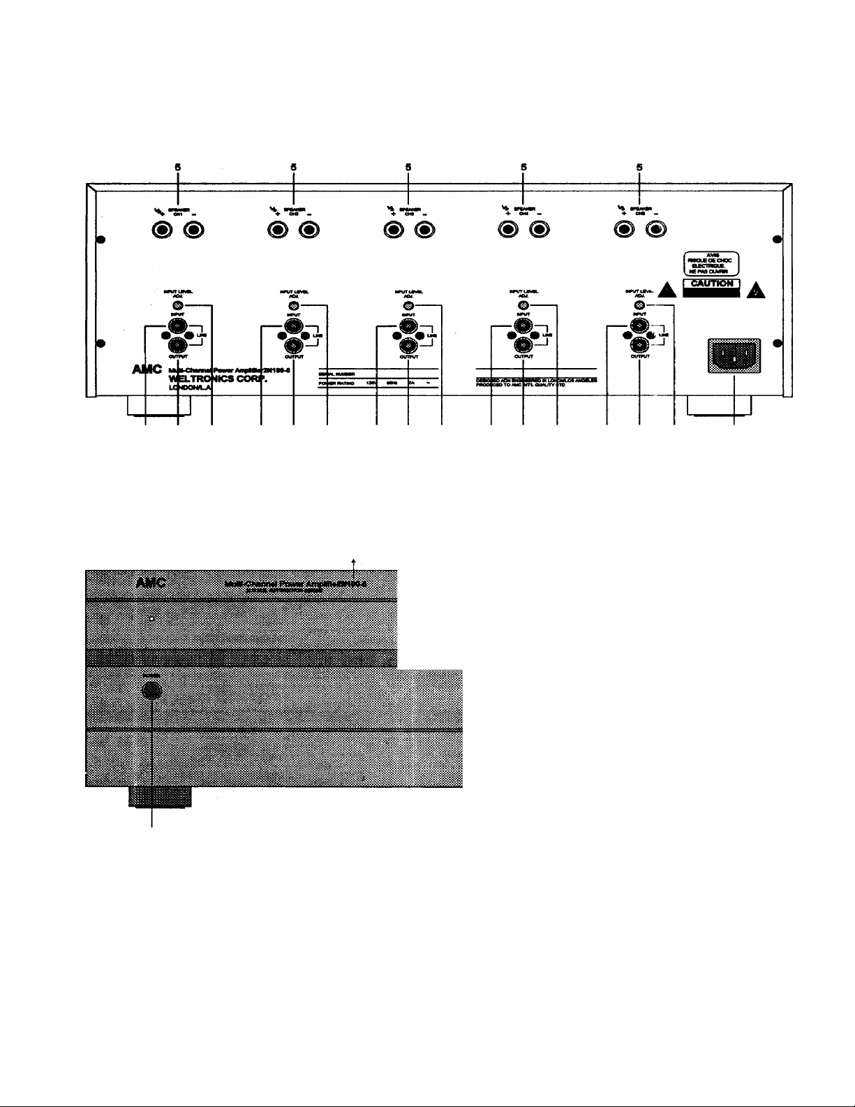
REAR PANEL CONNECTIONS/FRONT PANEL CONTROLS
REAR PANEL
432 432 432 432
1.MAINS INLET
2.INPUT LEVEL CONTROLS
3.L1NE OUTPUTS
FRONT PANEL
4 3 2
4. LINE INPUTS
5. LOUDSPEAKER TERMINALS
1. POWER SWITCH
Page 5

REAR PANEL CONNECTIONS FRONT PANEL CONTROLS
1. MAINS INLET
Connect the AC line cord in to the mains inlet
and plug the AC cord plug into a nearby wall
outlet that provides the correct AC power line
voltage.
2. INPUT LEVEL CONTROLS
Each channel of the 2N100-5/25100 has its own,
independent level control. Before turning on the
2N100-5/25100 for the first time, make sure that
all level controls are set to their fully clockwise
position. These controls can be used for various
functions. For example, they can be used to
match the levels of loudspeakers in a multi-room
installation, or to lower the sensitivity of the
power amplifier, so that the volume control on
pre-amplifier is at a more convenient and usable
position. They can also be used to optimise the
balance in a stereo system.
3. LINE OUTPUTS
Each input has an accompanying line output
which will pass the signal onto another amplifier
input or other line-level device.
4. LINE INPUTS
There are five RCA phono connectors on the
back panel that connect to the inputs of each of
the power amplifiers.
1. POWER SWITCH
The press button switch marked power can be
used to switch the 2N100-5/25100 on or off.
When the 2N100-5/25100 is switched on, the
small indicator above the power switch will glow
green.
5. LOUDSPEAKER TERMINALS
The 2N100-5/25100 is equipped with binding
post type speaker terminals that are desiged to
handle the extremely high peak currents that this
amplifier is capable of giving. Connections from
these terminals to the loudspeakers should be
made with heavy-duty wire. Standard wire of 16
gauge or thicker is recommended especially if
low impedance loudspeakers are used.
Page 6

SPECIFICATIONS
2N100-5
Rated power into 8 ohm (IMF)..................................................................................130 W
Rated T.H.D. 20Hz-20KHz......................................................................................0.03 %
Clippii g power into 8 ohm......................................................................................140 W
Dynamic power into 8 ohm....................................................................................210 W
Curretst limit into 0.1 ohm and 1 ohm
Damping factor.........................................................................................................>200
Input sensitivity for 100W output Power into 8 ohm...............................................1 Vrms
Input npedance.....................................................................................22K ohm//150pF
Frequency response 20Hz-20KHz.....................................................................+/- 0.3 dB
-3dB..................................................................<5Hz/>110KHz
Signât to noise ratio "A" WTD (ref. 1W/8 ohm)......................................................>100 dB
Separation 20KHz...........................................................................................................>70 dB
................................................................
30 Amps
OTHtiRS
Dimer sions (WxHxD).........................................................................432x152x330 mm
Net weight 2N100-5/25100......................................................................................18.6 Kg
Shipping weight (2 pieces) 2N100-5/25100............................................................. 39.1 Kg
25100
100 W
0.03 %
now
160 W
25 Amps
>180
1 Vrms
22Kohm//150pF
+/- 0.3 dB
<5Hz/>110KHz
>100 dB
>70 dB
432x152x330 mm
16.3 Kg
34.5 Kg
Page 7

SAFETY INSTRUCTION
1. READ INSTRUCTIONS
All tlw satoty and oparating instructions should be read before the
appliance is operated.
2. RETAIN INSTRUCTIONS
The safety and operating instructions should be retained for future
reference.
3. HEED WARNINGS
All warnings on the appliance and in the operating instructions
should be adhered to.
4. FOiXOW INSTRUCTIONS
AH oparating and use instructions should be followed.
5. WATER AND MOISTURE
The appliance should not be used near water- for example, near a
bathtub, washbowl, kitchen sink, laundry tub, in a wet bamment, or
near a swimming pool, etc.
6. CARTS AND STANDS
The appliance should be used only with a cart or stand that is
recommended by the manufacturer.
6A.
An appliance and cart combination
should be moved with care. Quick stops,
excessive force, and uneven surfaces
may cause the appliance and cart
combirtation to overturn.
7. WALL OR CEIUNQ MOUNTING
This equipment is not designed for use mounted on a wall or a
ceiling.
S. VENTILATION
The appliance should be situated so that its location or position does
not interfere erith its proper ventilation. R>r example, the appliance
should not be situated on a bad, sofa, rug, or similar surface that may
block the ventilation openings; or placed in a built-in installation,
such as bookcase or cabinet that may impede the flow of air through
the ventilation openings.
».HEAT
The appliance should be situated away from heat sources such as
rtuliators, heat registers, stoves, or other appliances (including
amplifiers) that produce heat.
10. POWER SOURCES
The appllanoe should be connected to a power supply only of the
type described in the operating instructions or as marked on the
appliance.
11. POWER-CORD PROTECTION
Power-supply cords should be routed so that they are not likely to be
walked on or pinched by items placed upon or against them, paying
particular attention to cords at plugs, comvenience receptacles, and
the point where they exit from the appliance.
12. CLEANING
The appliartoe should be cleaned only as rMommended by the
manufacturer.
13. NON USE PERIODS
The power cord of the appliance should be unplugged from the outlet
when left unused for a king period of time.
14. OBJECT AND LIQUID ENTRY
Care should be taken so that objects dc not fall and liquids are not
spilled into the enclosure through openings.
15.SERVICINO
The user shouid not attempt to service the appliance beyond that
described in the operating instructions. All other senricing should be
referred to qualified service peraonnel.
16. DAMAGE REQUIRING SERVICE
The appliance should be serviced by qualified service personnel
vrhen:
a) The power-supply cord or the plug has been damaged; or
b) Objects have fallen, or liquid has been spilled into the applianoe;
or
c) The applianoe has been exposed to rain; or
d) The appliance does not appear to operate normally or exhibits a
marked change in performance; or
e) The applianoe has been dropped, or the enclosure damaged.
17. POWER UNES
(APPUES TO TUNER AND RECEIVERS ONLY)
An outdoor antenna should be located away from povrer lines.
IS. OUTDOOR ANTENNA GROUNDING
(APPUES TO TUNER AND RECEIVERS ONLY)
If an outside antenna is connected to the receiver, be sure the
antenna system is grounded so as to provide some protection
against voltage surges and built uj> static charges.
Section 810 of the National Bectrical Code, ANSI/NFPA No. 70-1964,
provides information with respect to proper grounding of the mast
and supporting structure, grounding of the lead-in wire to an antenna
discharge unit, size of grounding conductors, location of
antenna-discharge unit, connection to grounding electrodes, and
requirements for the grounding electrode. See Rgure.
a) Use No. 10 AWQ (5.3 mm^) copper. No. 8 AWG (8.4mm^)
aluminum. No. 17 AWG (1.0mm^) copper-dad steel or bronze
wire, or larger, as a ground wire.
b) Secure antenna lead-in arnf grouruf wires to house with stand-off
insulators spaced from 4-6 feet (1.22-1.83 m) apart.
c) Mount antenna discharge unit as dose as possible to where lead-in
enters house.
d) Use jumper wire not smaller than No. 6 AWG (13.3 mm^) copper,
or the equivalent, when a separata antenna-grounding electrixle
is used. See NEC Section 810-21 (j).
Antenna Grounding According to
the National Electrical Code
CiGCUod« SytlBm
»»NationBi ElGciricBl Cod«
Av«»l«bl« from Ubriry. book
stor«t, or Naiion«! Fir« Proi«ction
AsBociation (S«ti«rym«rch Park.
Quincy MA 02269)
(NEC»* Art 2S0 Pin H)
Page 8

WELTRONICH CORP.
LONOON/LA.
 Loading...