

Page 1

TABLE OF CONTENTS
General information. ................................................................................................................................................................... 2
Purpose of the manual. ............................................................................................................................................................... 2
Identication of manufacturer and equipment. ............................................................................................................................ 3
Safety information. ...................................................................................................................................................................... 3
Safety regulations. ...................................................................................................................................................................... 3
Safety devices. ............................................................................................................................................................................ 4
Safety signals. ............................................................................................................................................................................. 5
Technical information. ................................................................................................................................................................ 6
Technical specications............................................................................................................................................................... 6
General description of the appliance........................................................................................................................................... 7
Main parts . ................................................................................................................................................................................. 8
Installation. ................................................................................................................................................................................... 9
Packing and unpacking. .............................................................................................................................................................. 9
Planning of system installation. ................................................................................................................................................... 9
Setting up of the perimeter wire. ................................................................................................................................................11
Re-entry method to the charging station. ...................................................................................................................................11
Setup of the robot’s quick re-entry to the charging station. ....................................................................................................... 12
Preparation and marking the boundaries of the work areas. .................................................................................................... 13
Installation of perimeter wire. .................................................................................................................................................... 17
Installation of the charging station and power supply unit......................................................................................................... 18
Adjustments. .............................................................................................................................................................................. 20
Adjustment recommendations................................................................................................................................................... 20
Adjustment of cutting height. ..................................................................................................................................................... 20
Use and operation. .................................................................................................................................................................... 21
Requirements for use. ............................................................................................................................................................... 21
Description of control panel and menu overview....................................................................................................................... 21
Initial setup. ............................................................................................................................................................................... 23
Menu access. ............................................................................................................................................................................ 23
Menu settings – programming mode......................................................................................................................................... 24
Initial start up – automatic mode. .............................................................................................................................................. 28
Robot safety stop. ..................................................................................................................................................................... 28
Use of the robot in closed areas with no charging station......................................................................................................... 29
Visualising the display during the work phase. ......................................................................................................................... 30
Prolonged inactivity and restarting. ........................................................................................................................................... 30
Battery charging after prolonged inactivity. ............................................................................................................................... 31
Operating tips. ........................................................................................................................................................................... 31
Routine maintenance. ............................................................................................................................................................... 32
Maintenance recommandations. ............................................................................................................................................... 32
Scheduled maintenance table. .................................................................................................................................................. 32
Robot cleaning. ......................................................................................................................................................................... 33
Troubleshooting. ....................................................................................................................................................................... 34
Troubleshooting guide. ............................................................................................................................................................. 34
Part replacement. ...................................................................................................................................................................... 37
Recommendations for replacing parts. ..................................................................................................................................... 37
Battery replacement. ................................................................................................................................................................. 37
Blade replacement. ................................................................................................................................................................... 37
Robot disposal. ......................................................................................................................................................................... 38
Ec declaration of conformity. ................................................................................................................................................... 39
Warranty rules. .......................................................................................................................................................................... 40
Conditions and limitations. ........................................................................................................................................................ 40
How to request warranty service. .............................................................................................................................................. 40
Additional denitions. ................................................................................................................................................................ 40
EN
Reproduction, even partial, of this document without written permission by the manufacturer is strictly forbidden. The
manufacturer assumes a policy of continual improvement and reserves the right to modify this document without prior notice
on condition that the changes do not constitute health and safety risks.
© 2008 – Text, illustrations and page layout by Tipolito La Zecca. The text may be reproduced, in whole or in part, on condition
that the author is mentioned.
MD-CT-RO-15-R1.3 - EN - 10-2020
1
User’s manual
Page 2
GENERAL INFORMATION
EN
PURPOSE OF THE MANUAL
This manual forms an integral part of the appliance and was produced by the Manufacturer to provide the necessary
•
information to people authorised to interact with it during its working life.
Operators of the appliance must adopt correct working practices and must carefully read and follow all the instructions
•
contained in this manual.
This information is original and supplied by the manufacturer.
•
Carefully read the instructions contained in this manual to avoid any unnecessary risks to people’s health and safety, as well
•
as economic damages.
Keep this manual in a safe and easily accessible place for quick reference.
•
Some information and illustrations contained in this manual may not perfectly correspond with the appliance in your
•
possession; however, this does not affect its functioning.
The Manufacturer reserves the right to make changes without any obligation to provide prior notice.
•
The following symbols are used throughout this manual to highlight some particularly important information or to identify
•
some important specications.
Danger - Attention
This symbol indicates situations involving imminent danger, which, if ignored, could put people’s health and
safety at risk.
Warning – Caution
This symbol indicates situations where it is necessary to behave in a certain way in order to avoid putting
people’s health and safety at risk, and to protect the device.
Important
This symbol identies particularly important technical information which must not be ignored.
User’s manual
2
Page 3
IDENTIFICATION OF MANUFACTURER AND EQUIPMENT
Serial Number :
Manufactured by
Xxxxxxxxxxxxxxxxxx, Xxxxxxxxxxxxxxxxx
XXXXX Xxxxxxxxxxxxxxxxxxxxxxxx (XX) - XXXX
XXXXXXXXXXXXXX
MODEL
TYPE MFG
(C) Manufacturing year
(C) Model
(B) EC conformity
label
(A) Name of manufacturer
(D) Technical
specifications
(C) Serial
number
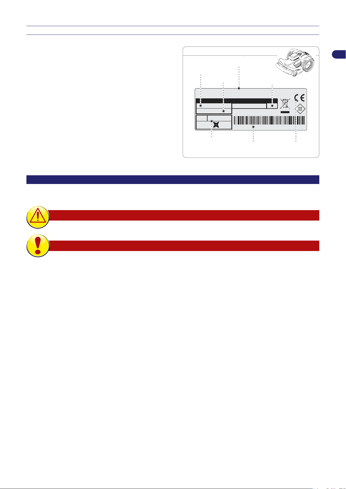
DATA PLATE
(C) Version
The nameplate shown here is applied directly onto the appliance.
It contains references and all the information essential for safely
operating the device.
For any technical requirements, please contact the Manufacturer’s
Technical Service Centre or an authorised dealer.
For technical assistance, please indicate the data reported on the
identication plate, the approximate hours of use and the type of
fault detected.
A. Name of manufacturer.
B. CE conformity label.
C. Model and Version / serial number / manufacturing year.
D. Technical data: voltage, current, protection rating, mass,
cutting width.
SAFETY INFORMATION
The manufacturer carefully considered the possible hazards and personal risks that may result from interacting with the
equipment. The purpose of this information is to inform users on the need to use extreme caution in order to avoid risks.
EN
SAFETY REGULATIONS
THIS PRODUCT COMES WITH A BLADE AND IS NOT A TOY!
Please read the manual carefully, especially the safety instructions, and make sure you
•
understand them fully before using the product. Only use the equipment for the purposes
specically intended by the manufacturer. Carefully follow the instructions on operation,
maintenance and repair.
When using the robot, make sure there is no one in the working area, in particular children, the
•
elderly or disabled and pets. Otherwise, program the robot to operate during hours when there
is no one in this area. Keep an eye on the robot if you know that pets, children or other people
are in the area. If a person or animal is found on the robot’s path, stop it immediately.
In working areas not bounded by a fence that can not be easily climbed over, supervise the
•
device during the operation.
Warning signs shall be placed around the working area of the robotic lawnmower if it is used
•
in public areas. The signs shall have the following text: "Warning! Automatic lawnmower!
Keep away from the machine! Supervise children!"
This robot is not suitable for use by children and people with reduced physical, sensory or
•
mental capabilities or inexperienced people who are not familiar with the product, unless they
are supervised by a person responsible for their safety or have received instructions on how
to use the appliance. Children should be supervised to ensure that they do not play with the
appliance.
Do not allow the robot to be used by people who do not know how it works.
•
Operators who perform maintenance and repair work must be fully conversant with its special
•
features and safety regulations. Before using the robot, carefully read the operating manual and
make sure you understand the instructions.
Never remove, bypass or tamper with the safety devices installed. The Manufacturer shall not
•
be held liable if non-original spare parts are used. Failure to comply with this requirement may
seriously endanger the health and safety of people.
3
User’s manual
Page 4

EN
Check that there are no toys, tools, branches, clothing or other objects on the lawn which
•
can damage the blades. Any objects on the lawn can also damage or prevent the correct
functioning of the robot.
Never allow people to sit on the robot. Never lift the robot to inspect the blade or to carry it while
•
it is running. Do not place hands and feet under the robot when it is in operation.
Do not use the robot when a sprinkler system is running. In this case, program the robot and
•
the sprinkler system so that they do not operate at the same time. Do not wash the robot with
high-pressure water jets and do not immerse it in water, partially or completely, as it is not
watertight.
Disconnect the power supply and activate the safety device before performing any adjustment
•
or maintenance that the user is authorised to perform. Use the personal protection devices
recommended by the Manufacturer, in particular, always wear protective gloves when handling
the cutting blade.
Cleaning and maintenance must not be performed by unsupervised children.
•
Do not use the robot when the cutting blade is damaged. Replace the cutting blade.
•
Do not use the robot with damaged external parts. If the mechanical parts of the robot are
•
damaged, replace them.
Do not use the robot if the power cord of the transformer is damaged. A damaged cord can lead
•
to contact with live parts. To avoid any risk, have the cord replaced by the manufacturer or by
its technical service centre or by a person with similar qualications.
If the power cord is damaged during use, press “STOP” to stop the robot and disconnect the
•
power cord from the electrical socket.
Visually check the robot regularly to make sure the blade, mounting screws and cutting
•
mechanism are not worn or damaged. Make sure that all the nuts, bolts and screws are
tightened to ensure that the robot is in good working condition.
If the robot starts to vibrate abnormally during use, press “STOP” and disconnect the power
•
cord from the electrical socket.
Never use and recharge the robot in explosive and/or ammable environments.
•
Only use the battery charger and power supply unit supplied by the manufacturer. Improper
•
use may cause electric shocks, overheating or leakage of corrosive liquids from the battery.
If any liquid leaks, wash the battery with water/neutraliser; in case of contact with eyes, seek
medical attention.
SAFETY DEVICES
1. Obstacle detector
The bumper sensor is activated if the robot strikes a solid object greater than 10 cm (3.94 ") in height, which stops the movement
in that direction and moves backwards to avoid the obstacle.
2. Inclinometer
If the robot works on a slope which is steeper than the maximum limit, or tips over, the robot will stop the cutting blade.
3. Emergency stop switch
Located on the upper part of the robot with the word "STOP" larger than the other commands on the keypad. Pressing this button
at any time during operation will immediately stop the movement of the lawn mower robot and the rotation of the blade will stop.
4. Over-current protection
Each motor (blade and wheels) is monitored continuously during operation for any situation that may cause them to overheat. If
this occurs in the wheel motor, the robot will attempt to move in the opposite direction. If the over-current persists, the robot will
stop and signal an error. If the cutting blade motor overheats, there are two intervention ranges. If the parameters fall within the
rst range, the robot will perform the manoeuvres to unblock the cutting blade. If the over-current is below the protection range,
the robot will stop and signal a motor error.
5. No signal sensor
If there is no signal, the robot will automatically stop.
User’s manual
4
Page 5
STOP
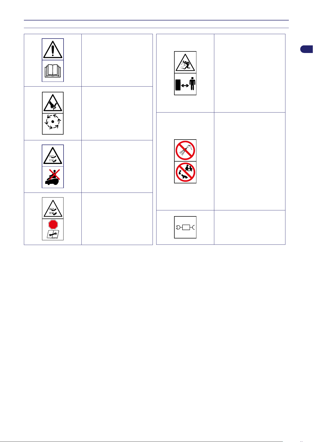
SAFETY SIGNALS
Read user instructions carefully
to understand meanings before
using the machine.
Do not touch the rotary blade
and do not place your hands or
feet underneath the machine
when it is running. Wait until
the blade and rotating parts
come to a complete stop before
accessing.
Do not ride on the machine.
Keep an adequate safe distance
from the machine while it is
running.
While the robot is working,
make sure there are no people
in the working area (especially
children, elderly or disabled
people) and pets. Keep children,
pets and other people at a safe
distance when the machine
is functioning. To prevent that
risk, we advise scheduling the
robot's mowing activities at
suitable times.
Warning! Do not spray water on
the machine to clean or wash it.
While the robot is working,
make sure there are no people
in the working area (especially
children, elderly or disabled
people) and pets. Keep children,
pets and other people at a safe
distance when the machine
is functioning. To prevent that
risk, we advise scheduling the
robot's mowing activities at
suitable times.
EN
STOP
Operate the safety device
before working on or lifting the
machine.
Use the robot only with the
power supplies indicated in
the “Technical Data” of the
“Technical Information” chapter.
5
User’s manual
Page 6

EN
TECHNICAL INFORMATION
TECHNICAL SPECIFICATIONS
Model
Description
8040EL0 8040EL0 8040EL0 A041EL0
Power KIT
Maximum recommended surface that can be mowed
2
Working capacity ( -20%(*)) m
Features
Dimensions (W x H x D) mm 635x464x330 784x536x330
Robot weight (incl. battery) kg 15,5 15,8 15,8 17,8
Cutting height (Min-Max) mm (") 20 - 65 (0,78-2,56 ")
Diameter of blade mm (") 250 (9,84 ") 360 (14,17 ")
Motors without brushes
Cutting blade speed RPM 3000 2500
Ground speed Metres / Minute 30 ( 97,7 ') 35 (114 ')
Maximum recommended slope
managed (*)
(ft2)
%
5.8Ah - 5A
MEDIUM
1800
(19368)
45% allowable, based on the lawn conditions and accessories
installed.
35% maximum managed and recommended in conditions of a
trimmed lawn.
20% in proximity of the outside edge or perimeter wire.
8.7Ah - 8A
PREMIUM
3200
(34432)
8.7Ah - 8A
EXTRA
PREMIUM
3200
(34432)
10.35Ah - 10A
ULTRA
6000
(64583)
ROBOT: -10°(14 F.) (Min) +50° (122 F.) (Max)
Ambient operating temperature Max °C
Measured sound power level dB(A) 63 65
Water protection class IP
Electrical features
Power supply unit (for lithium battery)
Type of accumulator and charging batteries
Rechargeable Lithium-Ion Battery
(rated voltage)
Type of charging contact contact inductive contact
Average recharging time hh:mm 1:30
Average mowing duration after a full
charge cycle (*)
hh:mm 02:45 03:45 03:45 04:00
CHARGING STATION: -10°(14 F.) (Min) +45° (113 F.) (Max)
BATTERY CHARGER: -10°(14 F.) (Min) +40° (104 F.) (Max)
ROBOT: IPx5
CHARGING STATION: IPx4
BATTERY CHARGER: IPx4
Mean Well
ELG-150-30ZCTE
Input:
100 - 240 V~; 2 A;
50/60 Hz; Class 1
Output:
29.4 V
25.9V 5.8Ah 25.9V 8.7Ah 25.9V 8.7Ah
; 5.0 A
Mean Well
ELG-240-30ZCTE
Input:
100 - 240 V~; 2.2 A;
50/60 Hz; Class 1
Output:
29.4 V ; 8.0 A
ELG-300-30ZCTE
100 - 350 V~; 3.0 A;
50/60 Hz; Class 1
29.4 V ; 10 A
Mean Well
Input:
Output:
25.2V
10.35Ah
(*) Depends on the condition of the grass, lawn and the complexity of the mowing area.
User’s manual
6
Page 7
Frequencies
RANDOM OPERATION
Transmitter for the robot driving
Bluetooth
GSM
Equipment / Accessories / Functions
Areas managed, including the
primary zone
Rain sensor Standard
Eco Mode -Self-programming
(patented)
Connect module (GPS, GPRS) Standard
Re-entry method to the charging
station
Maximum length of perimeter wire
(approximate, calculated based on a
regular perimeter)
(*) Depends on the condition of the grass, lawn and the complexity of the mowing area.
m (') 1000 (3280 ')
Frequency band of work (Hz) 500 - 60000
maximum radio frequency power (dBm) < 10
Frequency band of work (MHz) 2402 - 2480
maximum radio frequency power (dBm) < 14
Frequency band of work (MHz) 850/900/1800/1900
maximum radio frequency power (dBm) < 33
8
Standard
"V-Meter" - "follow wire"
GENERAL DESCRIPTION OF THE APPLIANCE
EN
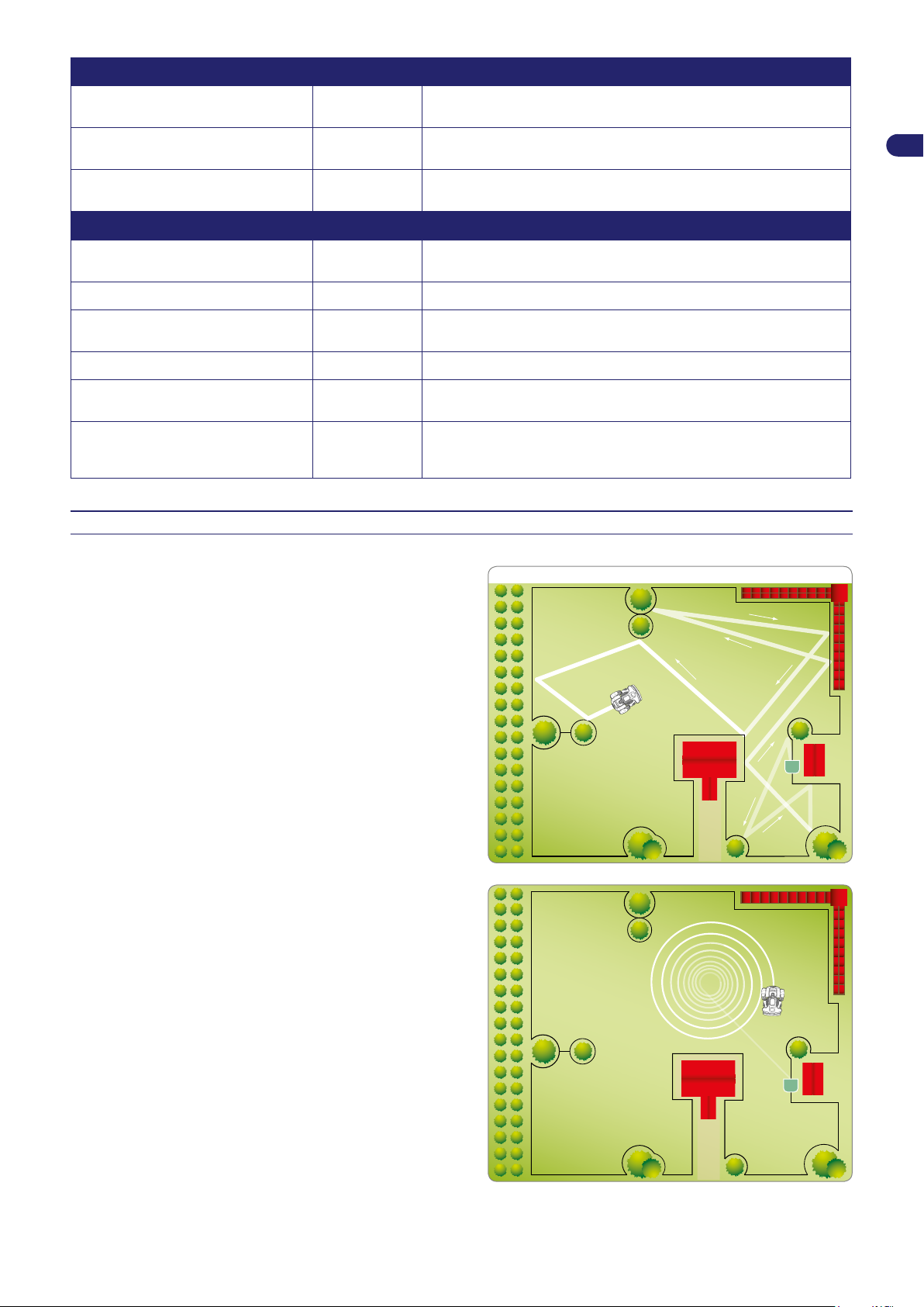
The appliance is a robot designed and built to automatically trim
grass in gardens and house lawns at any time of the day or night.
It is small, compact, silent and easy to transport.
Depending on the characteristics of the surface to be trimmed,
the robot can be programmed to work on more than one area: a
primary area and secondary areas (according to the specications
of the various models).
During operation, the robot trims the area marked off by the
perimeter wire.
When the robot detects the perimeter wire or encounters an
obstacle, it changes direction in a random manner and starts
mowing again in a new direction. The robot does not cross the
perimeter wire for a distance greater than half its length.
According to its operating principle random, the robot automatically
trims the entire delimited area of the lawn (see gure).
The robot is able to recognise the presence of higher and/or thicker
grass in an area of the garden and to automatically activate, if
considered necessary, the spiral movement for a perfect nish.
The spiral movement can also be activated by pressing “ENTER”
while the robot is mowing.
The lawn surface that the robot is able to trim depends on a series
of factors, such as:
model of the robot and type of batteries installed;
•
characteristics of the area (irregular perimeters, uneven
•
surfaces, divided areas, etc.);
characteristics of the lawn (type and height of the grass,
•
moisture, etc.);
conditions of the blade (level of sharpness, without residuals
•
and deposits, etc.);
7
User’s manual
Page 8
EN
4
14
9
7
6
8
13
10
1
2
3
11
5
12
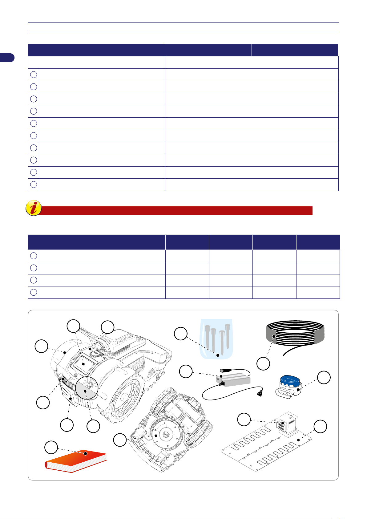
MAIN PARTS
MODEL 8040EL0 A041EL0
Version A
1
Robot �
2
Keyboard commands �
3
Rain sensor �
4
Handle �
5
Cutting blade �
6
Perimeter wire coil 0
7
Pegs 20
8
Charging station �
9
User manual �
10
Joint for perimeter wire -
Important
In some commercial setups, the power kit may be sold separately.
POWER KIT MEDIUM PREMIUM
11
Battery 25.9V 5.8Ah 25.9V 8.7Ah 25.9V 8.7Ah 25.2V 10.35Ah
12
Power Supply unit 5.0 A 8.0 A 8.0 A 10A
13
Transmitter and Charging Tower contact contact inductive contact
14
Charging Module contact contact inductive contact
EXTRA
PREMIUM
ULTRA
User’s manual
8
Page 9
INSTALLATION
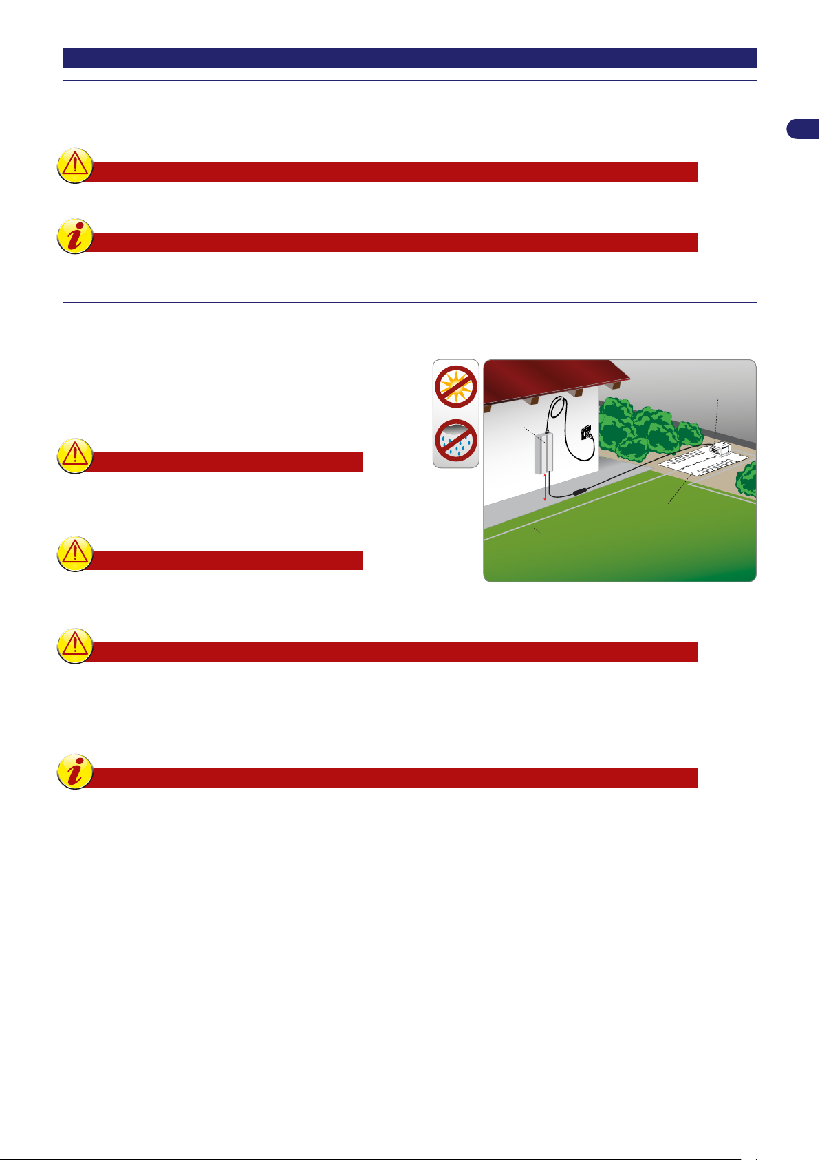
Power supply
unit
perimeter wire
charging station
Min. height.
160 cm / 63"
transmitter
PACKING AND UNPACKING
The equipment is delivered suitably packaged. When unpacking, carefully remove and check the integrity of the parts.
Warning – Caution
Keep plastic wrapping and plastic containers away from infants and children: risk of suffocation!
Important
Keep the packaging materials for future use.
PLANNING OF SYSTEM INSTALLATION
The robot is not difcult to install, but requires some preliminary planning in order to nd the best area for installing the charging
station, power supply unit and for laying out the perimeter wire.
The charging station must be positioned on the edge of the
•
lawn, preferably in the largest area from which other areas of
the lawn are easily accessible. The area where the charging
station is installed is hereinafter referred to as the “Primary
Area.”
Warning – Caution
Position the power supply unit in an area that
cannot be reached by children. For example, at a
height above 160 cm (63 ").
EN
Warning – Caution
Make sure only authorised people have access to
the power supply.
Warning – Caution
When connecting the electricity, it is necessary that a power outlet is positioned near the installation area.
Make sure the connection to the mains power complies with the applicable laws. To operate in complete
safety, make sure the electrical system, which is connected to the power supply unit, is equipped with a wellfunctioning earthing system. The supply circuit shall be protected by a residual current device (RCD) with a
tripping current of not more than 30 mA.
Important
It is advisable to install the unit in a cabinet for electric components (for outdoor or indoor use), equipped
with a key lock, and well-ventilated to maintain a correct air circulation.
The robot must be able to easily nd the charging station at the end of the work cycle, which will also be the starting point for
•
a new work cycle and for reaching any other work areas, hereinafter referred to as “Secondary Areas.”.
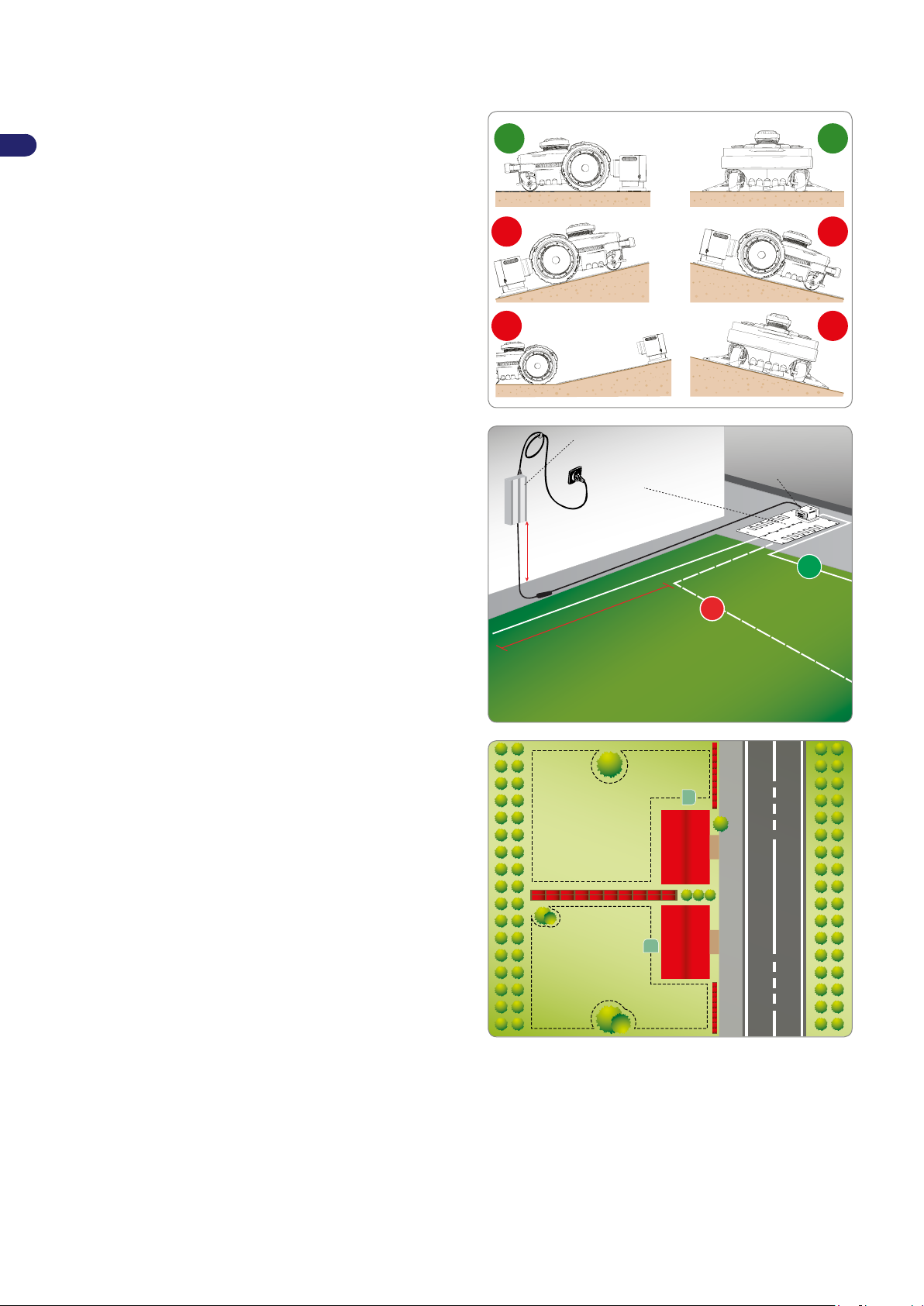
Position the charging station according to these rules:
•
on level ground;
-
on compact and stable ground with good drainage;
-
preferably in the widest part of the lawn;
-
in case of sprinklers, make sure the water jets are not directed inside the charging station;
-
make sure the entrance of the charging station is positioned as shown in the gure, so that the robot can enter it by
-
following the perimeter wire in a clockwise direction;
there must be a straight area of 200 cm (78,74 ") in front of the charging station;
-
any metal bars or rails separating the lawn near the station may interfere with the signal. Position the station on a different
-
side of the garden or at a safe distance from the metal barrier. For more information, please contact the Manufacturer’s
Technical Service Centre or an authorised dealer.
The charging station must be well fastened to the ground. To prevent a small step from forming at the front of the charging
•
station, position a small piece of fake grass at its entrance to stop this from occurring. Alternatively, remove part of the grassy
surface and install the charging station ush with the grass.
9
User’s manual
Page 10
EN
NO NO
OK OK
NO NO
OK
power supply unit
charging station
min height 160 cm
/ 63 "
min. distance
200 cm
/ 78,74 "
perimeter wir
e
perimeter wire
transmitter
NO
The charging station is connected to the power supply unit via a cord that must move away from the charging station on the
•
outside of the cutting area.
Position the power supply unit according to these rules:
•
in a well-ventilated area protected against atmospheric
-
agents and direct sunlight;
preferably inside your home, a garage or shed;
-
if positioned outdoors, the robot must not be exposed to
-
direct sunlight and water. Therefore, it must be protected
inside a ventilated box. Do not position in direct contact with
the soil or humid environments;
position it on the outside of the lawn and not inside;
-
stretch out the excess cord going from the charging station
-
to the power supply unit. Do not shorten or lengthen the
cord.
The incoming section of the wire must be straight and aligned
•
perpendicularly to the charging station by at least 200 cm
(78.74 in.) and the outgoing section must move away from the
charging station; this allows the correct re-entry of the robot.
If the robot is installed near an area which has another robot
(from the same or another manufacturer), then the transmitter and
receiver of the robot must be modied during installation so that
the frequencies of the two robots do not interfere with other. In this
situation, contact the closest customer service centre.
User’s manual
10
Page 11
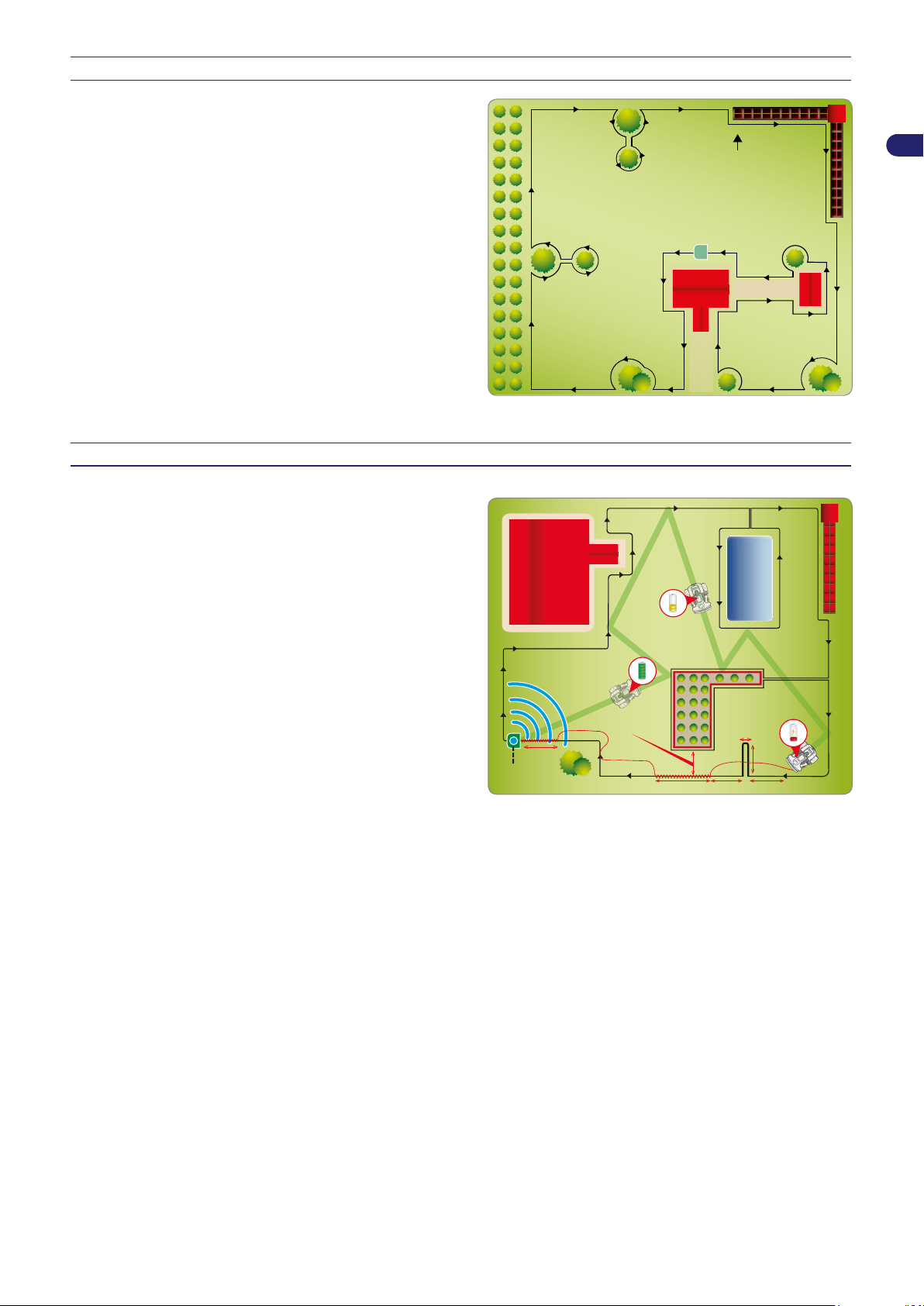
SETTING UP OF THE PERIMETER WIRE
track for laying the perimeter wire
step
lower 2 mt.
5 cm.
2 mt.
2 mt.
2 mt.
10 mt. 1,5 mt.
charging
station
Before installing the perimeter wire, it is necessary to check the
entire surface of the lawn. Make any necessary adjustments to the
grassy surface during the laying of the perimeter wire in order to
allow the robot to function correctly.
1. Evaluate the best method for returning to the charging station
according to the instructions described in the chapter “REENTRY METHOD TO THE CHARGING STATION”.
2. Evaluate whether a special installation of the perimeter wire
is necessary according to the instructions described in the
chapter “SET-UP OF THE ROBOT’S QUICK RE-ENTRY TO
THE CHARGING STATION”.
3. Preparation and dening of the work areas.
4. Installation of the perimeter wire.
5. Installation of the charging station and power supply unit. When
laying the perimeter wire, respect the installation direction
(clockwise) and the rotation direction around the owerbeds
(counter-clockwise), As shown in the gure.
RE-ENTRY METHOD TO THE CHARGING STATION
The robot can return to the charging station in two different ways
based on what is set in the user menu under the eld “Settings –
Re-entry to Base.” Use the “On the Wire” method only when there
are numerous obstacles inside the garden and near the perimeter
wire (within 2 meters). In all other cases it is better to use the
“V-Meter” method for the quickest re-entry to the charging station.
EN
“Follow wire”. This method of re-entry to the charging station
commands the robot to follow the perimeter wire, positioning its
wheels on either side of the wire. If this method is activated, there
is no need to prepare the “Recall on Wire” as described below.
“V-Meter”. By setting this method of re-entry to the charging
station, the robot runs along the perimeter wire at an indicative
distance ranging from a few centimetres to one meter (3.2 '),
touching it every now and again in the curved sections until the
signal emitted by the charging station has been recognised for
guiding itself on the wire and entering correctly into the charging
station.
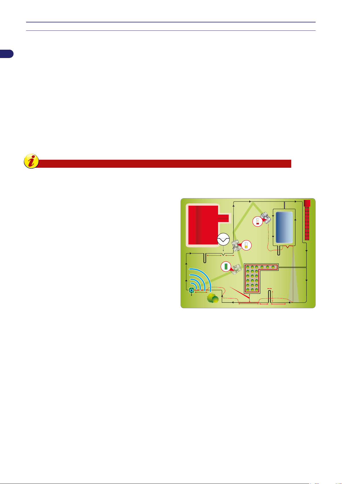
If narrow passages are present or the arrow for quick re-entry to the charging station, the wire must be positioned in a special
way, called “Recall on the wire.”
As soon as a “Recall” is recognised, the robot will follow the perimeter wire at low speed, and with more precision for around
10 meters (33 '). It will then return to the “V-Meter” re-entry mode if the quick re-entry or charging station was not encountered.
Follow these instructions to install the “Recall”:
the “Recall” is a piece of wire that extends for around 2 m (6.6 ') with a distance of 5 cm (1.96 ") between each wire;
•
the “Recall” must be positioned at a distance of 2 m. (6.6 ') in front of any narrow passages;
•
the “Recall” must be positioned in the section in front of the “Quick Re-entry”.
•
NB: If the robot does not nd the charging station within a certain amount of time, it will follow the perimeter wire in
“Follow wire” mode.
11
User’s manual
Page 12
EN
40 40
50
1,5 mt.
step
lower
2 mt.
4-10 mt.
min. 150 cm.
10 mt.
5 cm.
2 mt.
2 mt.
2 mt.
charging
station
SETUP OF THE ROBOT’S QUICK RE-ENTRY TO THE CHARGING STATION
Quick re-entry requires a special installation of the perimeter wire that allows the robot to reduce the re-entry path to the charging
station. This special installation of the perimeter wire should only be used for gardens where quick re-entry signicantly reduces
the path and where the perimeter length is greater than 200 meters.
To setup the quick re-entry, position the perimeter wire on the ground so that it forms a triangle with one side of 50 cm (19.7 ")
and the other two sides of 40 cm (15.75 ") each, as shown in the gure.
As the robot heads back to the charging station with the two wheels on either side of the wire, it intercepts this triangle and stops
moving. It then turns approximately 90° towards the inside of the garden and starts moving in the new direction until running into
the perimeter wire on the opposite side.
Arrange the wire for quick re-entry in a point where there is at least 200 cm (78.74 ") of straight wire in front of the station, and at
least 150 cm (59.05 ") of straight wire behind it.
Do not set up the wire along the straight section immediately in front of the charging station or near any obstacles. Make sure
there are no obstacles along the re-entry path that may obstruct the quick re-entry.
Do not set up the wire along excessive slope, so that the robot can recognizes easy it.The maximum slope depends on the lawn
conditions. it should be remain under approximately 20%.
Important
An incorrect setup of the robot’s quick re-entry may prevent the robot from returning to the charging station
quickly. When the robot travels along the perimeter to reach a secondary area, it may not detect the quick
re-entry setup.
The illustration provides some useful tips on how to correctly setup
the robot for a quick re-entry.
User’s manual
12
Page 13
PREPARATION AND MARKING THE BOUNDARIES OF THE WORK AREAS
NO
35 cm
(13,78 ")
100 cm (39,3 ")
45 cm
(17,71 ")
45 %
35 cm
(13,78 ")
21-45%
0-20%
0-20%
0-45%
0-20%
21-45%
perimeter wire
perimeter wire
OK
NO
NO
OK
OK
OK
Preparation of the lawn to be mowed
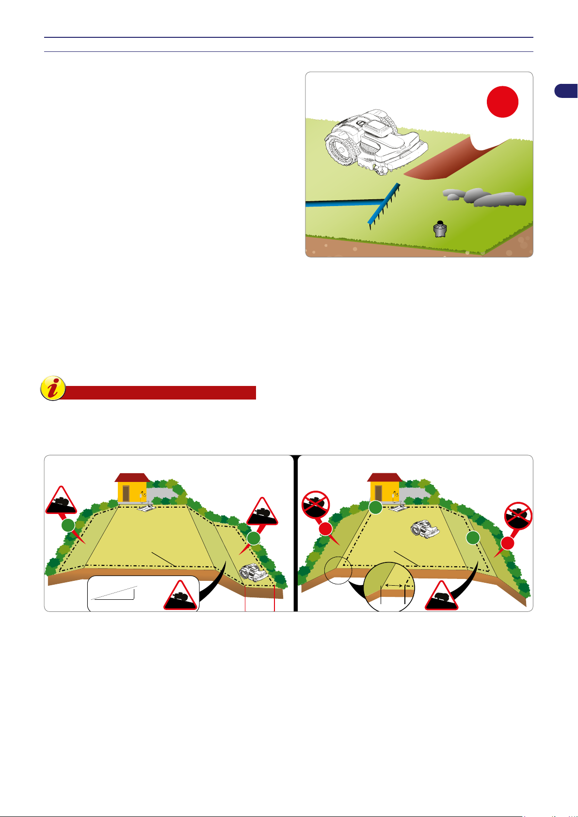
1. Make sure the lawn to be mowed is even and does not contain
holes, stones or other obstacles. If necessary, prepare the
lawn by lling in any holes and removing any obstacles. If
some obstacles cannot be removed, it is necessary to properly
mark these areas with the perimeter wire.
2. The robot can mow surfaces inside the working area with
a maximum slope of 45% (45 cm per meter in length) on a
regular dry lawn, with no risk of wheels slipping, based on
the accessories installed. In the other cases it is necessary to
respect the 35% of the slope.
The perimeter wire must be laid on the ground sloping no more
than 20% (20 cm per meter in length), being in mind that the
robot requires greater grip during the return to the charging
station. Therefore, it necessary to check carefully the lawn
conditions and to respect the limits. If the perimeter wire is
laid on the sloping more than 20%, the robot may depart from
it, to move more easily, not being able to overcome narrow
passages and to recognize the quick re-entry set up.
The slope must not increase at least 35cm inside or outside
the perimeter wire.
If these instructions should not be complied with, while the
robot is working on sloping areas and detects the wire, its
wheels could slip and make it leave the working area.
EN
If there are any obstacles on slopes that are closed to the
abovementioned limits, the ground must be uniformed for at
least 35cm in the part uphill of the obstacle to reduce the slope.
Important
Areas with slopes greater than those allowed cannot
be mowed with the robot. Therefore, position the
perimeter wire in front of the slope so that it is
excluded from the area to mow.
13
User’s manual
Page 14
EN
Track for laying
the perimeter wire
min. 70 cm / 27,56 "min. 70 cm / 27,56 "
min. 70 cm / 27,56 "
corridor with a minimum passage
of 70 cm / 27,56 " from edge to edge.
PRIMARY AREA
SECONDARY AREA
corridor with a passage
< 70 cm / 27,56 "
PRIMARY AREA
CLOSED
AREA
Marking the boundary of the work area
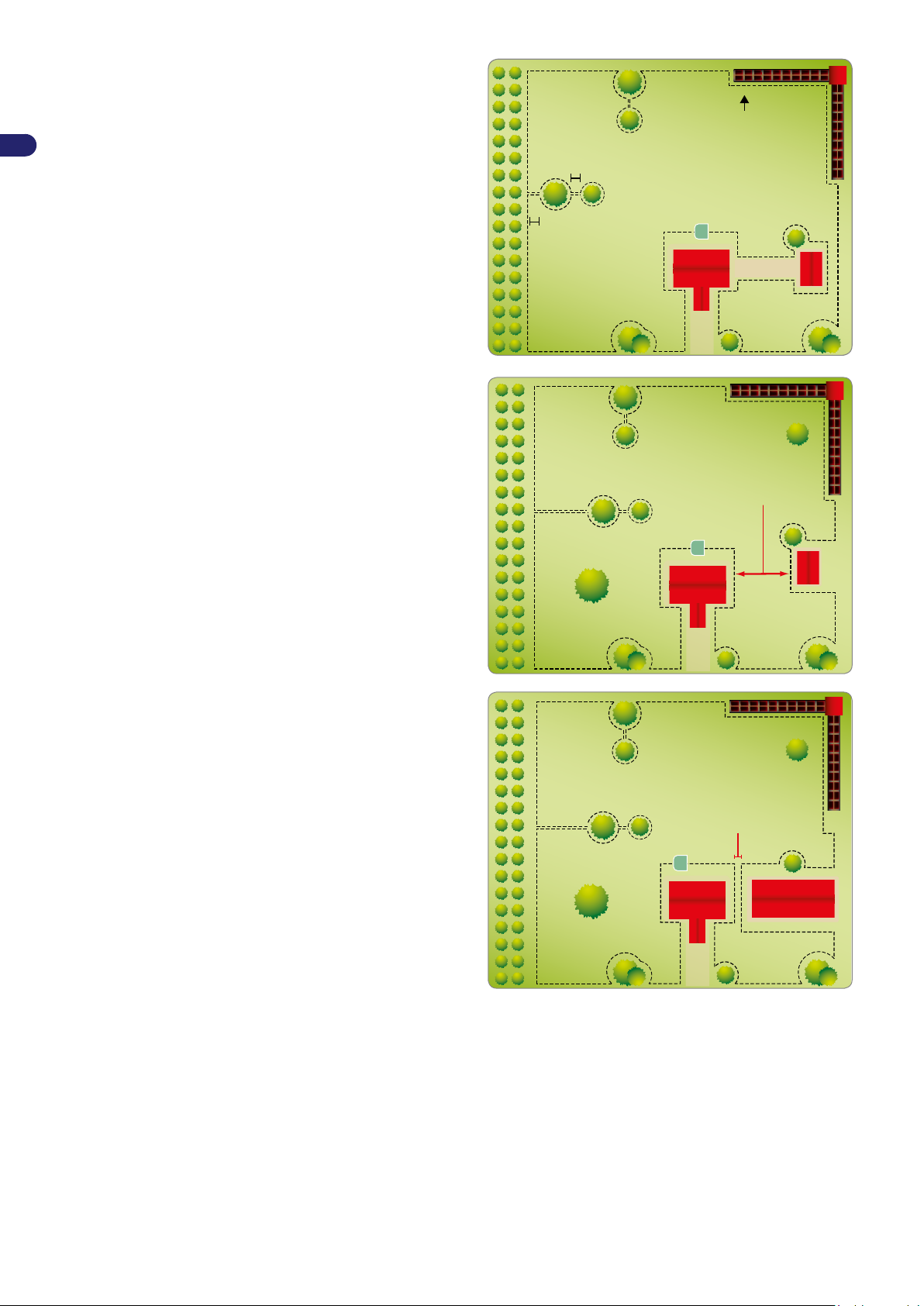
3. Check the entire lawn surface and assess whether it is
necessary to divide it into separate work areas as per the
rules described here below. Before installing the perimeter
wire, check the entire path to make this procedure easier. The
illustration shows a lawn with the track for installation of the
perimeter wire.
During installation, identify any secondary areas and closed
areas. A secondary area is part of a lawn connected to the
primary lawn with a passage that is difcult to reach by the
robot's normal movement. The area must be reachable without
any rises or drops greater than those allowed. Whether a zone
is to be dened a “secondary area” also depends on the size
of the primary area. The larger the primary area, the harder it
will be to reach narrow passages. More generally, a passage
narrower than 200 cm (78.74 ") is considered a secondary area.
The number of secondary areas managed depends on the
characteristics of the model (See “Technical Specications”).
The minimum passage allowed is 70 cm (27.56 ") from each
edge of the perimeter wire. The perimeter wire must be
positioned at a distance of (to be indicated below) from any
objects outside the lawn; therefore, the necessary space for
passing must be 140 cm (55.12 ") if there is a wall or hedge
on both sides.
If this passage is very long, the width should be more than
cm
(27.56 ") between perimeter wires.
70
During programming, it is necessary to congure the size of
the areas and the quickest direction to reach them (clockwise
or counter-clockwise), as well as the number of meters of wire
needed to reach the secondary area.
If the aforesaid minimum requirements are not met i.e. an area
separated by a rise or drop with characteristics that cannot be
managed by the robot or a passage (corridor) narrower than
70 cm (27.56 ") from perimeter edge to perimeter edge, then
this area of the lawn is considered a “Closed Area.” To mark a
“Closed Area” lay the outgoing and incoming perimeter wire in
the same track at a maximum distance of 1 cm (0.40 "). In this
case, the robot is unable to reach the area autonomously, and
must be managed as described in the chapter “Management
of Closed Areas.” The management of “Closed Areas” reduces
the square meters that can be managed autonomously by the
robot.
User’s manual
14
Page 15
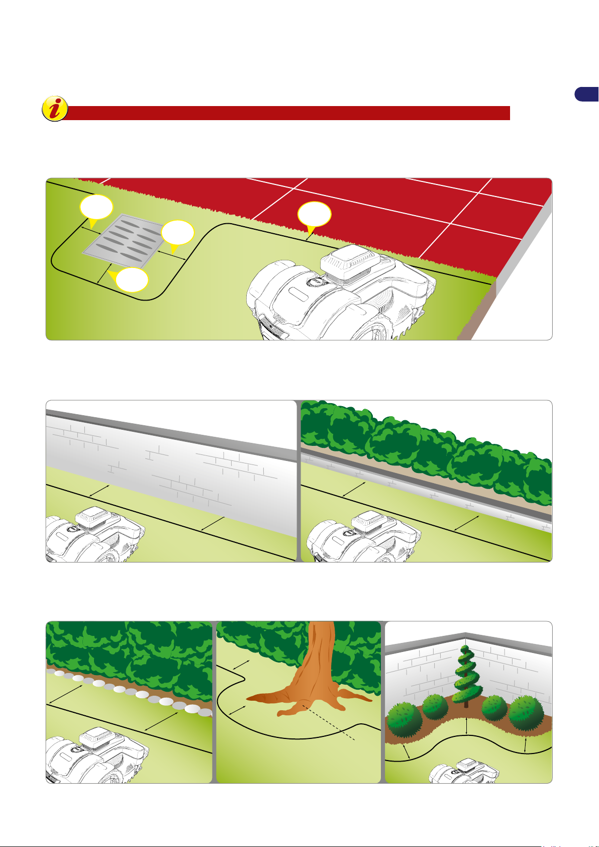
4. If there is a pavement or driveway inside or outside the work area, which is at the same level of the lawn, lay the perimeter
30 cm
1
1,81 "
30 cm
1
1,81 "
5 cm
1,97 "
30 cm
1
1,81 "
35 cm.
/ 13,78 "
35 cm.
/ 13,78 "
35 cm.
/ 13,78 "
35 cm.
/ 13,78 "
30 cm.
/ 11,81”
30 cm.
/ 11,81”
30 cm.
/ 11,81”
30 cm.
/ 11,81”
30 cm.
/ 11,81”
protruding roots
30 cm.
/ 11,81 “
30 cm.
/ 11,81 “
wire at a distance of 5 cm (1.96 ") from the edge of the pavement. The robot will come out slightly from the lawn and all
the grass will be mowed. If the pavement is made of metal or if there is a metal manhole cover, shower plate or electrical
wires, lay the perimeter wire at least 30 cm (11.81 ") from the metal object in order to prevent malfunction of the robot and
disturbances on the perimeter wire.
Important
The illustration shows an example of the elements inside and on the perimeter of the work area and the
distances to follow for the correct laying of the perimeter wire. Mark the boundary of elements in iron or other
metals (drain covers, electric connections, etc.) to prevent any interferences to the signal of the perimeter
wire.
EN
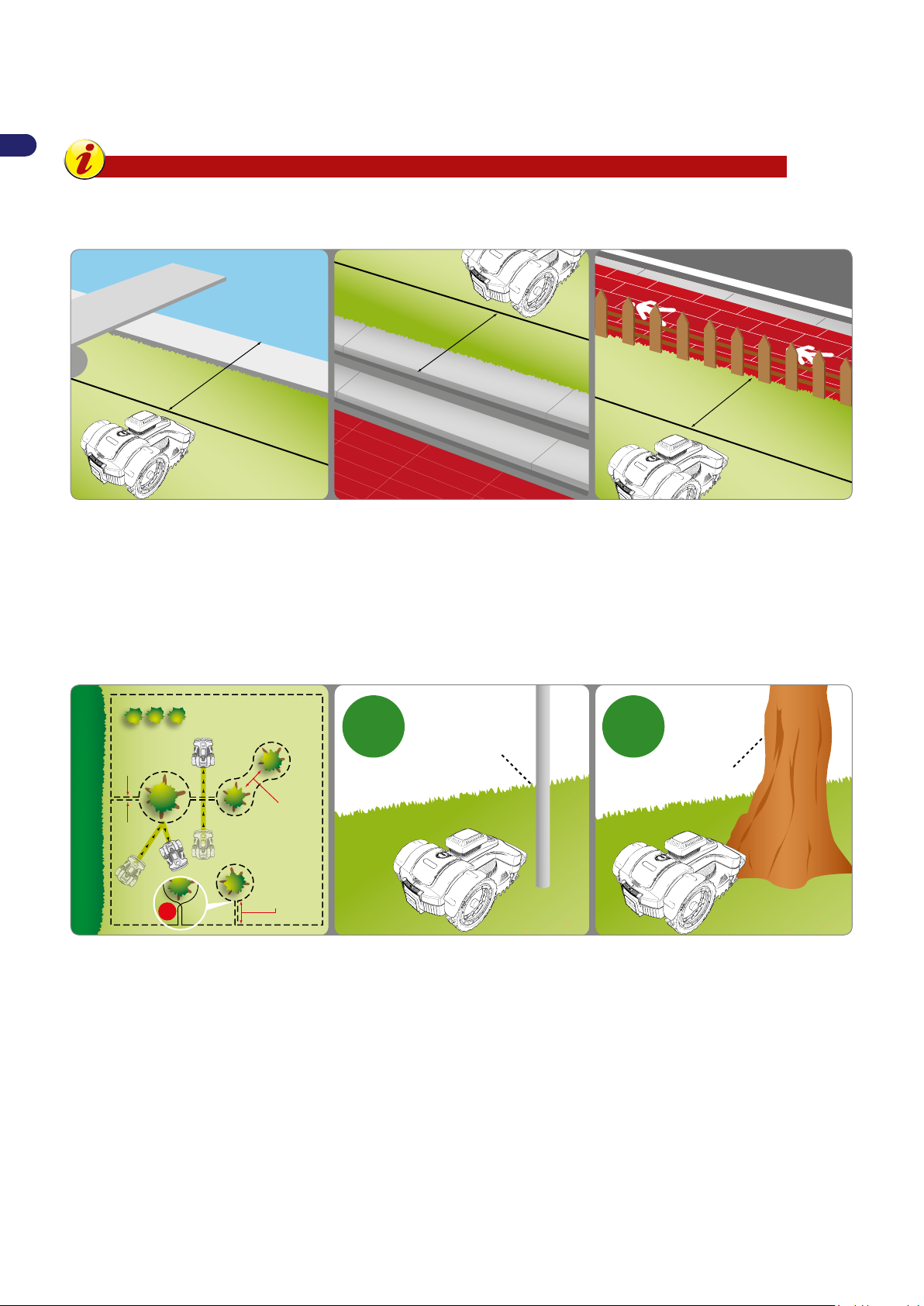
If an obstacle is present inside or outside the work area, such as a kerb or wall, lay the perimeter wire at least 35 cm (13.78") from
the obstacle. Increase the distance between the perimeter wire and the obstacle; if you don’t want the robot to hit the obstacle,
place the perimeter wire at least 40 cm (15.75") away from it. Any grass close to the edge and outside the dened work area can
be cut with a grass trimmer or brushcutter.
If a ower bed, hedge, plant with protruding roots, small ditch of 2-3 cm or small kerb of 2-3 cm is present inside or outside the
work area, lay the perimeter wire at least 30 cm (11.81 ") from the obstacle to prevent damage being done to the robot or the
obstacle.
Any grass present inside the work area can be cut and nished with a grass trimmer or brushcutter.
15
User’s manual
Page 16
EN
90 cm.
/ 35,44 “
90 cm.
/ 35,44 “
90 cm.
/ 35,44 “
NO
min. 70 cm
/ 27,56 ”
min. 70 cm
/ 27,56 ”
< 70 cm
/ 27,56 ”
< 70 cm
/ 27,56 ”
0 cm / 0 ”0 cm / 0 ”
plant
pole
OKOK
If there is a pool, pond, ravine, ditch, steps or public roads not protected by an easily crossable fence or wall inside or outside the
work area, install the perimeter wire at least 90 cm (35.43 inches) from the edge. In order to install the perimeter wire as close
as possible to the edge of the cutting area, we recommend installing a fence that is difcult to cross if adjacent to public areas,
or a fence at least 15 cm high in other cases. This will allow laying the perimeter wire at the distances described in the previous
paragraphs.
Important
Carefully follow the distances and slopes specied in the booklet to guarantee excellent installation and
proper functioning of the robot. Increase the distance by at least 30 cm (11.81 ") in the presence of slopes or
slippery ground.
Obstacles resistant to knocks, such as trees, bushes or poles without sharp edges present inside the work area do not need to
be delimited. The robot hits the obstacle and changes direction. If you don’t want the robot to knock into the obstacles and for its
safe and silent operation, all the xed obstacles need to be delimited. Slightly sloping obstacles such as ower pots, stones or
trees with protruding roots must be delimited to protect the cutting blade and the obstacles themselves.
To mark the boundary of the obstacle, start from the outside point of the perimeter nearest the object to delimit, arrange the
perimeter wire so that it reaches the obstacle, goes around it and then travels back along the previous path, observing the regular
distances described in the previous paragraphs. Overlap the outgoing wire and the incoming wire so that they pass under the
same peg, this will allow the robot to go past the perimeter wire.
For the robot to function correctly, the minimum overlapping length should not be greater than 70 cm (27.56 ") in order to allow
the robot to move regularly.
User’s manual
16
Page 17
INSTALLATION OF PERIMETER WIRE
Max.
5 cm (1,96 ")
perimeter wire
wire fastening pegs
perimeter wire
radius of 20 cm
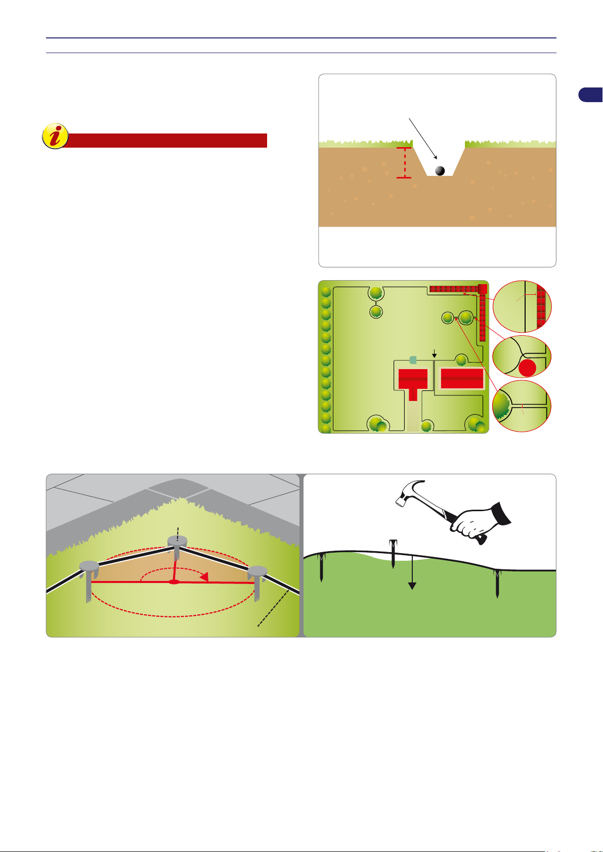
The perimeter wire can be buried or laid on the ground. If you
have a wire layer machine, it is better to bury the wire for greater
protection.
Otherwise, install the wire on the ground with the pegs provided
as described below.
Important
Start laying the perimeter wire from the area where
the charging station is installed, leaving a couple of
extra meters so that it can be cut down to size when
connecting to the power unit during the nal phase.
Ground wire
Cut the grass as low as possible with a grass trimmer or brushcutter
along the entire path where the cable will be laid. This will make it
easier to lay the cable in contact with the ground and reduce the
risk of the robot damaging the insulation.
1. Position the wire in a clockwise direction along the entire path and
secure it with the pegs supplied, making sure there is a maximum
distance of around 100 cm (39.37 inches) between each peg. The
wire must be in contact with the ground to prevent it from being
damaged by the robot before the grass covers it.
EN
35 cm
(13,78 ")
PRIMARY AREA
corridor
< 70 cm (27,56 ")
NO
When laying the perimeter wire, follow the installation
-
direction around the owerbeds, i.e. a counter-clockwise
direction.
In curved sections, secure the wire so that it is not twisted,
-
but curves nicely (radius of 20 cm).
0 cm (0,0 ")
Buried wire
1. Dig an even furrow in the ground (approximately 2-3 cm or 0.787-1.181").
2. Position the wire in a clockwise direction along the track at a depth of a couple of centimetres. Do not bury the wire deeper
than 5 cm, so as not to reduce the quality and intensity of the signal picked up by the robot.
3. During the laying of the wire, it may be necessary to secure it in some points with the pegs provided in order to hold it in place
when covering with the ground.
4. Cover all the wire with soil and make sure it remains taut in the ground.
17
User’s manual
Page 18
Joining of the perimeter wire
3
5
6
4
1 2
protection (L)
current power supply unit
(A)
transmitter (B)
H. min.
160 cm
(63.00 ")
protection (L) transmitter (T)
perimeter wire (M)
connect to the
black terminal
connect to
the red terminal
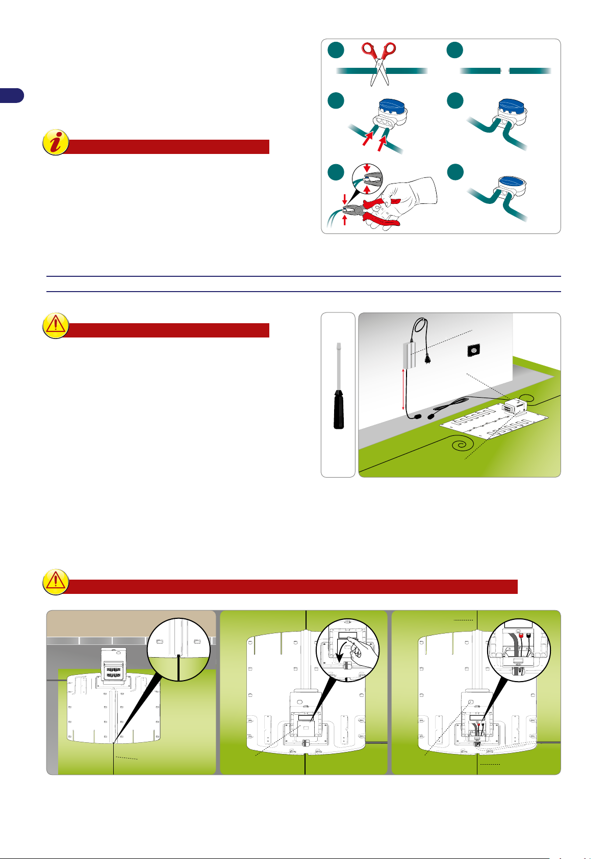
Use an original joint if another perimeter wire is needed to complete
the installation.
EN
Insert each end of the wire in the joint, making sure the wires are
fully inserted so that the ends are visible on each side. Press the
button on the upper side all the way down using a pair of pliers.
Important
For a safe and secure electrical connection,
-
only use original joints.
Do not use insulating tape or other types of
-
joints that do not provide proper isolation
(lugs, terminals, etc.). After some time, soil
moisture causes oxidation and interruption
of the perimeter wire.
INSTALLATION OF THE CHARGING STATION AND POWER SUPPLY UNIT
Warning – Caution
Before carrying out any operations, disconnect the
robot from the mains power.
Position the power supply unit in an area that
cannot be reached by children. For example, at a
height above 160 cm (63 ").
Do not shorten or lengthen the cable getting to the
charging station, wrap as an 8 like form the excess
cord, as shown in the gure.
The perimeter wire used for the installation cannot
be less than 50m, contact the closest customer
service centre .
1. Position the charging station in the predened area.
2. Insert the perimeter wire (M) along the guide in the charging station. Cut the excess perimeter wire to about 5cm above the
connectors.
3. Connect the station incoming wire to red terminal of the transmitter (T). Connect the station outcoming wire to the black
terminal.
The terminals are used only to connect the original perimeter wire.
User’s manual
18
Page 19
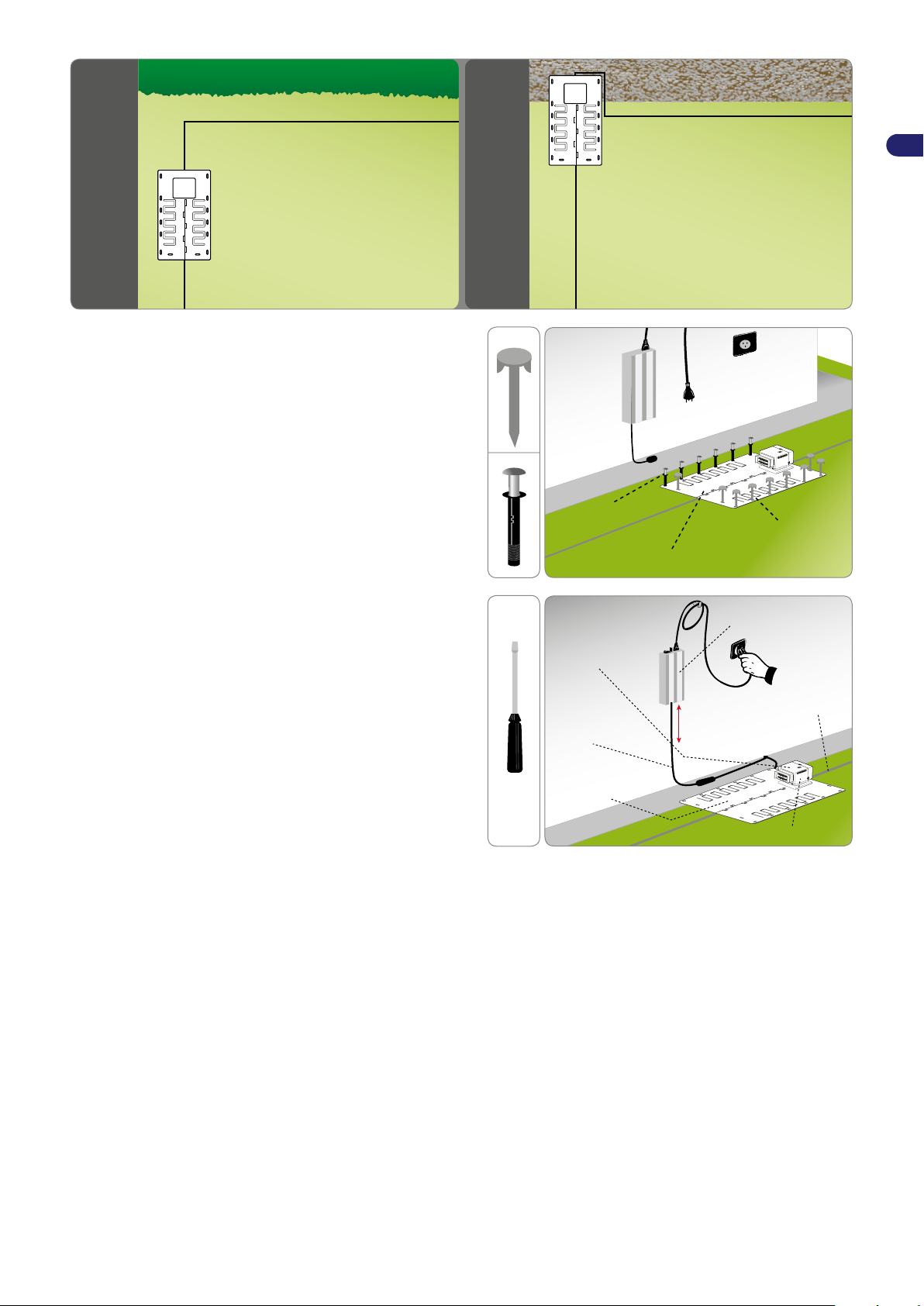
4. Fasten the charging station (N) to the ground with the pegs (P).
pegs (P)
screw anchors (Q)
charging station (N)
current power
supply unit (A)
power cord (E)
Perimeter
wire
charging station (N)
transmitter (B)
H. min. 160 cm
(63.00 ")
protection (L)
(P)
(Q)
If necessary, secure the charging station with screw anchors
(Q).
EN
5. Install the power supply unit (A).
6. Connect the power cord (E) of the charging station (N) to the
power supply unit (A).
7. Connect the plug of the power supply unit (A) to the electrical
outlet.
8. If the LED of the transmitter ashes, the connection is correct.
Otherwise, nd the anomaly (see “Troubleshooting Guide”).
19
User’s manual
Page 20
EN
ADJUSTMENTS
ADJUSTMENT RECOMMENDATIONS
Important
The user must make any adjustments according to the procedures described in this manual. Do not make
any adjustments which are not expressly indicated in this manual. Any special adjustments, not expressly
indicated in this manual, must only be performed by personnel from the Manufacturer’s authorised service
centre.
ADJUSTMENT OF CUTTING HEIGHT
On rst use, set the desired cutting height.
The cutting height is adjusted via the user menu described in the chapter “USE AND OPERATION.”
Important
Do not use the robot to mow grass which is 1 cm (0.40 ") higher than the cutting blade. Reduce the cutting
height gradually. It is recommended to reduce the height by at least 1 cm (0.40 ") every 1-2 days until the ideal
height is reached.
User’s manual
20
Page 21
USE AND OPERATION
(A)
.....................................
......................
10:30
.....................................
......................
10:30
REQUIREMENTS FOR USE
Important
When using the robot for the rst time, carefully read the entire manual and be sure to fully understand
-
it, especially the safety recommendations.
Only use the robot for its intended purpose as described by the Manufacturer. Do not tamper with any
-
device to obtain different operating performances.
Do not use the robot and its peripheral units in bad weather conditions, especially when there is a risk
-
of lightning.
DESCRIPTION OF CONTROL PANEL AND MENU OVERVIEW
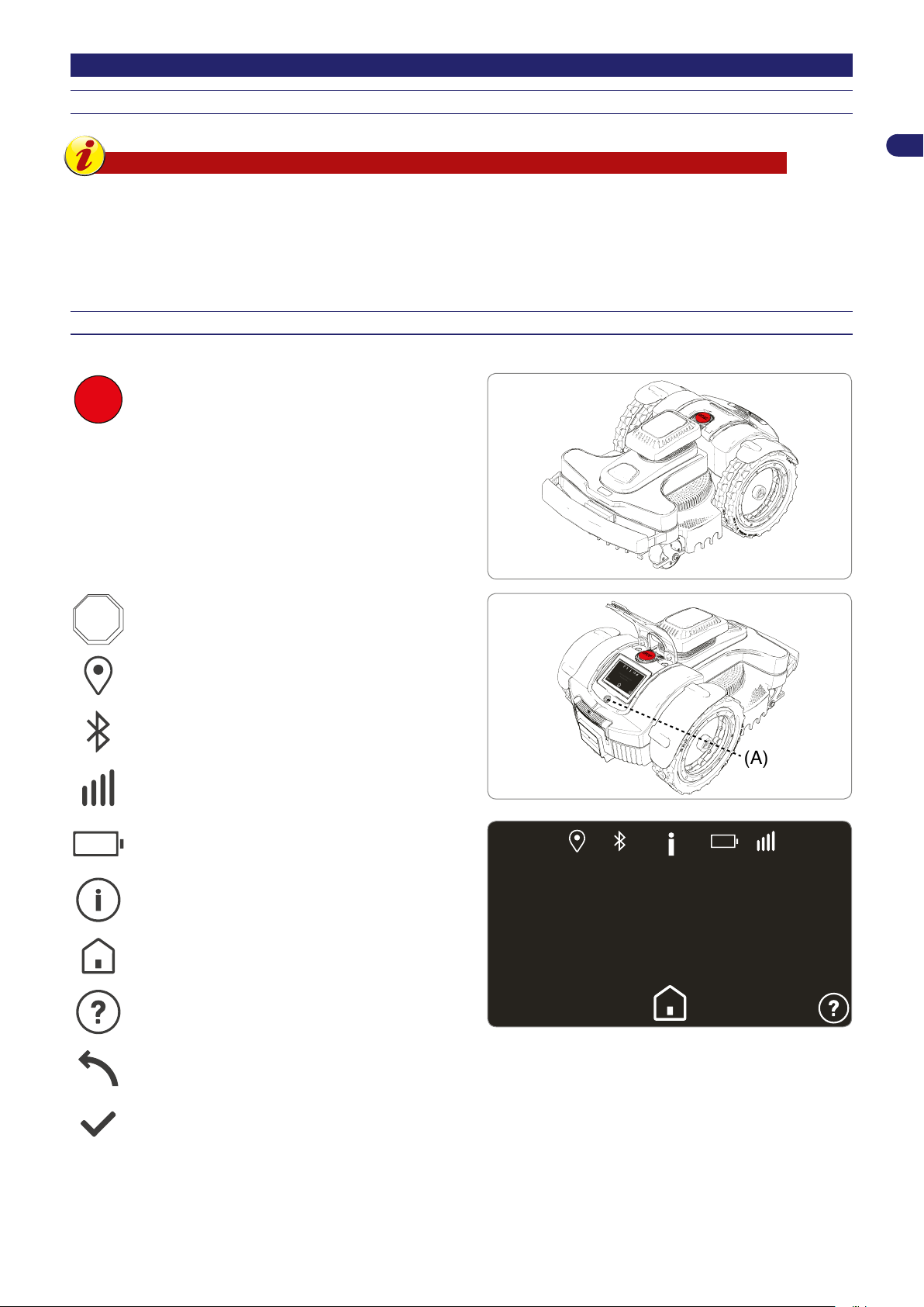
The illustration shows the location and function of the controls on the machine.
STOP.
STOP
Press to stop the robotic mower safely. Only use in
case of imminent danger and to perform maintenance
on the robot.
EN
This is located on the right side of the display and
allows you to turn the robot on or off. (A)
Indicates the status of the GPS receiver.
Indicates the status of the Bluetooth receiver.
Indicates the status of the GPRS receiver for data
transmission.
Indicates the battery charge level.
Robot information. Indicates the version installed and
information on the working times.
Home. Accesses the user menu.
Online help: shows a brief description of the functions
available on the screen.
Goes back to the previous level.
Conrms the operation.
21
User’s manual
Page 22
EN
10:30
10:30
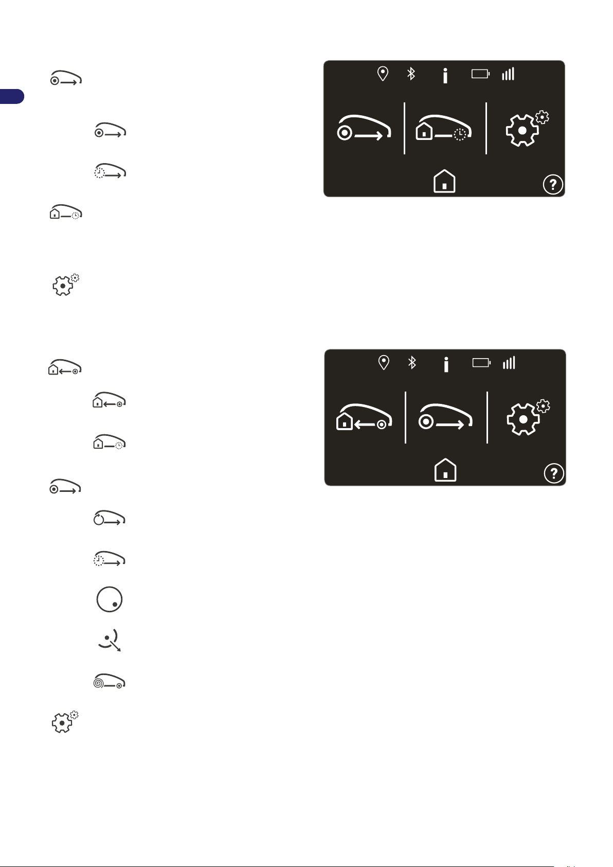
Robot in charging station
"Work"
Immediate start of the work cycle. While the robot is
charging you can select the working area and the time
for re-entry to the charging station.
Starts working immediately.
Allows setting the working area and time for
re-entry to the charging station.
"Pause"
The robot suspends the automatic programming.
You can set the day of the week for resuming the
automatic cycle.
To suspend the work for more than a week, turn off the
robot.
"Settings"
Allows programming the robot. See chapter “Menu
Settings – Programming Mode”
Robot in the garden
"Re-entry"
Immediately returns to the charging station.
Returns to the charging station and
resumes the next work cycle according to
the programming.
Returns to the charging station and stays
there until the day and time of the selected
week.
"Work"
Allows you to select special work functions.
Resumes work.
Works in a selected area until a set time.
Works in a closed area.
Moves away from this area. The robot does
not work within a set radius (available on
models equipped with GPS receiver).
User’s manual
Moves in a spiral pattern to optimise the
mowing in the area where the robot is
located.
"Settings"
Allows programming the robot. See chapter “Menu
Settings – Programming Mode”.
22
Page 23
INITIAL SETUP
10:30
10:30
On rst start-up of the robot, the display will show the initial settings where you can set the language, date, time and some main
parameters of the robot.
Place the robot in the charging station;
-
press the ON/OFF power button;
-
read the safety information before continuing;
-
set the desired language;
-
set the date in the DD/MM/YYYY format and the time in the 24-hour format;
-
follow the prompts in the display to set-up the robot for the rst time.
-
Once the initial set-up process has been completed, you can access the menu settings to change or congure the operating
parameters of the robot according to the characteristics of the mowing area.
MENU ACCESS
EN
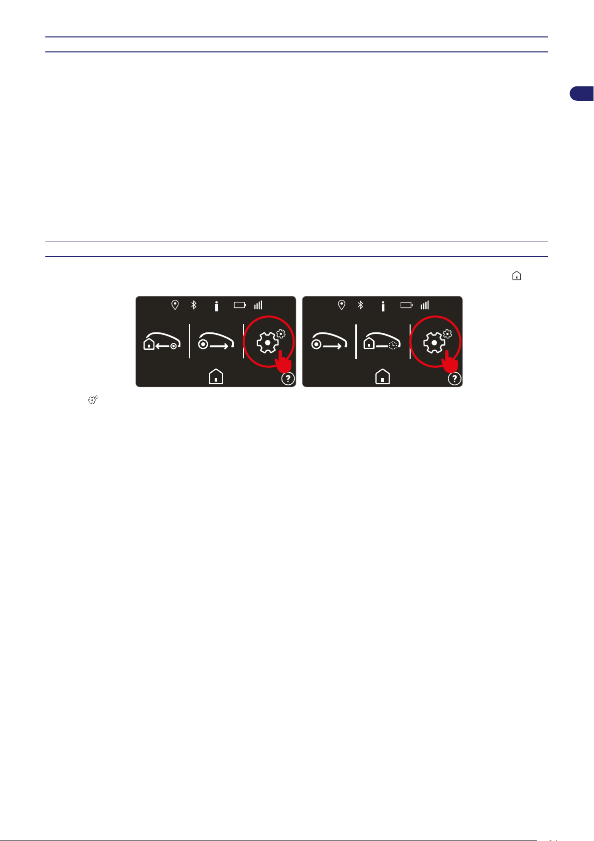
Access the user menu to set the installation and operating parameters of the robot. To access the user menu, press
the robot is in the charging station. Press STOP if the robot is mowing the lawn.
Press the button to access the user menu.
when
23
User’s manual
Page 24
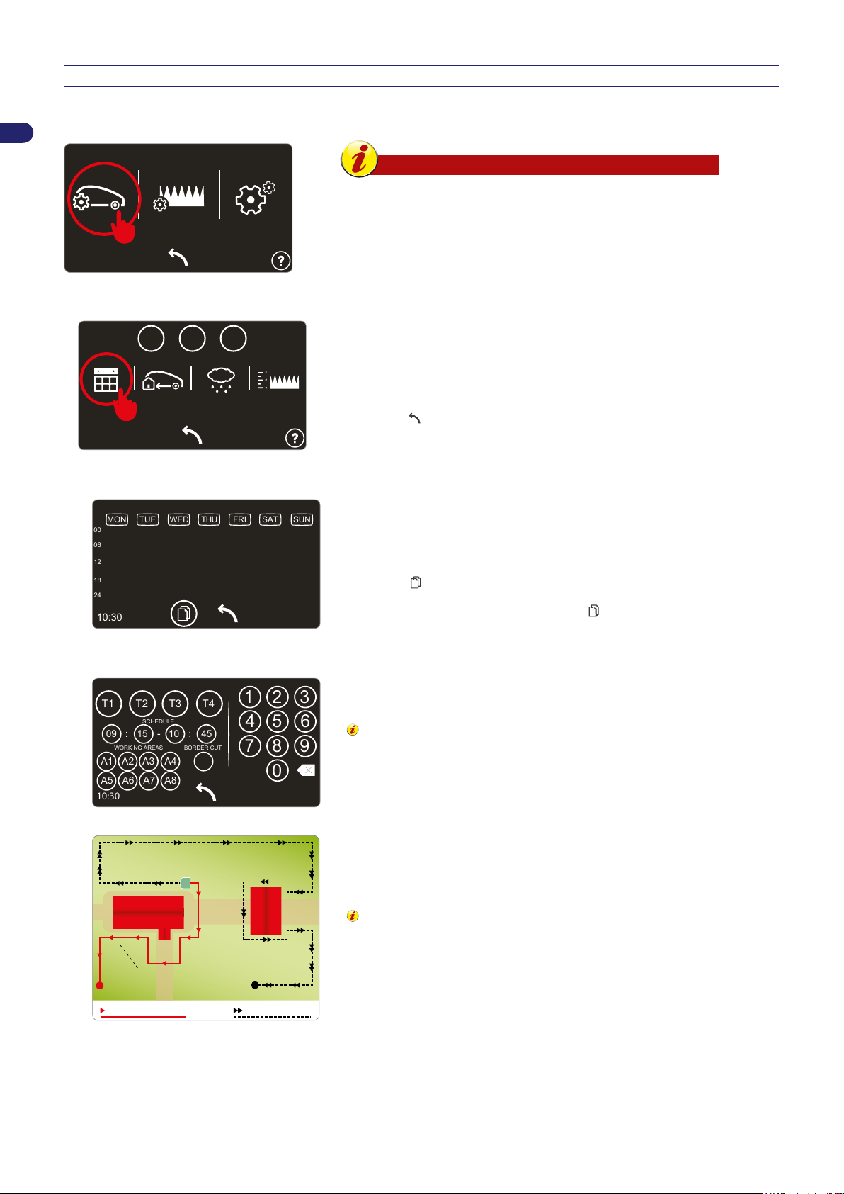
MENU SETTINGS – PROGRAMMING MODE
10:30
10:30
P1
P2
P3
10:30
00
06
12
18
24
MON
TUE WED THU FRI SAT SUN
A1 A2 A3 A4
1 2 3
4 5 6
7 8 9
0
T1 T4T3T2
09
: :
-
15 10 45
WORK NG AREAS
SCHEDULE
BORDER CUT
A5 A6 A7 A8
10:30
primary area
clockwise directionanti-clockwise direction
secondary area 1
(30%, 60MT, clokwise)
secondary area 2
(20%, 30MT, Anti-clokwise)
EN
Robot Programming
Setting of timer
⏎
Work schedule
Important
To get the best out of the robot, it is recommended to
-
program the robot to work every day.
If several working areas need to be set, it is recommended
-
to program at least two working schedules in order to
increase the cutting frequency in the areas.
Three different working proles can be set for using at specic times. This is
particularly useful when you want to use the garden at a different time than
usual.
The last prole set remains highlighted in a different colour and will be active
during the automatic operation of the robot.
Press the
button a few times to go to the main menu.
Up to 4 working schedules can be set for each day of the week.
Press the area of the display corresponding to the day you want to congure,
and then select the times.
⏎⏎
Daily schedule
⏎⏎
PLEASE NOTE: If you want to copy the settings of one day to another, rst
select the , symbol, then the day that you want to copy the settings from,
and then the days one by one that you want to copy the settings to. When you
have nished copying the settings, press
.
For each working schedule (T1,T2,T3,T4) set the start time, end time and the
mowing areas.
Times T1,T2,T3,and T4 must not overlap, the robot will delete
any conicting times.
“Edge cutting”. This function enables the robot to start working by cutting along
the edge of the lawn. This function should be activated at least twice a week.
For example, if you set:
T1: 09:00 - 11:00, A1, A2, A3, A4
T2: 15:00 - 17:00, A1, A2
The robot operating between the hours 15:00-17:00 will perform the mowing
cycle only in the A1 or A2 working area.
The robot can enter areas A3 and A4 when it has to reach a
working area, return to the charging station or work randomly.
The setting of the time is essential for the robot’s proper functioning.
Many parameters inuence the setting of the working schedules,
such as the number of areas, capacity of the batteries, complexity
of the lawn, type of grass, etc. Generally, the working hours must be
increased slightly when mowing gardens with more than one area,
and gardens with lots of obstacles and complicated areas. Below is
a table with the indicative times for conguring the robot on rst use.
User’s manual
24
Page 25
Model m² (ft²) T1 T2 T3
P1
P2
P3
10:30
25
cm50cm75cm
100
cm
0
cm
max
10:30
10:30
P1
P2
P3
10:30
offon
DELAY
10:30
1200 (12912) 10:00 13:00 14:00 15:00
8040EL0
1800 (19418) 09:00 12:00 14:00 17:00
2600 (27976) 08:00 12:00 14:00 18:00
3200 (34432) 08:00 12:00 14:00 18:00 20:00 22:00
3000 (32280) 10:00 13:00 16:00 19:00
4000 (43040) 08:00 11:00 14:00 17:00 20:00 23:00
A041EL0
5000 (53800) 07:30 23:00
6000 (64560) 05:00 23:30
Re-entry to charging station
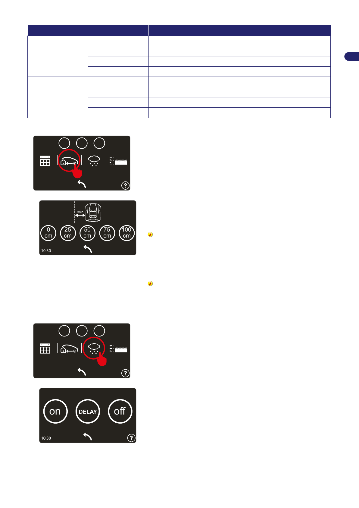
⏎
EN
Sets the distance between the robot and the perimeter wire during its re-entry
to the charging station.
“0 cm”. This setting is recommended for complex gardens with many
obstacles near the perimeter wire and gardens with narrow passages. The
robot will position its wheels on either side of the perimeter wire to return to
the charging station.
⏎⏎
Rain sensor
⏎
Install the perimeter wire using the “On the Wire” method,
refer to the section “Re-entry method to the charging station”
With the remaining parameters the robot returns to the charging station while
maintaining the approximate distance set from the perimeter wire. This option
is recommended for gardens with steep slopes and/or gardens without bumps
near the perimeter wire.
Install the perimeter wire using the “V-Meter” method, refer to
the section “Re-entry method to the charging station”
Sets the behaviour of the robot when the sensor detects rain.
ON: when rain is detected, the robot returns to the charging station. At the end
of the charging cycle, the robot resumes its normal operation if the sensor no
longer detects rain.
⏎⏎
DELAY: when rain is detected, the robot returns to the charging station and
stays there for the time set, which can be congured in the next screen when
the “Delay" button is pressed.
OFF: the rain sensor is turned off.
25
User’s manual
Page 26
EN
P1
P2
P3
10:30
27
mm
10:30
10:30
10:30
A1 A2 A3 A4
A5 A6 A7 A8
6000
DIMENSION
mt
cm
mt
DISTANCE
ECO MODEDIRECTIONDISTANCE WIRE
375
OFF10
1 2 3
4 5 6
7 8 9
0
10:30
primary area
clockwise direction
anti-clockwise direction
secondary area 1
(30%, 60MT, clokwise)
secondary area 2
(20%, 30MT, Anti-clokwise)
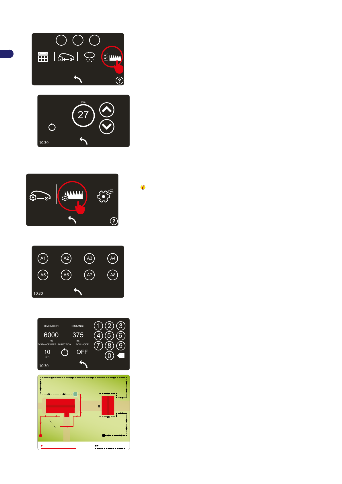
Adjustment of cutting height
Sets the desired cutting height.
⏎
The desired value is set using the arrows.
Press the circular symbol to calibrate the position.
⏎⏎
Garden set up
Sets the characteristics of the mowing zone.
In gardens with one area, at least one zone must still be set.
Setting of work area
⏎
Work schedule
⏎⏎
User’s manual
Up to 8 areas can be set.
Press the area that you want to congure.
2
To disable an area, set the size to 0 m
.
For each area of the garden you must set:
dimension. The indicative size of the work area in square metres;
-
distance. The distance required by the robot to reach the inside of the
-
area by following the perimeter wire. To ensure that the robot starts
working inside the desired area, it is recommended to use the middle of
the work area as a reference for the distance. Set the value to 0 for the
area where the charging station is positioned;
direction. Shortest direction to reach the work area. The direction can
-
be “clockwise” or “counter-clockwise”. On exiting the charging station, the
robot will follow the wire in the set direction;
wire distance. The distance of the robot from the perimeter wire for
-
reaching the work area. Set this value to “0cm” in complex gardens with
many obstacles near the perimeter wire and/or gardens with narrow
passages;
ECO mode. If enabled and the robot detects that the lawn surface has
-
been mowed, the working time in this area is reduced and the robot will
move to the next step.
26
Page 27
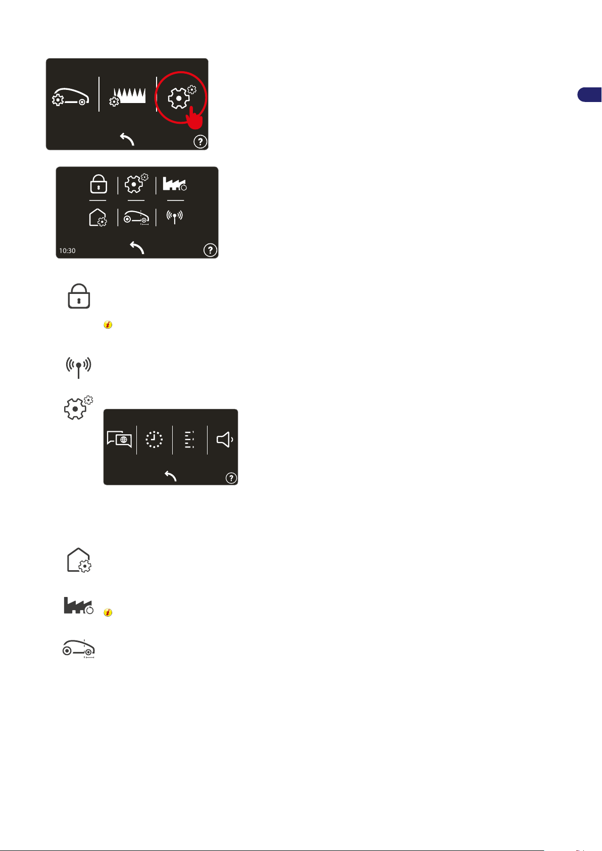
General settings
10:30
10:30
10:30
⏎
Protection. Allows enabling/disabling/changing the robot’s PIN CODE.
To set or change the password, rst enter the current PIN CODE and then the new PIN CODE. Upon purchase,
the password entered by the manufacturer consists of four numbers (“0000”).
Choose a number combination for the password that is easy to remember.
General settings.
EN
Connectivity. (Only in some models). Allows changing the connection parameters.
General settings.
Allows setting the language of the user menu and messages.
-
Allows setting the date and time of the robot.
-
Allows setting the unit of measurement of the distances and areas.
-
Allows turning the sound alerts on and off.
-
This allows setting a correction factor for the alignment and recognition of the charging station. Refer to the robot
menu or the APP for more details.
Resets the factory settings.
All congurations will be lost, the robot and garden settings will have to be congured again. The
PIN CODE will not be reset to the default value.
Sets the distance travelled by the robot after the perimeter wire, before changing direction. Set MIN to allow the
robot to travel the minimum possible distance, MAX for the maximum possible distance and MED for the medium
distance.
27
User’s manual
Page 28
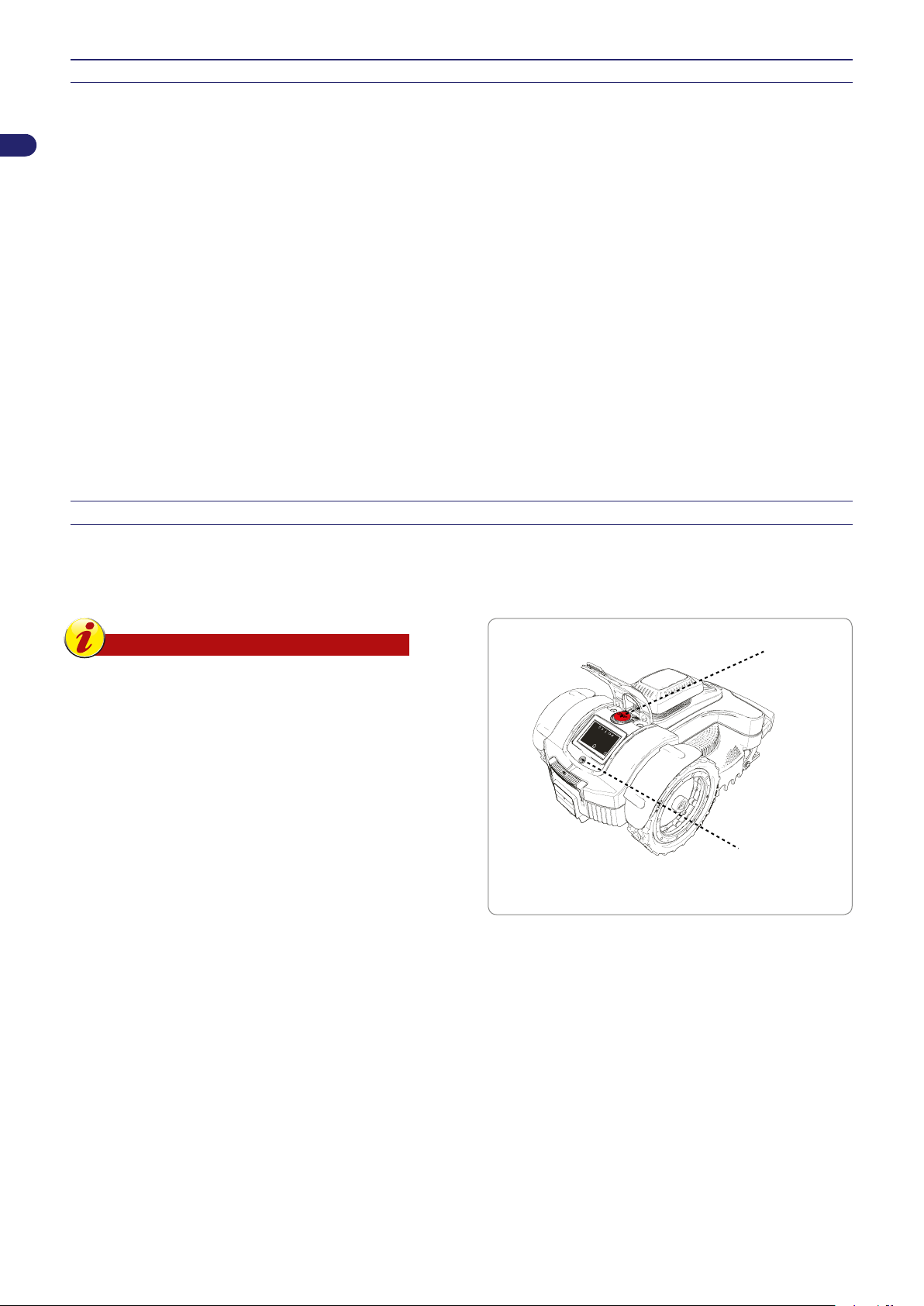
INITIAL START UP – AUTOMATIC MODE
.....................................
......................
10:30
ON/OFF
STOP
The automatic cycle is started during the initial start-up or after a period of inactivity.
EN
1. Check that the height of the lawn surface to mow is compatible with the proper functioning of the robot (see “Technical
Specications”).
2. Adjust the cutting height as desired (see “Adjustment of Cutting Height).
3. Check that the work area has been correctly marked and that there are no impediments to the regular functioning of the robot
as indicated in the section “Preparation and Marking the Boundaries of the Work Areas” and following sections.
4. Position the robot inside the charging station.
5. Press the "ON/OFF" button and wait a few seconds for the robot to turn on completely. Follow the instructions on the display
and enter the password if prompted.
6. If starting the robot for the rst time, it is necessary to program the settings. However, if starting the robot after a long period
of inactivity, check that the programmed functions correspond to the actual condition of the lawn to be mowed (e.g. addition
of a pool, plants, etc.) (See “Programming Mode”).
7. After a few seconds, the message “CHARGING” will appear on the display.
8. The robot starts to mow the lawn according to the modes programmed.
9. Check there are no large puddles after a heavy rain, otherwise the area must be put in order or make sure the robot is in
"Pause".
ROBOT SAFETY STOP
During use, it may be necessary to stop the robot. In normal conditions, the robot can be stopped with the “STOP” key. In case
of danger or when performing any maintenance, it is necessary to stop the robot in safe conditions in order to prevent the blade
from accidently starting. First press the “STOP” button and then the "ON/OFF " button. Disconnect the power plug from the
electrical outlet.
Important
The robot safety stop is necessary during
maintenance and repairs (for example, blade
replacement, cleaning operations, etc.).
To start, proceed as indicated:
position the robot inside the cutting area;
-
press the "ON/OFF" button to turn on the robot and run the
-
start-up procedure again.
If the robot is started up outside of the cutting area, the blade
motor will not start and after briey searching for the signal, the
robot will show "OUT OF BORDER" on the display. Press "ON/
OFF", position the robot inside the cutting area and carry out the
start up procedure again.
User’s manual
28
Page 29
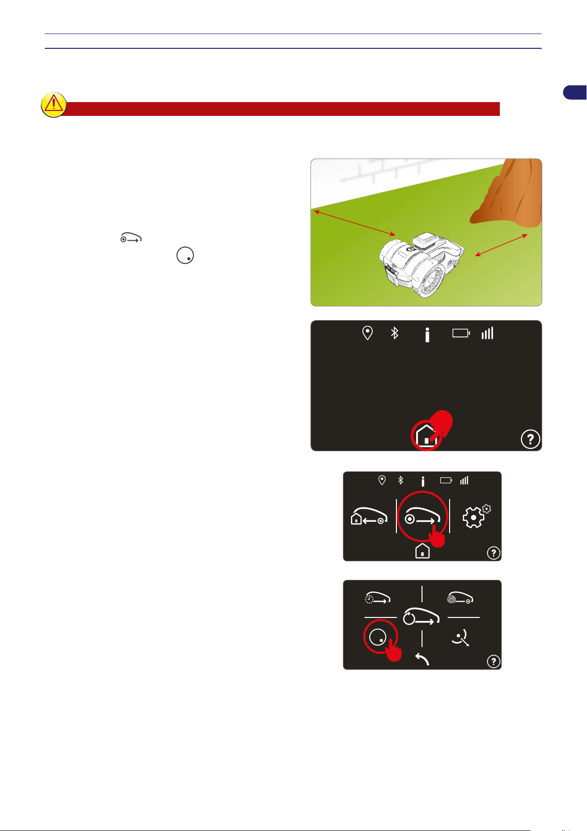
USE OF THE ROBOT IN CLOSED AREAS WITH NO CHARGING STATION
min. 100 cm
(39,37 ")
min. 100 cm
(39,37 ")
.....................................
......................
10:30
10:30
10:30
The start-up of the robot in “closed area” mode is for mowing closed areas that are marked off by the perimeter wire and have
no charging station.
Danger - Attention
Safely stop the robot (see “Robot Safety Stop”) and carry it using the handle provided. Do not grab the robot
by the body and always use the handle provided.
1. Position the robot inside the work area at a minimum distance
of 100 cm (39.37 in.) from the perimeter wire and from any
other obstacles.
2. Press the ON/OFF button and wait a few seconds for the robot
to turn on completely. Follow the instructions in the display and
enter the password, if prompted.
3. Select the key.
4. Select the “closed area” key.
5. Set the time for the end of the working cycle, and select “OK”.
At the end of the working cycle, stop the robot in safe conditions
(see “Robot Safety Stop”) and carry it back to the area where the
charging station is located.
EN
Restore the normal functioning of the robot as described in chapter
“INITIAL START UP – AUTOMATIC MODE.”
29
User’s manual
Page 30
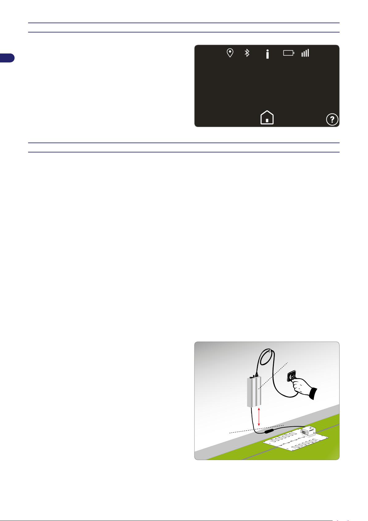
EN
.....................................
......................
10:30
Current power
supplyunit (A)
Charging
station (C)
VISUALISING THE DISPLAY DURING THE WORK PHASE
While in operation, the following data appears on the display of
the robot:
speed of mower;
-
cutting blade speed;
-
percentage of battery charge.
-
While the robot is charging, the display shows the charging level.
If the robot is outside the working time, the display shows the day
and time of the next scheduled start.
PROLONGED INACTIVITY AND RESTARTING
After a long period of inactivity of the robot and before the mowing season, it is necessary to perform a series of operations to
guarantee the correct functioning at the time of reuse.
1. Fully charge the battery before winter storage. Recharge the battery at least once every ve months.
2. Have the routine maintenance performed by an authorised dealer. This is essential for keeping the robot in good condition.
The assistance service usually includes the following operations:
total cleaning of the robot, the cutting blade and all the other moving parts;
•
cleaning of the inside of the robot;
•
checking of robot functioning;
•
checking and, if necessary, replacement of any worn parts such as the cutting blade, the brushes (only in robots equipped
•
with brushed motors);
checking of the battery capacity;
•
if necessary, the dealer may also load new software.
•
3. Accurately clean the robot and charging station (see “Robot Cleaning”).
4. Check any worn or damaged components such as the cutting blade and evaluate their replacement.
5. Store the robot in a protected and dry place with an ambient temperature between 10° and 20° C, out of reach of foreign
elements (children, animals, other foreign objects, etc.). Store the robot at a temperature below 20°C in order reduce the
automatic discharge of the batteries.
6. Disconnect the power plug (A) from the electrical outlet.
7. Cover the charging station (C) to prevent any foreign materials from getting inside (leaves, paper, etc.) and for preserving
the contact plates.
Restarting
Before restarting the robot after a long period of inactivity, proceed
as follows:
1. connect the plug of the power supply unit (A) to the electrical
outlet;
2. reconnect the main electrical power supply;
Restore the normal functioning of the robot as described in chapter
“INITIAL START UP – AUTOMATIC MODE.”.
User’s manual
30
Page 31
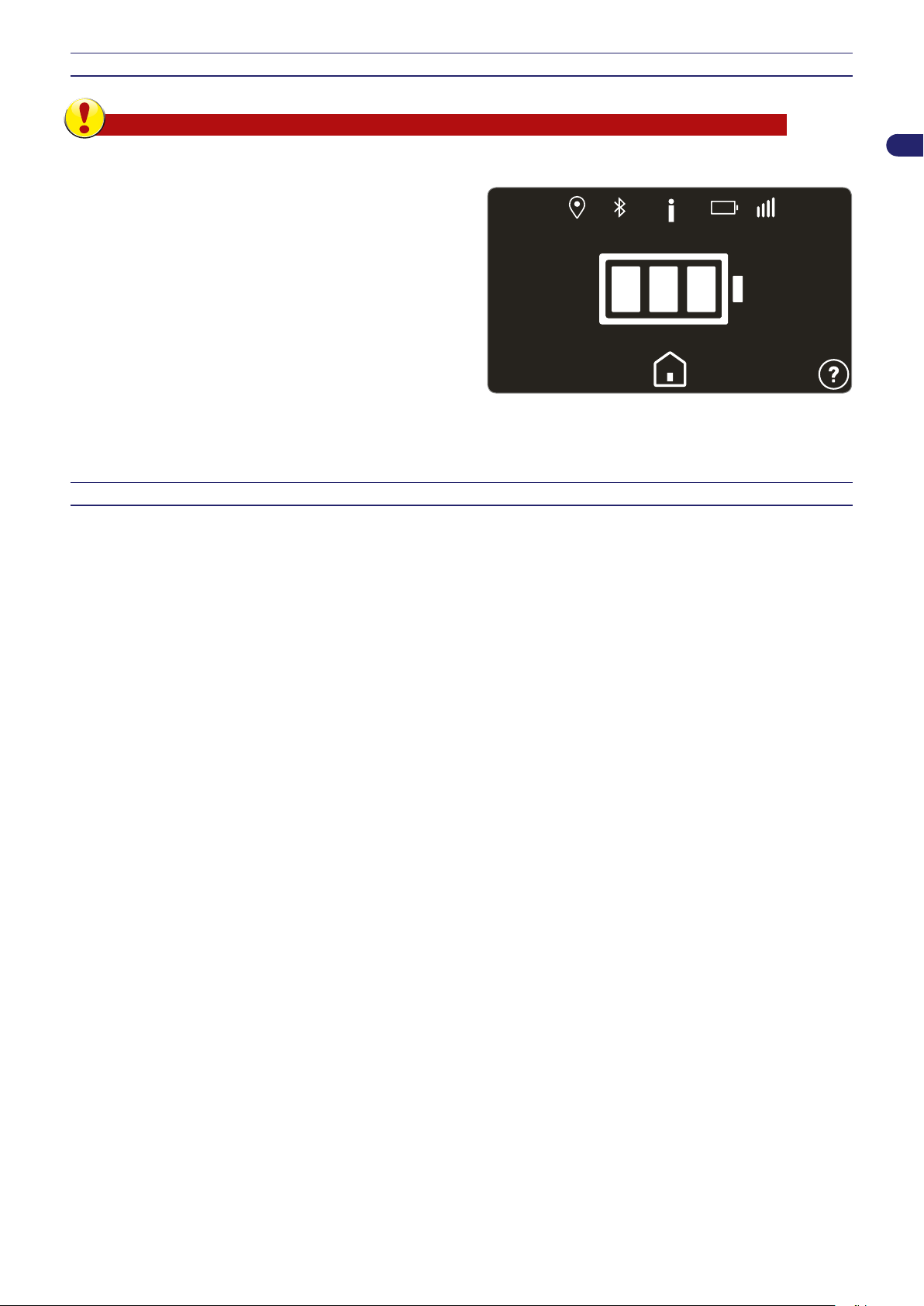
BATTERY CHARGING AFTER PROLONGED INACTIVITY
10:30
Danger - Attention
Do not recharge the robot in explosive and ammable environments.
1. Supply electricity to the charging station and make sure the
charging plates are clean.
2. Position the robot inside the charging station without turning
it on.
3. Check that the charging knobs are in contact with the charging
plates and that the display turns on indicating the battery’s
charging level .
4. At the end of the charging cycle (about 6 hours) remove the
robot from the charging station.
5. Store the robot in a protected and dry place with an ambient
temperature between 10°C and 20°C, out of reach of children,
pets, other foreign objects, etc.
OPERATING TIPS
EN
Below are some useful operating tips to follow when using the robot:
even after being suitably informed on the use of the robot, it is always a good idea to simulate some test manoeuvres on rst
-
use to identify the commands and main functions;
check and secure the fastening screws of the main components;
-
mow the lawn frequently to avoid excessive growth of the grass;
-
do not use the robot to mow grass which is 1 cm (0.40 ") higher than the cutting blade. In case of high grass, lift the cutting
-
blade and then lower it gradually on the following days;
if the lawn is equipped with an automatic sprinkler system, program the robot to return to the charging system at least one
-
hour before the sprinklers are turned on;
check the slope of the ground and make sure the maximum values allowed are not exceeded in order to prevent damage to
-
the robot and the sprinklers;
it is recommended to program the robot so that it does not work more than is necessary, also taking into consideration the
-
different growth rates of the grass in different seasons, so as not to subject it to unnecessary deterioration and reduction of
the battery life;
when using the robot, make sure the work area is clear of people (in particular, children, the elderly or disabled people) and
-
pets in order to prevent safety risks. To minimise the chance of injury, program the robot so that it operates at suitable times
of the day.
The manufacturer does not guarantee complete compatibility between the robotic mower and other types of wireless systems,
such as remote controls, radio transmitters, acoustic aids, underground electric fences for animals or the like.
31
User’s manual
Page 32

EN
ROUTINE MAINTENANCE
MAINTENANCE RECOMMANDATIONS
Important
During maintenance, use personal protection equipment indicated by the Manufacturer, especially when
working on the blade. Before carrying out any type of maintenance, make sure the robot is turned off (see
“Robot Safety Stop”).
SCHEDULED MAINTENANCE TABLE
Frequency Part Type of maintenance Reference
Clean and check the
Blade
Battery charging knobs
Weekly
Monthly Robot Clean the robot See “Robot Cleaning”
Once a year and at the end
of the mowing season
(in models with contact
charging)
Contact plates
(in models with contact
charging)
Rain sensor Clean and remove any rust See “Robot Cleaning”
Robot
efciency of the blade. If the
blade is bent or very worn,
replace it
Clean and remove any rust See “Robot Cleaning”
Clean and remove any rust See “Robot Cleaning”
Have the robot serviced
at an authorised service
centre
See “Robot Cleaning”
See “Blade Replacement”
See “Prolonged inactivity
and restarting
User’s manual
32
Page 33
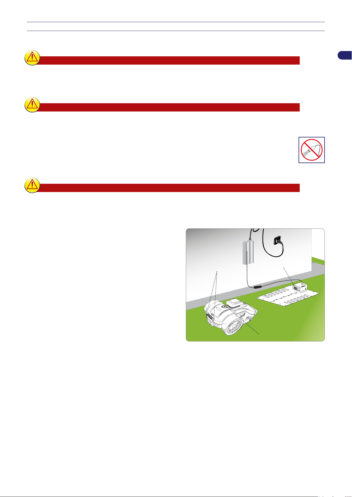
1. Stop the robot safely (see “Robot Safety Stop”).
charging knobs (A)
contact plates (B)
rain sensor (C)
ROBOT CLEANING
Warning – Caution
Use protective gloves to prevent cutting your hands.
2. Clean all the outside surfaces of the robot with a sponge soaked in warm water and a mild detergent. Squeeze well to remove
any excess water before use.
Warning – Caution
The use of too much water may cause water to penetrate into the device which could damage the electrical
parts.
3. Do not use solvents or benzene so as not to damage the painted surfaces and plastic components.
4. Do not wash the inside parts of the robot and do not use jets of pressurised water so as not to damage the
electric and electronic parts.
Warning – Caution
In order to avoid irreversible damage to the electric and electronic components, do not immerse the robot,
partially or completely, in water because it is not watertight.
EN
5. Check the lower part of the robot (cutting blade area, and
wheels), use a brush suitable to remove deposits and/or
residues that may impede the proper functioning of the robot.
6. Remove any grass and leaves from the gripping areas of the
robot.
7. (In models with contact charging) Clean the knobs of the
battery charger (A), the contact plates (B) and remove any
deposits or residuals caused by electric contacts with a dry
cloth and, if necessary, with ne sandpaper.
8. Clean the rain sensor (C) and remove any dirt or rust.
9. Clean the inside of the charging station to remove any
accumulated residuals.
33
User’s manual
Page 34
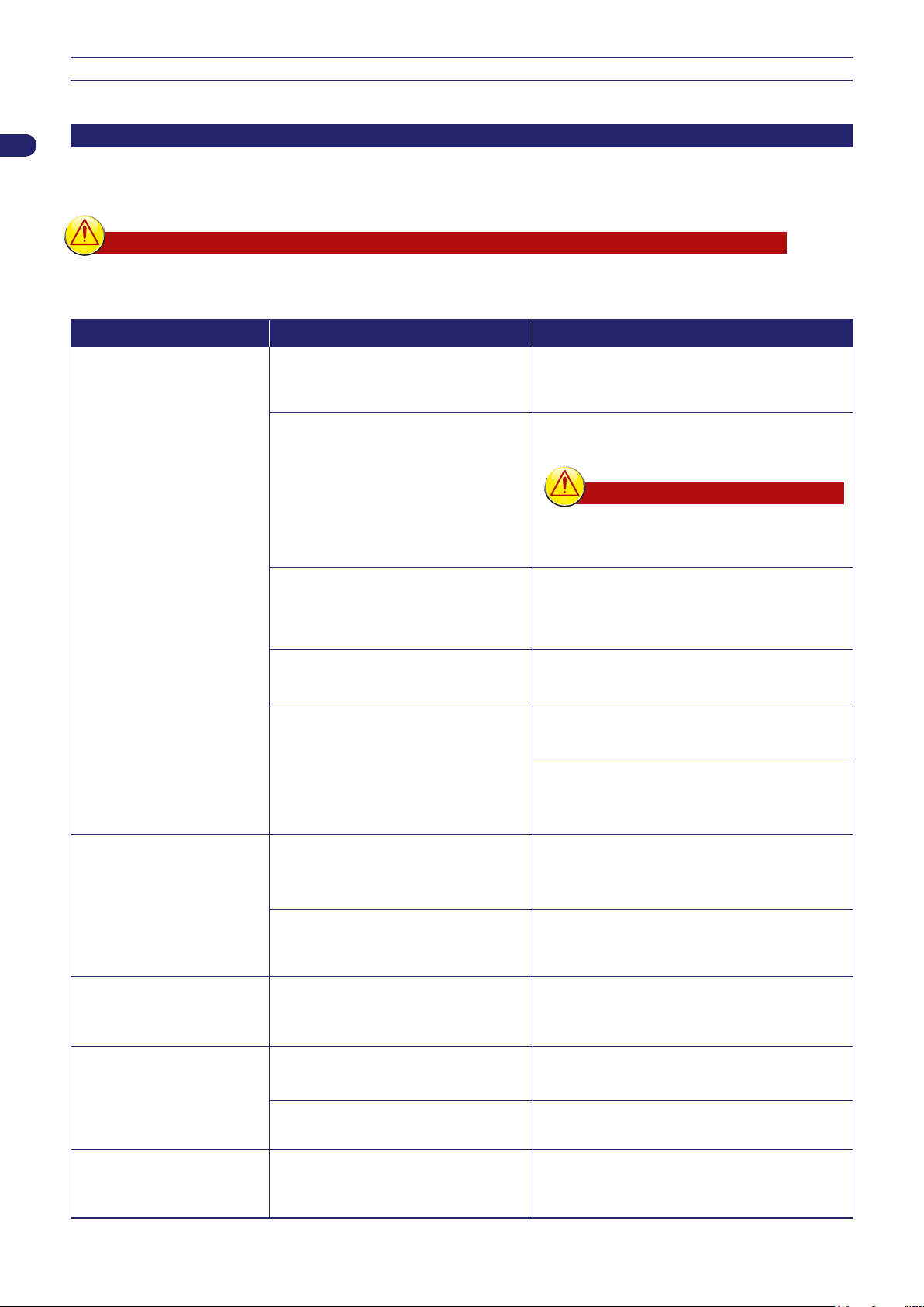
TROUBLESHOOTING
EN
TROUBLESHOOTING GUIDE
The information below is designed to help identify and correct any faults and/or malfunctions which may occur during operation.
Some faults can be xed by the user, while others require specic technical skills or special expertise and therefore must only be
xed by qualied personnel with certied experience in the specic eld of intervention.
Warning – Caution
Safely stop the robot (see “Robot Safety Stop”) in case it is necessary to check the robot, in order to avoid
danger of accidental blade starting.
Problem Cause Remedies
Replace the blade with a new one (see “Blade
Replacement”)
Safely stop the robot (see “Robot Safety Stop”).
Unclog the blade
Warning – Caution
Use protective gloves to prevent injuries to
your hands
Stop the robot safely (see “Robot Safety Stop”)
Remove the obstacle and restart the robot (see
“Start up - Automatic mode”)
Abnormal vibrations
The robot is very noisy
Cutting blade damaged
Cutting blade clogged by residuals
(tape, cords, plastic fragments, etc.)
The robot was started in the presence
of obstacles (fallen branches, forgotten
objects, etc.)
The robot does not position
itself correctly inside the
charging station
The robot does not behave
correctly around the
owerbeds
The robot works at the wrong
time
Electric motor failure
Grass too high
Incorrect positioning of the perimeter
wire or power cord of the charging
station
Collapsing of ground next to the
charging station
Perimeter wire laid incorrectly
Clock was set incorrectly
Working time was set incorrectly
Have the motor replaced or repaired by your
nearest authorised service centre
Increase the cutting height (see “Adjustment of
cutting height”)
Carry out a preliminary cutting of the area with a
normal lawnmower
Check the connection of the charging station
(see “Installation of charging station and power
supply unit”)
Position the charging station on a at and stable
surface (see “Planning of system installation”)
Reposition the perimeter wire correctly (counter-
clockwise direction) (see “Installation of
perimeter wire”)
Reset the clock of the robot (see “Programming
Mode”)
Reset the working time (see “Programming
Mode”)
The robot does not execute
quick re-entry
User’s manual
Quick re-entry not setup correctly
34
Check the exact layout of the quick re-entry
(see “Layout of the robot’s quick re-entry to the
charging station”)
Page 35

Problem Cause Remedies
The work area is not
completely mowed
Not enough work hours
Cutting blade clogged with deposits
and/or residuals
Cutting blade worn out
Work area too big compared to the
actual capacity of the robot
The batteries are about to run out.
The batteries do not charge completely
Extend the working time (see “Programming
Mode”)
EN
Stop the robot safely (see “Robot Safety Stop”)
Warning – Caution
Use protective gloves to prevent injuries to
your hands.
Clean the cutting blade
Replace the blade with an original spare part
(see “Blade replacement”)
Adjust the work area (see “Technical
specications”)
Replace the batteries with original spare parts
(see “Battery replacement”)
Clean and remove any rust from the contact
points of the batteries (see “Robot Cleaning”).
Secondary area not
completely mowed
“Service” appears on the
“Lift” appears on the display The robot is lifted from the ground
“No Signal” appears on the
display
display
The perimeter wire is not connected
correctly (broken cable, no electrical
Programming error
The robot needs to be serviced Contact your nearest authorised service centre
connection, etc.)
Too much slope
Perimeter wire laid incorrectly
Correctly program the secondary area (see
“Programming Mode”)
Check that the robot is not blocked or obstructed
by any objects.
Clean and eliminate any residual grass under
the body shell which may obstruct the sensors
(see "Robot cleaning")
Check the functioning of the electrical power
supply, the correct connection of the power
supply unit and of the charging station (see
“Installation of charging station and power supply
unit”)
Delimit the area with too much slope (see
“Planning of system installation”)
Check that the wire has been installed correctly
(too deep, next to metallic objects, distance
between the wire marking the two elements
less than 70 cm, etc.) (see “Planning of system
installation”)
“Out of border” appears on
the display
Perimeter wire marking the boundary of
the inside areas (owerbeds, bushes,
etc.) laid in a counter-clockwise
direction
Overheated power supply unit
Incorrect wheel transmission
35
Reposition the perimeter wire correctly (counter-
clockwise direction) (see “Installation of
perimeter wire”)
Adopt the appropriate measures to reduce the
temperature of the power supply unit (ventilate
or modify the installation area, etc.) (see
“Planning of system installation”)
Check and, if necessary, correctly fasten the
wheels
User’s manual
Page 36
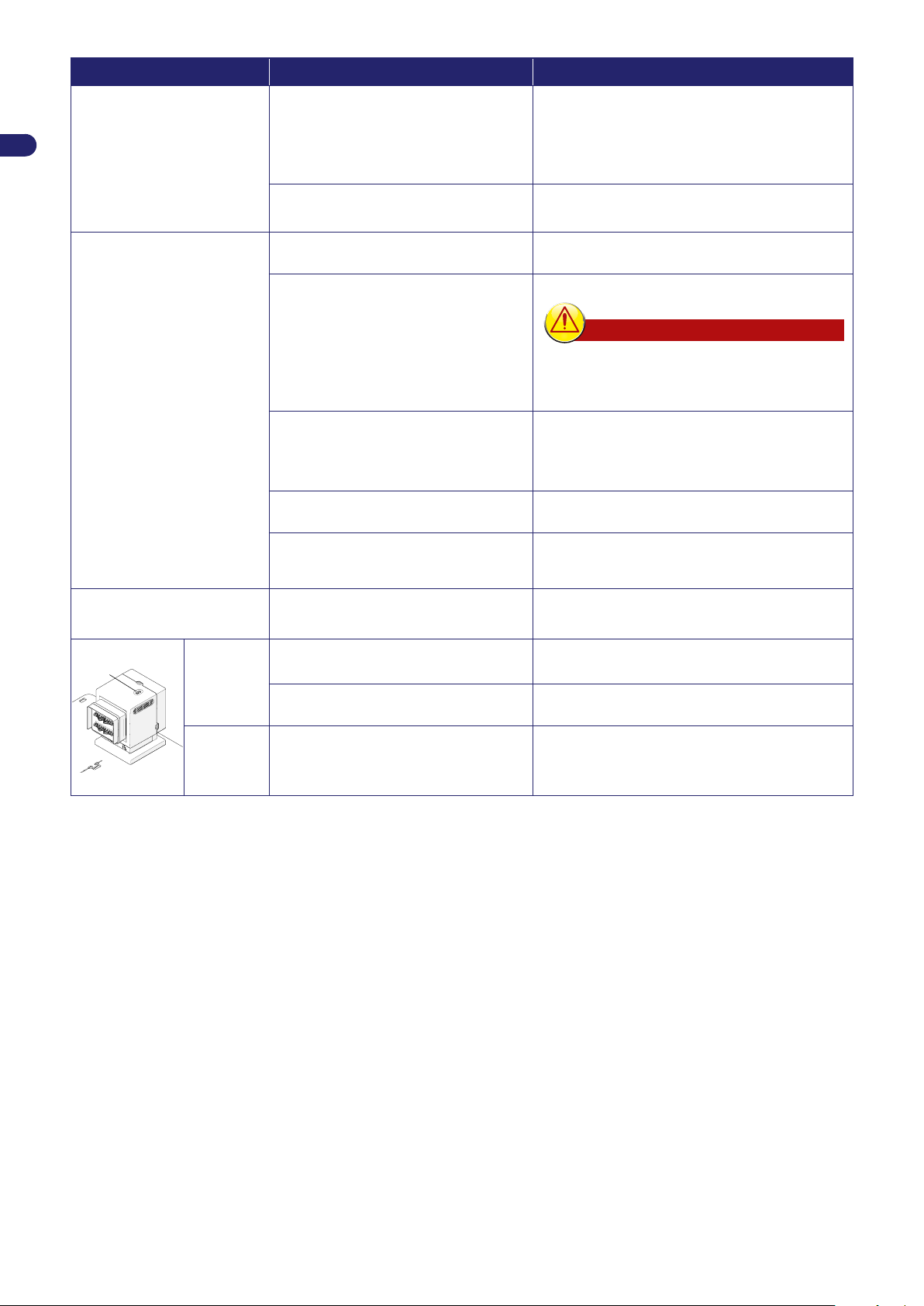
EN
Problem Cause Remedies
“Wheel error” appears on the
display
Ground is uneven or contains obstacles
that prevent movement
Make sure the lawn to be mowed is even
and does not contain holes, stones or other
obstacles. Otherwise, ll in any holes and
remove any obstacles (see “Preparation and
marking the boundaries of the work areas
(primary and secondary areas)”)
“Too high grass” or
“Blade Error”appears on the
display
“Tilt” appears on the display
Failure of one or both motors that
operate the transmission of the wheels
Cutting blade damaged
Cutting blade clogged by residuals
(tape, cords, plastic fragments, etc.)
The robot was started in the presence
of obstacles (fallen branches, forgotten
objects, etc.)
Electric motor failure
Grass too high
The robot is located on a slope that is
higher than the allowed limits
Have the motor replaced or repaired by your
nearest authorised service centre
Replace the blade with a new one (see “Blade
Replacement”)
Stop the robot safely (see “Robot Safety Stop”)
Warning – Caution
Use protective gloves to prevent injuries to
your hands
Unclog the blade
Stop the robot safely (see “Robot Safety Stop”)
Remove the obstacles and restart the robot (see
“Start up - Automatic mode”)
Have the motor replaced or repaired by your
nearest authorised service centre
Increase the cutting height (see “Adjustment of
Cutting Height”). Perform a preliminary cutting of
the area with a normal lawnmower
Mark off the area that is too steep
(C)
The led
(c) does
not turn on
The
transmitter
LED (C)
is on
No power supply
Interrupted fuse
Interrupted perimeter wire
Make sure the power supply unit is correctly
connected to the power outlet
Have the fuse replaced by your nearest
authorised service centre
Stop the robot safely (see “Robot Safety Stop”).
Disconnect the power plug from the power
supply unit. Join the perimeter wire
User’s manual
36
Page 37
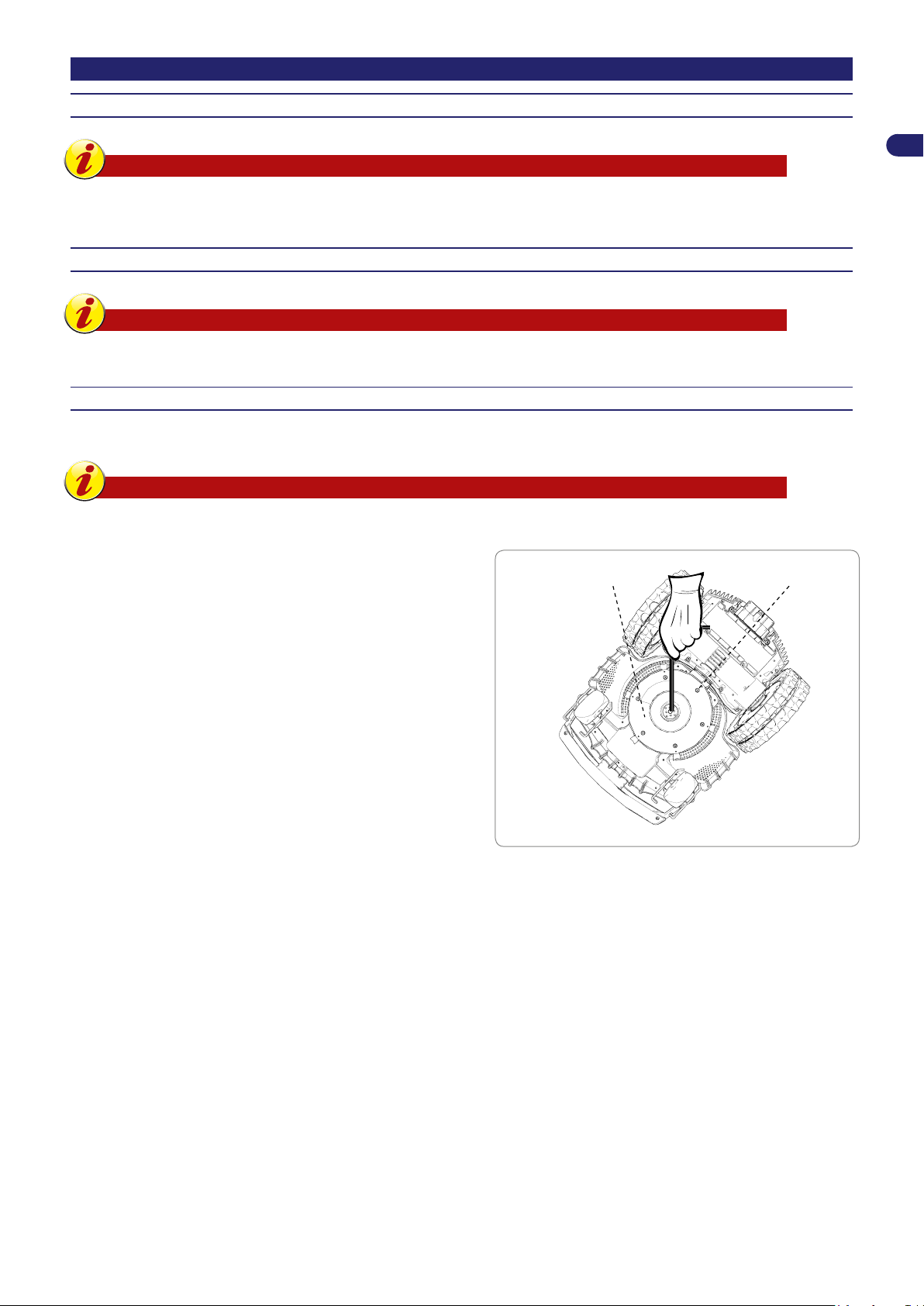
PART REPLACEMENT
blade (A)
screws (B)
RECOMMENDATIONS FOR REPLACING PARTS
Important
Replace and repair any parts according to the manufacturer’s instructions, or contact the service centre if
these operations are not included in the manual.
BATTERY REPLACEMENT
Important
Replace the batteries at an authorised service centre.
BLADE REPLACEMENT
1. Stop the robot safely (see “Robot Safety Stop”).
Important
Use protective gloves to prevent injuries to your hands.
EN
For replacement, use only the original blade suitable for the device.
Model Cutting blade code
8040EL0 042Z54300A
A041EL0 300_D0042_04
2. Turn the robot over and position it so as not to ruin the covering
hood.
3. Unscrew the screws (B) to remove the blade (A).
4. Insert a new blade and fasten the screws.
5. Turn the robot back over to its operating position.
37
User’s manual
Page 38
EN
ROBOT DISPOSAL
At the end of its useful lifespan, this product is classied as WEEE (waste electrical and electronic
•
equipment). It must therefore not be disposed of as normal domestic waste, as mixed urban waste
(undifferentiated) or as separated urban waste (differentiated).
When it is time for disposal, the user must make sure that the product is recycled in compliance with the
•
requirements of the local laws; in particular, electric and electronic components must be separated and
sorted in authorised waste disposal centres for WEEE, or the product must be taken intact to the dealer
when a new purchase is made. Abusive disposal of WEEE is punished by nes established by laws in force
in the areas where said disposal occurs.
Dangerous substances contained in electric and electronic equipment have potentially harmful effects on
•
the environment and people’s health so the user has a fundamental role in contributing to reuse, recycling
and any other way of recovering WEEE.
All parts, to be specically separated and disposed of, are marked..
•
Danger - Attention
WEEE - Waste Electric and Electronic Equipment (WEEE) can contain dangerous substances with potentially
harmful effects on the environment and people's health. WEEE must be disposed of correctly and only in
specic disposal centres.
Packaging - Product packaging is made with recyclable materials and must be disposed of in a sustainable manner in special
•
disposal containers or authorised waste disposal centres.
Batteries - Old or exhausted batteries contain harmful substances for the environment and people's health so must not
•
be disposed of as normal domestic waste. The user must dispose of batteries in a sustainable way, in specic disposal
containers or in authorised waste disposal centres.
User’s manual
38
Page 39

EC DECLARATION OF CONFORMITY
ZUCCHETTI Centro Sistemi S.p.A. Via Lungarno 305/A Terranuova B.ni (AR) ITALY
Declares and assumes liability that the product:
battery-powered automatic lawnmower robot, model 8040EL0, A041EL0 complies with the basic requisites for safety, health
and environmental protection provided for by the following European Union directives:
Machinery directive 2006/42/EC, electromagnetic compatibility directive 2014/30/EU, Radio (RED) directive 2014/53/UE,
RoHS directive 2011/65/EU, WEEE directive 2012/19/EU, directive for noise emission in the environment 2005/88/EC;
complies with the following harmonised standards:
EN 50636-2-107:2015 + A1:2018 and EN 60335-1:2012 + AC:2014 + A11:2014 + A13:2017 (safety);
EN 62233:2008 (electromagnetic elds);
EN 55014-1:2017 (emission);
EN 61000-3-2:2014 and EN 61000-3-3:2013 (emission);
EN 55014-2:2015 (immunity);
EN 50419:2006 (WEEE – Equipment marking)
ETSI EN 301 489-1 V2.1.1 (Electromagnetic compatibility)
ETSI EN 301 489-17 V3.1.1 (Electromagnetic compatibility)
ETSI EN 300 328 V2.1.1 (Radio Spectrum Efciency)
ETSI EN 303 447 V1.1.1 (Radio Spectrum Efciency)
Models equipped with ”Connect module (GPS, GPRS)”:
ETSI EN 301 511 V12.5.1 (Radio Spectrum Efciency)
also declares that, pursuant to directive 2005/88/EC, the LWA sound power level, out of a signicant sample is 63.0 dB ± 2.0
dB (weighted on A curve and referred to 1 pW), that the guaranteed LWA sound power level is less than 67 dB (weighted on
A curve and referred to 1 pW) and that the technical folders in compliance with directives 2005/88/EC and 2006/42/EC are
available c/o Zucchetti Centro Sistemi S.p.A. via Lungarno 305/a, Terranuova B.ni (ar), Italy.
EN
Terranuova B.ni 05/10/2020
Bernini Fabrizio
(CEO)
39
User’s manual
Page 40

WARRANTY RULES
Zucchetti Centro Sistemi S.p.A (ZCS) ensures application of all the requirements of European Directive 1999/44/CE. In particular,
the warranty covers any material or manufacturing defects for a period of 2 (two) years from the original date of purchase.
ZCS does not warrant uninterrupted or error-free operation of the product, nor shall it be liable for damage caused by the
failure to follow instructions. Furthermore, this warranty does not cover aesthetic damage, such as scratches, nicks and dents;
consumable materials such as batteries, unless the damage was caused by a defect in materials or workmanship; damage
caused by the use of the product with accessories not manufactured or sold by ZCS; damage caused by accidents, abuse,
misuse, oods, re or other natural events or external causes; damage caused by operations performed by service providers not
authorised by ZCS; or damage to a product that has been modied or altered without the written permission of ZCS.
ZCS shall have the exclusive right to repair or replace (with a new or refurbished product) the product or components or to offer,
at its sole discretion, full refund or the purchase price. When a refund is given, the product for which you received the refund must
be returned to ZCS and it becomes the property of ZCS.
During the warranty period, ZCS shall, at its sole discretion, see to repairing or replacing any parts that fail in normal use. The
repair or replacement may include the use of newly manufactured or refurbished used parts as ZCS sees t. ZCS also has
the right to use replacement units, parts or components of similar value and design. The cost of parts or labour for repairs or
replacements will not be charged to the customer, who instead will be charged for the shipping costs. When replacing a product
or part, any replacement element becomes the property of the user and the replaced part becomes the property of ZCS,
depending on the case.
This warranty does not affect the legal rights of customers under applicable state or national laws, except for charges established
by these laws to be borne by the customer to enforce this warranty.
The warranty is limited to the country of purchase and is enforced at the retail outlet where the robot was purchased or at your
nearest service centre. The faulty robot must be returned in person to your vendor or to your nearest service centre. In the case
of delivery by courier, to be paid by the purchaser, the robot must be packed in its original packaging and accompanied by a copy
of the invoice or purchase receipt, including the date of purchase, serial number and description of the problem.
CONDITIONS AND LIMITATIONS
For the application methods of this warranty and for any
•
information, contact your dealer.
This warranty is valid only if:
•
the faulty product is brought back with the original legible
-
invoice or purchase receipt showing the purchase date
and name of the dealer.
This warranty is void if:
•
the product has not been used according to the
-
instructions of use and maintenance;
the installation or use did not comply with the instructions
-
of use;
the serial number has been cancelled or made illegible;
-
any unauthorised peripheral device has been used or
-
the product has been modied;
unoriginal spare parts or accessories have been used;
-
a part or an accessory has been tampered with;
-
maintenance has been performed by the customer or
-
by unauthorised third parties;
the robot, power supply unit, charging station or
-
accessories has faults caused by atmospheric agents
such as lightning, avalanches, landslides, power
surges, storms, oods, natural disasters, etc.
Excluded from the warranty and limitations:
•
the warranty does not cover parts subject to wear
-
following use, such as brushes, cutting blades,
perimeter wire, pegs, belts, wheels, blades, cables and
connection cords;
external parts and plastic supports that do not present
-
manufacturing defects. Discoloration of plastic due to
natural reasons or chemicals;
the battery warranty is limited only to manufacturing
-
defects in the rst six months of life;
the motors have a warranty of 2 years with limit at 3000
-
working hours.
HOW TO REQUEST WARRANTY SERVICE
To request warranty service and specic instructions on
where and how to return the ZCS product for service, contact
the dealer where you purchased the robot or your nearest
service centre. To enforce the warranty right, the customer
must present an original or a copy of the invoice or purchase
receipt of the product issued by the original dealer. The limited
warranty is only valid and enforceable in the country where
ZCS or its authorised dealers originally sold the product.
ADDITIONAL DEFINITIONS
On-site support
The customer is not entitled to on-site support of the
•
product, not even during the warranty period.
Should on-site support be necessary, the call and the
•
hourly rate applied by the service centre will be charged
to the customer.
Suggestions
Keep the original packaging.
•
Keep the invoice or purchase receipt (cause for loss of
•
warranty).
Please note
The customer is obliged to carefully read the instruction
•
booklet and to follow all the information contained in it.
 Loading...