

Page 1

ASSEMBLY, INSTALLATION & SERVICING
ANUAL FOR AMBIRAD VISION
M
ANGE OF RADIANT TUBE HEATERS
R
®
VSX
INDEX Section
Introduction and Document Index
Installation Requirements-------------------------------------------------1
Assembly Instructions------------------------------------------------------2
Commissioning Instructions----------------------------------------------3
Servicing Instructions------------------------------------------------------4
Spare Parts-------------------------------------------------------------------5
Fault Finding Guide --------------------------------------------------------6
Replacing Parts -------------------------------------------------------------7
User and Operating Instructions ----------------------------------------8
WARNINGS
AmbiRad equipment must be installed and maintained in accordance with the relevant
provisions of the Gas Safety (Installations and Use) Regulations 1998 for gas fired products.
Due account should also be taken of any obligations arising from the Health and Safety at
Works Act 1974 or relevant codes of practice. In addition the installation must be carried out
in accordance with the current IEE wiring regulations (BS 7671), BS 6896 (Industrial &
Commercial) and any other relevant British Standards and Codes of Practice by a qualified
installer. All external wiring MUST comply with the current IEE wiring regulations.
Page 2

2 3
Page 3

Introduction.
Welcome to the new range of high efficiency
AmbiRad Vision radiant tube heaters. Local
regulations may vary in the country of use and
it is the installers responsibility to ensure that
such regulations are satisfied.
All installation, assembly, commissioning and
service procedures must be carried out by
suitable qualified competent persons to the
statutory regulations in the country of use.
When assembling, installing, commissioning
and servicing is undertaken on radiant tube
heaters specified in these instructions, due care
Document Index.
1 Installation Requirements
1.1 Health & Safety
1.2 Model Definitions
1.3 Heater Suspension
1.4 Wall Mounting
1.5 Clearance to Combustibles
1.6 Gas Connection & Supply Details
1.7 Electrical Connections
1.8 Ventilation Requirements
1.8.1 Unflued Radiant Heater
Mechanical Ventilation
Natural Ventilation
1.8.2 Flued Radiant Heater
Mechanical Ventilation
Natural Ventilation
1.9 Flue & Combustion Air Inlet
1.9.1 Important Information
1.9.2 Flue Installation
1.9.3 Condensation Considerations
1.9.4 Flue Connections
1.10 Technical Details
2 Assembly Instructions
2.1 Tools Required
2.2 Assembly Notes
2.2.1 Turbulators
2.2.2 Brackets
2.2.3 Tube Alignment Sections
2.2.4 Couplers
2.2.5 Reflectors
2.2.6 Burner/Heat Exchanger Assembly
2.3 Identification Check List
2.4 Prior to Assembly
2.5 Step by Step Installation
2.5.1 Tubes and Turbulators
2.5.2 Brackets, U Bolts and U Bend
2.5.3 Reflectors
2.5.4 End Caps
and attention is required to ensure that working
at height regulations are adhered to at the
mounting heights specified.
PLEASE READ this document prior to
installation to familiarise yourself with the
components and tools you require at the various
stages of assembly.
All Dimensions shown are in mm unless
otherwise stated.
The manufacturer reserves the right to alter
specifications without prior notice.
2.5.5 Canopies
2.5.6 Canopy End Caps
2.5.7 General
2.6 Detailed Assembly Drawings
3 Commissioning Instructions
3.1 Tools Required
3.2 Commissioning Chart for VSX Unitary Heaters
4 Servicing Instructions
4.1 Tools required
4.2 Burner Description
4.3 Burner Removal
4.4 Burner Gas Injector Servicing
4.5 Burner Head and Electrode Servicing
4.6 Combustion Fan Assembly
4.7 Radiant Tube Servicing
4.8 Heat Exchanger Servicing
4.9 Reflector Servicing
4.10 Inspection of Flue
4.11 Re-commissioning after Service
5 Spare Parts
6 Fault Finding Guide
7 Replacing Parts
7.1 Burner Controller Replacement
7.2 Air Pressure Switch Replacement
7.3 Gas Valve Replacement
8 User and Operating Instructions
8.3 To Start Heater
8.2 To Switch off Heater
8.3 Routine Maintenance Between Service Intervals
8.4 Frequency of Servicing
Page 4
3
1. Installation Requirements.
Isolate any electrical supply to the
heater and controller before proceeding.
1.1 Health and Safety
AmbiRad heaters must be installed in
accordance with the relevant provisions of the
Gas Safety (Installations and Use) Regulations
1998. Due account should also be taken of any
obligations arising from the Health and Safety
at Works Act 1974 or relevant codes of
practice. In addition the installation must be
carried out in accordance with the current IEE
wiring regulations (BS 7671), BS 6896
(Industrial & Commercial) and any other
relevant British Standards and Codes of
Practice by a qualified installer. Isolate all
electrical supplies to the heater & controller
before proceeding.
For your own safety we recommend the use of
safety boots and leather faced gloves when
handling sharp or heavy items. The use of
protective eye wear is also recommended.
1.2 Model Definitions
VSXUT = Ambirad Vision High efficiency U
Tube heater with painted powered burner,
deep profile stainless steel reflector and end
caps, reflector canopy and end caps in Aluzink.
whole weight of the heater. In the event of
suitable roof steelwork being unavailable,
additional steelwork should be fitted to enable
vertical hangers to be used for suspending the
heaters.
These methods are illustrated in Figure 1.b. If
there are any doubts as to the strength or
suitability of roof steelwork to which heaters are
to be suspended, please refer to a Consultant,
Architect or owner of the building. The
recommended mounting heights for AmbiRad
heaters are given in the table above.
1.4 Wall Mounting
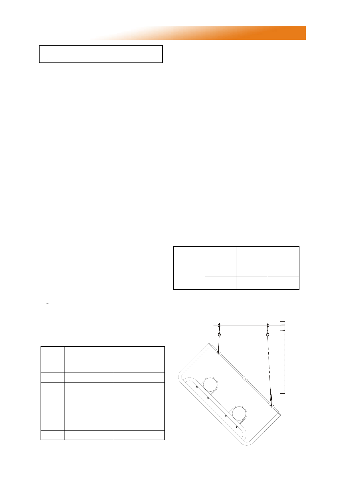
These radiant tube heaters can be wall mounted
using the appropriate bracket (AmbiRad part no
WMB-13-22-38).
When using the wall mounting brackets the
heater must be inclined at an angle between 30°
and 45°.
Burner MUST be mounted on the lower tube.
It must also be installed to the right hand side of
the heat exchanger.
Table 1 Angle Mounting
1.3 Heater Suspension
See fig 1b. Attachment to the heater
support lugs should be made by a ‘speed
link’, D shackle or in the case of drop rods, a
closed formed hook. The hanging attachments
to overhead steelwork etc. must be purpose
made to good sound engineering practice or of
a proprietary type fixing. They must be
adequately fixed and designed to carry the
Figure 1.a. Angle Mounting using the Wall
mounting bracket
Heater
Size
20 - 50
Required
angle
30-35°
45°
Chain
length
12 links 3
16 links 3
Eyebolt
position
.
Model Recommended Mounting Height (m)
20
25
30
35
40
45
50
Horizontal
4.5 - 7.0m 3.5 - 5.0m
5.0 - 8.0m 4.0 - 5.0m
5.5 - 9.0m 4.0 - 6.0m
6.0 - 10.0m 4.5 - 6.5m
6.5 - 11.0m
7.0 - 12.0m
7.5 - 13.0m
5.0 - 7.0m
5.5 - 8.0m
6.0 - 9.0m
Inclined / wall
mounted
E
4
Page 5
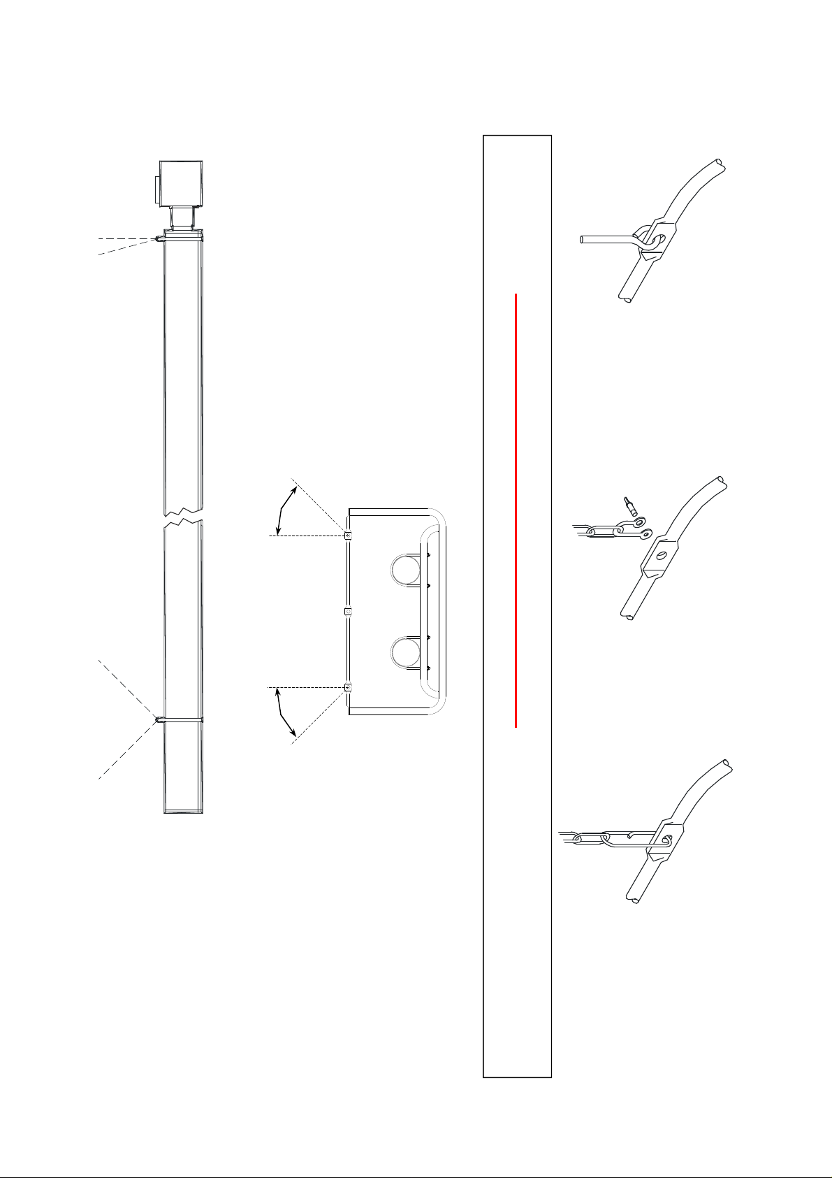
Figure 1.b. Recommended Methods of Heater Suspension.
of inclination is 15°.
Where supports are inclined,
maximum recommended angle
15° max.
Vertical suspension chain ideal.
*
more than 45°.
be equal and not
* These angles to
Drop rod with formed hook.
note. hook or eyebolt must
be closed tight.
Shackle method of
attachment. Pin must
be tightened by pliers.
*
.
Vertical or inclined
support is recommended
angle of inclination greater
Where chain supports have an
than 15° an equal and opposite
suspension on this
plane is acceptable.
5
THE HEATER SHOULD SLOPE DOWNWARDS TOWARDS THE RETURN BEND
BY APPROX. 10mm FOR BOTH HORIZONTAL AND WALL MOUNTED INSTALLATIONS.
Typical Speedlink attachment.
Page 6
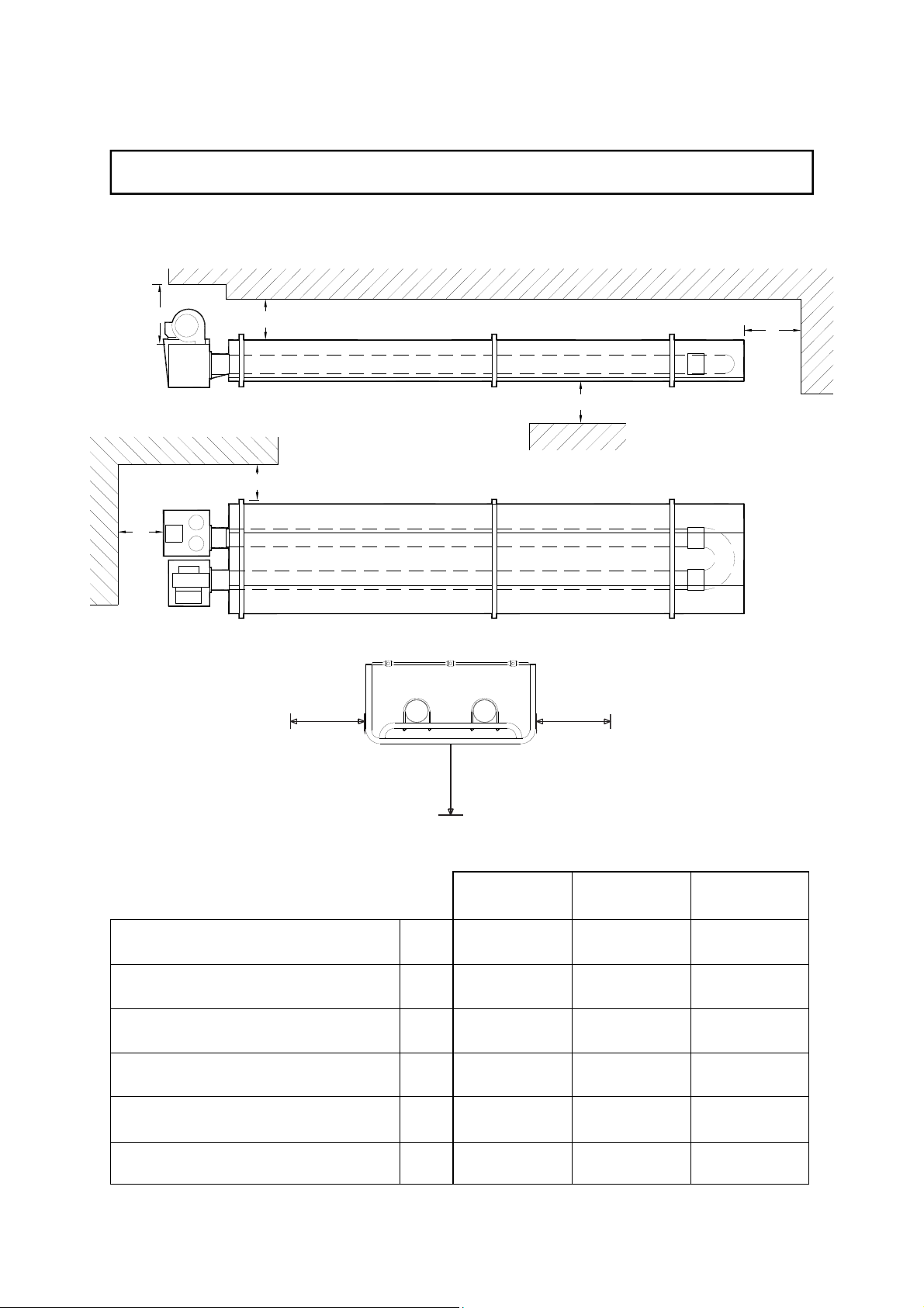
1.5 Clearance to Combustibles.
The minimum clearances to combustible materials are given in the tables below. These
minimum distances MUST be adhered to at all times.
Figure 2 Diagram illustrating the clearance to combustibles
B
E
A
D
C
F
C C
VSXUT
Above Reflector
Above Burner / Heater Outlet
To the Sides
Below Tubes
Horizontally from Heater Outlet
(UNFLUED)
End Wall
A
B
C
D
E
F
D
20/25/30 35/40 45/50
100 100 100
500 500 500
1300 1300 1300
2300 2500 2500
1200 1200 1200
700 700 700
6
Page 7
1.6 Gas Connection and Supply
Before installation, check that the local
distribution conditions, nature of gas
and pressure, and adjustment of the
appliance are compatible.
A competent or qualified engineer is required to
either install a new gas meter to the service
pipe or to check that the existing meter is
adequate to deal with the rate of gas supply
required. Installation pipes should be fitted in
accordance with BS 6896, so that the supply
pressure, as stated in Table 2 will be achieved.
It is the responsibility of the competent engineer
to ensure that other relevant Standards and
Codes of Practice are complied with in the
country of installation. Pipes of smaller size
than the heater inlet gas connection must not
be used. The complete installation must be
tested for soundness as described in the
country of installation.
The gas union service cock MUST be
fitted in the gas supply close to the
heater, but not onto the burner itself.
Take care when making a gas connection
to the heater not to apply excessive turning
force to the internal controls.
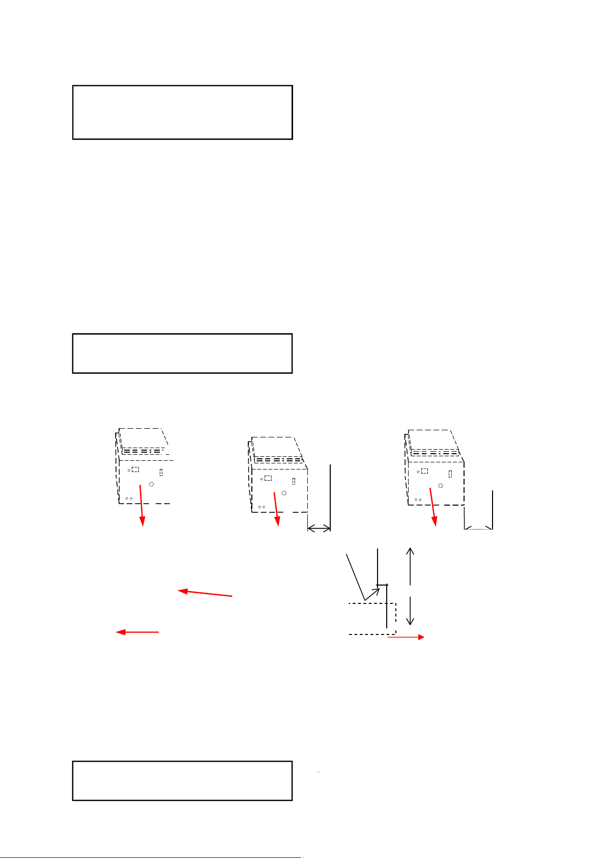
A flexible hose is installed to allow safe linear
expansion of the heater without creating undue
stress on the gas supply pipe work. It is
therefore important that a tested and certified
hose assembly made to ISO 10380, supplied
with ½” BSP female cone seat adapters, is
installed as per these instructions.
It is also important to ensure that expansion is
taken up in the body of the flexible hose, and
not on its attachment to the pipe work. Th e cone
seat adapter supplied on one end of the flexible
gas hose provides a `swivel` action, and must
be fitted on the burner using a ½” BSP barrel
nipple to provide ease of disconnection for
future servicing. This assumes that the heater
and fixed gas supply to the isolating valve have
been installed.
The installation layout described below is
the only method recommended by the
institute of gas engineers, the hose
manufacturer, and AmbiRad and must only be
carried out by a qualified/competent gas
engineer.
Figure 3. Correct Installation of Flexible Gas Connection
fig.a
Arrow denotes
direction of
expansion.
fig.d
Depending on the specific installation, the
flexible gas hose may be routed to the gas
cock at any of the following angles in relation to
the burner:
Vertical (fig.a)
45° angle (fig.b)
90° angle (fig.c)
Any other position in between these angles is
acceptable.
A clearance distance ‘x’ of min 200mm
must be observed to allow side door
access .
fig.b
x
50 +/- 20mm
Care must be taken to observe the minimum
pipe bend diameter (minimum 250mm,
maximum 350mm) & pipe expansion distance
(minimum 30mm, maximum 70mm) as shown in
fig.e.
Maximum bend diameter for the 1000mm
hose is 450mm.
The correct installation as shown will allow
for approx 100mm of movement due to
expansion.
7
Burne
fig.c
300 +/- 50mm
x
fig.e
Page 8
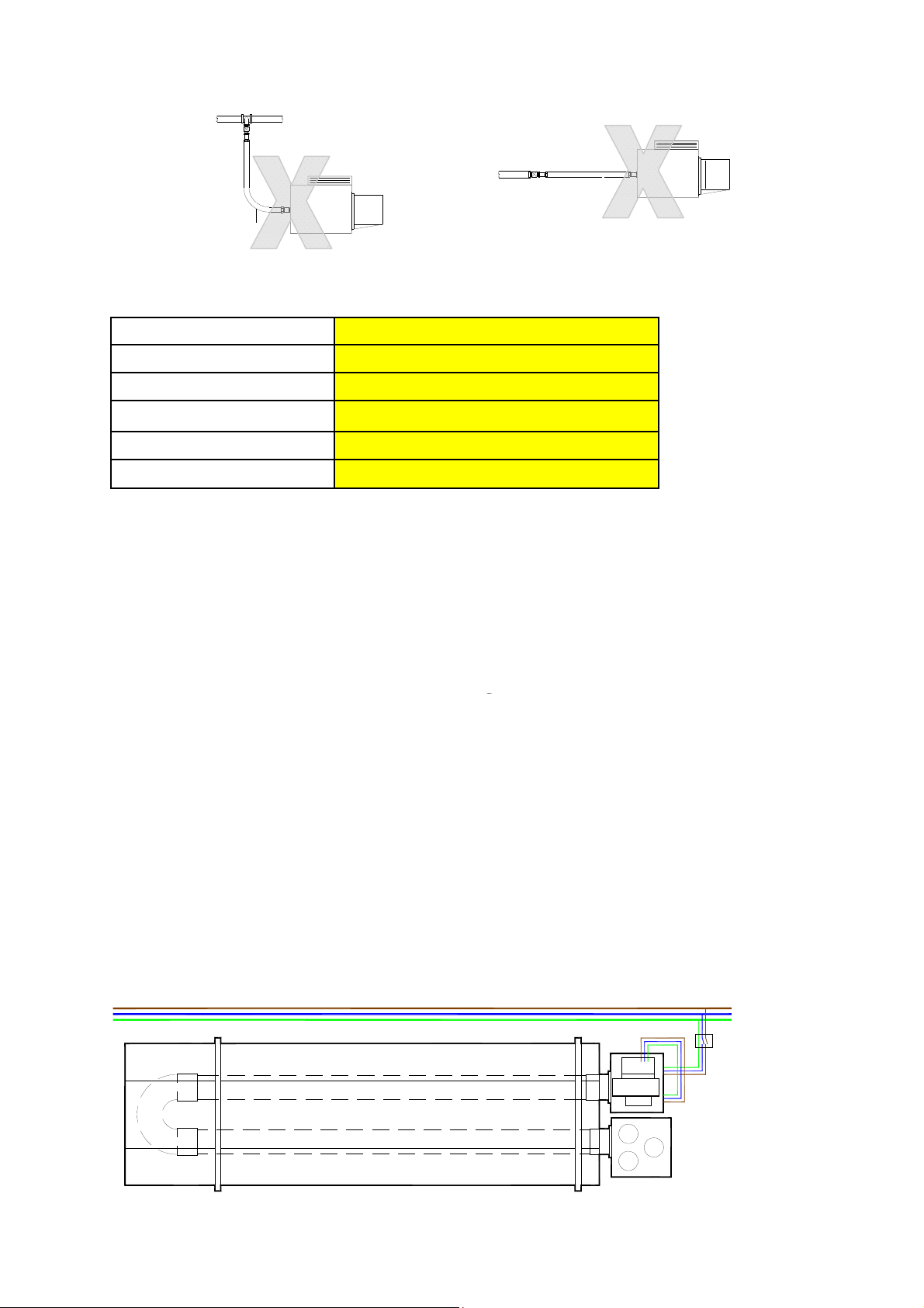
fig.f
fig.g
The methods shown in fig.f and fig.g are unacceptable, due to undue stress on the hose & fittings.
Table 2 Gas Supply Pressures
Gas Category I2H
Gas Type
Max Supply Pressure (mbar)
Min Supply Pressure (mbar)
Nominal Pressure (mbar)
Gas Supply
Connection R½ ½in BSP Internal Thread
1.7 Electrical Connection
This appliance must be earthed.
Supply 230V 50Hz single phase.
Standard heater 116W.
Current rating 0.55 amp max (inductive).
Fuse: external 3 amp.
All electrical work should be carried out to IEE
standards by a competent electrician. The
electrical connection to the heater is made by
Natural Gas (G20)
25
17
20
Green & Yellow Earth;
Blue Neutral;
Brown Live
It is recommended the heater or group of
heaters are controlled by thermostats, a time
switch and if required manual control switches
and a frost thermostat.
We recommend use of AmbiRad approved
controls. Please refer to control manual for
siting and installation details.
Where alternative manufactures controls are
used, please refer to their instructions for their
siting and installation details.
means of a three pin plug-in power connector.
Live, neutral and earth connections should be
made via a flexible supply cable to the power
connector and routed clear of the heater or
tubes.
The flexible supply cables should be of 0.5mm²
and comply with BS 6500. The wires in the
mains lead are coloured in accordance with the
following code:
Figure 4.b Typical Wiring Connections
Figure 4.a Single Phase Wiring
Fused Spur
Fan plugs into burner
8
Page 9
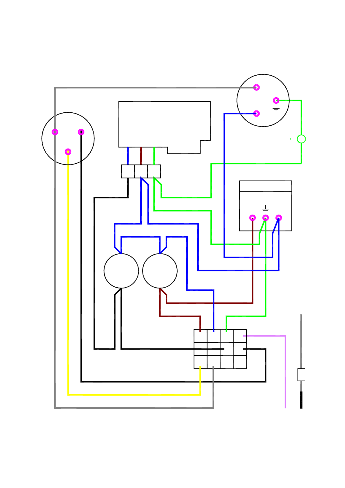
Figure 5. Internal Burner Wiring Diagram.
C.
N.C.
N.O.
VACUUM
SWITCH
VALVE
J.S.T.
BLUE
GREY
SOLENOID VALVE
2
1
BLUE
3
GRN/YLW
BLUE
N
GREEN/YELLOW
EMC FILTER
MAINS INPUT
BLUE
L
L
FAN
N
GREY
YELLOW
BLACK
WHITE
BURNER
ON
MAINS
LAMPS
WHITE
GREY
ON
BROWN
BROWN
MAIN J.S.T.
YELLOW
BLUE
BLUE
1
9
2
3
4
8
7
11
10 12
GRN/YEL
PINK
BLACK
FLAME SENSOR
IGNITER
9
Page 10

1.8 Ventilation Requirements
AmbiRad tube heaters can be operated as
flued or unflued appliances in accordance with
the relevant national requirements in the
country of installation.
1.8.1 Unflued Radiant Heater
Radiant tube heaters can be operated as
unflued appliances so that the concentration of
Carbon Dioxide (CO
will be inhaled does not exceed 0.28%. BS EN
13410 is a guide to achieving this requirement.
If the building air change rate exceeds 1.5 per
hour or if the heat input is less than 5W/m³, no
additional ventilation is required.
In addition to the ventilation requirements,
consideration needs to be given to the
possibility of condensation forming on cold
surfaces.
It should be noted that the clearance distance
around the burner increases when the unit is
operated unflued (see section 1.5). It should be
ensured that the combustion gases do not
impinge on any combustible materials.
Mechanical Ventilation
Mechanical ventilation must be rated at
minimum 10m³/h per kW input using
appropriately sized fans and interlocked with
heaters.
Natural Ventilation
BS EN 13410 should be used to size air vents
to provide adequate ventilation, an example of
this calculation is given below:
Site Details:
20°c Internal Operating Temperature
0°c Outside Air Temperature
5m between high and low level vents
Following the sizing procedure in BS EN 13410
gives an air exit velocity of 1.6m/s. This
equates to a free area vent at both high level
and low level of 17.36cm²/kW free area.
1.8.2 Flued Radiant Heater
In buildings having an air change rate of less
than 0.5 per hour, additional mechanical or
natural ventilation is required. For detailed
information, please see BS6896 section
5.2.2.2.1
Mechanical Ventilation
Mechanical ventilation must be installed to
) at positions where the air
2
meet a minimum of 0.5 air changes per hour
using appropriately sized fans and interlocked
with the heaters.
Natural Ventilation
Low level ventilation openings with a free area
of at least 2cm²/kW shall be provided. See
section 5.2.2.2.2.1.
1.9 Flue and Combustion Air Inlet
- Options
Dependent on the type of burner fitted to your
heater it is possible to have configurations of
flue and combustion air inlet options to those
shown overleaf:
1.9.1 Important Information
1.9.1.1 Option 1 and 2
A suitable flue system complying with EN1856-1
(type T250 N1 D Vm L11040 O50) should be
used. Flue size 125mm diameter twin wall.
Flue systems can run either vertically or
horizontally up to a maximum length of 9.5m
(including up to 2 x 90° bends plus the terminal).
The minimum flue length shall be 1m.
The flue system must be terminated in a
vertical position and in accordance with the
British Standard Code of Practice BS 5440: Part
1 - Installation and maintenance of flues and
ventilation for gas appliances of rated input not
exceeding 70kW net (1st, 2nd and 3rd family
gases), and the flue system manufacturers
instructions as supplied with the flue.
1.9.1.2 Option 3
A suitable flue system complying with EN1865-1
(type T200 P1 W V2 L50050 O00) should be
used. Flue size 100mm diameter single wall.
The maximum flue length shall be 9.0m
(including up to 2 x 90° bends plus the terminal).
The minimum flue length shall be 1m.
• Option 1
For flued products of combustion and no
ducted air please refer to Figure 6.a.
• Option 2
For ducted air and products of combustion to
ventilated area please refer to Figure 6.b.
• Option 3
For flued products of combustion and ducted
air via concentric pipe please refer to Figure
6.c.
10
Page 11

The flue system must be terminated vertically
only and in accordance with the British
Standard Code of Practice BS 5440: Part 1 Installation and maintenance of flues and
ventilation for gas appliances of rated input not
exceeding 70kW net (1st, 2nd and 3rd family
gases), and the flue system manufacturers
instructions as supplied with the flue.
1.9.2 Installation
Connection to an appliance which is not
connected to the fuel supply may be carried out
by a competent person. However, connection to
an appliance that is connected to the fuel supply
be carried out by a registered installer.
must
If the flue passes through a wall, ceiling, or roof
made from combustible material then it has to
be sleeved so as to provide a minimum of a
50mm void between the exterior of the flue and
the internal wall of the sleeve. A minimum of
50mm must be maintained as a clearance
distance to all other combustible materials.
The manifold should be supported by chain,
stainless steel flexible wire, or other flexible
means from the roof structure to allow
movement caused by thermal expansion.
The maximum distance between supports is
1.5m for horizontal runs.
Wall bands are not load bearing and give lateral
support only. If used, wall bands should be fitted
every 3m on vertical runs to ensure the system
is rigidly held. The system should be braced
immediately below passing through the roof line
to ensure the flashing does not suffer lateral
pressures.
The maximum height unsupported above the
roof line is 1.5m. Where a joint is above the
roofline it should be determined that in extreme
wind conditions this joint would not be over
exerted. If there is any doubt then a guy wire
should be used. Beyond this guy wires should
be installed every meter.
The POCED is capable of withstanding its own
weight when installed in accordance with these
instructions and the Regulations shown below.
The exhaust flue should be adequately
supported from the building structure and
installed in accordance with the British
Standard Code of Practice BS 5440: Part 1 –
Installation and maintenance of flues and
ventilation for gas appliances of rated input not
exceeding 70kW net (1st, 2nd and 3rd family
gases), and the flue system manufacturers
instructions as supplied with the flue.
See reference BS 6896. Condensate drain
pipes must be protected against the effects of
freezing.
1.9.3 Condensation
When designing the flue system the prevention
of the formation and entrapment of
condensation must be a key consideration.
Horizontal flue should be fitted ensuring a slight
gradient approx 5
Where condensation is unavoidable traps
should be included to encourage the
condensates to flow freely to a point from which
they may be released, preferably into a gully.
The condensate pipe from the flue to the
disposal point must be made from corrosion
resistant pipe of not less than 25mm internal
diameter.
1.9.4 Method of Jointing Tube
1.9.4.1 Option 1
All pipe lengths and flue gas carrying
components are joined together by a twist lock,
bayonet system. The system should be installed
with the visible male collar pointing upwards,
this is reaffirmed by the directional arrow
pointing upwards, indicating the directional flow
of flue gases. Taping of the joints is
unnecessary.
1.9.4.2 Option 3
The components are joined by pushing the male
spigot and female socket together until the stop
is reached. No sealant is required, but can be
applied if the formation of condensation is
anticipated.
To seal use an applicator gun and apply a 4mm
diameter bead of high temperature silicon
jointing compound externally round the end of
the male spigot and internally round the end of
the female socket.
Push the male spigot into the female socket
using a slight rotating movement to spread the
jointing compound uniformly until both fittings
have fully engaged.
Note The silicon jointing compound remains
workable after application for only 5 minutes
°
towards the terminal.
11
Page 12
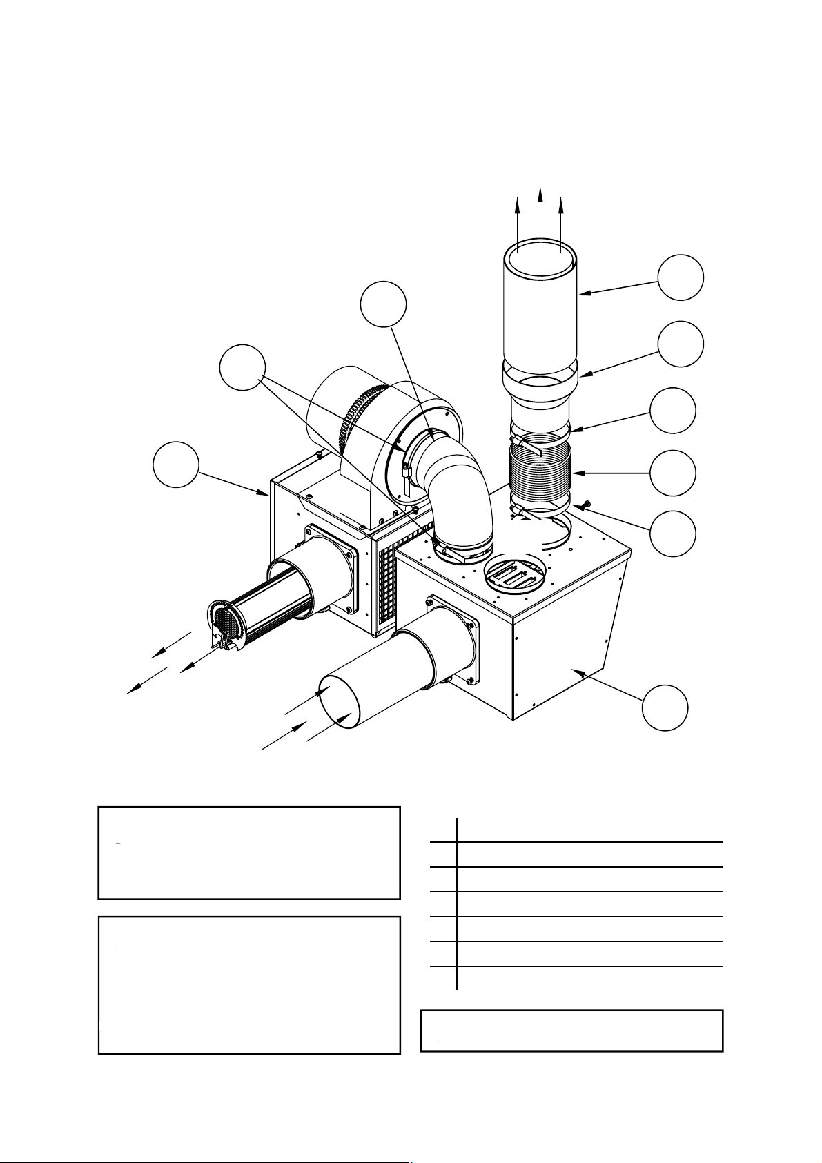
Option 1 - Figure 6.a. Forced Burner with Heat Exchanger (Standard Flue)
For flued products of combustion and no ducted air
Products of combustion
J
G
L
K
G
E
Firing
tube
Products of combustion
Maximum flue length = 9.5m @ Ø125mm
Maximum no of bends = 2
All flues must terminate vertically.
For further information on flue runs, please refer
to section 1.9.1 BS 5440 pt.1
Air
Inlet
E Forced Burner
F Heat Exchanger
G 100mm (4ins) Clips x2
H 100mm (4ins) Flexible Flue
H
G
F
Ducted air must be used in locations
where there is airborne dust or where
there is a polluted atmosphere e.g. Chlorinated
Vapours.
Maximum length = 9m
Minimum diameter = 100mm
Maximum no of bends = 2
J 100mm (4ins) Flexible Flue to Fan
K 127mm (5ins) to 100mm (4ins) Reducer
L 127mm (5ins) Twin Wall Flue Pipe
Ventilation requirements are as detailed in
section 1.8
12
Page 13
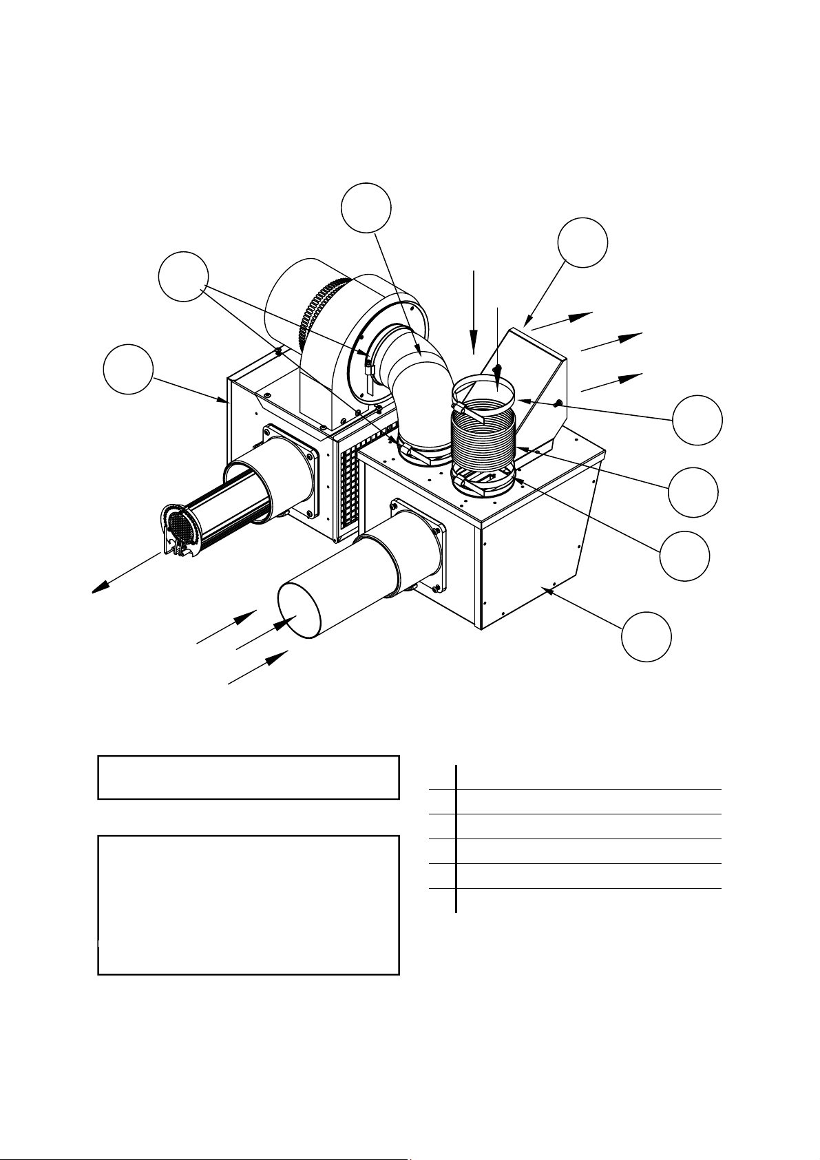
Option 2 - Figure 6.b. Forced Burner with Heat Exchanger (No External Flue)
For ducted air and products of combustion to ventilated area
J
E
Firing
tube
G
Fresh
Air
M
Products of
combustion to
ventilated area
G
H
G
Products of
combustion
Ventilation requirements are as detailed in
section 1.8
Ducted air must be used in locations
where there is airborne dust or where
there is a polluted atmosphere e.g. Chlorinated
Vapours.
Maximum length = 9m
Minimum diameter = 100mm
Maximum no of bends = 2
F
E Forced Burner
F Heat Exchanger
G 100mm (4ins) Clips x2
H 100mm (4ins) Flexible Flue
J 100mm (4ins) Flexible Flue to Fan
M Shroud for unflued heater installation
13
Page 14
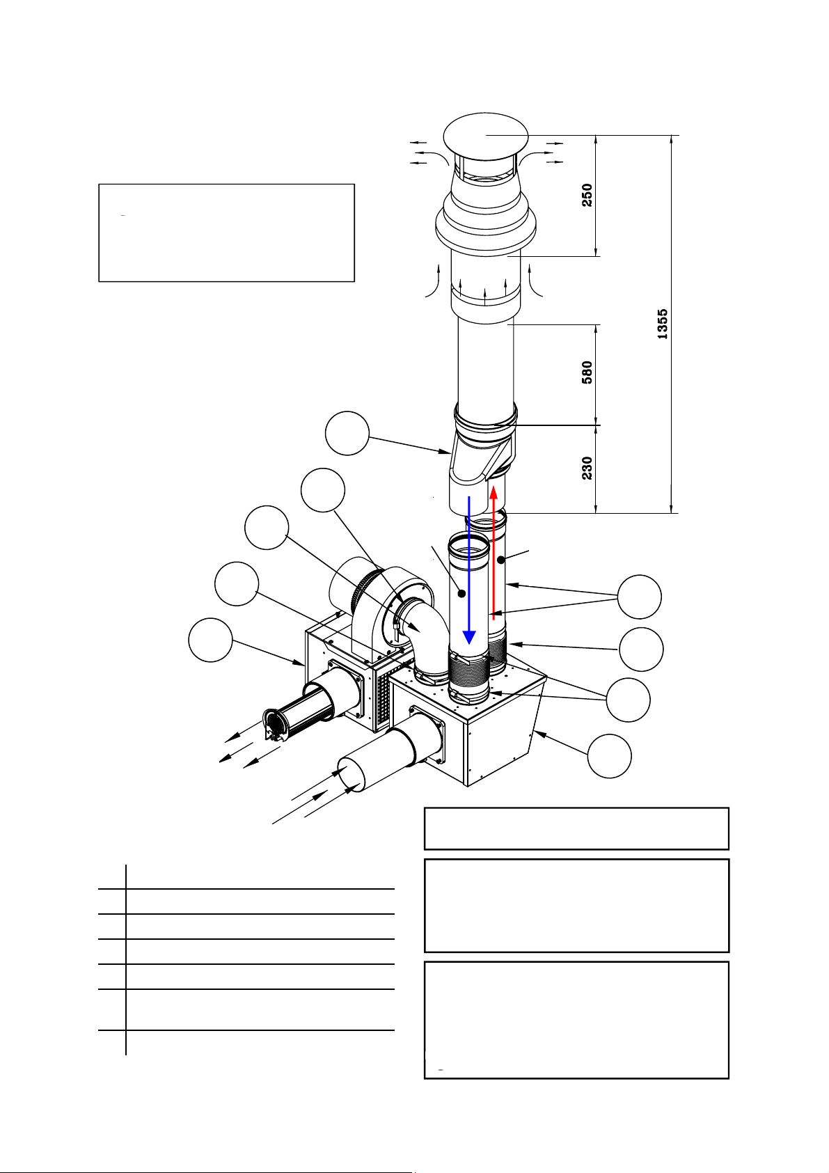
Option 3 - Figure 6.c. Forced Burner with Heat Exchanger (with Concentric Flue)
For flued products of combustion and
ducted air via concentric pipe.
IMPORTANT NOTE
This option is a type B
with ducted air and is not a room sealed
balanced flue product.
flue system
23
Products of
combustion
Fresh
Air
Inlet
P
G
J
G
E
Firing
Tube
Products of
combustion
E Forced Burner
F Heat Exchanger
G 100mm (4ins) Clips x2
H 100mm (4ins) Flexible Flue
J 100mm (4ins) Flexible Flue to Fan
N Flue Extension optional
(0.25m/0.5m/1.0m)
P Concentric Flue Terminal
Fresh
Air
Products of
combustion
N
H
G
F
Ventilation requirements are as detailed in
section 1.8
Maximum flue length = 9.0m @ Ø125mm
Maximum no of bends = 2
All flues must terminate vertically.
For further information on flue runs, please refer
to section 1.9.1 BS 5440 pt.1
Ducted air must be used in locations
where there is airborne dust or where
there is a polluted atmosphere e.g. Chlorinated
Vapours.
Maximum length = 9m
Minimum diameter = 100mm
Maximum no of bends = 2
14
Page 15
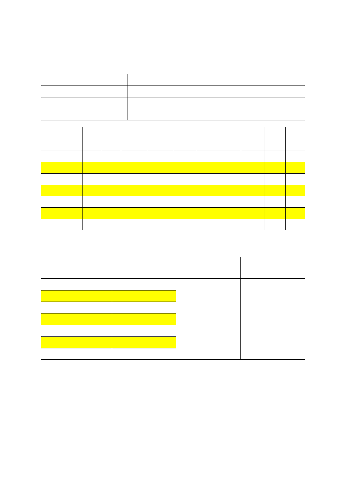
1.10 Table 3. Technical Details.
All heaters to run on Natural Gas (G20)
No of Injectors
Gas Connection
Flue Nominal Bore mm (in)
Unitary Fan Motor Details
Heater
Model
VSX20UT
VSX25UT
VSX30UT
VSX35UT
VSX40UT
VSX45UT
VSX50UT
Heat Input kW Gas
Gross Nett
1
½ in BSP Internal thread
125 (5)
230 volt 1 phase 50Hz
Injector
Flowrate
(m³/hr)
20.0 18.0 1.9 10.0 1.7 450x4047x746 114 0.5 2501
25.0 22.5 2.4 9.4 1.9 450x4047x746 114 1.0 2507
32.0 28.8 3.1 13.0 2.0 450x4047x746 114 1.0 2507
36.0 32.4 3.4 12.3 2.3 450x5927x746 158 1.0 2507
40.0 36.0 3.8 12.8 2.4 450x5927x746 158 0.5 2560
44.0 39.6 4.2 11.6 2.9 450x5927x746 158 0.5 2560
49.5 44.6 4.7 12.8 2.5L 450x7692x746 205 0.5 2560
Pressure
(mbar)
Injector
Size
(mm)
Size
(h x l x w)
Weight
(Kg)
Fan
Rating
(A)
Fan
Type
Table 4. Flue details
Heater Model
VSX20UT
VSX25UT
VSX30UT
VSX35UT
VSX40UT
VSX45UT
VSX50UT
Mass Flow Rate of Flue
Gasses (kg/s)
0.0116
0.0132
0.0133
0.0166
0.0173
0.0196
0.0220
Flue Pressure (Pa)
Maximum Flue
Resistance
35 - 42 190 - 250
Flue Gas Temp (°C)
15
Page 16
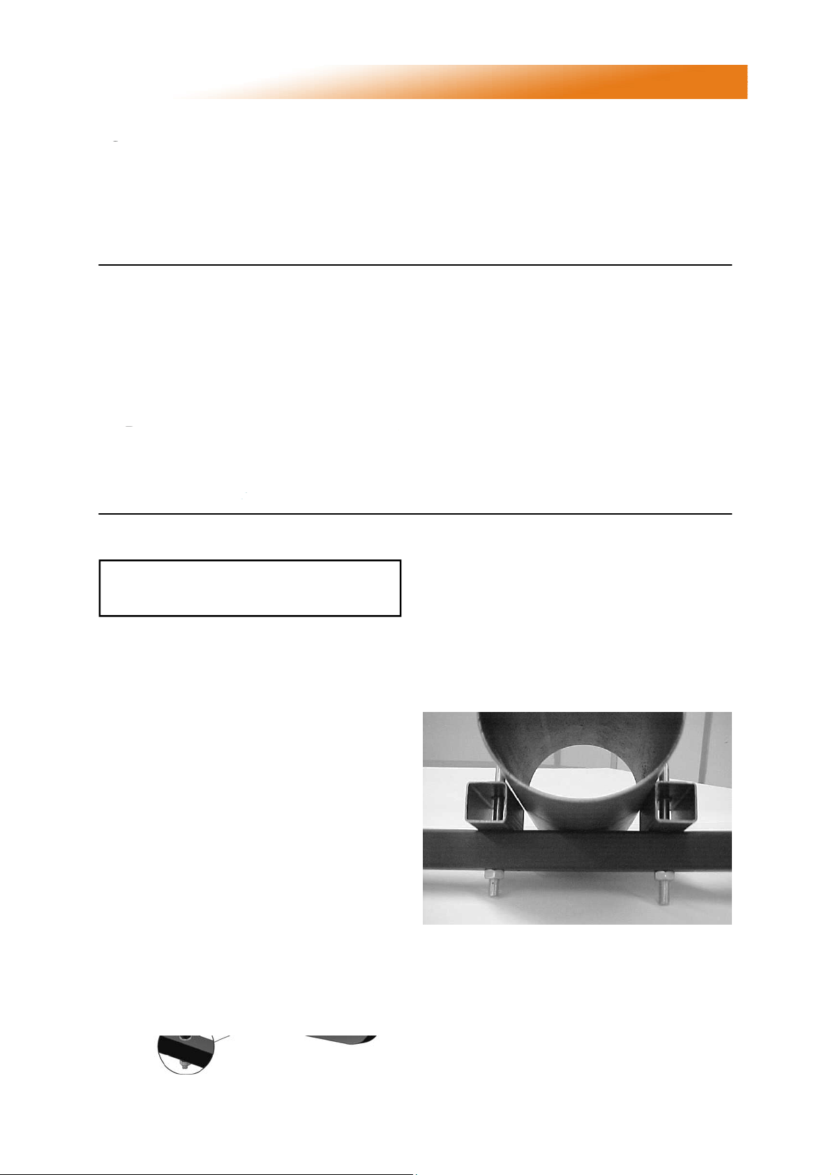
2. Assembly Instructions.
PLEASE READ this section prior to
assembly to familiarise yourself with the
components and tools you require at the
various stages of assembly. Carefully open the
packaging and check the contents against the
parts and check list.
The manufacturer reserves the right to alter
specifications without prior notice.
2.1 Tools Required.
The following tools and equipment are advisable
to complete the tasks laid out in this manual.
Trestles
4 & 5mm
Allen keys
Leather
Faced
Gloves
Please ensure that all packaging is
disposed of in a safe environmentally
friendly way.
For your own safety we recommend the
use of safety boots and leather faced
gloves when handling sharp or heavy items. The
use of protective eye wear is also
recommended.
Suitable alternative tools may be used.
Pozidrive
Screwdriver
Tape
Measure
Spanner
Set
2.2 Assembly Notes.
Please read these assembly notes in
conjunction with the correct assembly
drawings (figs 7 to 10).
2.2.1 Turbulators
Ensure the correct length and quantity are
inserted into their respective correctly
identified tube(s) as detailed in the assembly
drawings.
2.2.2 Brackets
Tighten clamping ‘U’ bolt arrangement to
tubes ONLY WHERE STATED on the
assembly drawings.
2.2.3 Tube alignment sections
For VSX50 Angle Mounted Installations
ONLY. To allow for differential expansion of
the tubes, a tube alignment assembly is fitted to
the first bracket on the fan side radiant tube.
Position U bolt tube alignment sections over the
tube and through bracket prior to clamping.
2.2.4 Reflectors.
All reflectors AND canopies must be
positioned/attached to the brackets exactly
as detailed in the assembly drawings.
Remove the protective plastic coating.
16
Page 17
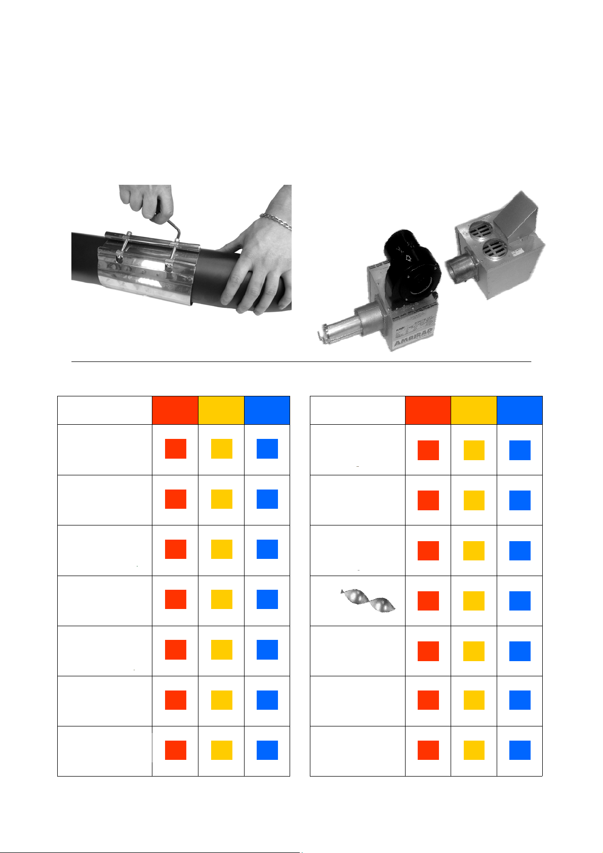
2.2.5 Couplers.
Locate and position tube couplers at the end
of the tubes. Ensure socket heads are
facing outwards & the pre-fitted bolts in the
couplers line up with the locating holes in the
tubes.
Ensuring the bolts are not over tightened.
2.2.6 Burner and Heat Exchanger Assembly.
Slide the burner assembly onto the RIGHT
HAND TUBE when viewed from above, ensuring
it is fully engaged.
Slide heat exchanger onto the LEFT HAND
TUBE when viewed from above, ensuring it is
fully engaged. The hose connections should face
vertically.
Secure both assemblies with grub
screws.
2.3 Identification check list
COLOUR CODE
Burner
Heat
Exchanger
U Bend
Inner
Reflectors
Outer
Canopy
VSX
20/25/30
1x
1x
1x 1x
2x 3x
2x 3x
VSX
35/40/45
1x
1x
VSX
50
1x
1x
1x
4x
4x
COLOUR CODE
Inner End
Caps
Outer
Canopy
End Caps
Tubes
Turbulators
Couplers
VSX
20/25/30
2x 2x
2x
2x
2x
2x
VSX
35/40/45
2x
2x
3x
2x
VSX
50
2x
2x
4x
3x
4x
Brackets
No.5
Torque
Screw
3x 4x
5x
13x 14x 15x
M8 U Bolt
M8
Full Nut
17
8x 6x
10x
16x 22x 28x
Page 18

COLOUR CODE
M6
Mudwasher
M6
Washer
M6
Full Nut
M6 x 35
Setpin
VSX
20/25/30
12x
4x
6x
4x
VSX
35/40/45
16x
6x
10x
6x
VSX
50
20x
8x
14x
8x
COLOUR CODE
M4 x 10
Pozi Setpin
M4
Full Nut
M4
Washer
M6 x 15
Setpin
VSX
20/25/30
7x
1x 2x
7x
2x
VSX
35/40/45
8x
8x
4x
2.4 Prior to assembly
• Ensure the area in which you are working is safe and clear of obstructions.
• Identify with the components in the check list and in which order they will be assembled.
• Arrange the trestles* in a straight line to allow for length of tubes.
• Remove all protective plastic from underside of Stainless Steel Reflectors / inside of End Caps.
* if saw horses cannot be located, ensure any alternative is sound and can carry the heater weight.
Methodology: To cater for the expansion of the firing leg, all U bolts on the firing leg (except the one
closest to U bend) are to be loose as described below. All reflectors, tubes, brackets and canopies
are bolted together.
VSX
50
9x
3x
9x
6x
2.5 Step by step installation.
2.5.1 Tubes and Turbulators
1
Locate and position tubes on trestles. After
deciding which end will have the burner, mark out the
position of the first bracket as shown in the assembly
drawings section. Slide brackets over tubes as
shown.
2x 2x 2x
2
VSX50 only: Locate & position the two shorter
tubes and affix to tubes using couplers. Keeping
the tubes in line, tighten the couplers evenly until
the tubes cannot be turned in the couplers.
0x 0x 2x
0x 0x 2x
18
Page 19
3
Locate and insert turbulator(s) into tube(s)
ensuring the correct length and quantity are inserted
into the correct tube. See assembly drawings section
for location & length.
2x 3x 3x
CAUTION — SHARP EDGES!
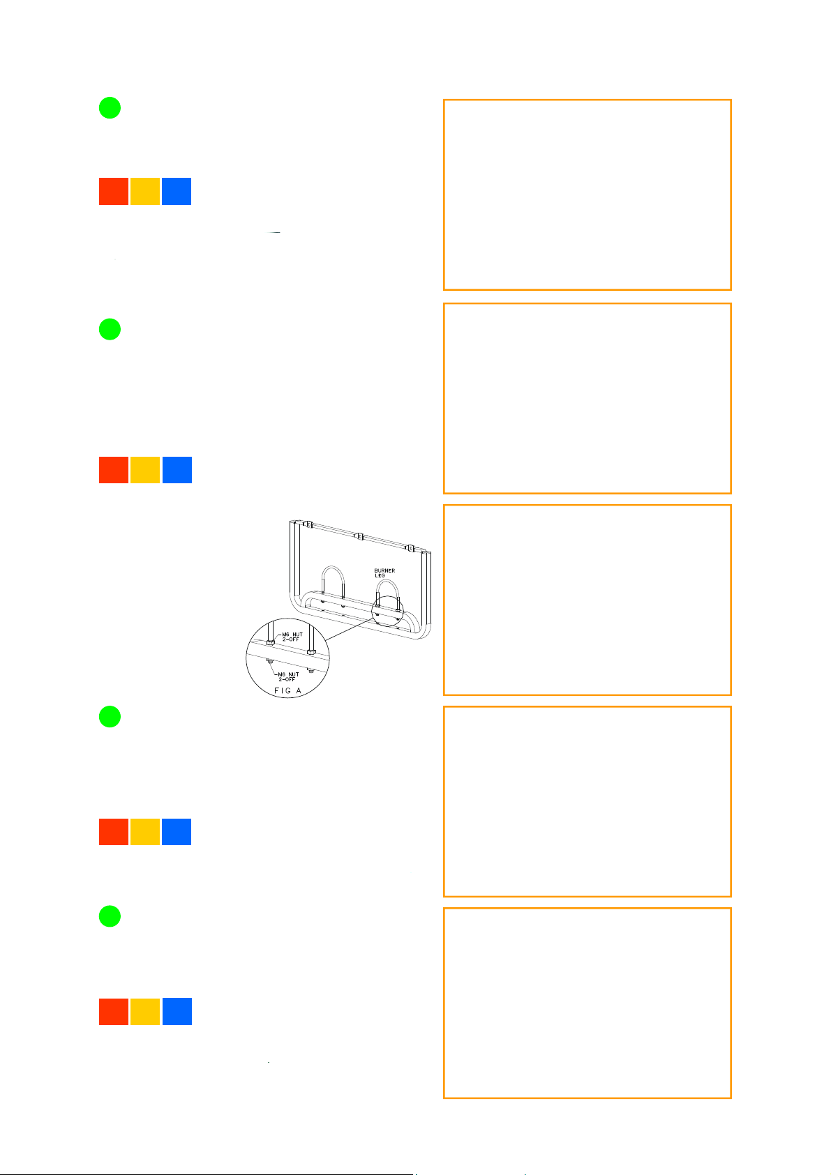
2.5.2 Brackets, U Bolts and U bend.
Fit the M8 U bolts over the tubes into the holes
4
in the bracket & loosely secure with M8 nuts &
washers, noting that all the brackets on the firing
tube (right hand) except the bracket adjacent to the
U bend should have nuts & washers on both sides
of the bracket to allow bracket to be tightened whilst
still allowing a 3mm gap for expansion between the
tube & U bolt. Refer to sketch below..
3x 4x
this stage.
Working at the opposite ends of the tubes to
the burner, locate & position two couplers so that
the socket heads are facing outwards & the
pre-fitted bolts in the couplers line up with the
locating holes in the tubes. Do not fully tighten at
this stage.
2x 2x 5 2x
5x
DO NOT tighten
any of the nuts at
L/H tube
R/H tube
6
Slide U bend into the open end of the couplers
ensuring the pre-fitted bolts engage in the pre-cut
holes in the U tube section. Tighten all four
clamping bolts to provide a tight grip between
tubes & U tube section.
1x 1x
1x
19
Page 20

2.5.3 Reflectors.
Remove protective film before starting.
Reflectors are supplied pre-punched and
are universal throughout the VSX series.
7
Starting at the burner end, slide the reflectors
through the brackets until they are all roughly in
position along the heater, referring to the assembly
diagram showing overlaps. Measure the distance
between the end of the burner end tubes & the
centre of the end bracket, This should be
6” (150mm), slide bracket along tubes to adjust,
then tighten U bolts on the end bracket.
2x 3x
3x
CAUTION — SHARP EDGES!
8
Slide end reflector so that the innermost
slotted holes line up with 1st bracket fixing holes,
then fix in place using M6 x 35mm pins, washers
& nuts.
2x 2x
9
slotted hole in 1st reflector, & bolt together using
M6 x 35mm pins, washers & nuts. Bolt 1st & 2nd
reflectors together using end elongated holes in
each. Refer to notes ‘W’, ‘X’, ‘Y’ and Z in fig.12 for
further details.
2x
Slide 2nd bracket to line up with innermost
4x 4x 4x
10
Repeat this procedure referring to the
assembly diagram for quantities used on specific
models, but noting that the final bracket is not
bolted to the reflector. (See photo)
At this stage all the U bolts should be
fully tightened.
20
Page 21

Locate M4 pins, washers & nuts into holes in
11
overlapping reflectors as shown.
1x 2x
1x 2x
1x 2x
3x
3x
3x
2.5.4 End Caps
12
Using M4 setpins & washers fix the blank end
cap beneath the reflector profile at the U bend end
with the flanges facing outwards.
3x 3x
3x 3x
2x 2x
13
end cap beneath the reflector profile at the burner
end with the flanges facing outwards.
3x
3x
2x
Using M4 setpins & washers fix the 'cut out'
3x 3x
3x 3x
3x
3x
2.5.5 Canopies
14
Remove protective film before starting.
Slide the outer canopies over the reflectors from
the U bend end ensuring correct location in reflector profile. Line up burner end canopy flush
with burner end reflector. Overlap canopies as
shown in the assembly diagram.
2x 3x
4x
CAUTION — SHARP EDGES!
15
Adjust canopies so that the holes on top align
with each other as detailed in the assembly
instructions. Locate and fix one No.5 torque screw
on every canopy overlap.
1x 2x
3x
21
Page 22

2.5.6 Canopy End Caps
16
Locate 6 off No.5 torque screws. Position the
blank canopy end cap with the end cap flanges
facing inwards, beneath the canopy profile at the
U bend end & fix with screws. Repeat procedure
for 'cut-out' canopy end cap, again ensuring the
flange faces inwards.
2x 2x
12x 12x
2x
12x
CAUTION — SHARP EDGES!
2.5.7 General
17
The heater assembly is now complete and can now be installed. We would recommend that the
burner and heat exchanger be assembled once the heater has bee n installed in the roof space.
1x 1x
1x
1x 1x
1x
2.6 Detailed Assembly Drawings
The following pages show the technical
dimensional details of the VSX heaters.
Please note the heater type, length and
22
reference number from the delivery/advice note
before identifying the correct model drawing.
Refer to figure 12 for details of ‘W’, ‘X’, ‘Y’ and
‘Z’ fastening and locations.
Page 23
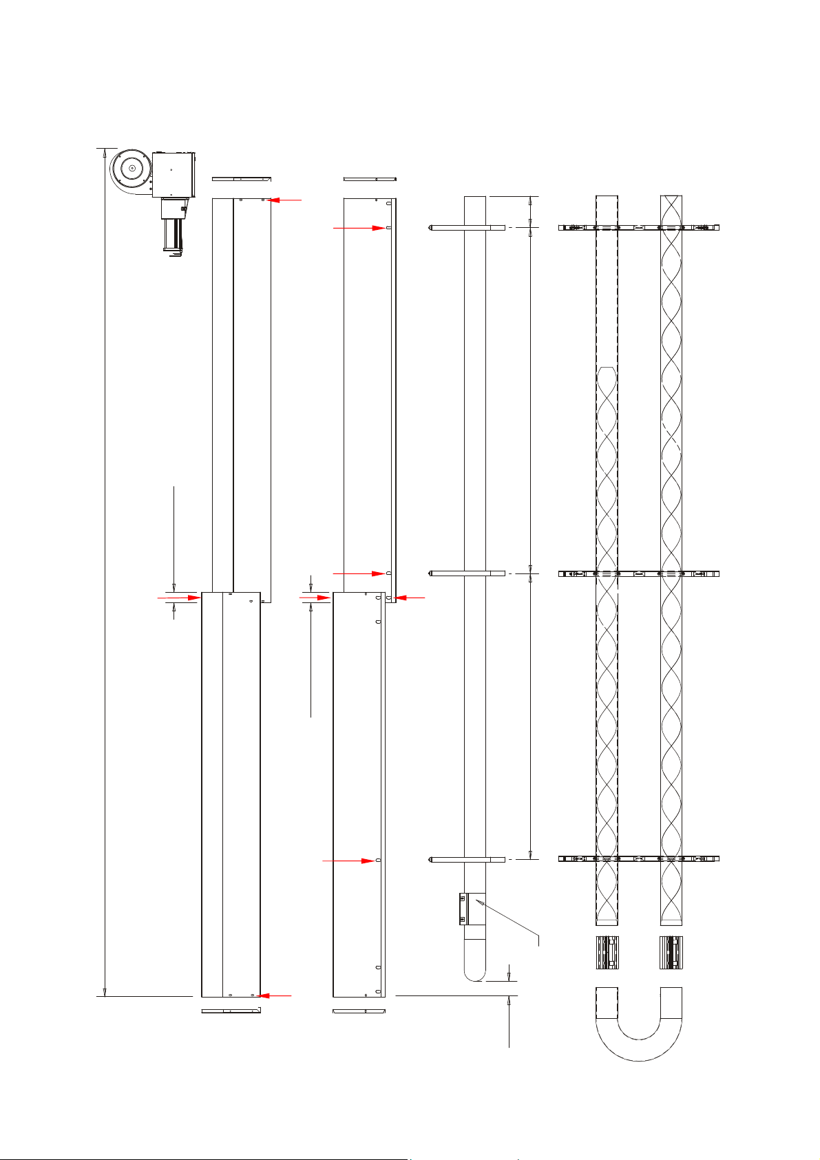
Figure 7. VSX 20/25/30
Y
150
Z
3400mm TUBE
4047mm REFERENCE
Y
50mm O/LAP
W
Z
X
50 mm O/LAP
1365mm 1650mm
976mm TURBULATOR
2600mm(20); 3400mm(25/30) TURBULATOR
Z
Y
COUPLER
38mm
23
Page 24
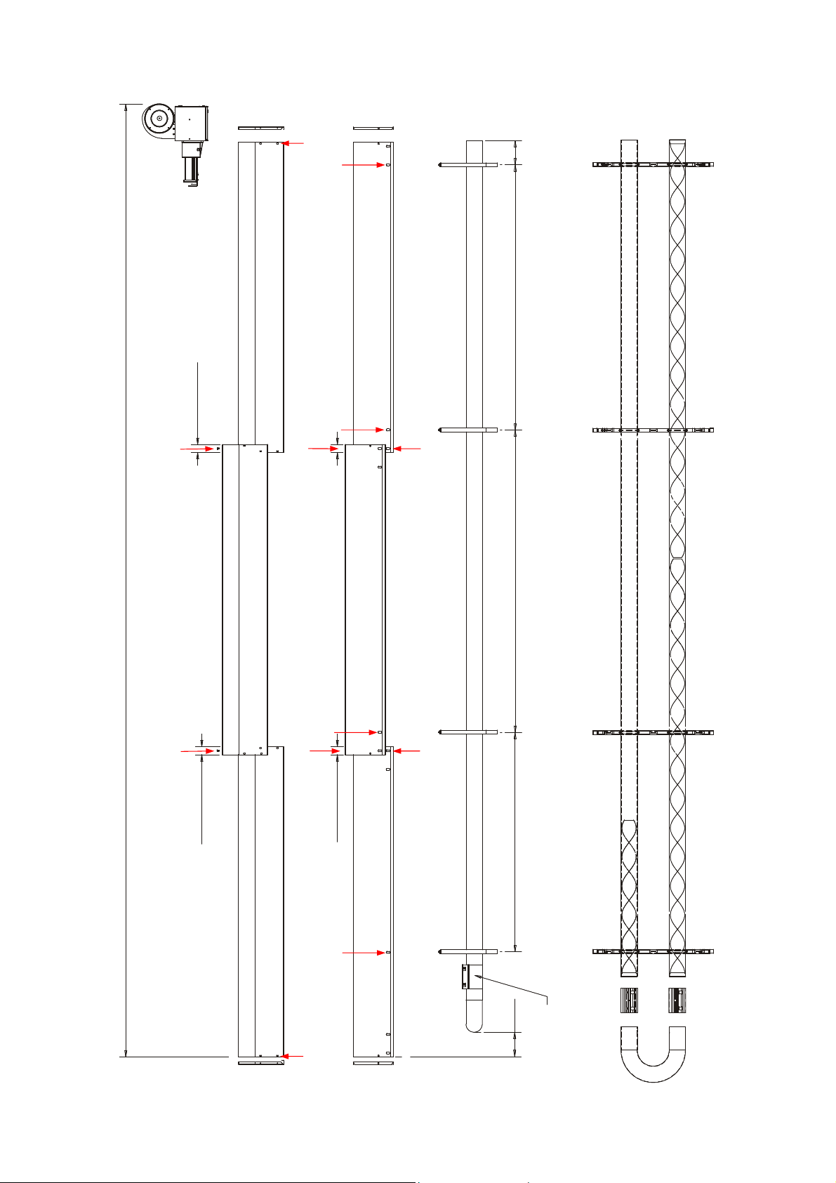
Figure 8. VSX 35/40/45
Y
Z
150
2600mm TURBULATOR
5200mm TUBE
5927mm REFERENCE
Y
Y
W
Z
X
50mm O/LAP
1880mm 1650mm
50mm O/LAP
Z
W
X
50mm O/LAP
50mm O/LAP
1365mm
976mm TURBULATOR
2600mm TURBULATOR
Z
138mm
Y
24
COUPLER
Page 25
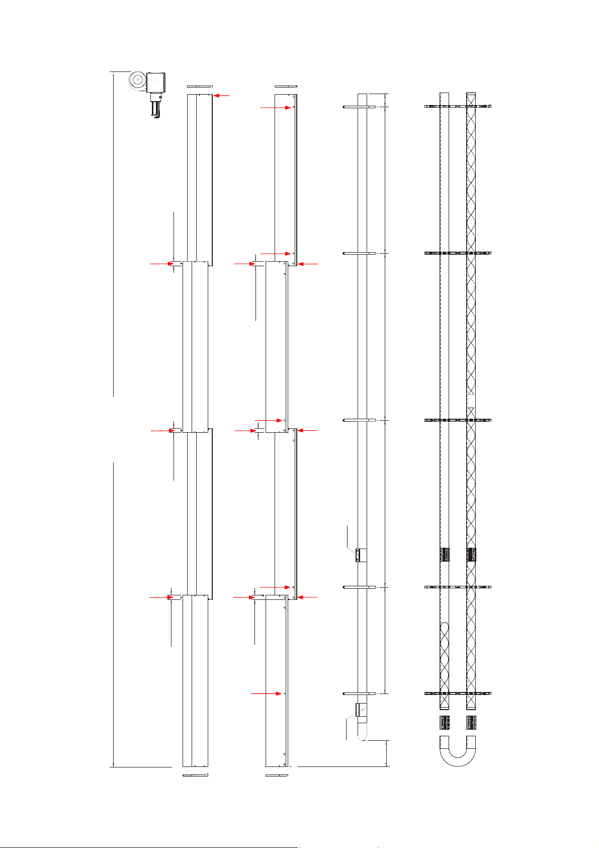
Figure 9. VSX 50
Y
Y
Z
50mm O/LAP
W
Z
X
50mm O/LAP
150
3400mm TURBULATOR
5200mm TUBE
7590mm REFERENCE
Y
Y
Z
W
50mm O/LAP
50mm O/LAP
X
1880mm 1880mm 1650mm
COUPLER
Z
W
50mm O/LAP
50mm O/LAP
X
1740mm TUBE
1200mm
976mm TURBULATOR
3400mm TURBULATOR
Z
25
COUPLER
293mm
Page 26
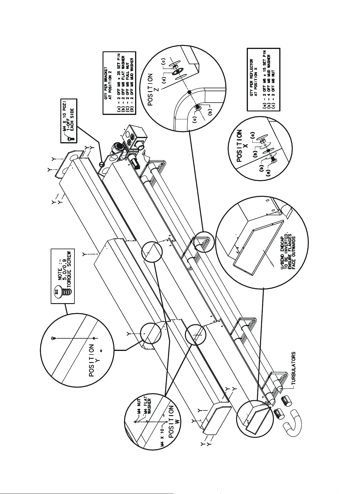
Figure 10. VSX Heater Breakdown (3 module shown)
26
Page 27
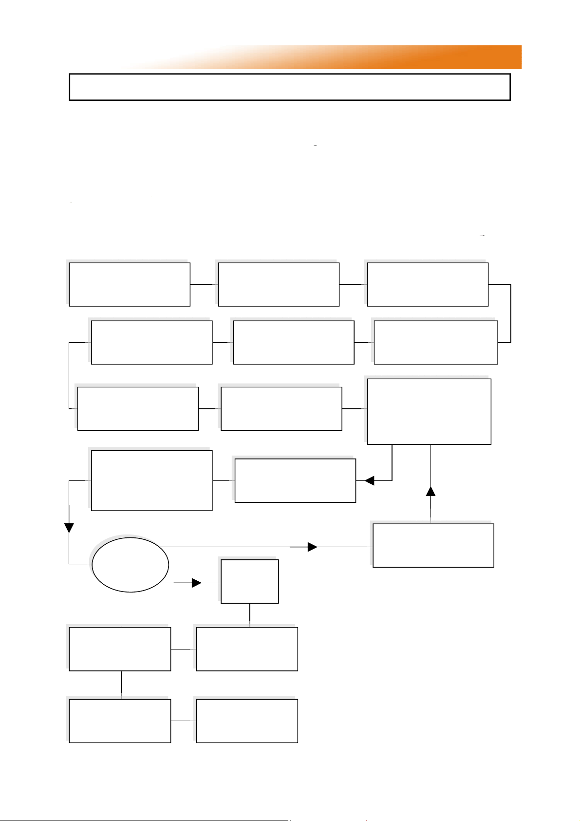
3. Commissioning Instructions.
These appliances should be commissioned by a qualified engineer.
3.1 Tools Required.
The following tools and equipment are advisable
Leather
Faced
Gloves
12mm
Spanner
Check installation has
been carried out to these
instructions.
Reconnect gas hose.
Open isolating valve.
Check soundness.
Open control housing and
check that all components
are securely fastened.
Pozidrive
Screwdriver
4mm
Allen
Key
Ensure gas and electricity
supplies are isolated.
Replace burner on tube
and secure.
Check thermostat is set to
maximum and is calling
for heat.
to complete the tasks laid out in this manual.
Suitable alternative tools may be used.
Small Flat
Head
Screwdriver
Manometer
Wrench with
Extension
Large Adjustable
Spanners or 22, 26 &
27mm Spanners for
fitting of Gas Flex.
Disconnect gas hose from
burner
Remove burner from tube
and inspect burner head.
(See servicing instructions)
Switch on electrical supply.
The red neon should now
be illuminated. If restarting
heater a delay of 15s
should be allowed.
13mm
Socket
A successful ignition is
indicated by the amber
light illuminating and
remaining illuminated.
Has the
burner lit?
Check operation on
flame failure.
Check gas pressure.
Close control housing
The heater should now
run through its start up
sequence and ignite.
NO
YES
Check gas
pressure.
Check operation of
air pressure switch
Leave the instructions
with a responsible
person.
Turn off power and check
that all components are
securely fastened.
Figure 11. VSX Gas Valve adjustment
Injector pressure
test point.
Adjustment screw under
cap to set injector pressure
Gas inlet
test point
27
Page 28
4. Servicing Instructions.
These appliances should be serviced annually by a competent person to ensure safe
and efficient operation. In exceptional dusty or polluted conditions more frequent
servicing may be required. The manufacturer offers a maintenance service. Details
available on request
4.1 Tools Required.
The following tools and equipment are advisable
to complete the tasks laid out in this manual.
Leather
Faced
Gloves
12mm
Spanner
Pozidrive
Screwdriver
4mm
Allen
Key
4.2 Burner Description.
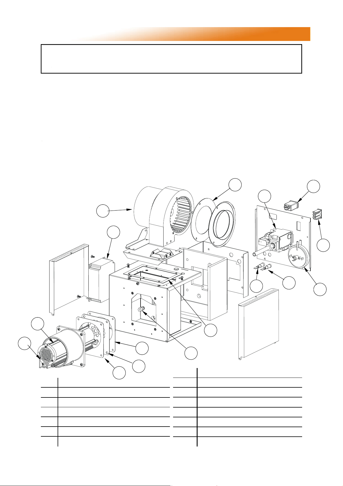
Figure 12. Burner breakdown
I
A
Small Flat
Head
Screwdriver
Manometer
Suitable alternative tools may be used.
Large Adjustable
Spanners or 22, 26 &
27mm Spanners for
Fitting of Gas Flex.
Wrench with
13mm
Socket
M
B
Soft
Brush
N
O
G
F
A Ignition Controller
B Gas Valve
C Burner On Amber Neon
D Power On Red Neon
E Injector
F Burner Tube
G Ignitor Assembly
K
L
K
K
E
H Jet Carrier
I Combustion Fan
J Pressure Switch
K Gaskets
L Burner Orifice Plate
M Fan Orifice Plate
N Mains Input Filter
O Fan Connector
C
n.b. burner insulation
omitted for clarity
D
J
28
Page 29

4.3 Burner Removal
Step 1 Isolate power and gas supplies.
Step 2 Unplug the power connectors.
Step 3 Detach the gas supply as shown below,
taking care to support the burner connection.
Step 6 Slacken the set screw on the burner
support casting to enable the burner to be
removed from the radiant tube.
Step 7 Remove the burner and position
the burner in a safe area to prevent the
burner or components attached to the burner
from falling to the ground.
Step 4 If ducted air is connected, slacken
hose clip and remove the flexible hose from the
burner.
Step 5 slacken the jubilee clip attaching the
pre-heated air hose to the heat exchanger and
remove the flexible hose from the burner.
4.4 Burner Gas Injector Servicing
Step 1.a Remove the burner support casting
and gasket.
Step 1.b The burner head assembly can be
disconnected by separating the connectors of
the ignition lead assembly and removing the
pressure switch silicon tube.
29
Page 30
Step 2 The gas injector can be inspected and
replaced if contaminated or blocked.
When replacing the gas injector ensure
approved thread sealant is used.
replaced ensuring the 5 holes on the outer ring
are aligned alongside the probes.
Step 3 The condition of the igniter assembly can
be checked for deterioration. However, we
advise replacement at each service to ensure
continued reliability. Detach the electrode
assembly from the burner head by removing the
two screws and separating the igniter lead
connectors.
Step 3 Reconnect ignition leads and silicone
tube to test nipple. Refit gasket and support
casting.
4.5 Burner Head and Electrode Servicing
Step 1 Check the pepper pot burner head for
contamination. If necessary this can be
removed. See below. This can be cleaned
together with the Inside of the burner head.
Step 2 The pepper pot burner head can be
10.0°
Ø3”
3/8”
7/64”
±1/64”
Step 4 Refit the electrode assembly and ensure
the connections are secure to prevent arcing of
the spark electrode.
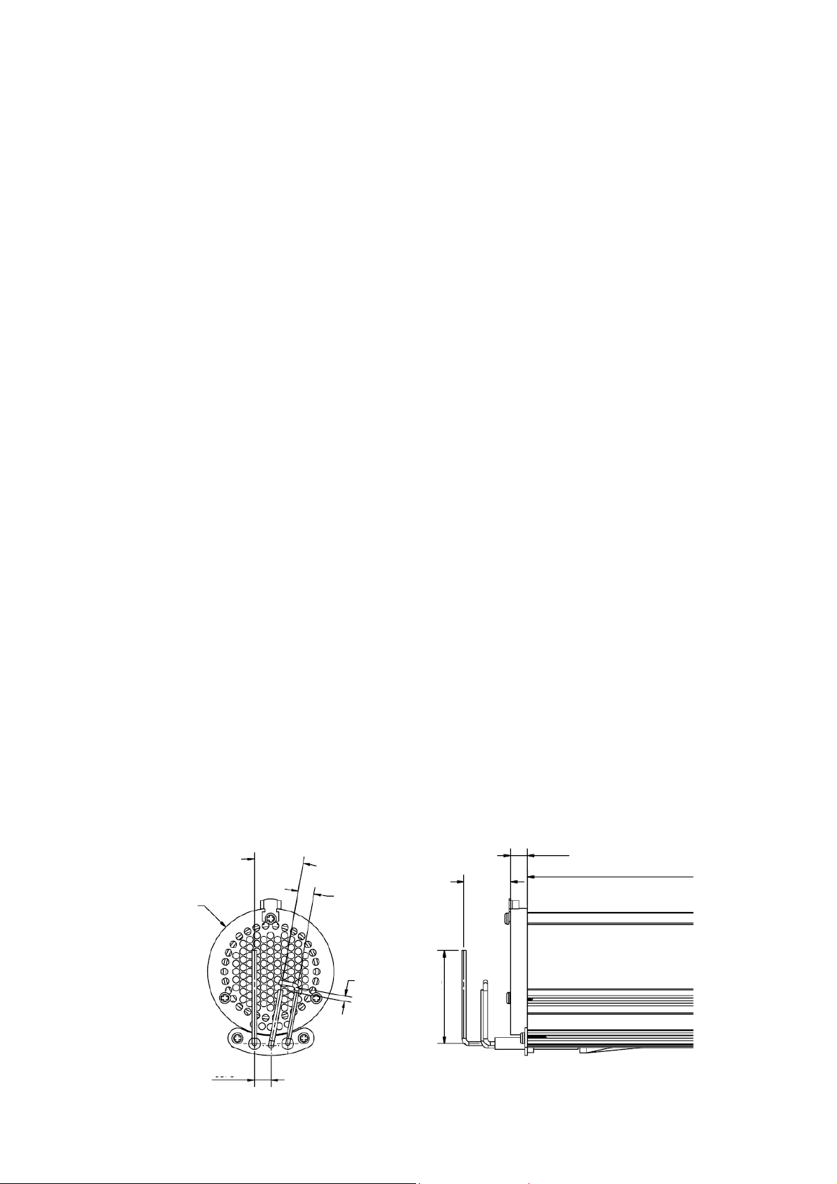
Step 5 Check the positions and spark gap as
shown below.
Step 6 The burner assembly is ready to refit
after servicing the combustion fan and the
radiant tube assembly.
25/64”
1 7/64”
±5/64”
2 13/64” ±13/64”
25/64”
30
Page 31

4.6 Combustion Fan Assembly
Step 1 Slacken jubilee clip and remove the
flexible hose from the fan.
Step 2 Remove fan screws and unplug from
burner box.
Step 7 Ensure the impeller rotates freely.
Step 8 Refit components.
4.7 Radiant Tube Servicing
Step 1 Brush any dust from the exterior of the
tubes.
Step 2 Inspect the fan and burner tubes visually.
If the tubes appear clean, skip to servicing the
reflector.
Step 3 Remove the U bend.
Step 3 The combustion fan can now be
detached.
Step 4 Remove the fan orifice plate spigot and
spinning.
Step 5 Inspect the impeller and remove any
dust with a soft brush.
Step 6 Remove any dust from fan scroll and
from around the motor.
Step 4 Withdraw the turbulators from the
appliance. Carefully noting their condition and
position. Replace turbulators if necessary.
31
Page 32

Step 5 The turbulators should be cleaned with
a soft brush.
Step 3 If required the interior of the tubes can
then be cleaned using an industrial vacuum
cleaner or by using long poles and a scraper.
Step 4 Refit components.
4.8 Heat exchanger Servicing
Step 1 Remove the flue connections
4.9 Reflector Servicing
The condition of the reflectors should be noted.
If necessary the reflectors can be cleaned with a
mild detergent. This can significantly improve
the efficiency of the appliance.
4.10 Sweeping of Flue
Inspect the fresh air inlet duct and vent to
ensure they are free from any blockage or
obstruction. The air inlet terminal and vent
terminal should be inspected to ensure they are
not liable to obstruction.
4.11 Recommissioning After Service
After servicing of the heater has been
undertaken, it will be necessary to
re-commission the heater as detailed in Section
3 of these instructions.
Step 2 Slacken casing support screws and
remove heat exchanger from the radiant tube.
Step 3 Remove any dust and dirt from the
heat exchanger & refit.
32
Page 33
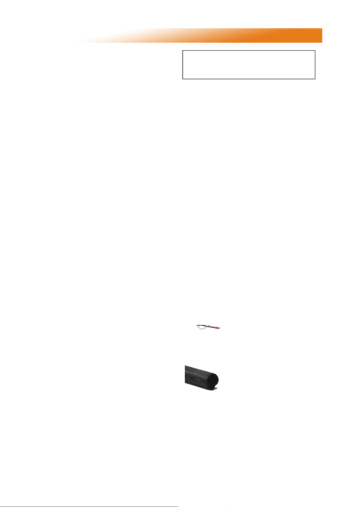
5. Spare Parts.
Required Spares
In order to aid troubleshooting and servicing we
recommend that the components shown in this
section should be stocked.
Item
Ignition
Controller
Nat Gas Valve
Twin sol reg
220/240
Part No. Description
2015S
201857
200988 Pepperpot Head
Note Any spare part components that are
not approved by AmbiRad could invalidate
the approval of the appliance and validity of the
warranty.
Item
Amber Neon
(Burner On)
Red Neon
(Mains On)
Part No. Description
201676 Pressure Switch:
2175
2180
Extruded Burner
Head
Injector
Jet Carrier
(all except *)
Jet Carrier *
VSX50 ONLY
201284 Ignitor Assembly
200358
See
section 1.10
200420
201630
Combustion Fan
Cables:
Spark Electrode
(black)
Rectification lead
(purple)
Earth lead
(green/yellow)
See
Section 1.10
201488 Gasket Set
900225-2
900225-3
900225-1
201321 Ducted Air Hose
Flame Plate
(20/25 ONLY)
Turbulators
Burner tube
Fan tube 25/30/50
Fan tube others
201358
6618T
200015T
6619T
7541 Hose Clamp
33
Page 34
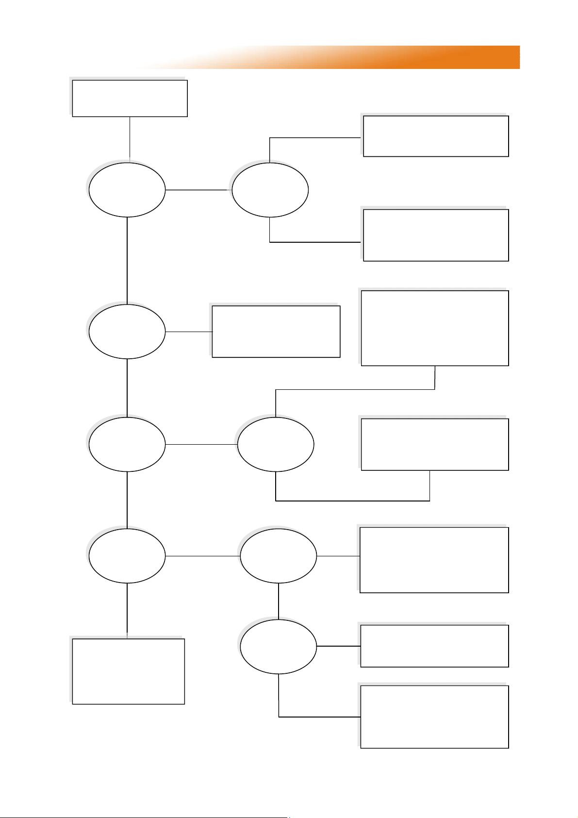
6. Fault Finding Guide.
Ensure gas & electricity
supplies are enabled.
YES
Does the RED
neon
illuminate?
YES
Does the
combustion fan
run?
YES
NO
NO
YES
Is there power
on the burner?
NO
Check:
1. Wiring harness & plugs
2. Vacuum switch operation
3. Replace fan
NO
Check:
1. Burner controller
2. Red neon faulty
Check:
1. Operation of any thermostat
2. Any external fuses
3. Correct voltage is selected
Check:
1. Vacuum switch tubes
2. Emitter tubes, air inlet & flue
for obstructions
3. Operation of vacuum switch
4. Replace combustion fan
Does the
amber light
illuminate after
10s purge?
YES
Does the
amber light
illuminate for 10s
then go out?
NO
If the heater still fails to
operate normally,
please contact
the AmbiRad
service department.
NO
YES
Does the
vacuum switch
`pull in`?
Is the burner
sparking?
YES
Does the gas
valve open?
YES
YES
NO
NO
Check:
1. Burner controller
2. Wiring harness
3. Amber neon faulty
Check:
1. Integrity of spark leads
2. Integrity of electrode
assembly & spark gap
3. Burner controller
Check:
1. Burner controller
2. Replace gas valve
Check:
1. Burner inlet pressure
2. Burner nozzle pressure
3. Check live & neutral polarity
4. Check presence of good earth
34
Page 35

7. Replacing Parts.
Turn of gas any electrical supplies to
the heater before starting repair work.
7.1 Burner Controller Replacement
Step 1 Slacken screw in burner lid and open the
right hand burner access door.
Step 2 Undo 2 screws from controller bracket
and remove. Disconnect burner controller from
the wiring harness.
Step 6 Refit HT leads and refit burner controller
to wiring harness.
Step 7 Test product and close access doors.
7.2 Air Pressure Switch Replacement
Step 1 Disconnect the two silicone impulse
tubes and three wiring connections making note
of replacement positions.
Step 3 Disconnect the HT Lead from burner
controller.
Step 4 Remove the four screws attaching the
controller to the bracket and remove.
Step 2 Remove the two screws as shown below.
Step 3 The air pressure switch can now be
removed.
Step 4
Fit the new air
pressure switch
ensuring the
impulse tubes are
connected as
shown opposite.
Step 5
Test product and
close access
doors.
Step 5 Fit new burner controller
35
Page 36

7.3 Gas Valve Replacement
Step 1 Remove the burner assembly as
described in the section 4.3 Servicing.
Step 2 Open the left hand access door and
detach the impulse hoses from the air pressure
switch.
Step 3 Remove the 4 screws holding the burner
head onto the burner assembly and carefully
pull burner head assembly from housing.
Step 5 From within the combustion chamber,
remove the two screws holding the front of the
gas valve.
Step 6 Turning the housing over, remove the
four screws holding the rear burner plate in
position.
Step 4 The burner head can now be detached
by disconnecting the impulse tube and the
burner head wiring (ignition and rectification
leads).
Step 7 Open the two side doors and remove the
rear plate assembly.
Step 8 Whilst the valve is still attached to the
plate, the jet carrier, gas inlet, and wiring
harness can now be detached from the gas
valve.
36
Page 37
Step 9 The two screws retaining the gas valve
can then be removed.
Step 10 The gas valve can now be replaced.
Step 11 Refit all components in reverse order.
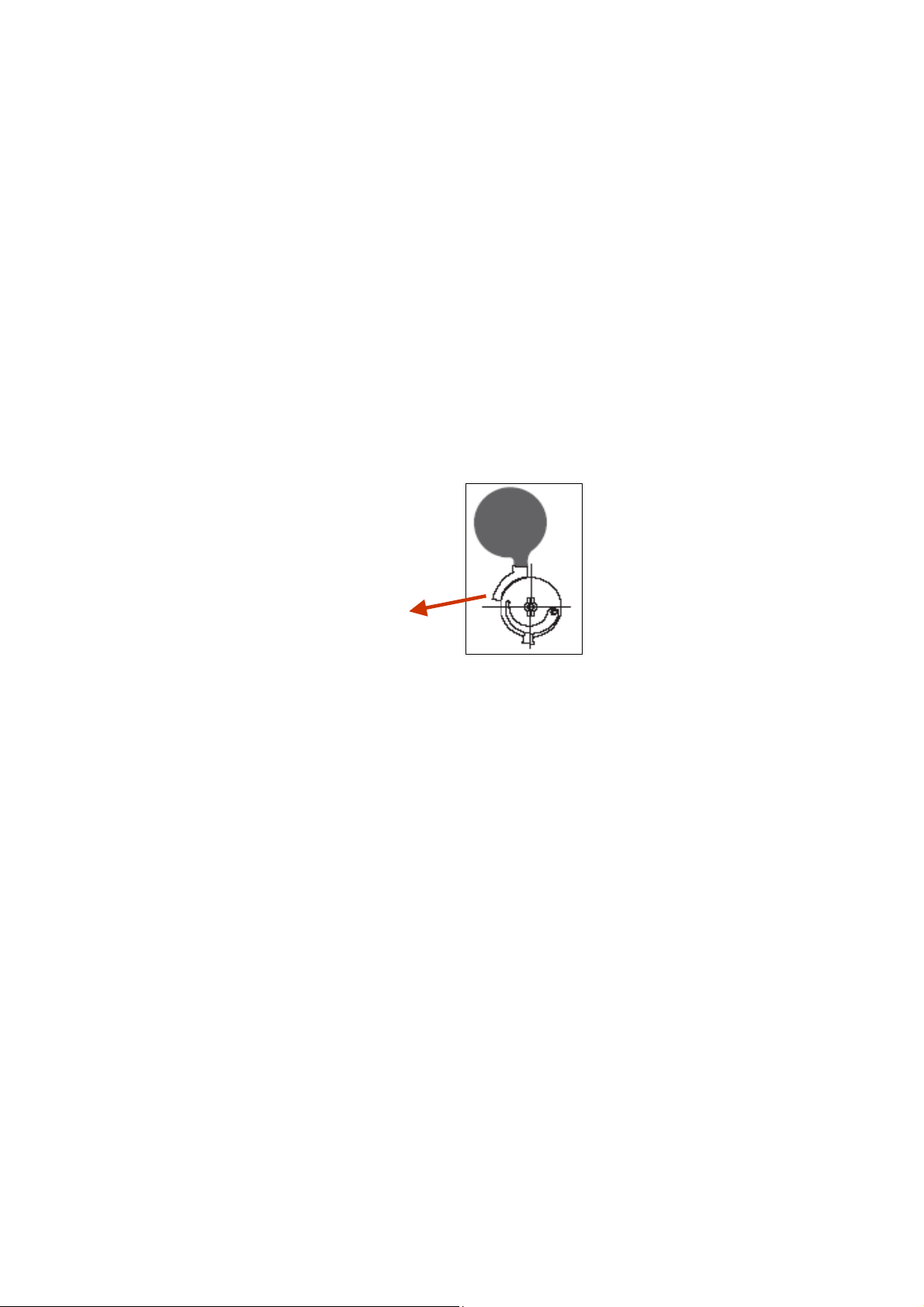
Step 12 Ensure step screw is in the correct
position as indicated in the diagram below.
Step 13 Set gas pressures to data badge or as
per section 1.11 and ensure reliable burner
performance.
Step 14 Test product and close access doors.
Step Screw
Adjustment
37
Page 38

Notes
38
Page 39

Notes
39
Page 40

8. User & Operating Instructions.
8.1 To Start the Heater
1. Ensure gas supply is turned on.
2. Electrical supply to the controls is on.
3. Ensure that the controls are correctly set
i.e.;
• Clock is correctly set.
• Heater program is correctly set.
• Required room temp is correctly set
4. Once the heating controller ‘calls for heat’
power will be supplied to the heater(s). The
red neon will then illuminate.
5. After a pre-purge period of 10 seconds the
burner will ignite and the amber neon will
then illuminate.
6. If lockout occurs press the lockout reset
button (if available), or switch off electrical
supply and restart after 15 seconds.
7. If lockout occurs three times consecutively
switch off and isolate the gas and
electricity supplies.
Contact the AmbiRad Service department.
8.2. To Switch Off Heater
1. Switch off electrical supply to the heater.
The burner will stop and the fan will shut
off.
2. If the heater is to be switched off for
periods in excess of one week it is highly
recommended that both the gas and the
electrical supplies are turned off.
8.3. Routine Maintenance between Service
Intervals
After ensuring that the heater is cold and
mains electric isolated, cleaning of the
reflectors with a soft cloth and a mild
detergent (non solvent based cleaners only)
in water can be undertaken.
Additional removal of dust from the radiant
tubes, burner and heat exchanger can be
undertaken.
8.4 Frequency of Servicing
The manufacturer recommends that to
ensure continued efficient and safe
operation of the appliance, the heater is
serviced annually by a competent person
e.g. every year in normal working conditions
but in exceptional dusty or polluted
conditions more frequent servicing may be
required.
The manufacturer offers a maintenance
service. Details are available on request.
For Service requirements, please contact
AmbiRad.
For further technical and service support
visit our Support Information Database at
www.s-i-d.co.uk
AmbiRad Limited Fens Pool Avenue
Brierley Hill West Midlands DY5 1QA
United Kingdom.
Telephone 01384 489700
Facsimile 01384 489707
Email [email protected]
Website www.ambirad.co.uk
Technical Support www.s-i-d.co.uk
AmbiRad is a registered trademark of AmbiRad Limite d. Because of continuous product
innovation, AmbiRad reserve the right to change product specification without due notice
40
Document reference number GB/VS/190/0112
 Loading...