

Page 1

SERVICING & COMMISSIONING MANUAL
FOR VISION
®
VS RANGE
OF RADIANT TUBE HEATERS
INDEX Section
Introduction & Document Index
Installation Requirements-------------------------------------------------1
Commissioning Instructions----------------------------------------------2
Servicing Instructions------------------------------------------------------3
Spare Parts-------------------------------------------------------------------4
Fault Finding Guide --------------------------------------------------------5
Replacing Parts -------------------------------------------------------------6
User and Operating Instructions ----------------------------------------7
WARNINGS
AmbiRad equipment must be installed and maintained in accordance with the relevant
provisions of the Gas Safety (Installations and Use) Regulations 1998 for gas fired products.
Due account should also be taken of any obligations arising from the Health and Safety at
Works Act 1974 or relevant codes of practice. In addition the installation must be carried out
in accordance with the current IEE wiring regulations (BS 7671), BS 6896:2005 (Industrial &
Commercial) and any other relevant British Standards and Codes of Practice by a qualified
installer. All external wiring MUST comply with the current IEE wiring regulations.
Page 2

Introduction.
Welcome to the new range of high efficiency
AmbiRad Vision radiant tube heaters. Local
regulations may vary in the country of use and
it is the installers responsibility to ensure that
such regulations are satisfied
All installation, assembly, commissioning and
service procedures must be carried out by
suitable qualified competent persons to the
statutory regulations in the country of use.
When assembling, installing, commissioning
and servicing is undertaken on radiant tube
heaters specified in these instructions, due care
and attention is required to ensure that working
Document Index.
1 Installation Requirements
1.1 Health & Safety
1.2 Model definitions
1.3 Technical Details
2 Commissioning Instructions
2.1 Tools Required
2.2 Balancing the Herringbone System
2.3 Balancing a DL System
2.4 Commissioning Chart for VS Unitary Heaters
3 Servicing Instructions
3.1 Tools required
3.2 Burner Description
3.3 Burner Removal
3.4 Burner Gas Injector Servicing
3.5 Burner Head and Electrode Servicing
3.6 Combustion Fan Assembly Induced Burner
at height regulations are adhered to at the
mounting heights specified.
PLEASE READ this document prior to
installation to familiarise yourself with the
components and tools you require at the various
stages of assembly.
All Dimensions shown are in mm unless
otherwise stated.
The manufacturer reserves the right to alter
specifications without prior notice.
3.7 Combustion Fan Assembly Forced Burner
3.8 Radiant Tube Servicing
3.9 Reflector Servicing
3.10 Inspection of Flue
3.11 Re-commissioning after Service
4 Spare Parts
5 Fault Finding Guide
6 Replacing Parts
6.1 Burner Controller Replacement
6.2 Air Pressure Switch Replacement
6.3 Gas Valve Replacement
7 User and Operating Instructions
7.1 To Start Heater
7.2 To Switch off Heater
7.3 Routine Maintenance Between Service Intervals
7.4 Frequency of Servicing
1. Installation Requirements.
Isolate any electrical supply to the
heater and controller before proceeding.
1.1 Health and Safety
AmbiRad heaters must be installed in
accordance with the relevant provisions of the
Gas Safety (Installations and Use) Regulations
1998. Due account should also be taken of any
obligations arising from the Health and Safety
at Works Act 1974 or relevant codes of
practice. In addition the installation must be
carried out in accordance with the current IEE
wiring regulations (BS 7671), BS 6896:2005
(Industrial & Commercial) and any other
relevant British Standards and Codes of
Practice by a qualified installer. Isolate all
electrical supplies to the heater & controller
before proceeding.
For your own safety we recommend the use of
safety boots and leather faced gloves when
handling sharp or heavy items. The use of
protective eye wear is also recommended.
1.2 Model Definitions
VSUT = AmbiRad Vision U Tube heater with
painted induced burner, stainless steel reflector
& end caps.
VSUH = AmbiRad Vision U Tube heater in Herringbone manifold configurations with painted
induced burner, stainless steel reflector & end
caps.
VSLI = AmbiRad Vision Single Linear heater
with painted induced burner, stainless steel reflector & end caps.
VSLF = AmbiRad Vision Single Linear heater
with painted Forced burner, stainless steel reflector & end caps. (Nat Gas ONLY)
VSLH = AmbiRad Vision Linear heater in Herringbone manifold configurations with painted
induced burner, stainless steel reflector & end
caps.
VSDL = AmbiRad Vision Double Linear heater
with painted induced burner, stainless steel reflector & end caps.
VSAUT, VSAUH, VSALI, VSALF, VSALH &
VSADL = As above except: aluminised reflector
with no end caps.
2
Page 3

1.3 Technical Details.
Tables 1a/b/c/d & e - Natural Gas (G20)
No of Injectors
Gas Connection
Flue Nominal Bore mm (in)
Unitary Fan Motor Details
Heater
Model
VS(A)15UT4
VS(A)15UT
VS(A)20UT
VS(A)25UT
VS(A)30UT
VS(A)35UT
VS(A)40UT
VS(A)45UT
VS(A)50UT
Heat Input kW
Gross Nett
1
½ in BSP Internal thread
125 (5)
230 volt 1 phase 50Hz
Gas
Flowrate
(m³/hr)
15.8 14.2 1.5 11.1 1.3 260x2219x670 41 0.5 2501
15.0 13.5 1.4 10.7 1.3 240x3417x500 43 0.5 2501
19.5 17.6 1.9 10.8 1.5 240x4142x500 50 0.5 2501
23.5 21.2 2.3 8.0 1.8 240x5066x500 60 1.0 2507
29.5 26.5 2.8 9.5 2.0 240x6029x500 70 1.0 2507
36.0 32.4 3.4 9.7 2.3 260x5709x670 92 1.0 2507
40.0 36.0 3.8 12.2 2.3 260x5709x670 92 1.0 2507
44.0 39.6 4.2 8.9 2.9 260x7471x670 121 0.5 2560
48.0 43.2 4.6 9.1 2.5 260x7471x670 121 0.5 2560
Injector
Pressure
(mbar)
Injector
Size
(mm)
Size
(h x l x w)
Weight
(Kg)
Fan
Rating
(A)
Fan
Type
Heater
Model
VS(A)15LF6
VS(A)15LF8
VS(A)20LF7
VS(A)20LF10-5
VS(A)25LF8
VS(A)25LF10-5
VS(A)30LF10-5
VS(A)30LF12-5
VS(A)35LF10-5
VS(A)35LF13-5
VS(A)40LF13-5
VS(A)40LF16
VS(A)45LF13-5
Heat Input kW
13.8 12.4 1.3 9.8 1.3 390x5984x315 43 0.5 2501
13.8 12.4 1.3 9.8 1.3 390x8022x315 53 0.5 2501
19.5 17.6 1.9 12.0 1.5 390x6992x315 49 1.0 2507
19.5 17.6 1.9 12.0 1.5 390x10662x315 72 1.0 2507
23.5 21.2 2.3 9.5 1.8 390x8022x315 53 0.5 2501
23.5 21.2 2.3 9.5 1.8 390x10662x315 72 0.5 2501
29.5 26.6 2.8 11.5 2.0 390x10662x315 72 1.0 2507
29.5 26.6 2.8 11.5 2.0 390x12652x315 84 1.0 2507
36.5 32.9 3.5 11.5 2.3 390x10892x470 103 0.5 2501
36.5 32.9 3.5 11.5 2.3 390x13492x470 126 0.5 2501
40.0 36.0 3.8 12.5 2.4 390x13492x470 126 1.0 2507
40.0 36.0 3.8 12.5 2.4 390x16092x470 147 1.0 2507
45.0 40.5 4.3 11.0 2.9 390x13492x470 126 1.0 2507
Gas
Flowrate
(m³/hr)
Injector
Pressure
(mbar)
Injector
Size
(mm)
Size
(h x l x w)
Weight
(Kg)
Fan
Rating
(A)
Fan
Type Gross Nett
VS(A)45LF16
VS(A)50LF13-5
VS(A)50LF16
45.0 40.5 4.3 11.0 2.9 390x16092x470 147 1.0 2507
50.0 45.0 4.8 13.6 3.0 390x13492x470 126 1.0 2507
50.0 45.0 4.8 13.6 3.0 390x16092x470 147 1.0 2507
3
Page 4

Heater
Model
VS(A)15LI8
VS(A)20LI7
VS(A)20LI10-5
VS(A)25LI8
VS(A)25LI10-5
VS(A)30LI10-5
VS(A)30LI12-5
VS(A)35LI10-5
VS(A)35LI13-5
VS(A)40LI13-5
VS(A)40LI16
VS(A)45LI13-5
VS(A)45LI16
Heat Input kW
Gross Nett
15.0 13.5 1.4 10.7 1.3 390x7917x315 53 0.5 2501
19.5 17.6 1.9 10.8 1.5 390x6907x315 49 0.5 2501
19.5 17.6 1.9 10.8 1.5 390x10537x315 72 0.5 2501
23.5 21.2 2.3 8.0 1.8 390x7917x315 53 0.5 2501
23.5 21.2 2.3 8.0 1.8 390x10537x315 72 0.5 2501
29.5 26.6 2.8 9.5 2.0 390x10537x315 72 1.0 2507
29.5 26.6 2.8 9.5 2.0 390x12567x315 84 1.0 2507
36.0 32.4 3.4 9.6 2.3 390x10787x470 103 1.0 2507
36.0 32.4 3.4 9.6 2.3 390x13387x470 126 1.0 2507
40.0 36.0 3.8 12.2 2.3 390x13387x470 126 1.0 2507
40.0 36.0 3.8 12.2 2.3 390x16006x470 147 1.0 2507
44.0 39.6 4.2 8.9 2.9 390x13387x470 126 1.0 2507
44.0 39.6 4.2 8.9 2.9 390x16006x470 147 1.0 2507
Gas
Flowrate
(m³/hr)
Injector
Pressure
(mbar)
Injector
Size
(mm)
Size
(h x l x w)
Weight
(Kg)
Fan
Rating
(A)
Fan
Type
VS(A)50LI13-5
VS(A)50LI16
Heater
Model
VS(A)15LH6
VS(A)15LH8
VS(A)20LH7
VS(A)20LH10-5
VS(A)25LH8
VS(A)25LH10-5
VS(A)30LH10-5
VS(A)30LH12-5
VS(A)35LH10-5
VS(A)35LH13-5
VS(A)40LH13-5
50.0 45.0 4.8 10.0 2.5 390x13387x470 126 0.5 2560
50.0 45.0 4.8 10.0 2.5 390x16006x470 147 1.0 2507
Heat Input kW
Gross Nett
15.0 13.5 1.4 10.7 1.3 390x5725x315 42
15.0 13.5 1.4 10.7 1.3 390x7763x315 52
19.5 17.6 1.9 10.8 1.5 390x6733x315 48
19.5 17.6 1.9 10.8 1.5 390x10363x315 71
23.5 21.2 2.3 8.0 1.8 390x7763x315 52
23.5 21.2 2.3 8.0 1.8 390x10363x315 71
29.5 26.6 2.8 9.5 2.0 390x10363x315 71
29.5 26.6 2.8 9.5 2.0 390x12393x315 83
36.0 32.4 3.4 9.6 2.3 390x10633x470 101
36.0 32.4 3.4 9.6 2.3 390x13233x470 124
40.0 36.0 3.8 12.2 2.3 390x13233x470 124
Gas
Flowrate
(m³/hr)
Injector
Pressure
(mbar)
Injector
Size
(mm)
Size
(h x l x w)
Weight
(Kg)
VS(A)40LH16
VS(A)45LH13-5
VS(A)45LH16
VS(A)50LH13-5
VS(A)50LH16
40.0 36.0 3.8 12.2 2.3 390x15832x470 145
44.0 39.6 4.2 8.9 2.9 390x13233x470 124
44.0 39.6 4.2 8.9 2.9 390x15832x470 145
50.0 45.0 4.8 10.0 2.5 390x13233x470 124
50.0 45.0 4.8 10.0 2.5 390x15832x470 145
4
Page 5
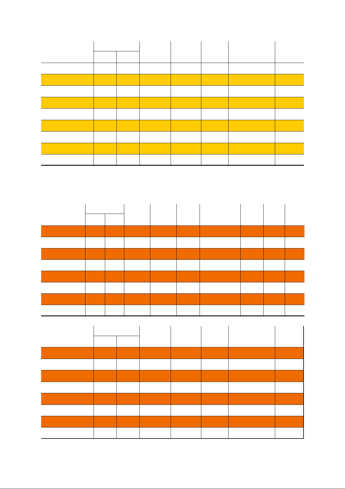
Heater
Model
VS(A)15UH4
VS(A)15UH
VS(A)20UH
VS(A)25UH
VS(A)30UH
VS(A)35UH
VS(A)40UH
VS(A)45UH
VS(A)50UH
Heat Input kW
Gross Nett
15.8 14.2 1.5 11.1 1.3 260x2219x670 40
15.0 13.5 1.4 10.7 1.3 240x3417x500 42
19.5 17.6 1.9 10.8 1.5 240x4142x500 49
23.5 21.2 2.3 8.0 1.8 240x5066x500 59
29.5 26.5 2.8 9.5 2.0 240x6029x500 69
36.0 32.4 3.4 9.7 2.3 260x5709x670 91
40.0 36.0 3.8 12.2 2.3 260x5709x670 91
44.0 39.6 4.2 8.9 2.9 260x7471x670 120
48.0 43.2 4.6 9.1 2.5 260x7471x670 120
Gas
Flowrate
(m³/hr)
Injector
Pressure
(mbar)
Tables 2a/b/c & d. Technical Details - Propane Gas (G31)
Heater
Model
Heat Input kW
Gross Nett
Flowrate
(l/hr)
Injector
Pressure
(mbar)
Injector
Size
(mm)
Injector
Size
(mm)
(h x l x w)
Size
(h x l x w)
Weight
(Kg)
Size
Rating
Fan
(A)
Weight
(Kg)
Fan
Type
VS(A)15UT
VS(A)20UT
VS(A)25UT
VS(A)30UT
VS(A)35UT
VS(A)40UT
VS(A)45UT
VS(A)50UT
Heater
Model
VS(A)15UH
VS(A)20UH
VS(A)25UH
VS(A)30UH
VS(A)35UH
15.2 13.7 2.16 23.7 1.2 240x3417x500 43 0.5 2501
19.2 17.3 2.73 26.1 1.0 240x4142x500 50 1.0 2507
23.5 21.3 3.34 10.8 1.3 240x5066x500 60 1.0 2507
28.0 25.2 3.98 16.2 1.3 240x6029x500 70 1.0 2507
36.0 32.4 5.12 22.4 1.4 260x5709x670 92 0.5 2560
40.0 36.0 5.68 18.4 1.5 260x5709x670 92 0.5 2560
44.0 39.6 6.25 14.9 1.7 260x7471x670 121 0.5 2560
48.0 43.2 6.82 14.3 1.8 260x7471x670 121 0.5 2560
Heat Input kW
Gross Nett
15.2 13.7 2.16 23.7 1.2 240x3417x500 42
19.2 17.3 2.73 26.1 1.0 240x4142x500 49
23.5 21.3 3.34 10.8 1.3 240x5066x500 59
28.0 25.2 3.98 16.2 1.3 240x6029x500 69
36.0 32.4 5.12 22.4 1.4 260x5709x670 91
Flowrate
(l/hr)
Injector
Pressure
(mbar)
Injector
Size
(mm)
Size
(h x l x w)
Weight
(Kg)
VS(A)40UH
VS(A)45UH
VS(A)50UH
40.0 36.0 5.68 18.4 1.5 260x5709x670 91
44.0 39.6 6.25 14.9 1.7 260x7471x670 120
48.0 43.2 6.82 14.3 1.8 260x7471x670 120
5
Page 6
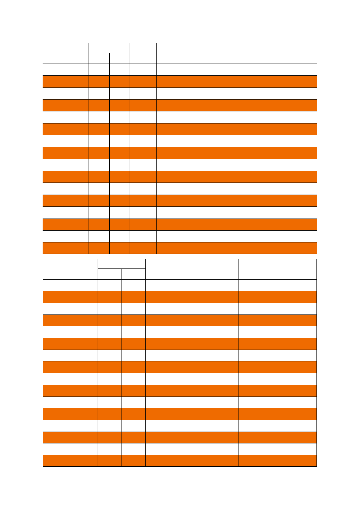
Heater
Model
VS(A)15LI6
VS(A)15LI8
VS(A)20LI7
VS(A)20LI10-5
VS(A)25LI8
VS(A)25LI10-5
VS(A)30LI10-5
VS(A)30LI12-5
VS(A)35LI10-5
VS(A)35LI13-5
VS(A)40LI13-5
VS(A)40LI16
VS(A)45LI13-5
Heat Input kW
15.2 13.7 2.16 23.7 1.2 390x5879x315 43 0.5 2501
15.2 13.7 2.16 23.7 1.2 390x7917x315 53 0.5 2501
19.2 17.3 2.73 26.1 1.0 390x6907x315 49 0.5 2501
19.2 17.3 2.73 26.1 1.0 390x10537x315 72 0.5 2501
23.5 21.2 3.34 10.8 1.3 390x7917x315 53 1.0 2507
23.5 21.2 3.34 10.8 1.3 390x10537x315 72 1.0 2507
28.0 25.2 3.98 16.2 1.3 390x10537x315 72 1.0 2507
28.0 25.2 3.98 16.2 1.3 390x12567x315 84 1.0 2507
36.0 32.4 5.12 22.4 1.4 390x10787x470 103 1.0 2507
36.0 32.4 5.12 22.4 1.4 390x13387x470 126 1.0 2507
40.0 36.0 5.68 18.4 1.5 390x13387x470 126 1.0 2507
40.0 36.0 5.68 18.4 1.5 390x16006x470 147 1.0 2507
44.0 39.6 6.25 14.9 1.7 390x13387x470 126 0.5 2560
Gas
Flowrate
(l/hr)
Injector
Pressure
(mbar)
Injector
Size
(mm)
Size
(h x l x w)
Weight
(Kg)
Fan
Rating
(A) Gross Nett
Fan
Type
VS(A)45LI16
VS(A)50LI13-5
VS(A)50LI16
Heater
Model
VS(A)15LH6
VS(A)15LH8
VS(A)20LH7
VS(A)20LH10-5
VS(A)25LH8
VS(A)25LH10-5
VS(A)30LH10-5
VS(A)30LH12-5
VS(A)35LH10-5
VS(A)35LH13-5
44.0 39.6 6.25 14.9 1.7 390x16006x470 147 0.5 2560
48.0 43.2 6.82 14.3 1.8 390x13387x470 126 0.5 2560
48.0 43.2 6.82 14.3 1.8 390x16006x470 147 0.5 2560
Heat Input kW
15.2 13.7 2.16 23.7 1.2 390x5879x315 42
15.2 13.7 2.16 23.7 1.2 390x7917x315 52
19.2 17.3 2.73 26.1 1.0 390x6907x315 48
19.2 17.3 2.73 26.1 1.0 390x10537x315 71
23.5 21.2 3.34 10.8 1.3 390x7917x315 52
23.5 21.2 3.34 10.8 1.3 390x10537x315 71
28.0 25.2 3.98 16.2 1.3 390x10537x315 71
28.0 25.2 3.98 16.2 1.3 390x12567x315 83
36.0 32.4 5.12 22.4 1.4 390x10787x470 101
36.0 32.4 5.12 22.4 1.4 390x13387x470 124
Flowrate
(l/hr)
Injector
Pressure
(mbar)
Injector
Size
(mm)
Size
(h x l x w) Gross Nett
Weight
(Kg)
VS(A)40LH13-5
VS(A)40LH16
VS(A)45LH13-5
VS(A)45LH16
VS(A)50LH13-5
VS(A)50LH16
40.0 36.0 5.68 18.4 1.5 390x13387x470 124
40.0 36.0 5.68 18.4 1.5 390x16006x470 145
44.0 39.6 6.25 14.9 1.7 390x13387x470 124
44.0 39.6 6.25 14.9 1.7 390x16006x470 145
48.0 43.2 6.82 14.3 1.8 390x13387x470 124
48.0 43.2 6.82 14.3 1.8 390x16006x470 145
6
Page 7
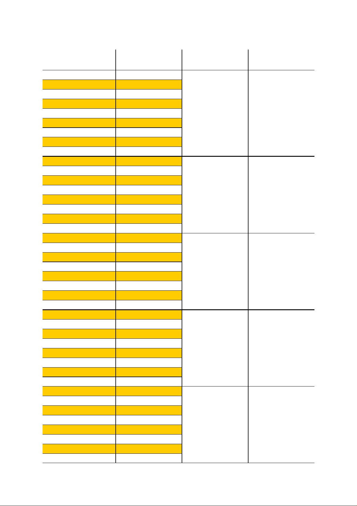
Table 3. Flue details - Natural Gas
Heater Model
VS(A)15UT4
VS(A)15UT
VS(A)20UT
VS(A)25UT
VS(A)30UT
VS(A)35UT
VS(A)40UT
VS(A)45UT
VS(A)50UT
VS(A)15LI6
VS(A)20LI7
VS(A)25LI8
VS(A)30LI10-5
VS(A)35LI10-5
VS(A)40LI13-5
VS(A)45LI13-5
VS(A)50LI13-5
VS(A)15LI8
VS(A)20LI10-5
VS(A)25LI10-5
VS(A)30LI12-5
VS(A)35LI13-5
VS(A)40LI16
VS(A)45LI16
VS(A)50LI16
VS(A)15LF6
VS(A)20LF7
VS(A)25LF8
VS(A)30LF10-5
VS(A)35LF10-5
VS(A)40LF13-5
VS(A)45LF13-5
VS(A)50LF13-5
VS(A)15LF8
VS(A)20LF10-5
VS(A)25LF10-5
VS(A)30LF12-5
VS(A)35LF13-5
VS(A)40LF16
VS(A)45LF16
VS(A)50LF16
Mass Flow Rate of Flue
Gasses (kg/s)
0.0110
0.0115
0.0117
0.0139
0.0171
0.0193
0.0210
0.0212
0.0261
0.0098
0.0119
0.0131
0.0171
0.0207
0.0216
0.0249
0.0256
0.0100
0.0120
0.0145
0.0174
0.0194
0.0214
0.0237
0.0237
0.0075
0.0106
0.0127
0.0130
0.0157
0.0168
0.0189
0.0206
0.0077
0.0105
0.0126
0.0136
0.0161
0.0167
0.0190
0.0207
Flue Pressure (Pa)
Maximum Flue
Resistance
15 - 31
19 - 30 210 - 270
25 -35 160 - 210
18 - 25 250 - 290
20 - 30 180 - 240
Flue Gas Temp (°C)
200 - 250
7
Page 8
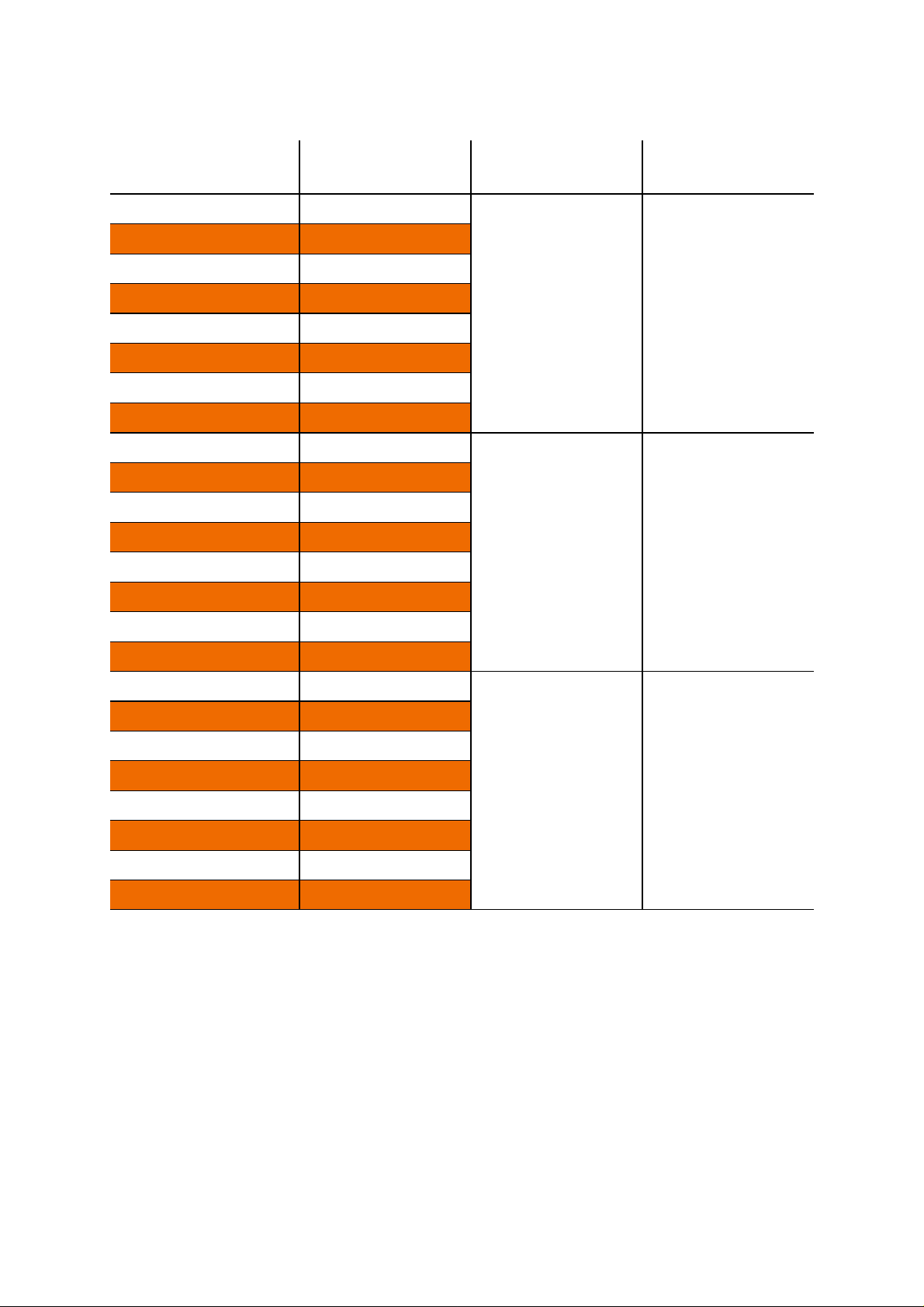
Table 4. Flue details - Propane
Heater Model
VS(A)15UT
VS(A)20UT
VS(A)25UT
VS(A)30UT
VS(A)35UT
VS(A)40UT
VS(A)45UT
VS(A)50UT
VS(A)15LI6
VS(A)20LI7
VS(A)25LI8
VS(A)30LI10-5
VS(A)35LI10-5
VS(A)40LI13-5
Mass Flow Rate of Flue
Gasses (kg/s)
0.0119
0.0132
0.0147
0.0154
0.0264
0.0281
0.0300
0.0300
0.0105
0.0135
0.0126
0.0180
0.0210
0.0220
Flue Pressure (Pa)
Maximum Flue
Resistance
15 - 31 190 - 240
19 - 30 190 - 240
Flue Gas Temp (°C)
VS(A)45LI13-5
VS(A)50LI13-5
VS(A)15LI8
VS(A)20LI10-5
VS(A)25LI10-5
VS(A)30LI12-5
VS(A)35LI13-5
VS(A)40LI16
VS(A)45LI16
VS(A)50LI16
0.0280
0.0263
0.0109
0.0149
0.0137
0.0185
25 - 35 160 - 200
0.0210
0.0224
0.0268
0.0262
8
Page 9
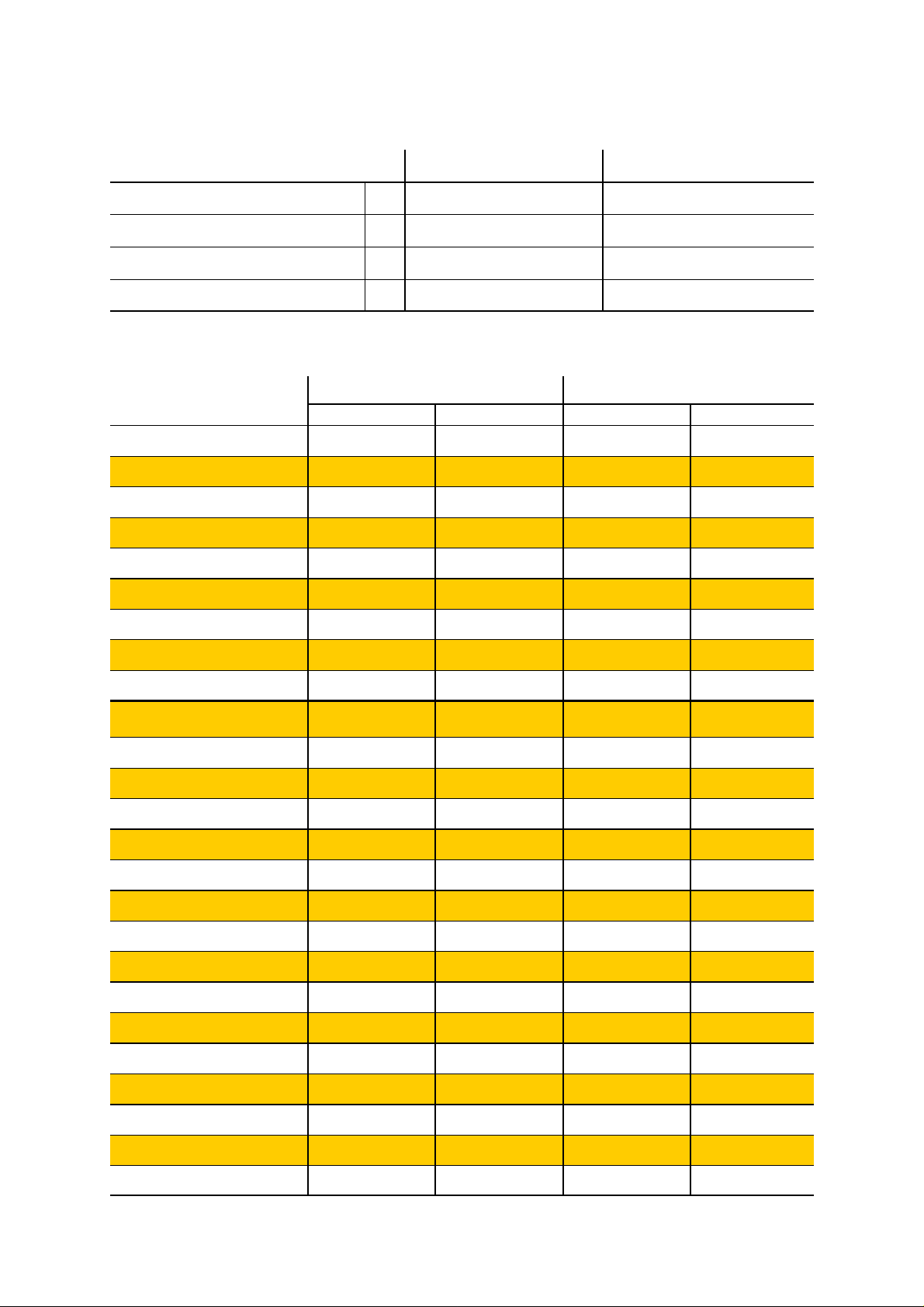
Table 5. Herringbone Vacuum Fan characteristics
Fan type
Power (W) 550 120
Running current (overload setting) (A) 2.6 0.8
Phase Single Single
Voltage (V) 230 230
Type ‘O’ Type ‘2’
Table 6. Herringbone & DL Settings- Natural Gas (G20)
Model
VS(A)15UH4
VS(A)15UH
VS(A)20UH
VS(A)25UH
VS(A)30UH
VS(A)35UH
Cold HB Pressure Hot HB Pressure
O mbar mm H2O mbar
mm H
2
21.4 2.1 12.7 1.2
21.4 2.1 16.3 1.6
19.4 1.9 15.3 1.5
24.5 2.4 20.4 2.0
23.5 2.3 19.4 1.9
25.5 2.5 15.3 1.5
VS(A)40UH
VS(A)45UH
VS(A)50UH
VS(A)15LH6/DL12
VS(A)15LH8/DL16
VS(A)20LH7/DL14
VS(A)20LH10-5/DL21
VS(A)25LH8/DL16
VS(A)25LH10-5/DL21
VS(A)30LH10-5/DL21
VS(A)30LH12-5/DL25
VS(A)35LH10-5/DL21
VS(A)35LH13-5/DL27
VS(A)40LH13-5/DL27
VS(A)40LH16/DL32
29.6 2.9 17.3 1.7
33.0 3.2 23.5 2.3
33.0 3.2 23.5 2.3
18.4 1.8 13.3 1.3
18.4 1.8 14.3 1.4
19.4 1.9 14.3 1.4
18.4 1.8 14.3 1.4
20.4 2.0 16.3 1.6
22.4 2.2 18.4 1.8
24.5 2.4 19.4 1.9
33.6 3.3 25.5 2.5
27.5 2.7 13.3 1.3
20.9 2.0 12.7 1.2
22.4 2.2 12.2 1.2
21.4 2.1 14.3 1.4
VS(A)45LH13-5/DL27
VS(A)45LH16/DL32
VS(A)50LH13-5/DL27
VS(A)50LH16/DL32
27.5 2.7 16.8 1.6
26.5 2.6 17.3 1.7
30.0 2.9 18.3 1.8
27.5 2.7 17.8 1.7
9
Page 10

Table 7. Herringbone & DL Settings- Propane Gas (G31)
Model
VS(A)15UH
VS(A)20UH
VS(A)25UH
VS(A)30UH
VS(A)35UH
VS(A)40UH
VS(A)45UH
VS(A)50UH
VS(A)15LH6/DL12
VS(A)15LH8/DL16
VS(A)20LH7/DL14
VS(A)20LH10-5/DL21
VS(A)25LH8/DL16
VS(A)25LH10-5/DL21
Cold HB Pressure Hot HB Pressure
O mbar mm H2O mbar
mm H
2
21.4 2.1 16.3 1.6
21.4 2.1 16.3 1.6
24.5 2.4 21.4 2.1
26.5 2.6 17.3 1.7
35.7 3.5 21.4 2.1
38.7 3.8 23.5 2.3
37.7 3.7 23.5 2.3
38.7 3.8 24.5 2.4
21.4 2.1 14.3 1.4
19.4 1.9 15.3 1.5
22.4 2.2 15.3 1.5
21.4 2.1 16.3 1.6
22.4 2.2 17.3 1.7
20.4 2.0 16.3 1.6
VS(A)30LH10-5/DL21
VS(A)30LH12-5/DL25
VS(A)35LH10-5/DL21
VS(A)35LH13-5/DL27
VS(A)40LH13-5/DL27
VS(A)40LH16/DL32
VS(A)45LH13-5/DL27
VS(A)45LH16/DL32
VS(A)50LH13-5/DL27
VS(A)50LH16/DL32
28.6 2.8 19.4 1.9
28.6 2.8 20.9 2.0
24.5 2.4 18.4 1.8
21.4 2.1 17.3 1.7
22.4 2.2 18.4 1.8
30.6 3.0 20.9 2.0
34.7 3.4 24.5 2.4
34.7 3.4 23.5 2.3
33.6 3.3 21.4 2.1
30.6 3.0 20.4 2.0
10
Page 11
2. Commissioning Instructions.
These appliances should be commissioned by a qualified engineer.
2.1 Tools Required.
The following tools and equipment are
advisable to complete the tasks laid out in this
manual.
Leather
Faced
Gloves
Pozidrive
Screwdriver
Suitable alternative tools may be used.
Small Flat
Head
Screwdriver
Large Adjustable
Spanners or 22, 26 &
27mm Spanners for
fitting Of Gas Flex.
12mm
Spanner
4mm
Allen
Key
Manometer
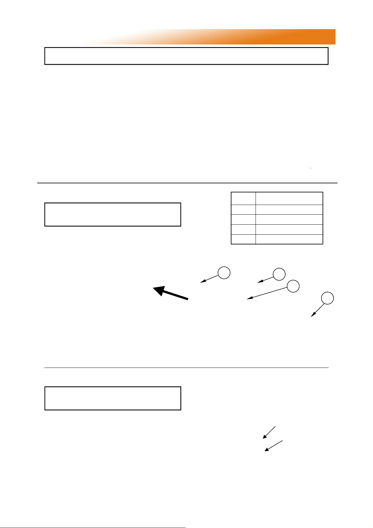
2.2 Balancing The Herringbone System
Important When all the heaters have been
installed the vacuum settings must be
finally balanced in the hot condition.
Before attempting to start up the heating
system it is essential to perform the preliminary
balancing of the vacuum level at each burner
unit. Isolate each heater unit by unplugging the
electrical connector and closing the gas
isolating valve.
Start all burners up and allow them to
run for at least 20 minutes. Adjust the
damper at exit of each heater using a
4mm Allen key in the damper blade
securing screw. Observing the vacuum
reading using a ‘U’ tube manometer connected to the vacuum test point (see figure
29) each damper should be readjusted and
set at a hot condition reading as shown in
table 9 (NG) and table 10 (LPG) for the appropriate size of heater and model.
Wrench with
Extension
Ref Description
A
Radiant Emitter Tube
B
Manifold Tube
C
Vacuum Test Point
D
Damper Blade
Figure 1. HB Damper Assembly
B
D
13mm
Socket
C
A
2.3 Balancing a DL System
Important When all the heaters have been
installed the vacuum settings must be
finally balanced in the hot condition.
As with a Herringbone system above, start both
burners up and allow them to run for at least 20
minutes. Adjust the damper on the condensate
box using a 4mm Allen key in the damper blade
securing screw. Observing the vacuum reading
using a manometer connected to the vacuum
test point (see figure 30) each damper should
be readjusted and set at a hot condition reading
as shown in table 9 (NG) and table 10 (LPG) for
the appropriate size of heater and model.
Figure 2. DL Condensate Box Assembly
Damper blade
Vacuum
test point
11
Page 12
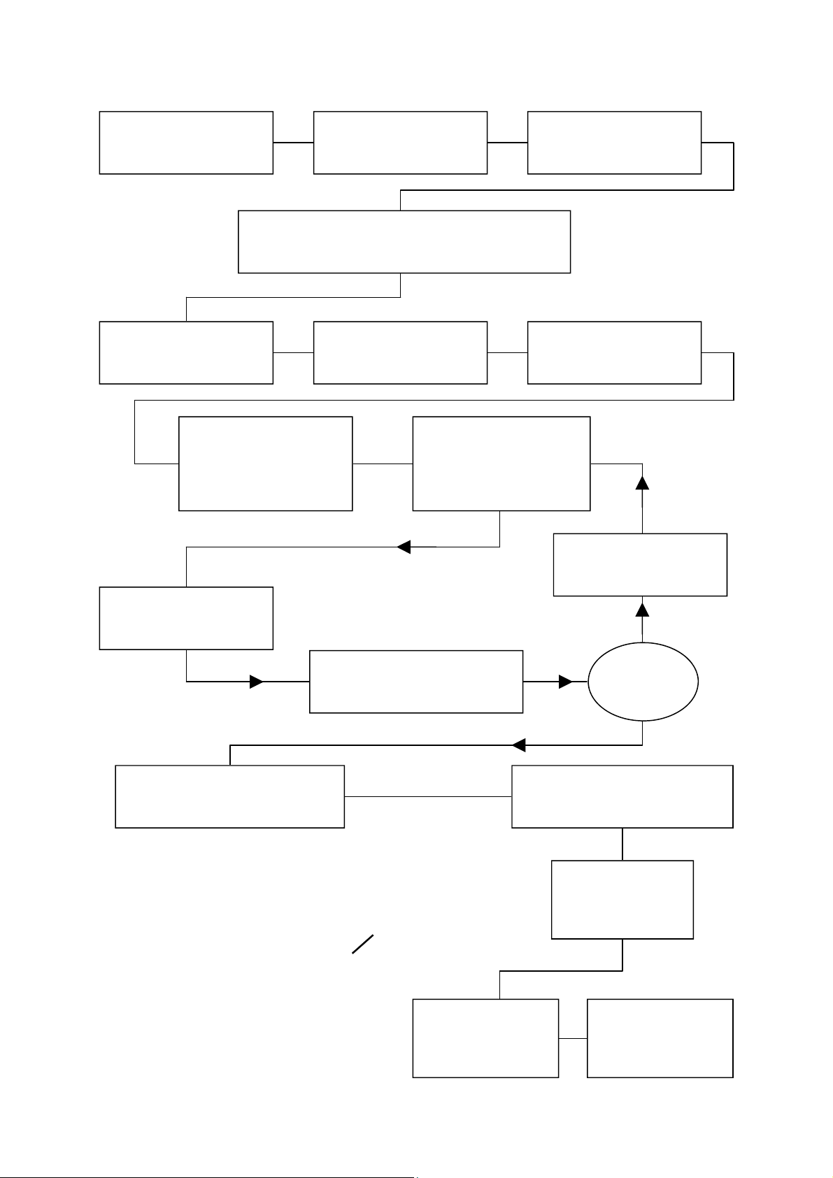
2.4 Commissioning chart for VS series unitary heaters
Check installation has
been carried out to these
instructions.
Remove burner from tube and inspect burner head.
Replace burner on tube
and secure.
Check thermostat is set to
maximum and is calling
for heat.
Ensure gas and electricity
supplies are isolated.
(See servicing instructions)
Reconnect gas hose.
Open isolating valve.
Check soundness.
Switch on electrical supply.
The red neon should now
be illuminated. If restarting
heater a delay of 15s
should be allowed.
Disconnect gas hose from
burner
Open control housing and
check that all components
are securely fastened.
The heater should now
run through its start up
sequence and ignite.
Check gas pressure.
Gas Valve adjustment
A successful ignition is indicated
by the amber light illuminating
and remaining illuminated.
Gas inlet
test point
Turn off power and check
that all components are
securely fastened.
NO
Has the
burner lit?
YES
Check operation on flame failure.
Check gas pressure.
Check operation of
air pressure switch.
Injector pressure
test point.
Adjustment screw under
cap to set injector pressure
Close control housing
12
Leave the instructions
with a responsible
person.
Page 13
3. Servicing Instructions.
These appliances should be serviced annually by a competent person to ensure safe
and efficient operation. In exceptional dusty or polluted conditions more frequent
servicing may be required. The manufacturer offers a maintenance service. Details
available on request
3.1 Tools Required.
Suitable alternative tools may be used.
The following tools and equipment are advisable
to complete the tasks laid out in this manual.
Leather
Faced
Gloves
12mm
Spanner
Pozidrive
Screwdriver
4mm
Allen
Key
Small Flat
Head
Screwdriver
Manometer
Wrench with
13mm
Socket
Large Adjustable
Spanners or 22, 26 &
27mm Spanners for
Fitting of Gas Flex.
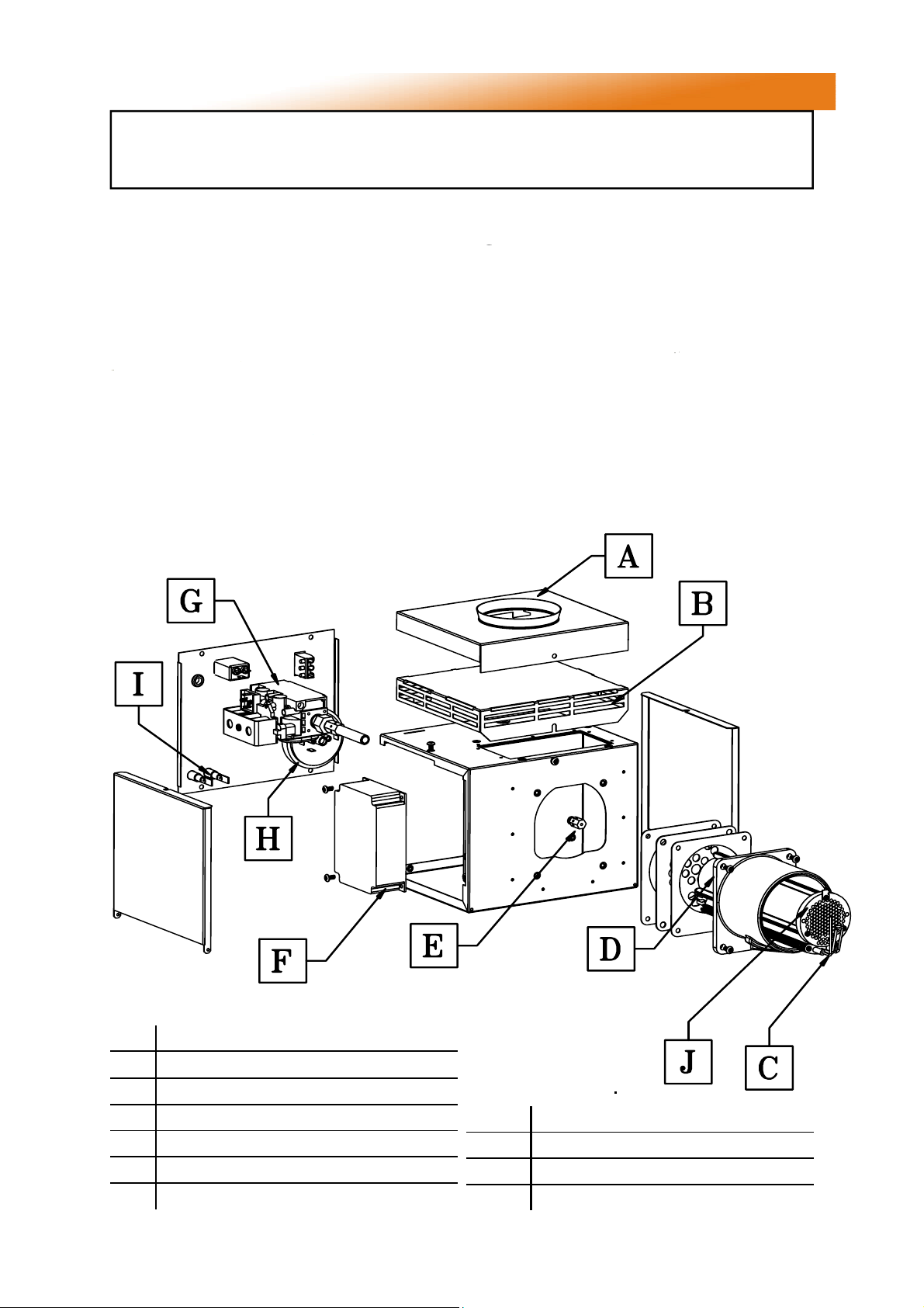
3.2 Burner Description.
Figure 3. Induced Burner: Models VS(A)LI, VS(A)LH, VS(A)UH and VS(A)DL
Soft
Brush
A Ducted Air Inlet
B Induced Air Inlet
Please refer to spares for burner components
C Ignitor Assembly
D Extruded Burner Head
E Multi Hole Injector
F Ignition Controller
G Gas Valve
H Pressure Switch
I Neon's (Red/Amber)
J Pepperpot Head
13
Page 14
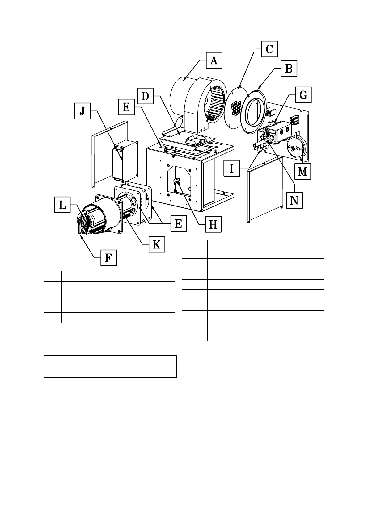
Figure 4. Forced Gas Burner: Model VSLF
A 2501 or 2507 Fan
B Fan Inlet Spigot
C Fan Orifice plate
D Fan Mount Plate and Support
E Gasket Set
3.3 Burner Removal (All Options)
Step 1 Isolate mains electric and gas
supplies. Unplug the fan and mains
electricity connectors.
Please refer to spares for burner components
F Ignitor Assembly
G Gas Valve
H Multi Hole Injector
I Neon's (Red/Amber)
J Ignition Controller
K Extruded Burner Head
L Pepperpot Head
M Pressure Switch
N Jet Carrier
Step 2 Detach the gas supply as shown below,
taking care to support the burner connection.
14
Page 15

Step 3 On forced burners with ducted air attachment slacken jubilee clip and remove the
flexible hose from the fan.
Step 4 Slacken the grub screw on the burner
support casting using a 4mm Allen key to
enable the burner to be removed from the
radiant tube.
the ignition lead assembly and removing the
pressure switch silicon tube.
Step 3 The gas injector can be inspected and
replaced if contaminated or blocked.
Step 5 Carefully remove the burner to prevent it
or any components from falling to the ground
and position the assembly in a safe area.
3.4 Burner Gas Injector Servicing
Step 1 Remove the burner support casting and
gasket.
Step 2 The burner head assembly can be
disconnected by separating the connectors of
When replacing the gas injector use a
12mm spanner and ensure approved
thread sealant is used.
Step 4 Refit the burner support casting and
replace the gaskets to ensure effective sealing.
3.5 Burner Head and Electrode Servicing
Step 1 Check the pepper pot burner head for
contamination. If necessary the head can be
removed for cleaning of the inside of the burner
head, see below.
15
Page 16
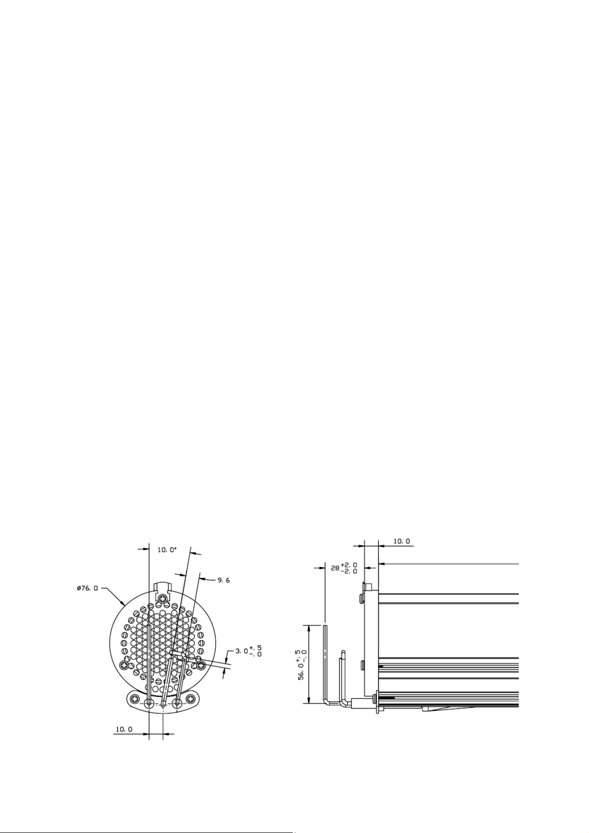
Step 2 The pepper pot burner head can be
replaced ensuring the 5 holes on the outer ring
are aligned alongside the probes.
Step 3 The condition of the ignitor assembly
can be checked for deterioration. However, we
advise replacement at each service to ensure
continued reliability.
Step 4 Detach the electrode assembly from the
burner head by removing the two screws and
separating the ignitor lead connectors.
Step 5 Refit the electrode assembly and ensure
the silicon sleeving is fitted as shown above to
prevent arcing of the spark electrode.
Step 6 Check the positions and spark gap as
shown below.
Step 7 The burner assembly is ready to refit
after servicing the combustion fan and the
radiant tube assembly.
3.6 Combustion Fan Assembly Induced
Burner (Model VSLI/VSALI)
Step 1 Loosen the clamp fitting on the flue
Step 2 Loosen the 4mm grub screw.
Step 3 The combustion fan can now be
detached.
16
Figure 5. Burner head detail
Page 17

Step 4 Remove the fan orifice plate spinning.
Step 5 Inspect the impeller and remove any
dust with a soft brush.
Step 2 Remove fan spigot fixings.
Step 3 The combustion fan can now be
detached.
Step 6 Remove any dust from fan scroll and
from around the motor.
Step 7 Ensure the impeller rotates freely.
Step 8 Refit components.
3.7 Combustion Fan Assembly Forced
Burner (Model VSLF only)
Step 1 On Forced burners with ducted air
attachment slacken jubilee clip and remove the
flexible hose from the fan.
Step 4 Remove the fan orifice plate spinning.
Step 5 Inspect the impeller and remove any dust
with a soft brush.
Step 6 Remove any dust from fan scroll and
from around the motor.
Step 7 Ensure the impeller rotates freely.
Step 8 Refit components.
17
Page 18

3.8 Radiant Tube Servicing
Step 1 Brush any dust from the exterior of the
tubes.
Step 2 Inspect the fan and burner tubes
visually. If the tubes appear clean, skip to
servicing the reflector.
Step 3 Remove the U bend (or damper - HB
products or condensate box - DL products)
Step 4 Withdraw the turbulators from the
appliance. Carefully noting their condition and
position. Replace turbulators if necessary.
Step 6 If required the interior of the tubes can
then be cleaned using an industrial vacuum
cleaner or by using long poles and a scraper.
Step 7 Refit components.
3.9 Reflector Servicing
The condition of the reflectors should be noted.
If necessary the reflectors can be cleaned with a
mild detergent.
This can significantly improve the efficiency
of the appliance.
3.10 Inspection of Flue
The flue needs to be inspected and cleaned if
necessary or in accordance to the regulations of
the country that the appliance is installed.
3.11 Re-commissioning After Service
After servicing of the heater has been
undertaken, it will be necessary to
re-commission the heater as detailed in Section
3 of these instructions.
Step 5 The turbulators should be cleaned with
a soft brush.
18
Page 19

4. Spare Parts.
Required Spares
In order to aid troubleshooting and servicing we
recommend that the components shown in this
section should be stocked.
Item
Ignition
Controller
Nat Gas Valve
Twin sol reg
220/240
Propane Valve
Twin sol reg
220/240
Part No. Description
2015S
201587
201706
200988 Pepperpot Head
Note Any spare part components that are
not approved by AmbiRad could invalidate
the approval of the appliance and validity of the
warranty.
Item
Pressure Switch:
VSLF
All others
Amber Neon
(Burner On)
Red Neon
(Mains On)
Combustion Fan
Part No. Description
M101355
201013
2175
2180
See
Section 1.11
Extruded Burner
Head
Injector
Jet Carrier
(all except *)
Flame Plate
(VS15 ONLY Nat
Gas & Propane)
201284 Ignitor Assembly
200358
See
section 1.11
200420
201358
Cables:
Spark Electrode
(black)
Rectification lead
(purple)
Earth lead
(green/yellow)
Jet Carrier *
VS50
UT/UH/LI/LH/DL
Flame Plate
(VS35/45
Propane ONLY)
201488 Gasket Set
900225-2
900225-3
900225-1
201630
201571
Flame Plate
(VS20/25/30
Propane ONLY)
201854
19
Flame Plate
(VS50
Propane ONLY)
201905
Page 20
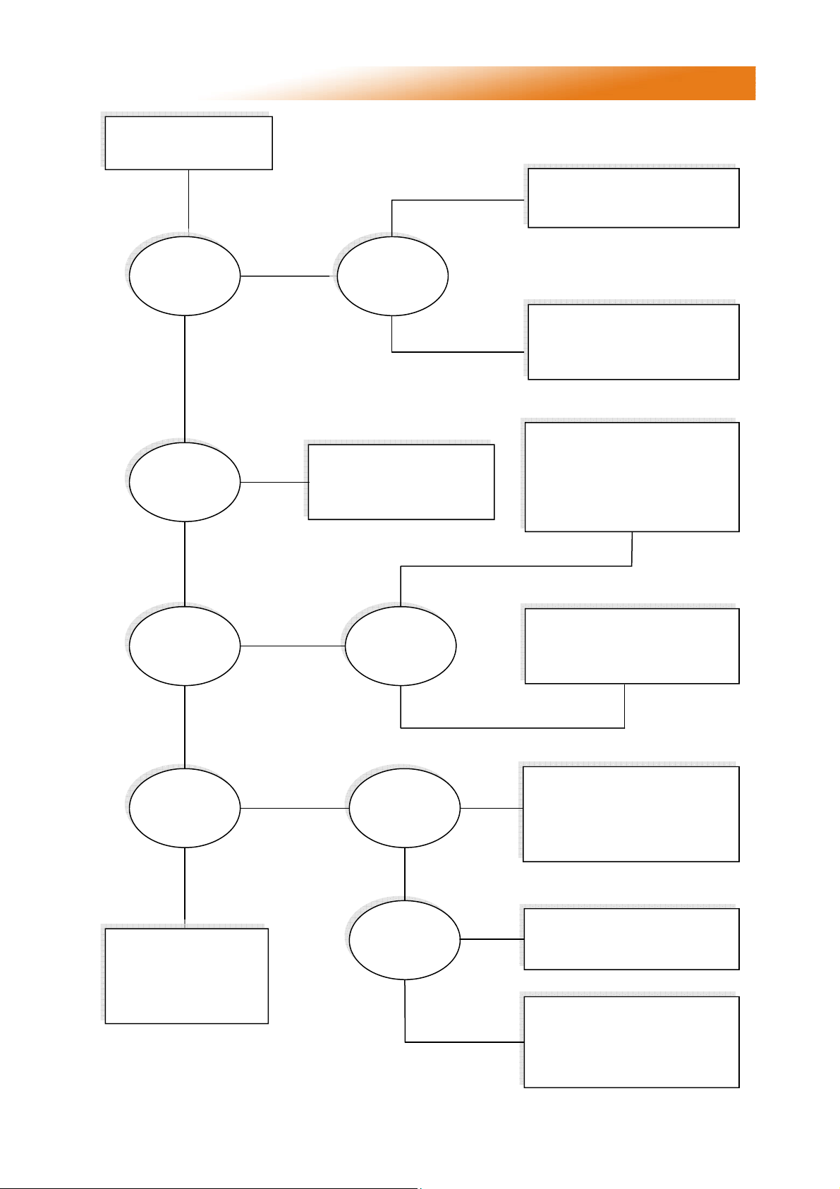
5. Fault Finding Guide.
Ensure gas & electricity
supplies are enabled.
YES
Does the RED
neon
illuminate?
YES
Does the
combustion fan
run?
YES
NO
NO
YES
Is there power
on the burner?
NO
Check:
1. Wiring harness & plugs
2. Vacuum switch operation
3. Replace fan
NO
Check:
1. Burner controller
2. Red neon faulty
Check:
1. Operation of any thermostat
2. Any external fuses
3. Correct voltage is selected
Check:
1. Vacuum switch tubes
2. Emitter tubes, air inlet & flue
for obstructions
3. Operation of vacuum switch
4. Replace combustion fan
Does the
amber light
illuminate after
10s purge?
YES
Does the
amber light
illuminate for 10s
then go out?
NO
If the heater still fails to
operate normally,
please contact
the AmbiRad
service department.
NO
YES
Does the
vacuum switch
`pull in`?
Is the burner
sparking?
YES
Does the gas
valve open?
YES
YES
NO
NO
Check:
1. Burner controller
2. Wiring harness
3. Amber neon faulty
Check:
1. Integrity of spark leads
2. Integrity of electrode
assembly & spark gap
3. Burner controller
Check:
1. Burner controller
2. Replace gas valve
Check:
1. Burner inlet pressure
2. Burner nozzle pressure
3. Check live & neutral polarity
4. Check presence of good earth
20
Page 21

6. Replacing Parts.
6.1 Burner Controller Replacement
Step 1 Slacken screw in burner lid and open the
right hand burner access door.
Step 2 Disconnect burner controller from the
wiring harness.
Step 3 Disconnect the HT Lead from burner
controller.
6.2 Air Pressure Switch Replacement
Step 1 Disconnect the two silicone impulse
tubes.
Step 2 Remove the two screws as shown below.
Step 4 Remove the two screws attaching the
controller to the burner and remove.
Step 5 Fit new burner controller.
Step 6 Refit HT leads and refit burner controller
to wiring harness.
Step 7 Test product and close access door.
Step 3 The air pressure switch can now be
removed.
Step 4 Fit the new air pressure switch ensuring
the impulse tubes are connected as shown
below.
Step 5 Test product and close access doors.
21
Page 22

7.3 Gas Valve Replacement
Step 1 Remove the burner assembly as
described in section 4.3 Servicing.
Step 2 Open the right hand access door and
detach the burner controller from the wiring
harness.
Step 3 Open the left hand access door and
detach the impulse hoses from the air pressure
switch.
Step 6 Detach the two screws holding the front
of the gas valve.
Step 7 Remove the four screws holding the rear
burner plate in position.
Step 4 Remove the 4 screws holding the burner
head onto the burner assembly.
Step 5 The burner head can now be detached
by disconnecting the impulse tube and the
burner head wiring.
Step 8 Remove the rear plate.
Step 9 The jet carrier, gas inlet, and wiring
harness can now be detached from the gas
valve.
Step 10 The two screws retaining the gas valve
can then be removed.
Step 11 The gas valve can now be replaced.
Step 12 Refit all components in reverse order.
22
Page 23
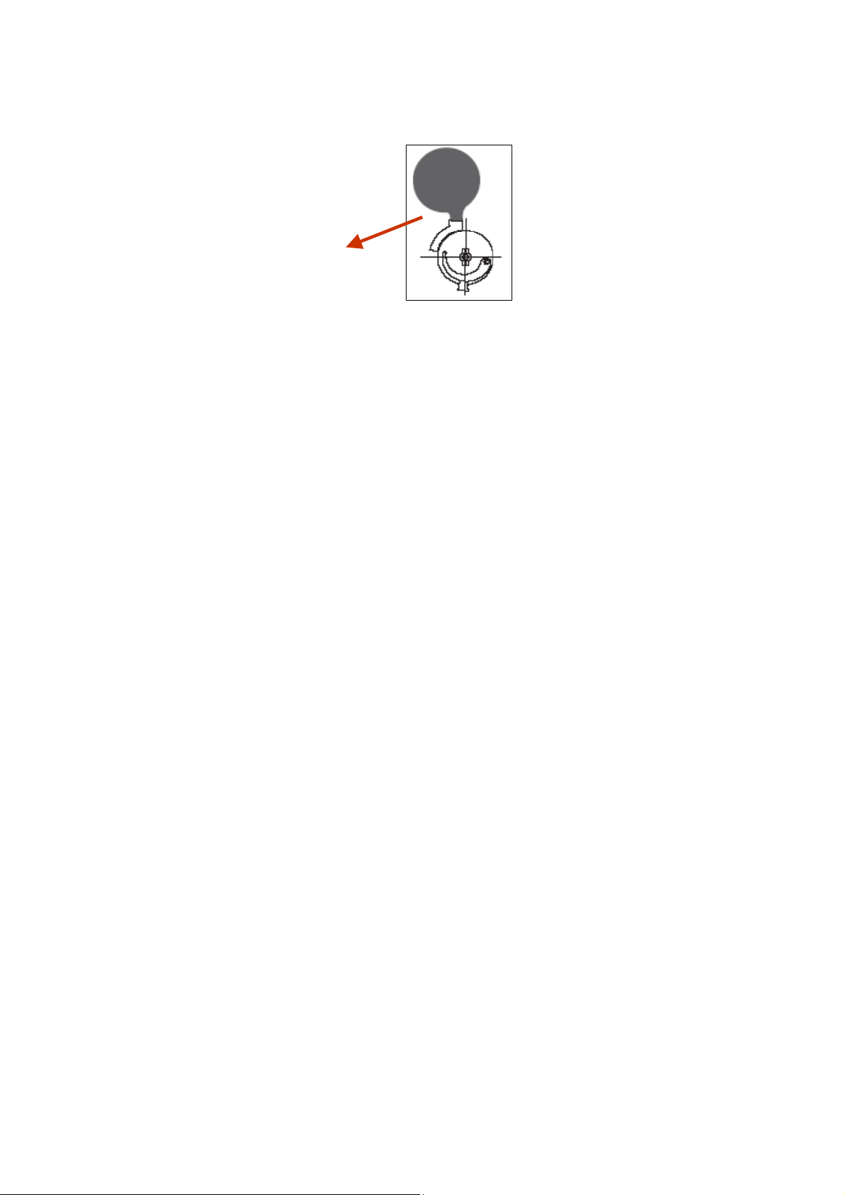
Step 13 Ensure step screw is in the correct
position as indicated in the diagram below. (For
Natural Gas burners ONLY).
Step Screw
Adjustment
Step 14 Set gas pressures to data badge or as
per section 1.3 and ensure reliable burner
performance.
Step 15 Test product and close access doors.
23
Page 24

7. User & Operating Instructions.
7.1 To Start the Heater
1. Ensure gas supply is turned on.
2. Electrical supply to the controls is on.
3. Ensure that the controls are correctly set
i.e.;
• Clock is correctly set.
• Heater program is correctly set.
• Required room temp is correctly set
4. Once the heating controller ‘calls for heat’
power will be supplied to the heater(s). The
red neon will then illuminate.
5. After a pre-purge period of 10 seconds the
burner will ignite and the amber neon will
then illuminate.
6. If lockout occurs press the lockout reset
button (if available), or switch off electrical
supply and restart after 15 seconds.
7. If lockout occurs three times consecutively
switch off and isolate the gas and
electricity supplies.
Contact the AmbiRad Service department.
7.2. To Switch Off Heater
1. Switch off electrical supply to the heater.
The burner will stop and the fan will shut
off.
2. If the heater is to be switched off for
periods in excess of one week it is highly
recommended that both the gas and the
electrical supplies are turned off.
7.3. Routine Maintenance between Service
Intervals
After ensuring that the heater is cold and
mains electric isolated, cleaning of the
reflectors with a soft cloth and a mild
detergent (non solvent based cleaners only)
in water can be undertaken.
Additional removal of dust from the radiant
tubes, burner and heat exchanger can be
undertaken.
7.4 Frequency of Servicing
The manufacturer recommends that to
ensure continued efficient and safe
operation of the appliance, the heater is
serviced annually by a competent person
e.g. every year in normal working conditions
but in exceptional dusty or polluted
conditions more frequent servicing may be
required.
The manufacturer offers a maintenance
service.
Details are available on request.
For Service requirements, please contact
AmbiRad.
For further technical and service support
visit our Support Information Database at
www.s-i-d.co.uk
AmbiRad Limited Fens Pool Avenue
Brierley Hill West Midlands DY5 1QA
United Kingdom.
Telephone 01384 489700
Facsimile 01384 489707
Email [email protected]
Website www.ambirad.co.uk
Technical Suport www.s-i-d.co.uk
AmbiRad is a registered trademark of AmbiRad Limite d. Because of continuous product
innovation, AmbiRad reserve the right to change product specification without due notice
24
Document reference number GB/VS/118S/1208
 Loading...