

Page 1

ASSEMBLY, INSTALLATION & SERVICING
ANUAL FOR AMBIRAD NOR-RAY-VAC
M
ONTINUOUS RADIANT TUBE SYSTEM
C
INDEX Section
Introduction and Document Index
Installation Requirements-------------------------------------------------1
Assembly Instructions------------------------------------------------------2
Commissioning Instructions----------------------------------------------3
Servicing Instructions------------------------------------------------------4
Spare Parts-------------------------------------------------------------------5
Fault Finding Guide --------------------------------------------------------6
Replacing Parts -------------------------------------------------------------7
User and Operating Instructions ----------------------------------------8
WARNINGS
AmbiRad equipment must be installed and maintained in accordance with the relevant
provisions of the Gas Safety (Installations and Use) Regulations 1998 for gas fired products.
Due account should also be taken of any obligations arising from the Health and Safety at
Works Act 1974 or relevant codes of practice. In addition the installation must be carried out
in accordance with the current IEE wiring regulations (BS 7671), BS 6896 (Industrial &
Commercial) and any other relevant British Standards and Codes of Practice by a qualified
installer. All external wiring MUST comply with the current IEE wiring regulations.
Page 2

Document Index.
1 Installation Requirements
1.1 Health & Safety
1.2 Burner Model Definitions
1.3 Heater Suspension
1.4 Clearance to Combustibles
1.5 Gas Connection & Supply Details
1.6 Electrical Connections
1.6.1 Typical Wiring Schematic
1.6.2 Wiring Details
1.7 Ventilation Requirements
1.8 Exhaust & Air Inlet Options
1.8.1 Exhaust Flue Considerations
1.8.2 Ducted Air Inlet Considerations
1.9 Vacuum Fan Details
1.10 Technical Data
2 Assembly Instructions
2.1 Tools Required
2.2 Assembly Notes
2.2.1 Tubes
2.2.2 Couplers
2.2.3 Reflectors
2.2.3.1 Main Reflectors
2.2.3.2 Perimeter Reflectors
2.2.3.3 Corner Reflectors
2.2.3.4 Tee Reflectors
2.2.4 Brackets
2.2.4.1 Suspension Brackets
2.2.4.2 Reflector Support Brackets
2.2.5 Burner
2.2.5.1 LR Burner
2.2.5.2 Burner Head
2.2.6 End Vent Module
2.2.7 Exhaust Fan
2.3 Installation of End Vent/In-line Section
2.4 Installation of Radiant Tube to Tail Pipe
2.5 Installation of Main Reflectors
2.6 Installation of Corner Reflector
2.7 Installation of Tee Reflector
2.8 Final Fixture and Adjustments
2.9 Installation of Fan Exhaust System
2.9.1 Vertical Discharge
2.9.2 Horizontal Discharge
2.9.3 Fan Mounting
2.9.4 Condensate Trap
2.10 Full Breakdown of Typical System
2.11 Installation of End Vent and In-line Burners
2.12 Installation of End Vent Module (EVM)
2.13 Installation of Ducted Air Adaptors
2.13.1 Burner Assembly Adaptor
2.13.2 End Vent Module Adaptor
2.14 Installation of Ball Guard System
2.14.1 Installation
2.14.2 Blanking Shield
2.15 Installation of Slimline Decorative Grille System
2.15.1 Standard Modular Assembly
2.15.2 Shortened Assemblies
2.16 Installation of Blanking Shields
2.17 Installation of Undershield Deflectors
2.18 Installation of Vacuum Fan Acoustic Booth
2.18.1 Dis-assembly
2.18.2 Re-Assemble
2.18.3 Suspension instructions
2.19 Fan Exhaust Silencer
2.19.1 Assembly
2.19.2 Horizontal Configuration
2.19.3 Vertical Configuration
2.20 Fan Motor Muff
2.21 End Vent Silencer
3 Commissioning Instructions
3.1 Tools Required
3.2 General
3.3 Commissioning Procedure
3.3.1 Start Up Checks
3.3.1.8 Burner Timer Dip-switch Settings
3.4 B80/B160 & B300 Inverter Set Up
3.5 BH300 Non-Inverter Set Up
3.6 Final Commissioning
3.7 Typical Unequal Balanced System Layout
4 Servicing Instructions
4.1 Tools Required
4.2 Burner Exploded Views
4.3 Vacuum Fan
4.4 Radiant Tubes
4.5 Tube Couplers
4.6 Reflectors
4.7 Flue Condensate
4.8 Burner Electrodes
4.9 Burner Head
4.10 Filters
4.11 Combustion Chamber Viewing Window
5 Spare Parts
5.1 Required Spares List
5.2 Injector/Air Shutter Selection
6 Fault Finding Guide
7 Replacing Parts
7.1 Removal of Burner Assembly
7.2 Gas Valve Replacement
7.3 Filter Replacement
7.4 Controller Replacement
7.5 Pressure Switch Replacement
7.6 Sequence Timer Replacement
7.7 Electrode Assembly Replacement
7.8 Injector Replacement
7.9 Combustion Chamber Window Replacement
8 User and Operating Instructions
8.1 To Start Heater
8.2 To Switch Off Heater
8.3 Routine Maintenance Between Service Intervals
8.4 Frequency of Servicing
2
Page 3
Introduction.
Welcome to the range of Nor-Ray-Vac ‘LR’
series continuous radiant tube heaters. The
Nor-Ray-Vac ‘LR’ series system complies with
the requirements of the European Gas
Appliance Directive BS EN777-4. Local
regulations may vary in the country of use and it
is the installers responsibility to ensure that
such regulations are satisfied.
All installation, assembly, commissioning and
service procedures must be carried out by
suitable qualified competent persons to the
statutory regulations in the country of use.
When assembling, installing, commissioning and
servicing is undertaken on radiant tube heaters
specified in these instructions, due care and
attention is required to ensure that working at
height regulations are adhered to at the
mounting heights specified.
PLEASE READ this document prior to
installation to familiarise yourself with the
components and tools you require at the various
stages of assembly.
All Dimensions shown are in mm unless
otherwise stated.
The manufacturer reserves the right to alter
specifications without prior notice.
The Ambi-Rad Nor-Ray-Vac ‘LR’ series direct
gas fired radiant heating system comprises of a
continuous system with a number of burners
located in series in a radiant branch, and a
number of radiant branches manifolded
together, linked by a tail pipe to a vacuum fan
discharging the spent products of combustion to
atmosphere. A system may comprise of just one
burner and one vacuum fan, to multiple burners
in multiple radiant branches with one or more
vacuum fans.
To enable exact matching of operational needs
within an area, distances between burners and
ratings of the burners can vary. The unique
feature of Nor-Ray-Vac ‘LR’ series is a radiant
system which provides uniform heat coverage of
the floor area, eliminating hot/cold spots.
The tube into which the burners are mounted
and over which the reflectors are fitted and
emits the maximum heat is called the radiant
tube. The radiant heat emitted from the hot tube
is directed downwards by reflectors. The
remaining interconnecting tube is called the tail
pipe and radiates with less intensity.
The operating temperatures of the tubes
generally range from 200°C – 480°C max.
The action of the vacuum fan is three fold; to
create a high negative pressure within the
radiant tube and tail pipe so as to discharge the
spent products of combustion from the system
to a point outside the building being heated; to
control the flow of gas and air through each
burner in stoichiometric proportions; to draw
carrier air into the tube system at the start of
each radiant branch, in order to distribute the
heat from the flame along the tube.
1. Installation Requirements.
Isolate any electrical supply to the
heater and controller before proceeding.
1.1 Health and Safety
AmbiRad heaters must be installed in
accordance with the relevant provisions of the
Gas Safety (Installations and Use) Regulations
1998.
Due account should also be taken of any
obligations arising from the Health and Safety
at Works Act 1974 or relevant codes of
practice. In addition the installation must be
carried out in accordance with the current IEE
wiring regulations (BS 7671), BS 6896:
(Industrial & Commercial) and any other
relevant British Standards and Codes of
Practice by a qualified installer. Isolate all
electrical supplies to the heater & controller
before proceeding.
For your own safety we recommend the use of
safety boots and leather faced gloves when
handling sharp or heavy items. The use of
protective eye wear is also recommended.
1.2 Burner Model Definitions
NRVxxLR-EV = Nor-Ray-Vac continuous
radiant tube heater only for use with branch end
configurations.
NRVxxLR-IL = Nor-Ray-Vac continuous
radiant tube heater only for use with in-line
configurations.
xx denotes kW rating. Models available; 12, 18,
24, 32, 38 and 46
3
The system is assembled at high level
suspended by chains from first fixings to
the roof structure.
(First fixings by others)
Page 4
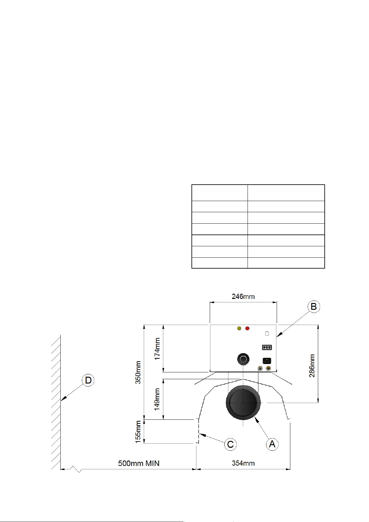
1.3 Heater Suspension
1.3.1 First considerations
• Clearances from combustibles must be
maintained. (See figure 2)
• For ease of servicing there should be a
minimum clearance distance of 500mm
between the burners of the heating system
and the building wall. This measurement
can be reduced for perimeter type systems.
(See figure 1a).
• For ease of servicing and burner removal
minimum clearances should be maintained.
(See figure 1b and 1c). In exceptional
circumstances the burner lid may be slid
diagonally for removal thus reducing the
vertical distance.
• Ensure that the suspension is sufficiently
flexible to allow for thermal expansion.
1.3.2 Suspending the heater - General
1.3.2.1 The first support is always positioned at
the support lug suspension point on the end
vent burner combustion chamber.
1.3.2.2 Subsequent supports are placed
approximately 2.8m apart, including one at each
combustion chamber location. This gives a
maximum load per support of 24kg.
1.3.2.3 A support must always be located at a
maximum distance of 2m from a tee or elbow
fitting.
1.3.2.4 Except for the combustion chamber
support lug suspension points, suspension
support brackets are installed to support the
tube section which is then covered with
reflectors.
1.3.2.5 Tail pipe hangers are installed for the
tube section which will be without reflectors.
If there are any doubts as to the strength or
suitability of roof steelwork to which heaters are
to be suspended, please refer to a Consultant,
Architect or owner of the building.
Table 1. Minimum mounting heights
Model
NRV12LR
NRV18LR
NRV24LR
NRV32LR
NRV38LR
NRV46LR
Minimum Mounting
Heights (m)
3.0m
3.6m
4.0m
4.7m
5.3m
6.0m
Figure 1.a Overall Dimensions
A - Burner Tube
B - LR Burner
C - Optional Perimeter Reflector
D - Wall
(100mm MIN - Perimeter Systems)
4
Page 5
Figure 1.b Clearance for servicing - distances to walls and obstacles above.
G
Figure 1.c Clearance for servicing - distances to obstacles above.
E - Obstacle over burner
F - End vent module
G - Burner lid
E
G
5
Page 6
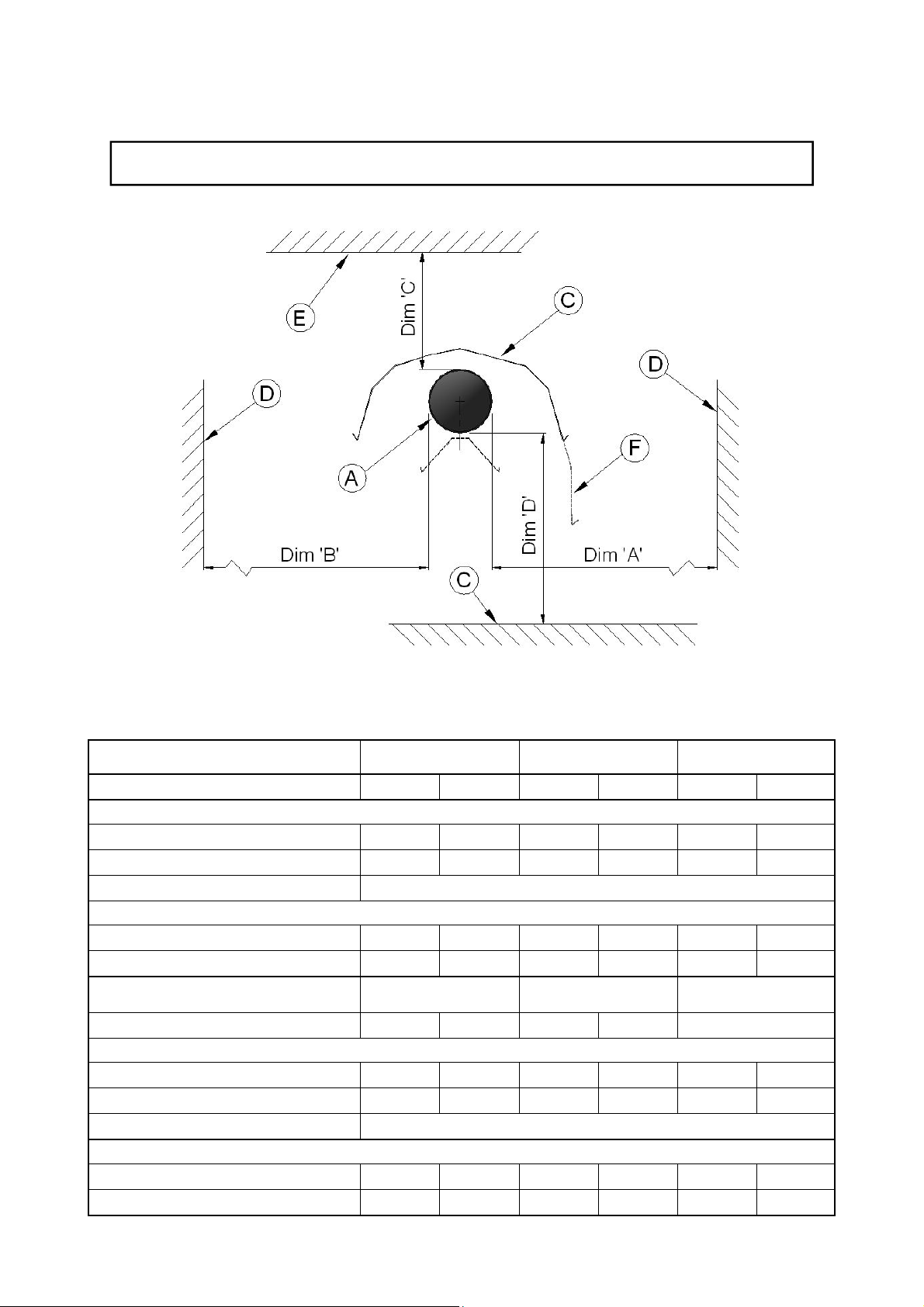
1.4 Clearance to Combustibles.
The minimum clearances to combustible materials are given in table 2 below. These minimum
distances MUST be adhered to at all times.
Figure 2 Diagram illustrating the clearance to combustibles
Distance from combustibles (distance from heat source that will produce a 50ºC rise in temperature above ambient of a
black surface) A Radiant tube; B Standard reflector; C Combustible material underneath; D Combustible material on side;
E Combustible material above; F Perimeter reflector;
Table 2
Burner Model NRV12LR NRV18LR NRV24LR
End vent In-line End vent In-line End vent In-line
Below tube
Dim D
Dim D
Dim C
Horizontally
Dim B
Dim A
Without undershield mm 1120 1250 1120 1250 1120 1250
With undershield mm 760 850 760 850 760 850
Above Tube mm 250
Standard reflector mm 600 770 600 770 600 770
Perimeter reflector mm 305 450 305 450 305 450
Burner Model NRV32LR NRV38LR NRV46LR
End vent In-line End vent In-line End vent
Below tube
Dim D
Dim D
Dim C
Horizontally
Dim B
Dim A
Without undershield mm 1440 1700 1570 2100 1700 2100
With undershield mm 760 850 785 1050 850 1050
Above Tube mm 250
Standard reflector mm 700 850 700 1000 700 1000
Perimeter reflector mm 305 510 305 600 305 600
6
Page 7
1.5 Gas Connection and Supply
Before installation, check that the
local distribution conditions, nature of
gas and pressure, and adjustment of
the appliance are compatible.
A competent or qualified engineer is required to
either install a new gas meter to the service
pipe or to check that the existing meter is
adequate to deal with the rate of gas supply
required.
Installation pipes should be fitted in accordance
with BS 6896, so that the supply pressure, as
stated in Table 3 will be achieved. It is the
responsibility of the competent engineer to
ensure that other relevant Standards and
Codes of Practice are complied with in the
country of installation.
Pipes of smaller size than the heater inlet gas
connection must not be used. The complete
installation must be tested for soundness as
described in the country of installation.
The gas union service cock MUST be
fitted in the gas supply close to the
heater, but not onto the burner itself.
Take care when making a gas connection
to the heater not to apply excessive turning
force to the internal controls.
A flexible hose is installed to allow safe linear
expansion to each burner without creating
undue stress on the gas supply pipe work. It is
therefore important that a tested and certified
hose assembly made to ISO 10380, supplied
with ½” BSP female cone seat adapters, is
installed as per these instructions.
It is also important to ensure that expansion is
taken up in the body of the flexible hose, and
not on its attachment to the pipe work.
The cone seat adapter supplied on one end of
the flexible gas hose provides a `swivel` action,
and must be fitted on the burner using a ½”
BSP barrel nipple to provide ease of
disconnection for future servicing.
The installation layout described below is
the only method recommended by the
institute of gas engineers, the hose
manufacturer, and AmbiRad and must only be
carried out by a qualified/competent gas
engineer.
Table 3 Gas Supply Pressures
Gas Category
Gas Type
Max Supply Pressure (mbar)
Min Supply Pressure (mbar)
Nominal Pressure (mbar)
Gas Supply
G20 G31
Natural Gas Propane
50 57.5
17.5 25
20 37
G25
Natural Gas
50
20
25
G30
Butane
35
20
29
Connection R½ ½in BSP Internal Thread
7
Page 8
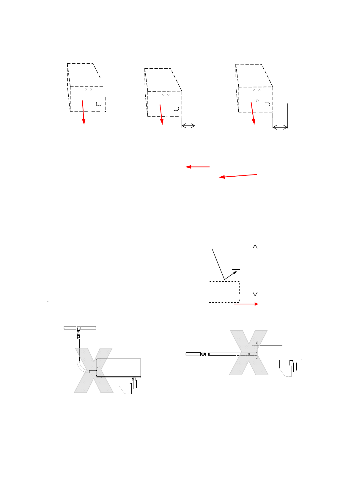
Figure 3. Correct Installation of Flexible Gas Connection
fig.a
fig.b
Depending on the specific installation, the
flexible gas hose may be routed to the gas
cock at any of the following angles in relation to
the burner:
Vertical (fig.a)
45° angle (fig.b)
90° angle (fig.c)
Any other position in between these angles is
acceptable.
Care must be taken to observe the minimum
pipe bend diameter (minimum 250mm,
maximum 350mm) & pipe expansion distance
(minimum 30mm, maximum 70mm) as shown
in fig.e.
Maximum bend diameter for the hose is
450mm.
The correct installation as shown will allow
for approx 100mm of movement due to
expansion.
x
Arrow denotes
direction of
expansion.
fig.d
50 +/- 20mm
Burner
fig.c
x
400 +/- 50mm
fig.e
fig.f
fig.g
The methods shown in fig.f and fig.g are unacceptable, due to undue stress on the hose & fittings.
8
Page 9

1.6 Electrical Connections
Standard burner 16W.
Current rating 0.05 amp per burner
Fuse: external 3 amp.
Each component carrying an electrical
supply must be earthed.
Supply for burners is 230V 50Hz single
phase.
* Exhaust fans are three phase 415V
50Hz.
* IP54 rated Inverter panel LRU’s require
a 230V single phase supply at 22A (B80/
B160) or 30A (B300)
* Standard LRU’s require a 415V three phase
supply at 25A (BH300)
* refer to individual site specifications
All electrical work should be carried out to IEE
standards by a competent electrician.
The electrical connection to the burner is made
by means of a three pin plug-in power
connector. Live, neutral and earth connections
should be made via a flexible supply cable to
the power connector and routed clear of the
heater or tubes.
The flexible supply cables to each burner
should be of 0.5mm²
minimum and comply
with BS 6500:2000. For
fan and LRU supply, the
wire size must be suitable for the current ratings as listed in Table
10.
The wires in the mains
lead are coloured in
accordance with the
following code: Green &
Yellow Earth; Blue
Neutral; Brown Live
The method of connection to the electrical
supply must facilitate complete isolation and
should be via a fused double pole isolator
having contact separation of at least 3mm on all
poles and supplying the appliance only.
We recommend use of AmbiRad approved
controls. Please refer to; SmartCom control
manual for siting and installation details and
figures 4.l and 4.m
Where alternative controls are used, please
refer to the manufactures instructions for their
siting and installation details.
Figure 4.a. Typical Wiring Connections
‘Power out’ from
End Vent Burner to
In-line Burner(s)
End Vent
Burner
To other
in-line burners
Fused Spur
In-line
Burner
Fused Spur
230V 50Hz
Switched Supply
from Control Source
9
Page 10

1.6.1 NRV LR system - Typical External Diagram
Zone 2
Sensor
Screened
Cable
Isolator
SmartCom³ no.2
‘Slave’ (SC3-MZ)
Mains Supply
230V 50Hz 13A
Module
End Vent
End Vent
Fused
0.75mm²
Burner
.
* IMPORTANT
Inverter and Fan is 5m
For Inverter Panels only
(fan types B80/B160 & B300)
MAXIMUM length of cable between
Fused Spur
Burner to In-line Burners
From ‘Power out’ on End Vent
In-line Burner
1st Branch Zone 2
In-line Burner
Fused Spur
Tail Pipe
In-line Burner
Fused Spur
1st Branch Zone 1
Fan types B80/B160 & B300)
MOTOR MUST BE WIRED IN
DELTA.
IMPORTANT
In-line Burner
Fused Spur
* 4 core
Armoured Cable
Isolator
Local Relay
Zone 1
Sensor
0.75mm²
Screened
Cable
Unit / Inverter
Panel
Networking Cable
Screened pair Beldon
Isolator
9841 or equiv
SmartCom³ no.1
‘Master’ (SC3-MZ)
2nd Branch Zone 1
In-line Burner
Fused Spur
From ‘Power out’ on
End Vent Burner to
In-line Burners
10
From ‘Power out’
on End Vent Burner
End Vent
ers
to In-line Burn-
End Vent
Module
End Vent
Module
End Vent
Fused Spur
To ‘Mains In’ on
End Vent Burner
Mains Supply
230V 50Hz 13A
To ‘Mains In’ on
End Vent Burner
Page 11
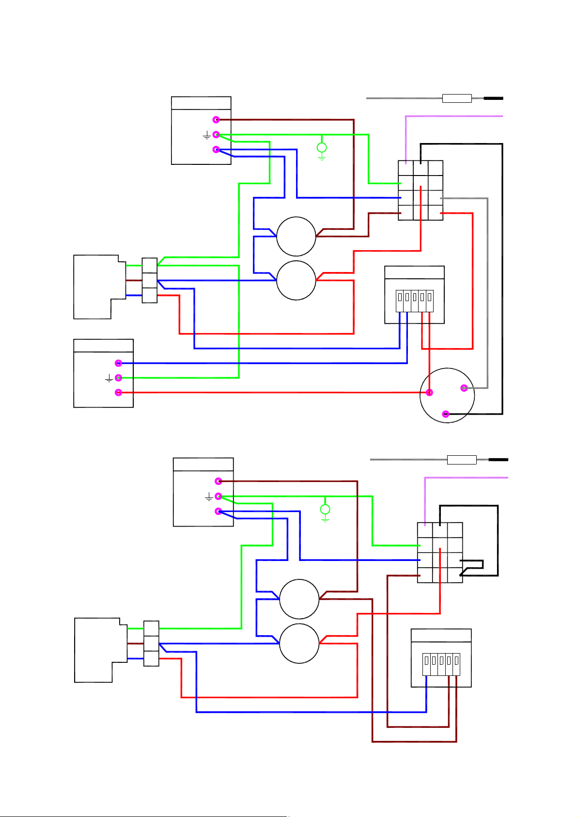
1.6.2 Wiring Details
Figure 4.c. LR internal wiring diagram - End Vent Burner (EV)
SOLENOID
VALVE
POWER OUT
N
L
3
2
1
VALVE
J.S.T.
MAINS INPUT
L
EMC
FILTER
GREEN/YELLOW
N
BLUE
GREEN/YELLOW
BLUE
BLUE
GRN/YEL
LAMPS
MAINS
ON
BURNER
ON
RED
BLUE
BLUE
RED
BLUE
IGNITOR
FLAME SENSOR
BLACK
PURPLE
4
12
8
BROWN
BROWN
7
3
2
1
RED
DELAY TIMER
2345
MAIN
J.S.T.
11
10
9
RED
1
GREY
BLACK
VACUUM
SWITCH
N.O.
C.
N.C.
Figure 4.d. LR internal wiring diagram - In-line Burner (IL)
MAINS INPUT
SOLENOID
VALVE
3
2
1
VALVE
J.S.T.
EMC
FILTER
L
N
GREEN/YELLOW
BLUE
BLUE
GRN/YEL
BLUE
LAMPS
MAINS
ON
BURNER
ON
RED
BLUE
BROWN
BROWN
BROWN
IGNITOR
FLAME SENSOR
PURPLE
4
8
12
7
11
3
2
10
9
1
MAIN
J.S.T.
RED
DELAY TIMER
12345
BLACK
11
Page 12
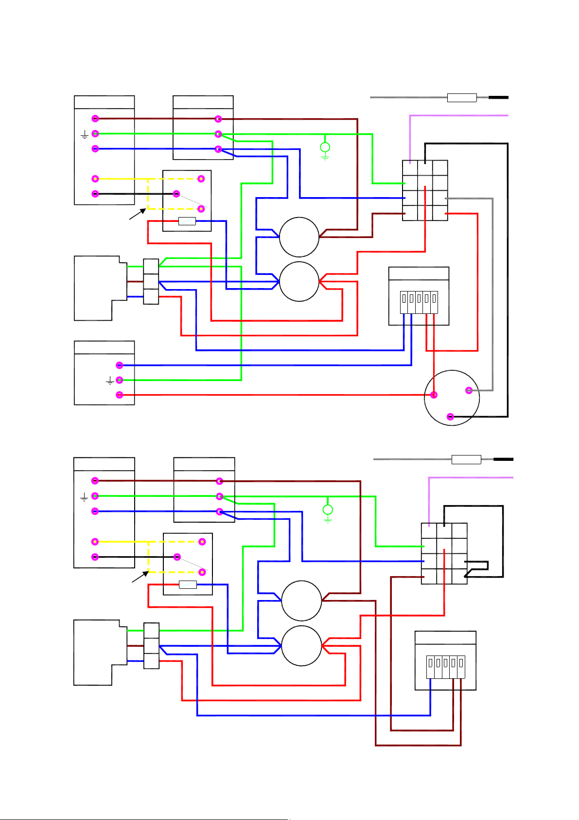
Figure 4.e. LR internal wiring diagram - End Vent Burner c/w N/O or N/C volt free Lockout contacts
MAINS INPUT
L3
N
L2
L1
Detail shows
either N.O. or
N.O. contacts
SOLENOID
VALVE
POWER OUT
N
L
3
2
1
VALVE
J.S.T.
EMC FILTER
RELAY
N.O.
C.
N.C.
A1
A2
BLUE
GREEN/YELLOW
IGNITOR
GRN/YEL
BROWN
BLUE
BLUE
LAMPS
MAINS
GREEN/YELLOW
BLUE
ON
BURNER
BROWN
DELAY TIMER
FLAME SENSOR
BLACK
PURPLE
8
4
12
7
11
3
2
10
9
1
RED
MAIN
J.S.T.
GREY
BLACK
ON
2345
RED
RED
BLUE
BLUE
1
VACUUM
RED
SWITCH
N.O.
C.
N.C.
Figure 4.f. LR internal wiring diagram - In-line Burner c/w N/O or N/C volt free Lockout contacts
MAINS INPUT
L3
N
L2
L1
Detail shows
either N.O. or
N.O. contacts
SOLENOID
VALVE
3
2
1
VALVE
J.S.T.
EMC FILTER
N.O.
C.
N.C.
A1
A2
RELAY
GREEN/YELLOW
BLUE
BLUE
GRN/YEL
LAMPS
MAINS
ON
BURNER
ON
RED
RED
BLUE
BLUE
IGNITOR
FLAME SENSOR
PURPLE
8
4
12
BROWN
7
3
2
11
10
1
9
BLACK
MAIN
J.S.T.
RED
DELAY TIMER
BROWN
BROWN
12345
12
Page 13
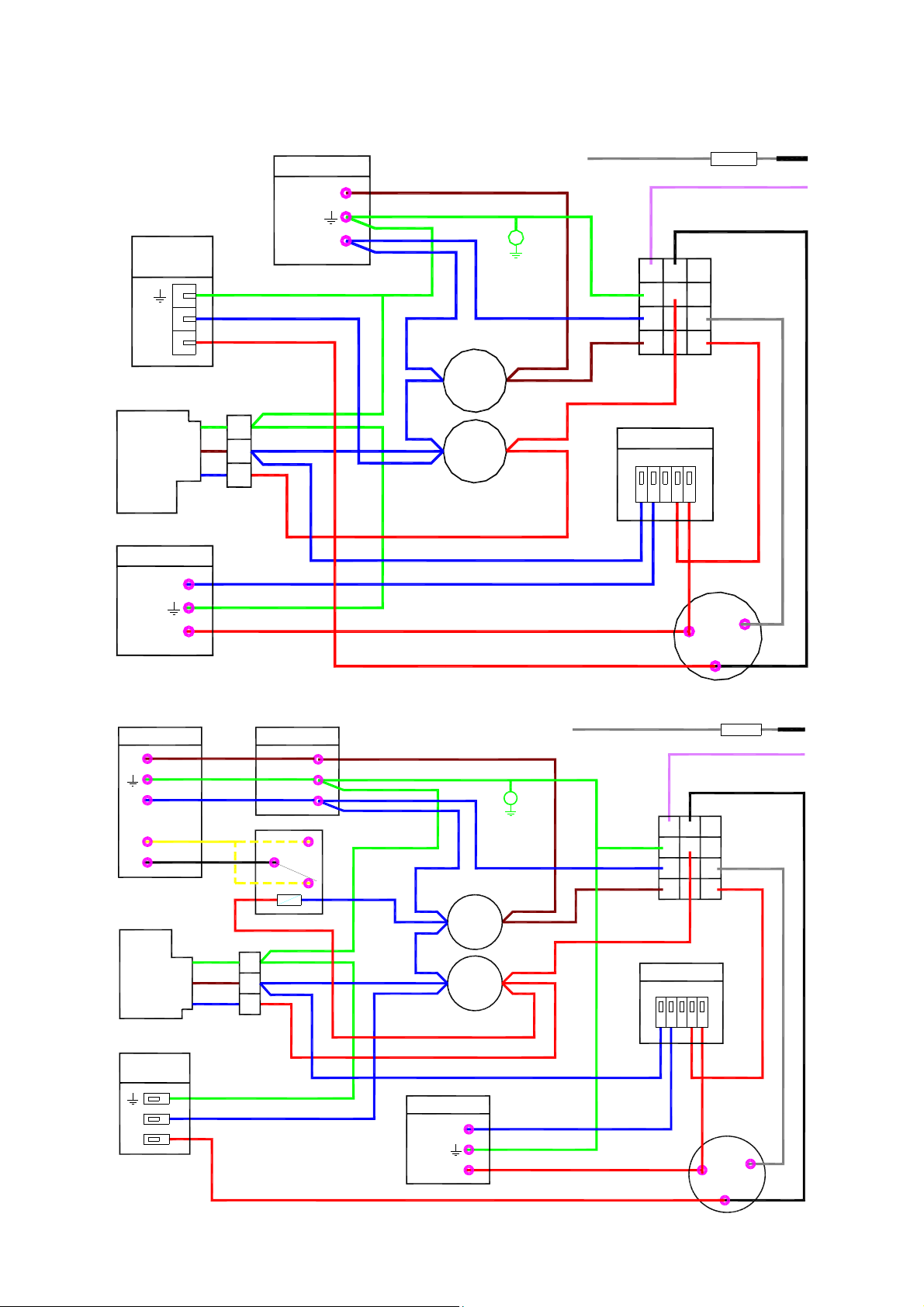
Figure 4.g. LR internal wiring diagram - End Vent Burner c/w 3 way solenoid valve
3 WAY AR
SOLENOID
2
1
SOLENOID
VALVE
POWER OUT
N
L
3
2
1
VALVE
J.S.T.
MAINS INPUT
EMC
FILTER
BLUE
GRN/YEL
L
N
RED
BLUE
IGNITOR
GRN/YEL
BROWN
BLUE
BLUE
LAMPS
MAINS
GREEN/YELLOW
BLUE
ON
BURNER
BROWN
DELAY TIMER
FLAME SENSOR
BLACK
PURPLE
4
8
12
7
11
3
2
10
9
1
RED
MAIN
J.S.T.
RED
BLACK
GREY
ON
2345
1
RED
BLUE
BLUE
VACUUM
RED
RED
SWITCH
N.O.
C.
N.C.
Figure 4.h. LR internal wiring diagram - End Vent Burner c/w valve & N/O or N/C VF Lockout contacts
3
2
1
VALVE
J.S.T.
EMC FILTER
N.O.
C.
N.C.
A1
A2
BLUE
RELAY
GRN/YEL
GRN/YEL
BLUE
LAMPS
MAINS
ON
BLUE
BURNER
RED
RED
BLUE
POWER OUT
N
L
13
ON
BLUE
BLUE
GRN/YEL
RED
RED
IGNITOR
FLAME SENSOR
BLACK
PURPLE
4
8
12
BROWN
BROWN
3
2
1
DELAY TIMER
VACUUM
SWITCH
MAIN
J.S.T.
7
11
10
9
RED
BLACK
GREY
1
2345
N.O.
C.
N.C.
MAINS INPUT
L3
N
L2
L1
SOLENOID
VALVE
3 WAY AR
SOLENOID
2
1
GRN/YEL
BLUE
Page 14
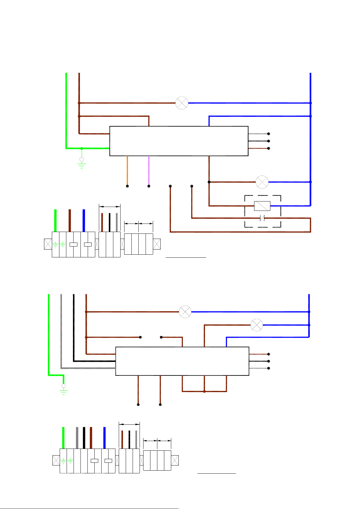
Figure 4.j. NRV Inverter Internal Wiring Diagram for B80, B160 and B300 three phase fans
EL
Green/Yellow
230V 50Hz
1 Ph Supply
LEN
230V 50HZ 1 Pha SUPPLY
Brown
RA
15V LI1
Orange
t1 t2
3Ph Supply
To Fan
Circuit
VF Enable
MAINS ON LAMP
R/L1
Violet
Circuit
Fan Trip
V.S.D.1
AI10V
t3 t4
Brown
Brown
S/L2
RC
Brown
W/T3
V/T2
U/T1
tW
tV
tU
FAN HEALTHY LAMP
A1
A2
11
12
N
Blue
TO FAN
3
4
21
EE
NL NL
VUW
TERMINAL RAIL
Figure 4.k. NRV Local Relay Unit Internal Wiring Diagram for BH300 three phase fans
312
EL
Green/Yellow
Grey
LL
Black
415V 50Hz
3 Ph Supply
321
415V 50HZ 3 Pha SUPPLY
Brown
3
2
1
3Ph Supply
LEN
LL
To Fan
t1 t2
98 97
Brown
t4 t3
Circuit
VF Enable
MAINS ON LAMP
95 A214
Contactor
96 A113
Brown
Circuit
Fan Trip
FAN HEALTHY
6
4
2
tU
TO FAN
tV
tW
N
Blue
EE
3211
LL
4
3
21
NL NL
VUW
14
TERMINAL RAIL
Page 15
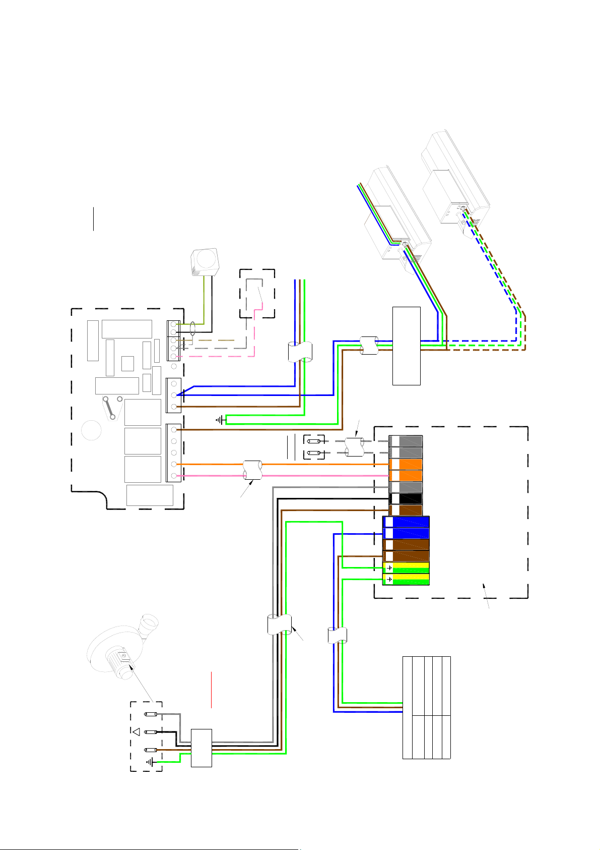
Figure 4.l. NRV Schematic interconnecting wiring. B80, B160 and B300 three phase fans
controlled by SmartCom3 via single phase Inverter panel. (single zone shown)
Zone A
burners
Supply to inline
Burners
frost etc).
therefore all wiring to the control must be
should be connected by 6A mains
enable).
Max length is 100m.
Low voltage switching inputs to be
normally open (closed circuit to
LIVE
Connect to B0 & B1 for remote ON
NOTES:
REMOTE SWITCH INPUTS
NEUT
SmartCom
Singlezone
*The power supply is non-isolated,
Connect to B0 & B2 for remote
OFF (ie door interlock. remote
(ie BMS time control).
B1 B0 B2 S/R0S/R1
6
41 40 9 5 1/L 2/N 10
mains rated.
from the control unit, using
REMOTE SENSOR(s) may be
placed at a max distance of 100m
Black Bulb
(REMOTE OFF)
(COMMON)
(REMOTE ON)
(NEUTRAL)
(LIVE)
(FAN CIRCUIT)
(FAN CIRCUIT)
screened 6A mains* cable.
Sensor
(HEAT 1 OUTPUT)
Wiring should be kept separate
from mains wiring to minimise
functions for remote sensor.
therefore all wiring to the control must be
*The power supply is non-isolated,
mains rated.
noise pick up. Set within Engineers
eg B.M.S.
230V 50Hz 1 Pha
Supply via Isolator
via a 3A fused spur.
Note: Connection to the
burners MUST be made
Volt Free
Circuit
Fan Trip
by others
Indication
Inverter
Unit
Local Relay
Drawing No. : 900287 R4
U V W1 342
+15V DC
Low Voltage
LL NN
230V 3-Phase Supply.
FAN MOTOR
Motor must be wired DELTA
4-Core Armoured or
and fan is 5m (EMC class A building) or
Exhaust
Fan
(fan types B80 / B160 & B300):
MPORTANT
For Inverter panels only
MAXIMUM length of cable between inverter
N.B. if in doubt, do not exceed 5m.
10m (EMC class B building).
Isolator
3 Phase
Screened Cable 1.5mm²
SUPPLY VIA ISOLATOR
230V 1P 22A
ELECTRICAL INPUT
B80
FAN TYPE
S/L2
R/L1
230V 1P 22A
230V 1P 30A
B160
B300
THE LOCAL RELAY UNIT houses an inverter. This
V/T3U/T3 V/T3
three-phase 230V output. The inverter provides a
soft start to the motor, which extends the motor life
converts the 230V single-phase input into a
by minimising the start current.
ESC ENT
15
Page 16
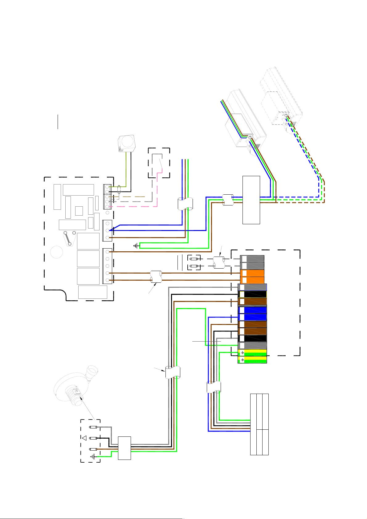
Figure 4.m. NRV Schematic interconnecting wiring. BH300 three phase fans controlled by
SmartCom3 via three phase Local Relay panel. (single zone shown)
Zone A
burners
Supply to inline
Burners
NOTES:
should be connected by 6A mains
REMOTE SWITCH INPUTS
Max length is 100m.
Low voltage switching inputs to be
LIVE
NEUT
SmartCom
Singlezone
enable).
Connect to B0 & B1 for remote ON
normally open (closed circuit to
frost etc).
therefore all wiring to the control must be
*The power supply is non-isolated,
Connect to B0 & B2 for remote
OFF (ie door interlock. remote
(ie BMS time control).
B1 B0 B2 S/R0S/R1
6
41 40 9 5 1/L 2/N 10
from the control unit, using
Wiring should be kept separate
from mains wiring to minimise
functions for remote sensor.
therefore all wiring to the control must be
placed at a max distance of 100m
REMOTE SENSOR(s) may be
(COMMON)
(NEUTRAL)
(LIVE)
Black Bulb
(REMOTE ON)
screened 6A mains* cable.
Sensor
(REMOTE OFF)
(HEAT 1 OUTPUT)
(FAN CIRCUIT)
(FAN CIRCUIT)
mains rated.
*The power supply is non-isolated,
mains rated.
noise pick up. Set within Engineers
eg B.M.S.
230V 50Hz 1 Pha
Supply via Isolator
via a 3A fused spur.
Note: Connection to the
burners MUST be made
Volt Free
Circuit
Fan Trip
Indication
by others
34
2
1
Unit
Local Relay
Drawing No. : 900289 R4
U V W
230V AC
Mains Voltage
NN
L2L3 L1 L1
415V 3-Phase Supply.
FAN MOTOR
Motor must be wired DELTA
4-Core Armoured Cable
Exhaust
Fan
Isolator
3 Phase
415V 3P 25A
ELECTRICAL INPUT
SUPPLY VIA ISOLATOR
BH300
FAN TYPE
16
Page 17
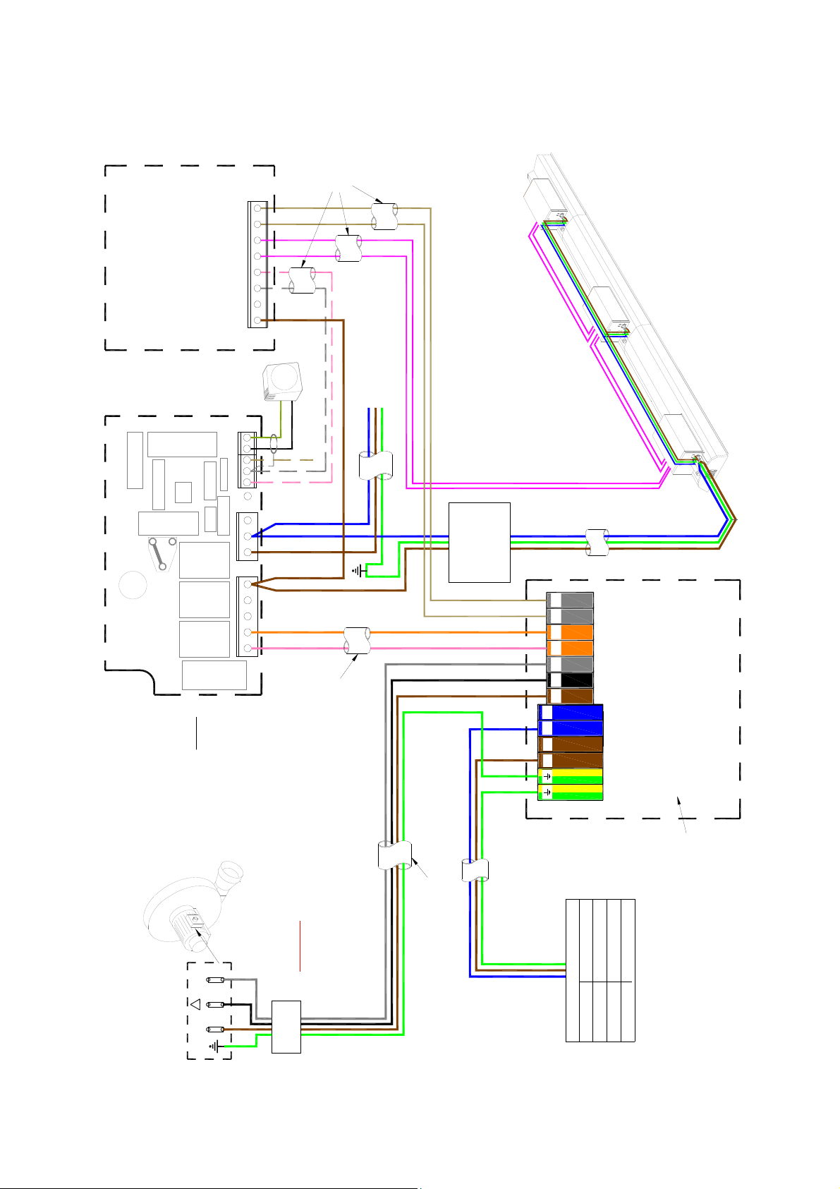
Figure 4.n. NRV Schematic interconnecting wiring. B80, B160 and B300 three phase fans
controlled by SmartCom3 via single phase Inverter panel. Zonal BMS Lockout and VF interface.
Volt
BMS
Volt Free Fan Trip Circuit
Circuit
Volt Free Burner Lockout
Circuit
Volt Free Remote ON
230V VBurner ON Signal
Sensor
Black Bulb
Free
230V 50Hz 1 Pha
Supply via Isolator
Burners
Drawing No. : 900287 R4 LO
Zone A
LIVE
NEUT
SmartCom
Singlezone
230V 3-Phase Supply.
FAN MOTOR
Motor must be wired DELTA
NOTES:
6
41 40 9 5 1/L 2/N 10
B1 B0 B2S/R0S/R1
(REMOTE OFF)
(COMMON)
(REMOTE ON)
(NEUTRAL)
(LIVE)
(HEAT 1 OUTPUT)
(FAN CIRCUIT)
(FAN CIRCUIT)
THE SOFTWARE FOR THE BMS MUST ONLY REQUEST A
Note:
LOCKOUT CONDITION WHEN THE SYSTEM IS
Connection to the
REQUESTING HEAT. IN ADDITION, IT SHOULD ALSO
PROVIDE A 60s DELAY BEFORE INDICATING LOCKOUT.
be made via a
burners MUST
AFTER INITIAL SUPPLY IS CONNECTED TO THE HEATER,
WHEN CALLING FOR THE HEAT VIA THE CONTROL
THIS IS TO ALLOW THE SOLENOID COIL TO OPERATE
3A fused spur.
will receive a false report of the burner status
SYSTEM AND A RE-START ATTEMPT IF NECCESARY
Note: If the point is not complied with the BMS
Inverter
Unit
Local Relay
U V W1 342
+15V DC
Low Voltage
mains rated.
from the control unit, using
screened 6A mains* cable.
functions for remote sensor.
*The power supply is non-isolated,
placed at a max distance of 100m
Wiring should be kept separate
from mains wiring to minimise
therefore all wiring to the control must be
noise pick up. Set within Engineers
REMOTE SENSOR(s) may be
LL NN
Exhaust
Fan
MPORTANT
Isolator
3 Phase
and fan is 5m (EMC class A building) or
(fan types B80 / B160 & B300):
MAXIMUM length of cable between inverter
For Inverter panels only
10m (EMC class B building).
230V 1P 22A
230V 1P 22A
4-Core Armoured or
N.B. if in doubt, do not exceed 5m.
Screened Cable 1.5mm²
SUPPLY VIA ISOLATOR
230V 1P 30A
ELECTRICAL INPUT
B80
B160
B300
FAN TYPE
three-phase 230V output. The inverter provides a
THE LOCAL RELAY UNIT houses an inverter. This
soft start to the motor, which extends the motor life
converts the 230V single-phase input into a
by minimising the start current.
17
Page 18
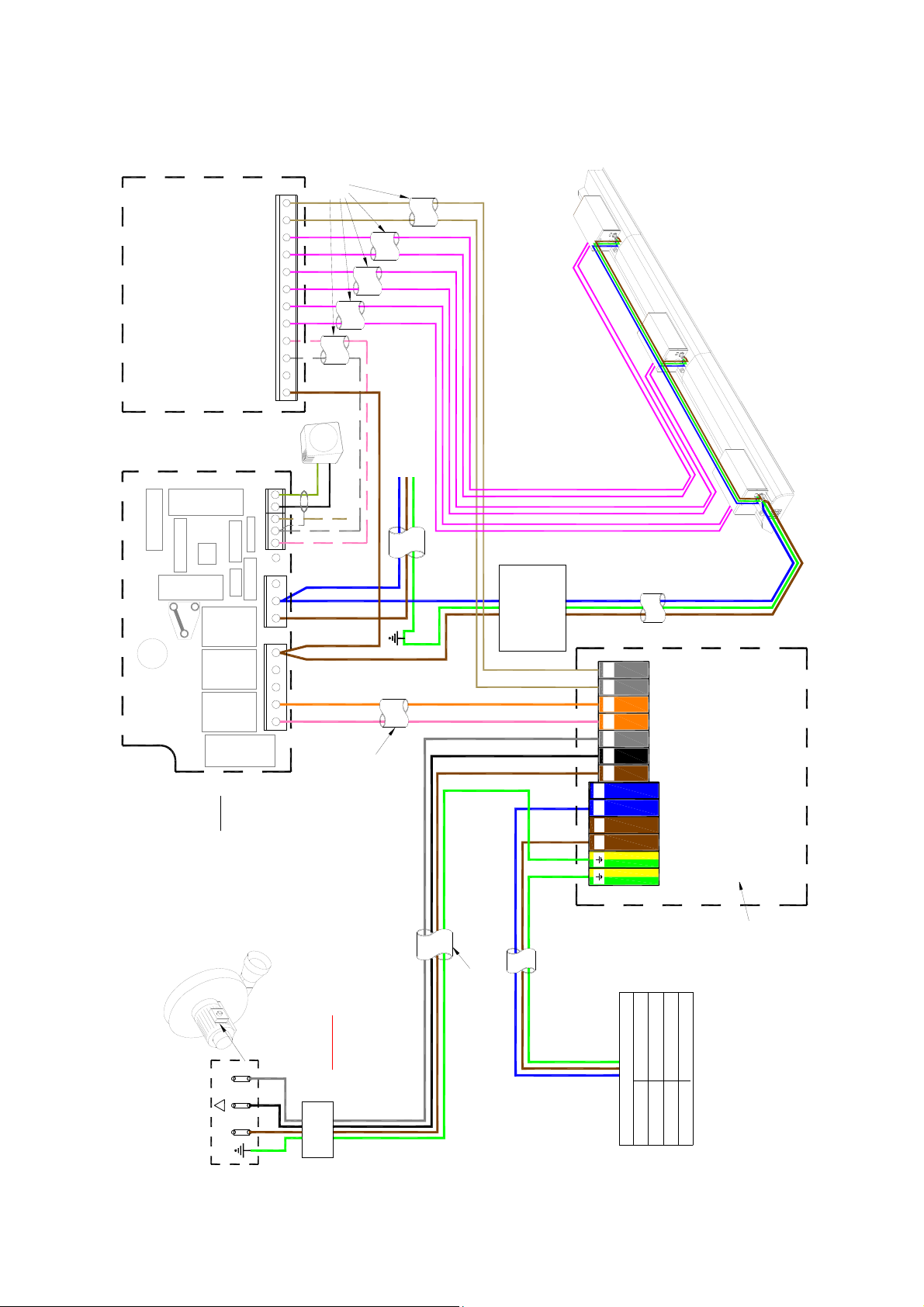
Figure 4.p. NRV Schematic interconnecting wiring. B80, B160 and B300 three phase fans
controlled by SmartCom3 via Inverter panel. Individual BMS burner Lockout and VF interface.
Volt
Volt Free Fan Trip Circuit
Free
BMS
Circuit Burner #3
Volt Free Burner Lockout
Circuit Burner #2
Volt Free Burner Lockout
Circuit Burner #1
Volt Free Burner Lockout
Circuit
Volt Free Remote ON
Drawing No. : 900287 R4 LOM
Zone A
Burners
230V VBurner ON Signal
Sensor
Black Bulb
(REMOTE OFF)
(COMMON)
B1 B0 B2S/R0S/R1
LIVE
NEUT
6
(REMOTE ON)
(NEUTRAL)
(LIVE)
230V 50Hz 1 Pha
Supply via Isolator
THE SOFTWARE FOR THE BMS MUST ONLY REQUEST A LOCKOUT
CONDITION WHEN THE SYSTEM IS REQUESTING HEAT. IN ADDITION,
LOCKOUT. THIS IS TO ALLOW THE SOLENOID COIL TO OPERATE
IT SHOULD ALSO PROVIDE A 60s DELAY BEFORE INDICATING
AFTER INITIAL SUPPLY IS CONNECTED TO THE HEATER, WHEN
the BMS will receive a false
CALLING FOR THE HEAT VIA THE CONTROL SYSTEM AND A
report of the burner status.
RE-START ATTEMPT IF NECCESARY.
Note: If the point is not complied with
Note:
be made via a
3A fused spur.
burners MUST
Connection to the
(HEAT 1 OUTPUT)
SmartCom
230V 3-Phase Supply.
FAN MOTOR
Exhaust
Singlezone
Motor must be wired DELTA
Fan
(FAN CIRCUIT)
41 40 9 5 1/L 2/N 10
(FAN CIRCUIT)
Inverter
Local Relay
Unit
U V W1 342
+15V DC
Low Voltage
NOTES:
from the control unit, using
screened 6A mains* cable.
placed at a max distance of 100m
from mains wiring to minimise
Wiring should be kept separate
REMOTE SENSOR(s) may be
noise pick up. Set within Engineers
functions for remote sensor.
*The power supply is non-isolated,
3 Phase
mains rated.
therefore all wiring to the control must be
MPORTANT
For Inverter panels only
Isolator
and fan is 5m (EMC class A building) or
(fan types B80 / B160 & B300):
MAXIMUM length of cable between inverter
10m (EMC class B building).
4-Core Armoured or
N.B. if in doubt, do not exceed 5m.
Screened Cable 1.5mm²
LL NN
230V 1P 22A
230V 1P 22A
230V 1P 30A
ELECTRICAL INPUT
SUPPLY VIA ISOLATOR
B80
B160
B300
FAN TYPE
THE LOCAL RELAY UNIT houses an inverter. This
three-phase 230V output. The inverter provides a
soft start to the motor, which extends the motor life
converts the 230V single-phase input into a
by minimising the start current.
18
Page 19

1.7 Ventilation Requirements
Nor-Ray-Vac heaters are installed as flued
appliances in accordance with the relevant
national requirements i n the country of
installation.
In buildings having an air change rate of less
than 0.5 per hour, additional ventilation is
required. For detailed information, please see
BS6896 section 5.2.2.2.1
Natural Ventilation
Low level ventilation openings with a free area
of at least 2cm²/kW shall be provided. See
BS6896 section 5.2.2.2.2.1.
1.8 Exhaust and Air Inlet - Options
1.8.1 Horizontal discharge
1.8.2 Vertical discharge
19
Considerations.
The vacuum fan must be located as
shown in the layout drawing.
The vacuum fan must have a bottom
horizontal discharge.
The fan should be fitted to the mounting
platform which is fixed to the wall or
building structure. Alternatively, the fan
can be suspended from the roof
structure, via drop rods (not supplied) and
mounted on base frame. (Anti-vibration
mountings are fitted between the fan and
the mounting platform/base frame.
For full details of parts and installation,
please refer to section 2.9.3
Page 20
1.8.3 Ducted Air Inlet Considerations.
Heat resistant flexible tube is connected to the
burner assembly ducted air adaptor and the
EVM ducted air adaptor and connected to the
air supply duct
The maximum length of 100mm diameter
ductwork is 2m.
Ensure that the flexible supply duct does not
drape over or touch the reflector.
Figure 5.a. Header Duct Connection
Main header Duct
Ø150 for LR12-24
Ø200 for LR32-46
Ensure that the flexible ductwork is installed to
allow for expansion of the heating system.
On a header duct, the main air supply header
which is feeding the individual branch ducts and
burner/end vent supply ducts must have a
maximum pressure drop of 0.25 mbar (0.1in
wg).
All joints and seams in the air supply system
must be made air tight and a bird screen used at
the inlet.
For full details refer to section 2.13
Branch Duct
Ø100 for LR12-24, Ø150 for LR32-46
Ø100 Duct to burner
Ø100 Duct to EVM
500mm MIN
450mm MIN
(For heater duct
Directly above system)
Figure 5.b.
End Vent Ducted
Air Inlet Connection
Figure 5.c.
Burner Ducted
Air Inlet Connection
20
Page 21

1.9 Vacuum fan mounting details (Type ‘B160’ fan illustrated)
A (crs)
B
C
D
E (Ø)
F
G (Ø)
H
J
K
L
M
N
P
Fan Size B80 B160 B300 BH300
216 276 286 324
595 595 625 704
305 308 330 352
580 555 575 650
150 152 152 152
50 97 50 50
150 150 150 148
295 318 340 380
80 90 90 110
150 140 140 120
240 240 240 240
309 303 341 404
50 62 157 157
421 463 616 680
R (crs)
S (crs)
T
V
X
318 318 318 318
356 356 356 356
204 204 204 204
115 115 115 115
21 36 46 84
21
Page 22
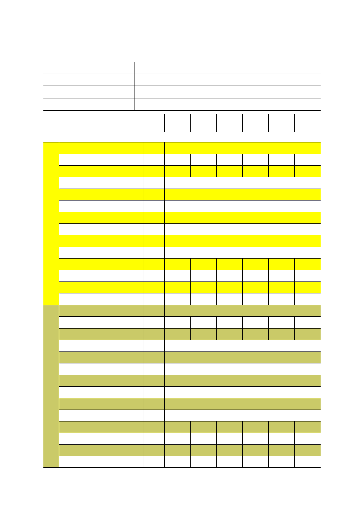
1.10 Technical Details.
Tables 4a & b Burner Details
No of Injectors
1
Gas Connection
Burner current
Electrical Voltage/Ph/Hz
½ in BSP Internal thread
0.05 (per burner)
230 volt 1 phase 50Hz
Burner Type 12LR 18LR 24LR 32LR 38LR 46LR
Burner Details
Gas Category II
Heat input (Gross) kW 12 18 24 32 38 46
Gas consum rate Nat Gas G20 m³/h 1.14 1.72 2.29 3.05 3.62 4.38
Max Inlet pressure Nat Gas G20 mbar 50
G20 Natural Gas
Min Inlet Pressure Nat Gas G20 mbar 17.5
Hs Nat Gas G20 MJ/m³ 37.78
Hi Nat Gas G20 MJ/m³ 34.02
d Nat Gas G20 0.555
Ws Nat Gas G20 MJ/m³ 50.72
Wi Nat Gas G20 MJ/m³ 45.67
Injector size Nat Gas G20 mm 3.6 4.4 4.9 5.4 5.8 6.3
Injector Part No. L100336 L100544 L100549 L100554 L100558 L100563
Air shutter size Nat Gas G20 mm 13 17 19.5 22.0 24.0 26.5
Air shutter Part No. L100322 L100321 L100320 L100314 L100316 L100318
Gas Category II
Heat input (Gross) kW 12 18 24 32 38 46
Gas consum rate Nat Gas G25 m³/h 1.33 1.99 2.66 3.55 4.21 5.10
Max Inlet pressure Nat Gas G25 mbar 50
G25 Natural Gas
Min Inlet Pressure Nat Gas G25 mbar 20
Hs Nat Gas G25 MJ/m³ 32.49
Hi Nat Gas G25 MJ/m³ 29.25
d Nat Gas G25 0.612
Ws Nat Gas G25 MJ/m³ 41.52
Wi Nat Gas G25 MJ/m³ 37.38
Injector size Nat Gas G25 mm 3.7 4.6 5.2 5.8 6.3 6.9
Injector Part No. L100537 L100546 L100552 L100558 L100563 L100569
Air shutter size Nat Gas G25 mm 13 17 19.5 22.0 24.0 26.5
Air shutter Part No. L100322 L100321 L100320 L100314 L100316 L100318
22
Page 23
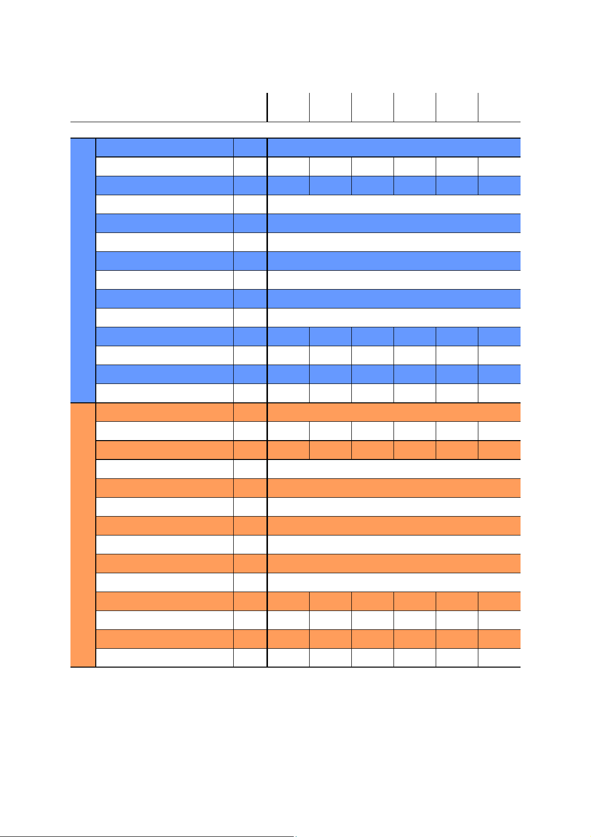
Tables 4c & d Burner Details
Burner Type 12LR 18LR 24LR 32LR 38LR 46LR
Burner Details
Gas Category III
Heat input (Gross) kW 12 18 24 32 38 46
Gas consum rate Butane G30 m³/h 0.34 0.52 0.69 0.92 1.09 1.32
Max Inlet pressure Butane G30 mbar 35
G30 Butane Gas
Min Inlet Pressure Butane G30 mbar 20
Hs Butane G30 MJ/m³ 125.81
Hi Butane G30 MJ/m³ 116.09
d Butane G30 2.075
Ws Butane G30 MJ/m³ 87.33
Wi Butane G30 MJ/m³ 80.58
Injector size Butane G30 mm 2.6 3.2 3.7 4.2 4.6 5.1
Injector Part No. L100526 L100532 L100537 L100542 L100546 L100551
Air shutter size Butane G30 mm 13 17 19.5 22.0 24.0 26.5
Air shutter Part No. L100322 L100321 L100320 L100314 L100316 L100318
Gas Category III
Heat input (Gross) kW 12 18 24 32 38 46
Gas consum rate Propane G31 m³/h 0.45 0.68 0.90 1.21 1.43 1.73
Max Inlet pressure Propane G31 mbar 57.5
G31 Propane Gas
Min Inlet Pressure Propane G31 mbar 25
Hs Propane G31 MJ/m³ 95.65
Hi Propane G31 MJ/m³ 88.00
d Propane G31 1.55
Ws Propane G31 MJ/m³ 76.84
Wi Propane G31 MJ/m³ 70.69
Injector size Propane G31 mm 2.9 3.5 4.0 4.4 4.8 5.2
Injector Part No. L100529 L100535 L100540 L100544 L100548 L100552
Air shutter size Propane G31 mm 13 17 19.5 22.0 24.0 26.5
Air shutter Part No. L100322 L100321 L100320 L100314 L100316 L100318
Hs = Gross CV
Hi = Net CV
Ws = Wobble number on gross CV
Wi = Wobble number on net CV
d = specific density
Reference gas conditions = dry, 15ºC 1013 mbar
23
Page 24
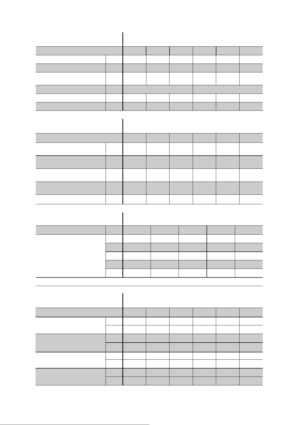
Table 5. Heater Details
Burner Type
Min distance between burners m 5.2 7.4 9.4 14 18 23
Max distance between burners m 7.2 10.2 13.1 18 23 27
Min distance between burner
and fitting
Max tube temp °C 450 480
Min mounting height m 3.0 3.6 4.0 4.7 5.3 6.0
Max burners per branch 5 4 3 3 3 3
m 3.6 3.6 5.0 6.0 7.0 8.0
Table 6. End Vent Module (EVM)
Burner Type
End vent setting (hot)
- Multi burner systems
End vent setting (hot)
- SINGLE End Vent burners only
End vent setting (hot)
- THREE burners in a branch
End Vent orifice diameter mm 14.5 16 24 27 32 n/a
mbar
mbar n/a n/a n/a 7.5 8.25 9.25
mbar n/a n/a n/a n/a n/a 5.6
12LR 18LR 24LR 32LR 38LR 46LR
12LR 18LR 24LR 32LR 38LR 46LR
6.25 6.25 6.25 6.25 6.25 6.25
End Vent orifice Part No. L104102 L104101 L104100 L104093 L104092 n/a
Table 7.
Burner Dip-switch position
(see section 3.3.1.8)
Burner Number
(within each radiant branch lowest number closest to fan)
To set dip-switch slide the white switch toward the numbers (1-4)
Table 8. Noise Data
Burner Type
Noise level @ 3m below
In-Line BURNER
Noise level @ 3m below
EVM Burner
1 1 1 1 1 1
2 - 2 2 2 1
3 - - 3 3 2
4 - - - 4 3
5 - - - - 4
db(A) 46 47 47 48 50 51
NR±2 40 41 41 42 44 45
db(A) 46 48 48 52 55 58
NR±2 40 42 42 46 49 52
1 2 3 4 5
12LR 18LR 24LR 32LR 38LR 46LR
Number (qty) of burners in-line
Noise level @ 3m below
EVM with silencer
Noise level @ 3m below
EVM Burner with Ducted Air
db(A) 44 45 45 48 51 53
NR±2 38 39 39 42 45 47
db(A) tba tba tba tba tba tba
NR±2 tba tba tba tba tba tba
24
Page 25
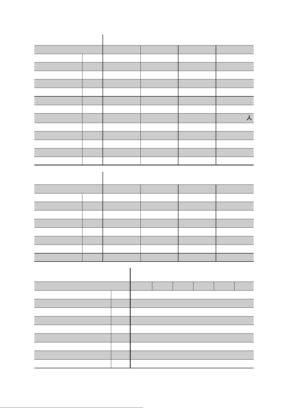
Table 9. Fan Details
Fan Size
Fan part number
Motor (TEE)
Power kW 1.1 1.5 2.2 4.0
Supply to Fan V/Hz/P 230~50/3 230~50/3 230~50/3 400~50/3
Run Current A 4.38 5.6 8.48 7.2
Start Current A n/a n/a n/a 54.0
Speed RPM 2850 2860 2480 2880
Wired
Flow rate @ 20°C m³/h 368 736 1380 1380
Flow rate @ 150°C m³/h 259 519 972 972
Pressure mbar 29 29 29 42
Max Operating Temp. °C 200 200 200 200
Weight kg 45 52 58 75
QS 80M2B H QS 90S2A-40H QS 90L2A H QS 112M2A H
Table 10. Local Relay Unit
Fan Size B80 B160 B300 BH300
B80 B160 B300 BH300
201760 201761 201732 201763
∆ ∆ ∆
LRU part number
Inverter type kW 1.5 1.5 2.2 n/a
Supply to LRU V/Hz/P 230~50/1 230~50/1 230~50/1 400~50/3
Line Current A 14.8 14.8 20.8 n/a
Motor Current A 4.2 5.6 7.8 7.2
Fuse Rating A 22 22 30 n/a
Acceleration Time s 25 25 25 n/a
Deceleration Time s 25 25 25 n/a
Table 11. System Weights
LR Burner kg 8.3
Radiant branch* kg/m 8.3
Radiant branch + Slimline grille* kg/m 10.9
Radiant branch + Protective guard* kg/m 10.0
4” Mild steel tail pipe kg/m 5.5
4” Aluminum tail pipe kg/m 0.9
Burner Type
900274 900088 900089 900282
12LR 18LR 24LR 32LR 38LR 46LR
6” Mild steel tail pipe kg/m 10.6
6” Aluminium tail pipe kg/m 1.3
Max / susp point @ EV position kg 24.2
* without burners or ducted air systems
25
Page 26
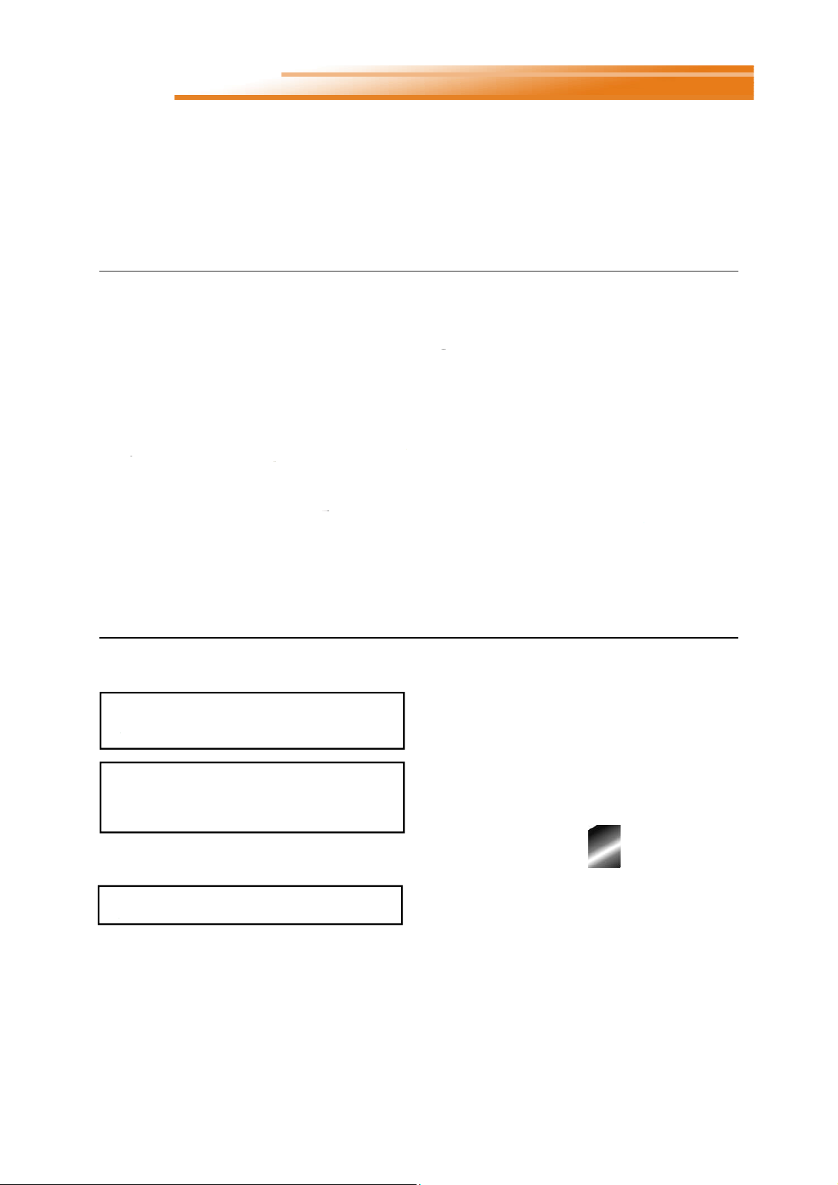
2. Assembly Instructions.
PLEASE READ this section prior to
assembly to familiarise yourself with the
components and tools you require at the
various stages of assembly. Carefully open the
packaging and check the contents against the
parts and check list.
The manufacturer reserves the right to alter
specifications without prior notice.
2.1 Tools Required.
The following tools and equipment are advisable
to complete the tasks laid out in this manual.
Trestles
Wrench With
Extension
Leather
Faced
Gloves
13mm
Socket
Please ensure that all packaging is
disposed of in a safe environmentally
friendly way.
For your own safety we recommend the
use of safety boots and leather faced
gloves when handling sharp or heavy items. The
use of protective eye wear is also
recommended.
Suitable alternative tools may be used.
Pozidrive
Screwdriver
Tape
Measure
10mm,
12mm &
13mm
Spanners
4 & 5mm
Allen
Keys
Saw
2.2 Assembly Notes.
Please read these assembly notes in
conjunction with the correct assembly
drawings (Sections 2.2.1 to 2.21.1)
The system is assembled at high level
suspended by chains from first fixings to
the roof structure.
(First fixings by others)
2.2.1 Radiant Tubes
Note: on assembly, tube seams to be
facing upwards.
All radiant tubes are
101mm (4”) O/D, ERW
steel to BS 6323:Part 5:
are factory pre-painted
and supplied in 5.2m
lengths.
These may need to be
cut depending on the system drawing design.
Pop
Riveter
& 3/16”
Rivets
Silicone
Sealant
& Gun
Burner Combustion
Chamber
Combustion chambers are
2.6m in length and increase in
diameter to 127mm (5”) around the
burner turret.
All tubing, combustion chambers, dampers and
tube fittings are connected by ‘wrap-around’
stainless steel couplers which clamp by means
of two high tensile stainless steel set pins. (See
section 2.2.2)
26
Page 27

2.2.2 Couplers
The Nor-Ray-Vac Tube Coupler is a screw
tightening, self aligning - positive located tubular
coupler. Manufactured in a non–corrosive
stainless steel it is available in both 100mm (4”)
and 150mm (6”).
Two high tensile stainless steel set pins tighten
to clamp the coupler onto the tube whilst a rivet
provides a centralised permanent stop to give
the joint equidistance.
The following procedure explains the correct
method of assembly:
Before assembly, carefully loosen the two
screws. Position the coupler onto the first tube
ensuring that the bars are positioned uppermost.
Slide the second tube into the coupler ensuring
that the rivet stop has butted up to the tube end.
Using the 6mm allen key, tighten the second
pin. DO NOT OVERTIGHTEN.
Slide the coupler over the tube ensuring that the
rivet stop has butted up to the tube end.
Using a 6mm allen key, tighten the relevant pin.
DO NOT OVERTIGHTEN.
Moving between the two set pins, tighten both
ensuring that equal pressure is applied to each
set pin in turn.
If all steps have been followed correctly, the
coupler should have aligned itself parallel to the
two tubes and a slight indentation can be
observed. Using the 6mm allen key, finally
tighten each screw by a further quarter turn. If a
power tool is used, use a torque limit setting of
6.6 lbf/ft (0.91kgf/m) must be achieved.
27
Page 28
2.2.3 Reflectors
The radiant tube sections of the system are
fitted with reflectors made of either stainless
steel or aludip to direct infra-red rays
downwards.
The reflectors have a unique design profile to
maximise the reflected radiant heat, minimise
convective loss, and maximise on rigidity.
The reflectors are overlapped and held in
position by the reflector bracket assembly.
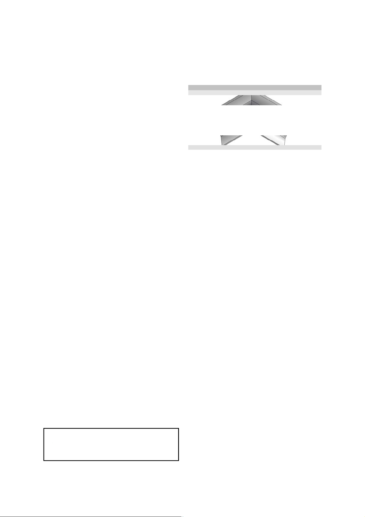
2.2.3.3 Corner Reflectors
Used where radiant tubes are joined with a 90°
bend. The corner reflector comes in two pieces
and is assembled on-site.
Corner Reflector
There are two styles of reflectors:
2.2.3.1 Standard Reflectors
These 2.4m long reflectors are positioned above
the tube to radiate the heat downwards and are
fixed to the radiant tube via a reflector bracket
(see section 2.5). The combustion chamber
reflector has a rectangular hole and slot, pre cut
to allow for burner combustion chamber and
support lug fitting.
2.2.3.4 Tee piece Reflectors
Used where a radiant tube connects to another
at right angles. The reflector is a special short
section with a central tube cut out.
Tee section
Combustion Chamber
Reflector
2.2.3.2 Perimeter Reflectors
Perimeter reflectors are used when the radiant
tube is mounted at the perimeter of the building.
They have the same profile as standard
reflectors but extended one side to direct the
radiant heat away from the wall.
The perimeter combustion chamber reflectors
have a cut-out for the combustion chamber
turret and suspension lug at both ends so that
the one reflector can be used for either left or
right hand perimeter systems.
2.2.4 Brackets
There are two styles of brackets:
2.2.4.1 Suspension brackets.
Suspension brackets are made from a one
piece construction and are formed to support
the tube and reflector alike. The wrap around
ends are aligned to hold a turnbuckle eyelet in
the correct hanging position.
Note: when overlapping the perimeter
combustion chamber reflector, extra
overlap is required to cover the pre-cut
holes and slot.
Standard
Suspension Bracket
28
Page 29
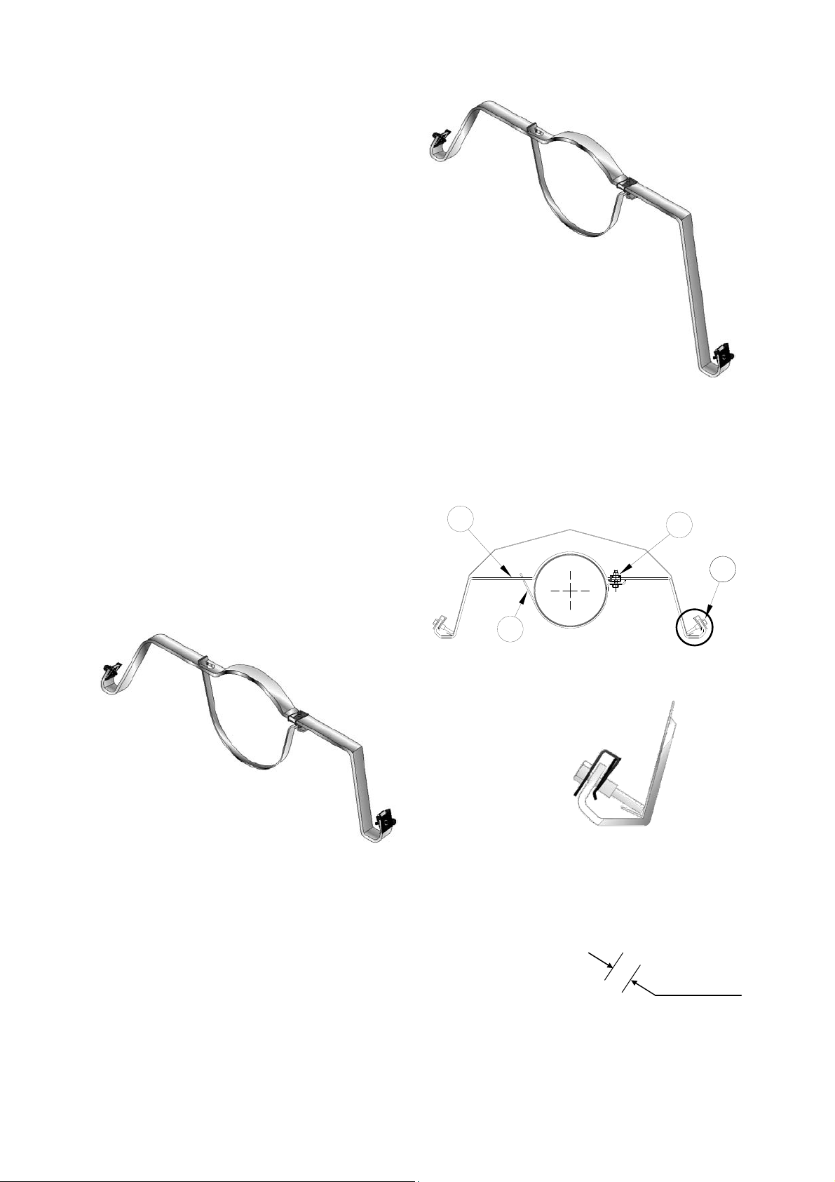
A perimeter suspension bracket is available
which has the same profile as the standard
brackets but extended one side to
accommodate the perimeter reflector.
Perimeter Reflector
Support Bracket
2.2.4.2.1 Attachment of reflector
bracket.
Primeter
Suspension Bracket
2.2.4.2 Reflector Support Bracket
Reflector Support Brackets are a two piece
construction. The first half is formed to seat on
top of the radiant tube and supports the reflector
sides in position. The second part clamps
around the bottom half of the tube and is fixed in
position via a fastener.
Fit the reflector bracket (B) around the
tube and tighten the set pin (D) to clamp the
central clip (C) to the tube.
The set pins (A) positioned at both edges of the
bracket (B) are used to provide either a fixed
joint or a sliding joint.
B
D
A
C
Fully tighten these screws for fixed joints.
‘Fixed Joint’ detail.
Standard Reflector
Support Bracket
Leave a minimum 3mm gap clearance between
The reflector support bracket has two functions
depending on the position of the fixing screws.
1. To fix the reflector into position.
2. To allow the reflector to slide within the
bracket for thermal expansion.
A perimeter reflector support bracket is available
which has the same profile as the standard
brackets but extended one side to
accommodate the perimeter reflector.
reflector and screws for a sliding joint.
‘Sliding Joint’ detail.
The reflector overlap after each burner must be
a ‘sliding joint’, to allow for thermal expansion.
min 3mm GAP
29
Page 30

The next downstream reflector overlap must be
a ‘fixed joint’.
This pattern of alternate sliding and fixed joints
will continue up to the next in line burner or
damper assembly.
A reflector support bracket must be positioned at
the end vent and at the damper end of each
radiant branch, plus either side of a reflector
corner and reflector tee section.
These units must be ‘fixed joints’.
2.2.5 Burner
2.2.5.1 LR Burner Unit
Each burner will consist of:
The ignition and flame
sensing electrode
assembly is mounted to
the casting flange of the
burner face.
2.2.6 End Vent Module (EVM)
At the start of each radiant branch an end vent
module is connected to the rear of the first
combustion chamber. The end vent module
externally maintains the lines of the reflector
profile.
A burner control housing (BCH) of chassis style
with detachable pivoting lid. All control wiring to
the burner head is within the BCH, which also
contains a combination gas valve comprising of
2 class 2 solenoid valves, dedicated zero
governor and filter, a full sequence controller
and cassette air filter for primary air supply to
the burner. Externally on the BCH, neon lights
indicate mains on and burner on modes.
The air and gas are pre-mixed to stoichiometric
proportions within the burner head assembly,
prior to being admitte d to the point of
combustion.
Ignition is by an electric arc forward of the face
of the burner head on to the main frame.
To comply with European standards that state
air flow must be proven in each radiant branch,
the end vent burner incorporates an air pressure
switch. The end vent module incorporates the
flow sensing pipework carrier air orifice plate
and optional silencer box to reduce noise levels.
2.2.7 Vacuum fans
A low noise robust steel plate fabricated
centrifugal fan coated with heat and corrosion
resistant paint, capable of a static pressure of
either 29 mbar or 45 mbar at 20°C and directly
coupled to a totally enclosed motor to be fitted
at the end of the tube system.
The fan exhausts the products of combustion
LR Burner
from the system discharging through an outlet
flue pipe to atmosphere
external to the building.
2.2.5.2 Burner Head
A burner head assembly of lightweight cast
aluminium construction, a ceramic style burner
head insert, maintained in position by the flame
The maximum operating
temperature is 200°C.
The fan motor is IP55
rated for external use.
retention grid. The casting assembly also
accommodates the gas jet, air shutter and
mixing chamber.
LR Burner head
End Vent Module
Exhaust Fan
30
Page 31

m
m
0
0
8
2
D
2.3 Installation of End Vent Section.
connect the speedlink (C) to the turnbuckle (D).
speedlink (C) through the eye of the suspension lug (B), and then
2.3.3 Suspend the end vent combustion chamber (A) by locating the
vent burner combustion chamber (A).
2.3.2 The first support is positioned at the suspension lug (B) on the end
chamber turret and lug (B)
2.3.1 locate the cut out of the combustion chamber reflector (N) over the combustion
N
C
28
00
m
m
B
max load per support of 24kg.
approximately 2.8m apart, This gives a
2.3.4 Subsequent supports (E) are placed
m
m
00
8
2
C
D
G
E
F
E
D
C
31
A
G
2.3.5 Except for the combustion chamber
suspension lug (B), suspension support
brackets (E) are installed to support the
tube section which is then covered with
reflectors.
the end vent towards the fan.
A. Combustion Chamber - L101020-SUB; B. Suspension Lug; C. Speedlink - 6524; D. Turnbuckle -
C766300-SUB; E. Suspension Hanger - C110500-SUB (perimeter - C110501-SUB); F. Radiant Tube
2.3.6 Connect a length of radiant tube (F) to the end vent combustion
chamber (A) by use of couplings (G), ensuring it is supported by the suspension
support brackets (E).
NOTES: 1. The radiant tube should be installed with the seam weld facing upwards.
2. Ensure the radiant tube is installed in the horizontal or with a slight fall away from
Ø100 - 1040; G. Tube Coupler - C112110 (Ø100); N. Combustion Chamber Reflector - L105050.
Page 32

H
or elbow (H) fitting.
be located at a maximum
distance of 2m from a tee
2.3.12 A support (E) must
G
E
m
m
0
0
8
2
C
D
F
2.3.10 Connect a length of radiant tube (F) to the
end vent combustion chamber (A) by use of couplings
(G), ensuring it is supported by the suspension support
brackets (E).
E
weld facing upwards.
NOTES: 1. The radiant tube should be installed with the seam
with a slight fall away from the end vent towards the fan.
N
2. Ensure the radiant tube is installed in the horizontal or
2.3.11 Subsequent supports (E) are placed approximately 2.8m apart. This
gives a max load per support of 24kg.
A. Combustion Chamber - L101020-SUB; B. Suspension Lug; C. Speedlink - 65 24;
D. Turnbuckle - C766300-SUB; E. Suspension Hanger - C110500-SUB (perimeter -
C110501-SUB); F. Radiant Tube Ø100 - 1040; G. Tube Coupler - C112110 (Ø100),
H. 90° Bend - C112108 (black Ø100); N. Combustion Chamber Reflector -
L105050.
mm
0
0
8
2
G
B
A
C
D
2.3.8 Suspend the in-line combustion
chamber (A) by locating the
speedlink (C) through the
eye of the suspension lug
2.3.7 locate the cut out of the in-line
combustion chamber reflector (N) over
the in-line combustion chamber turret
and lug.
Installation of Radiant Tube (In-line Section)
(B), and then connect
the speedlink (C) to the
turnbuckle (D).
32
2.3.9 Except for the in-line
combustion chamber suspension
lug (B), suspension support brackets (E)
are installed to support the tube section
which is then covered with reflectors.
G
F
Page 33

m
m
0
0
8
2
C
D
L
2.4 Installation of Radiant tube to Tail Pipe
K
K
G
J
H
2.4.3 Connect
G
the radiant tube
section to the tail pipe
section (L) by use of a tube
G
increaser (J) and couplings (G), as
per the layout drawing.
I
G
D
H
2.4.2 Dampers (I) must be
located as indicated in the layout
drawing. The adjustment lever
must be positioned to one side
to allow clear access for
C
setting.
G
K
C
mm
0
0
8
2
D
C
D
M
K
Note: The final 12m of tail
pipe prior to the vacuum fan is
2.4.1 Tail pipe hangers (K) slung from turnbuckl es
(D) and Speedlinks (C) are installed to hang
the manifold and tail pipe section
which will be without
aluminium (M). All tube couplers on
M
this section ONLY must be sealed with a bead of
silicone sealant on each side of the coupler.
NO SEALANT ON ANY BLACK TUBE!!
Note: Ensure the tail pipe section has the correct fall
reflectors.
G
33
(25mm in every 6m towards the fan).
C. Speedlink - 6524; D. Turnbuckle - C766300-SUB; E. Suspension Hanger - C110500-SUB; G. Tube Coupler - C11 2110 (Ø100),
C112120 (Ø150); H. 90° Bend - C112108 (black Ø100), C112109 (black Ø150), L101554 (Alu m Ø150); I. Damper - C110241-SUB;
J. Increaser - C112117; K. Ø150 Tail Pipe Hanger - C112015; L. Ø150 Black Tail Pipe - C112126; M. Ø150 Alum Tail Pipe - 7230-3.
Page 34

2.5 Installation of Main Reflectors
2.5.4 The third reflector bracket (P3) is installed 100mm
from the end of the first plain reflector (O1). 2.5.5 Slide the second plain reflector (O2) through the
second downstream suspension support bracket (E2), then
over the first plain reflector (O1) and into the third reflector
bracket (P3). Ensure that the reflector overlap is a
E1
complete.
until the radiant branch is
brackets where required
additional reflectors / support
E2
2.5.6 Continue this sequence, installing
minimum of 225mm.
E
P4
O2
P3
A
P1
O1
P2
2.5.3 Slide the first plain reflector (O1) through the first
downstream suspension support bracket (E1), then under
the combustion chamber reflector (N) and into the second
reflector bracket (P2). Ensure that the reflector overlap is a
minimum of 225mm.
34
2.5.1 Install the first reflector bracket
(P1) behind the turret of the combustion
chamber (A). 2.5.2 Install the second reflector bracket (P2)
100mm from the other end of the combustion
chamber reflector (N).
A. Combustion Chamber - L101020-SUB; E. Suspension Hanger - C110500-SUB; O. Plain Reflector - L1050 24;
P. Reflector Support Bracket - L201008-SUB;
Page 35
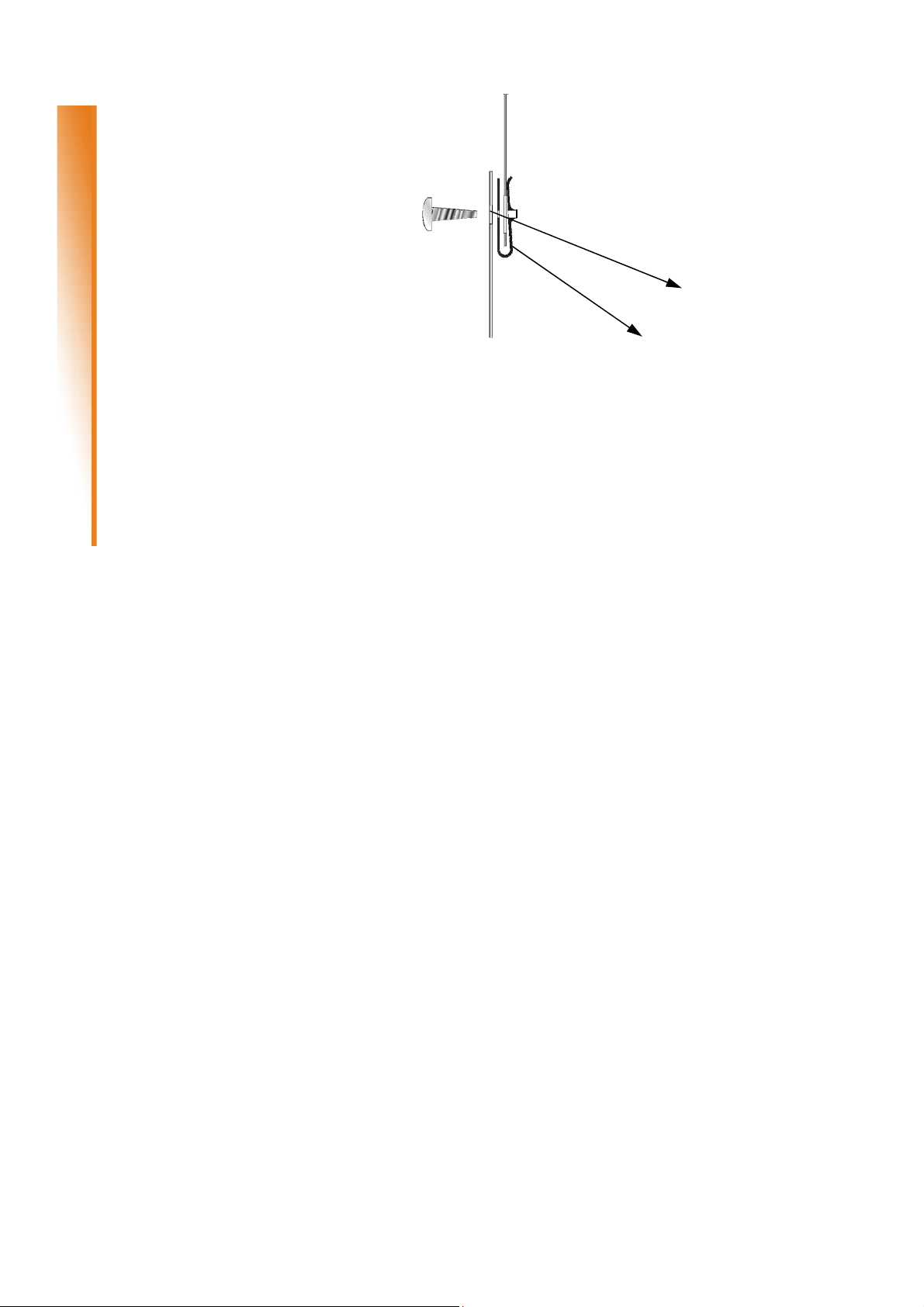
2.6 Installation of Corner Reflectors
O
E
P
O1
P
Q
Q
2.6.1 The corner section must first be assembled by overlapping the right hand reflector (Q1) over the
tabbed left hand reflector (Q2) and secured using a No. 8 self tapping screws into a capture nut placed on
the flange of the reflector (Q2). nb Ensure that the two reflector overlaps are 225mm.
E
35
P
plain reflector (O1) will need to be used by cutting down a standard length. NOTE: this is the only
2.6.2 Position a reflector support bracket (P) at the centre of each reflector overlap. 2.6.3 If a bend connects directly with the rear of an in-line combustion chamber, a short section of
situation where a reflector is cut short, in all other situations increase of the overlap will be necessary.
A. Combustion Chamber - L101020-SUB; E. Suspension Hanger - C110500-S UB; O. Plain Reflector - L105024; P. Reflector Support Bracket - L201008-S UB;
Q. Corner Reflector Assembly - L105009-SUB
Page 36
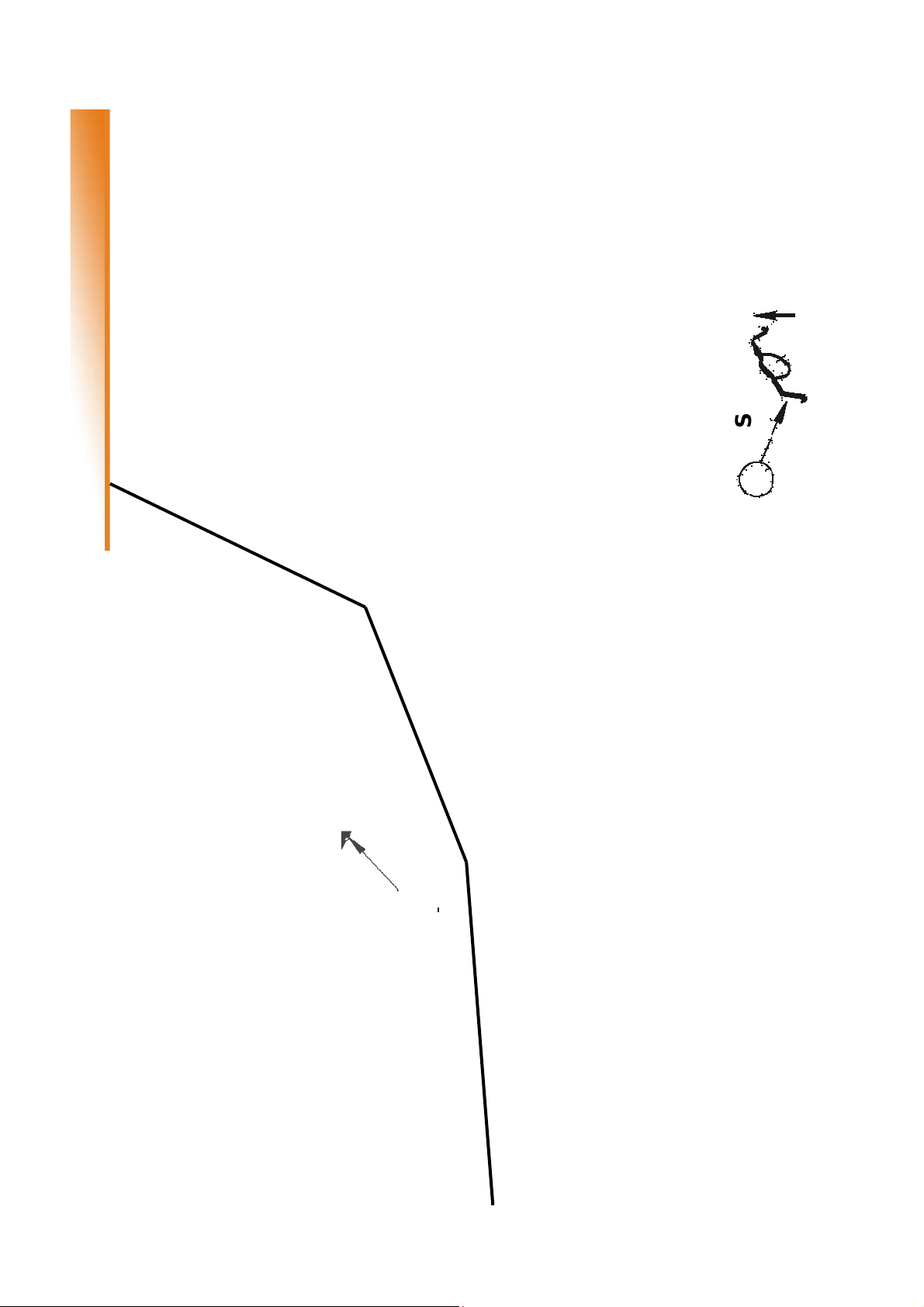
2.7 Installation of Tee Reflectors
C
D
R
O
E
P
C
I
E
D
S
G
P
225mm
P
P
G
P
O
C
D
E
n.b. Ensure that the reflector
overlaps are a minimum of
225mm.
m
m
5
2
2
36
2.7.1 Position the reflector with side
cut-out over the ends of the two plain
reflectors. 2.7.2 Position a reflector support
bracket (P) at the centre of each
reflector overlap and 100mm
from end of last plain reflector
in radiant branch. 2.7.3 At the entry to the tee
section, the plain reflector (O)
MUST be fitted with a reflector
end cap (S).
C. Speedlink - 6524; D. Turnbuckle - C766300-SUB; E. Suspension Hanger - C110500-SUB; G. T ube Coupler - C112110 (Ø100), C1 12120 (Ø150); I. Damper - C1102 41-SUB;
O. Plain Reflector - L105024; P. Reflector Support Bracket - L201008-SUB; R. Reflector with Side cut out - L105026; S. End Cap - L105043;
Page 37

P
P
S
2.8 Final Fixtures and Adjustment
Thus, the overlap of the perimeter combustion chamber reflector with the
second perimeter reflector must be such that the cut-outs are adequately
covered ie. 1000mm overlap.
L
m
m
5
2
2
P
m
m
5
2
2
P
m
m
5
2
2
P
m
systems.
m
5
2
2
2.8.1 General. Ensure all reflector overlaps are a minimum of 225mm and that
there is a reflector support bracket positioned in the centre of the overlap. 2.8.2 End Caps. At the end of each reflected radiant branch the last reflector
must have an end cap (S) fitted. 2.8.2.1 Using the end cap (S) as a template mark the positions of the two fixing
holes onto the last reflector. Drill two 5mm diameter holes through the positions
marked. 2.8.2.2 Position the end cap (S) under the last reflector and secure using the two
M4 set-screws provided. 2.8.3 Perimeter reflectors (Not shown) Perimeter reflectors are used when the
or right hand perimeter
P
can be used for either left
ends so that the one reflector
turret and suspension lug at both
m
m
5
2
2
a cut-out for the combustion chamber
perimeter combustion chamber reflectors have
P
the perimeter combustion chamber reflectors. The
procedure is the same as above, with the exception of
reflector bracket assemblies are provided and the assembly
m
m
5
2
2
Special perimeter suspension support brackets and perimeter
P
P
wall.
37
L. Ø150 Mild Steel Tail Pipe - C112126;
P. Reflector Support Bracket - L201008-SUB; S. End Cap - L105043;
radiant tube is mounted at the perimeter of the building. They are standard 2.4m
long reflectors but with one side extended to direct the radiant heat away from the
Page 38

2.9 Installation of Fan Exhaust System
using a turnbuckle (D) which is connected to the eye
bolt by a speedlink (C).
2.9.1.5 The condensate trap assembly (V) is connected
to the 150mm diameter fan inlet connection via coupler
(G).
Zb
2.9.1 Fan exhaust duct for vertical discharge
2.9.1.1 In vertical discharge, a tee piece (W) must be fitted in the
exhaust ducting with a connection to drain.
Flue couplers (G) are used to connect all exhaust flue fittings. All ducting must be sealed using silicone sealant to avoid condensate
K1
leaking to the outside of the ductwork. Ensure that an adequate weatherproof seal such as a ’dektite’ is
G
made where the duct passes through the roof. The flue terminal (Zb) is fitted by first applying silicone sealant around
Za
the connecting tube ends and then inserting the swaged end of the
flue terminal into the 150mm diameter flue duct. The joint is secured
by drilling through the tube and connector with 3 pop rivets at 12, 4
and 8 o’clock position. 3.5 mm (3/16 in) diameter pop rivets are
recommended. (Not supplied by AmbiRad).
G
D
U
T
U
W
K
2.9.1.3 The system aluminium tail pipe (M) is connected via an ex-
pansion joint (T) to the 150 mm condensate trap assembly (V) and
secured by jubilee clips (U) at each end. A gap of approximately 150mm must be maintained between the
G
condensate trap assembly (V) and the tail pipe (M).
T
D
C
2.9.1.4 The condensate trap assembly (V) must be supported
U
Xa
M
U
Xb
V
Y
C. Speedlink - 6524; D. Turnbuckle - C766300-SUB;
E. Suspension Hanger - C110500-SUB; G. Tube
Coupler - C112120 (Ø150); M. Ø150 Alum Tail Pipe -
7230-3; T. Expansion Joint - 7532; U. Jubilee Clip Ø150
- 7542; V. Condensate Trap Assembly - L101527-SUB;
W. Tee Piece Ø150 - M201024; Xa. Fan Wall Mounting
Platform - L103060; Xb. (alternate) Fan Base Frame;
Y. Fan - refer table.9; Za. Ø150 Flue Pipe (1m lengths)
- A791050; Zb. Flue Terminal - L101580-SUB
2.9.1.2 The vacuum fan (Y) must be located as
shown in the layout drawing and must have a bottom
horizontal discharge. The fan can be fitted to the mounting
38
platform (Xa) which is fixed to the wall or
building structure. Alternatively, the fan
can be suspended
from the roof
structure, via drop
rods (not supplied)
and mounted on
base frame (Xb).
Page 39

Installation of Fan Exhaust System cont.
connect all exhaust duct fittings.
from the fan to avoid condensate running back
into the fan. Flue couplers (G) are used to
sealant to avoid condensate leaking to the
ends and then inserting the swaged end of the
flue terminal into the 150mm diameter flue duct.
The joint is secured by drilling through the tube and
connector with 3 pop rivets at 12, 4 and 8 o’clock
position. 3.5 mm (3/16 in) diameter pop rivets are
recommended. (Not supplied by AmbiRad).
assembly (V) and the tail pipe (M).
maintained between the condensate trap
A gap of approximately 150mm must be
jubilee clips (U) at each end.
condensate trap assembly (V) and secured by
nected via an expansion joint (T) to the 150 mm
2.9.2.3 The system aluminium tail pipe (M) is con-
The condensate trap assembly (V) must be
The flue terminal (Zb) is fitted by first applying
silicone sealant around the connecting tube
building wall.
sleeve (a - not supplied by AmbiRad) must be
fitted between the exhaust flue duct and the
outside of the ductwork. A non-combustible
All flue ducting must be sealed using silicone
Zb
a
M
2.9.2 Fan exhaust duct for horizontal discharge
2.9.2.1 The exhaust flue duct (Za) must incline downwards away
D
U
T
U
Y
G
Za
K
G
C
T
D
Xa
V
U
Xb
supported using a turnbuckle (D) which is connected to the
U
eye bolt by a speedlink (C). The condensate trap assembly (V) is connected to the
150mm diameter fan inlet connection via coupler (G).
2.9.2.2 The vacuum fan (Y) must be located as
shown in the layout drawing and must
have a bottom horizontal discharge. The fan can be fitted to the
mounting platform (Xa) which is
fixed to the wall or building
structure. Alternatively, the
fan can be suspended
from the roof structure,
via drop rods (not
supplied) and mounted
on base frame (Xb).
39
C. Speedlink - 6524; D. Turnbuckle - C766300-SUB; E. Suspension Hange r - C110500-S UB;
G. Tube Coupler - C112120 (Ø150); M. Ø150 Alum Tail Pipe - 7230-3; T. Expansion J oint -
7532; U. Jubilee Clip Ø150 - 7542; V. Condensate Trap Assembly - L101527-SUB;
Xa. Fan Wall Mounting Platform - L103060; Xb. (alternate) Fan Base Frame; Y. Fan - refer
table.9; Za. Ø150 Flue Pipe (1m lengths) - A791050; Zb. Flue Terminal - L101580-SUB
Page 40

Installation of Fan Exhaust System cont.
Y
X1
X2
X3
X4
Xb
2.9.3.1 The vacuum fan (Y) must be located as shown in the layout drawing and must have a bottom
2.9.3 Fan Mounting
X1
Y
horizontal discharge.
structure. Mounting holes are pre drilled on the vertical legs of the platform.
The fan should be fitted to a mounting platform (X) which is fixed to the wall or building
X2
Locate the mounting stool of the fan into position on the platform (Xa). Ensure
X3
anti-vibration mountings are used and secure in position.
Anti-vibration mountings are supplied as a kit of parts (X1 - X5).
2.9.3.2 Alternatively, the fan can be suspended
from a roof structure, via drop (not supplied)
and mounted on base frame (Xb). Locate the mounting stool of the fan
into position on the frame (Xb). Ensure anti-vibration mountings
are used and secure in
position. X5 not used with
base frame.
Xa
X5
X4
X2
40
Xa. Fan Wall Mounting Platform - L103060; Xb. (alternate) Fan Base Frame;
X1-5 Anti-vibration Mount Kit - L103045-SUB; Y. Fan - refer table.9;
Page 41

Installation of Fan Exhaust System cont.
during commissioning, is adjusted by
rotating handle (V5) then locking with grub
screw.
Damper to control the vacuum of the system
V2
If the drainage pipe has a run externally, it is recommended that the pipe
is insulated to protect against frost.
avoid freezing.
Any external pipework should be kept to a minimum to
Any internal pipework should be of a diameter stated.
pipe to a drain might be subject to local building controls.
It should be noted that the connection of a condensate
rainwater system or a purpose-made soakway.
Alternatively, the condensate can be discharged into the
internally to a soil and vent stack or a waste pipe.
Preferably the condensate pipe should run and terminate
V3
V1
V4
See note*
V5
V
2.9.4 Condensate Trap Assembly
The condensate trap assembly (V) is connected to the 150mm diameter fan
inlet connection via a coupler. Ensure that a 1½ in (38 mm) drain tube assembly is fitted to the connection
(V1) and to the non-return valve
(V3) via bends (V2). Ensure that the non-return valve
(V3 - supplied) is fitted with the
flow indication arrow pointing
AWAY from the trap, in the
V. Condensate Trap Assembly - L101527-SUB; V1 - Tube Connector; V2. Drain Tube; V3. Non-return Valve; V4. Drain Tube; V5. Damper Handle
HORIZONTAL position and at a
vertical distance of 670mm* for BH
type fans or 520mm* for B type
fans, below the condensate trap assembly. The condensate drainage pipe (V4 - not
supplied) should be run in a standard drain
41
pipe material, e.g. polyvinyl chloride (PVC),
unplasticized polyvinyl chloride (PVC-U),
ancrylonitrile-butadiene-styrene (ABS),
polypropylene polyproene (PP) or cross-linked
polyviynyl chloride (PVC-C).
Copper or copper based alloy shall not be used for
condensate drains. See BS 6896.
The drain tube must be resistant against the action
of flue gas condensate and suitable for operation
up to a maximum temperature of 50°C. Ensure that the drain tube is adequately supported. All connecting drainage pipework should have a fall
of at least 2.5° to the horizontal or approximately 50mm per metre of pipe
run.
Page 42

H
28
C
2.10 Full Breakdown of Typical System
D
m
D
G
G
C
G
E
F
D
E
m
G
m
0
0
28
D
A
J
D
C
L
K
I
m
m
0
0
28
m
m
0
0
K
G
H
G
K
M
D
m
0
0
28
C
K
C
B
G
H
C
D
U
Zb
T
U
a
K
G
H
D
D
G
C
C
28
m
m
0
0
D
E
E
T
D
C
Za
G
V
U
U
28
m
m
0
0
D
F
X
C
m
m
0
Y
0
28
B
E
G
A
F. Radiant Tube Ø100 - 1040; G. Tube Coupler - C112110 (Ø100), C112120 (Ø150); H. 90° Bend - C112108 (black Ø100), C112109 (black Ø150),
L101554 (Alum Ø150); I. Damper - C110241-SUB; J. Increaser - C112117; K. Ø150 Tail Pipe Hanger - C112015; L. Ø150 Black Tail Pipe - C112126;
M. Ø150 Alum Tail Pipe - 7230-3; T. Expansion Joint - 7532; U. Jubilee Clip Ø150 - 7542; V. Condensate Trap Assembly - L1015 27-SUB; W. Tee Piece Ø150 -
D
A. Combustion Chamber - L101020-SUB; B. Suspension Lug; C. Speedlink - 6524; D. Turnbuckle - C766300-SUB; E. Suspension Hanger - C110500-SUB;
M201024; X. Fan Mounting Platform - L103060; Y. Fan - refer table.9; Za. Ø150 Flue Pipe (1m lengths) - A791050; Zb. Flue Terminal - L101580-SUB
C
42
Page 43

AB
AC
In-line Burner
A
2.11 Installation of End Vent and In Line Burners
2.11.3 Position heat shield (AD) on top of gasket (AC) in line with all four
fixing holes of gasket and turret. 2.11.4 Fit each burner through heat shield (AD), gasket (AC) and turret.
Square burner in line with all four fixing holes of gasket and turret.
2.11.5 Secure the burner through the heat shield (AD) and gasket (AC) to
the turret using the four M6 bolts (AE) and washers (AF) provided.
2.11.6 Repeat for all other end
vent and inline burners
AF
AE
AE
AF
AD
AC
A
End Vent Burner
AA
AD
43
2.11.1 Each burner is marked with its rated heat input, “EV” denotes end
vent burner (AA), “IL” denotes inline burner (AB). The correct burner
MUST be located as indicated on the site layout drawing. If the difference between the two types is still unclear, the end vent
burner has a pressure switch fitted inside and has two air pipe connectors
located in the bottom right hand corner when looking at the rear of the
AA. End Vent Burner; AB. IL Burner; AC. Burner Gasket - L102032; AD. Burner Heat Shield - 200195; AE. 6mm Set Pin - 5429-1; AF. 6mm Washer - 5425
unit. 2.11.2 Position gasket (AC) on combustion chamber turret (A), in line
with all four fixing holes.
Page 44

2
AK
2.12 Installation of End Vent Module
2.12.3 Ensure combustion chamber tube end butts positively against the
orifice plate.
Secure using the M8 set pin (AH). 2.12.4 With the EVM (AG) in position on the end of the combustion
chamber: a attach the ‘U’ shaped bundy piece (AJ) to the compression fitting
labelled ‘1’ b attach the ‘L’ shaped bundy piece (AK) to the compression fitting
labelled ‘2’, positioned at the rear of the end vent burner (AA).
1
AJ
Ensure fittings are tightened securely.
AA
AG
44
AH
2.12.1 An end vent module or ‘EVM’ (AG) is positioned at each end vent
burner position. Each end vent module must be fitted with the correct end vent orifice
plate to suit the end vent burner. An orifice or orifice plate attached inside the EVM support spinning is
located on the air entry point of the EVM.
2.12.2 Slide the EVM support spinning over the end vent combustion
chamber tube.
AA. End Vent Burner; AG. End Vent Module; AH. M8 Set Pin - 5447; AJ. Air Tube 1 - L104053; AK. Air Tube 2 - L104054; 1. Compression fitting # 1; 2. Compression Fitting # 2
Page 45

2.13 Installation of Ducted Air Adaptors
AU
AR
AP
AS
AQ
AM
AN
AT
AV *
place inside the housing lid (A) via
The primary air filter (AM) will remain in
2.13.2 Fitting ducted air adaptor to end vent module
The ducted air adaptor (AP) is fitted to the air inlet position of the EVM.
To achieve this, the EVM has to be taken apart. Remove the EVM.
the same screws.
2.13.2.1Unscrew the fasteners (AS) securing the EVM outer plate (AQ)
and remove. 2.13.2.2 Position ducted air adaptor against inlet plate and secure using
four M5 set screws (AT) washers and Nuts (AU) provided.
2.13.2.3 Reposition assembled plate onto the EVM inner plate (AR) and
affix using screws (AS)
* Optional 90° elbow (AV) can be fitted to allow individual orientation.
AL
2.13.1 Fitting ducted air adaptor to burner assembly The ducted air adaptor (AL) is fitted over the air inlet position of the
45
burner housing lid using two M5x30 set-screws (AN).
Ducted Air Lid
AL. Burner Ducted Air Adaptor - L104115; AM. Filter - L102013; AN. M5x30 Set screw; AP. EVM Ducted Air Adaptor - L104122-SUB; AQ. EVM Outer Plate;
AR. EVM Inner Plate; AS. EVM Fastener; AT. M5 Set Pin - 5369; AU. M5 Nut - 5350; AV. 90° Elbow - 7075-2
Page 46

2.14 Installation of Ball Guard System
BG
2.14.2 Blanking Shields
It may be necessary to prevent heat
being directly emitted from certain points
BE
along the radiated tube. Blanking plates
are available for use with ballguards in
400mm sections, which prohibit this.
BD
BH
BF
BA
nb. Reflectors removed for clarity
m
m
0
0
1
BD
2.14.2.1 Place the blanking plate
(BG) inside the ball guard (BA) to
cover the area concerned.
Align two retaining plates
(BD) on the underside of the
guard. Fasten together using
M8x25 pins (BH), M8 nuts
(BE) and washers (BF) prior
to fixing the ball guard as
BE
above.
BF
1
m
m
0
0
1
1
BC
BE
The Nor-Ray-Vac ballguard system consists of standard 2.44m long modules which are supported from the underside of
the radiant tube. The ballguard sections are fitted in tandem along the system. Perimeter ballguards are installed in the
same manor. 2.14.1 Installation 2.14.1.1 Starting at each system end vent, position the ‘U’ bolts (BB) around the radiant tube, through the clamp bridge
(BC) and secure using with M8 nuts (BE).
Ensure that the distance between the ‘U’ bolts is approximately 1100mm.
The ‘U’ bolt assemblies should be positioned perfectly square to ensure that the
ballguard module lies horizontal when fitted. 2.14.1.2 A retaining plate (BD) is positioned on the underside of
the ballguard (BA) at each ‘U’ bolt assembly position and
secured using M8 nuts (BE) and washers (BF). 2.14.1.3 It is necessary to cut the edge of the
ballguard section (BA) at the interface
with the suspension support bracket.
If necessary a standard 2.44m
46
long ballguard can be
shortened by the
I n s t a l l a t i o n
engineer.
BB
BA. 2.44M Ballguard - C110555; BB. ’U’ Bolt - C110548; BC. Clamp Bridge - C110549; BD. Clamp Pla te - C110449; BE. M8 Nut - 5441; BF. M8 Washer - 54 45;
BG. Blanking Shield - L106020; BH. M8 x 25 Set Pin
Page 47
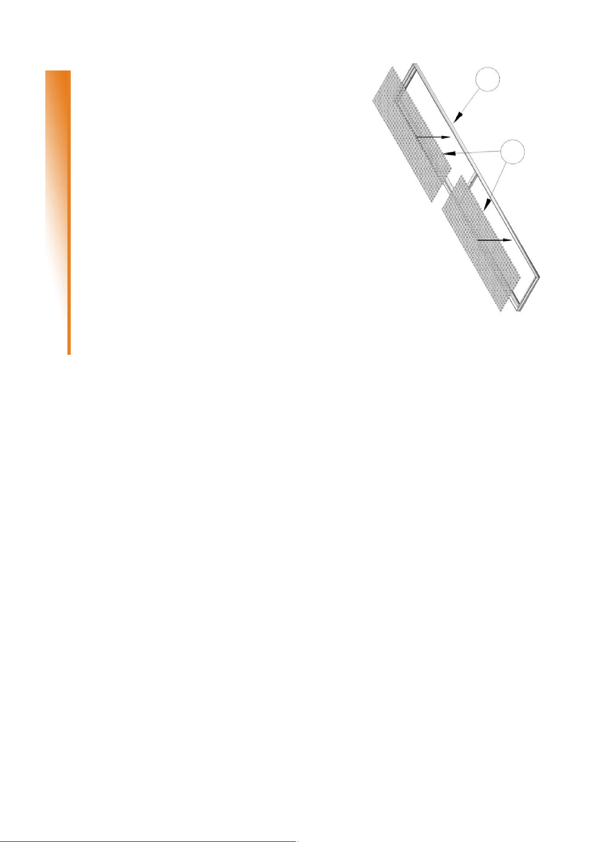
BK
BL
be shortened to suit the system
layout and also to accommodate
corner reflector sections.
2.15.2 Shortened modular grille
assemblies.
2.15.2.1 Carefully disconnect one end
support from the standard 2.44m long
grille support frame (BK).
2.15 Installation of Slimline ’M’ Decorative Grille System
nb. Reflectors removed for clarity
m
m
BJ
2.15.2.2 Cut the side support to
the required length, ensuring that
the cut ends are square and free
from burrs. Reposition the end
BM
BF
0
1
2
1
support and mark the fixing hole centres onto the side supports.
Drill 2 sets of 5mm diameter holes through the side supports and
secure frame using 8mm pop rivets.
The Slimline ‘M’ decorative grille system consists of standard 2.44m long modular grille assemblies which are
supported from the underside of the radiant tube. The modular assemblies are fitted in tandem along the system.
2.15.1 Standard 2.44m long modular grille assemblies
2.15.1.1 Starting at each system end vent, position the ‘U’ bolts (BB) around the radiant tube, through
the clamp bridge (BC) and secure using with M8 locknuts (BE) approximately 10mm from the ends
of the threads.
Ensure that the distance between ‘U’ bolts is 1210mm. The ‘U’ bolt assemblies should be
positioned perfectly square to ensure that the modular grille assembly lies
horizontal when fitted.
2.15.1.2 Fit 2 eggcrate grille pieces (BL) into the standard 2.44 long
grille support frame (BK).
2.15.1.3 Raise the modular grille assembly (BJ) and pass
the threaded ends of the three ‘U’ bolts through the
three sets of fixing holes.
2.15.1.3 Fit the M8 dome head nuts (BM) and
2.15.2.3 Cut grille (BL) to the required length and position into the
support frame.
2.15.2.4 Ensure that the ‘U’ bolts are positioned onto the tube to
suit the new support frame fixing positions.
2.15.2.5 The shortened modular assembly can now be fitted
to the heater using the procedure as stated in 2.15.1
m
m
0
1
2
1
BC
BE
BB
washers (BF) to the threaded ends of the
‘U’ bolts. Check that the module is
secure.
A standard 2.44m long
modular grille
assembly can
47
BB. ’U’ Bolt - C110548; BC. Clamp Bridge - C110549; BE. M8 Nut - 5441; BF. M8 Washer - 5445; BJ. Modular Grille Assembly - L106000-SUB; BK. Support Frame - L106004;
BL. Eggcrate Grille - L106015; BM. M8 Dome Nuts - L106007
Page 48

2.16 Installation of Blanking Shields
BN
BP
BD
BE
nb. Reflectors removed for clarity
BF
m
m
0
0
0
1
BC
BE
It may be necessary to prevent heat being directly emitted from certain points along the
radiated tube. Blanking plates are available in either 1250mm or 400mm sections,
which prohibit this. 2.16.1 Installation 2.16.1.1 Locate radiant tube area to be blanked. Position the ‘U’ bolts (BB) around the
radiant tube, through the clamp bridge (BC) and secure using with M8 nuts (BE). Ensure that the distance between the ‘U’ bolts is approximately 1000mm for the 1250
blanking plate or 200mm for the 400 blanking plate. The ‘U’ bolt assemblies should be positioned perfectly
square to ensure that the blanking plate lies horizontal
when fitted.
2.16.1.2 A retaining plate (BD) is
positioned on the underside of the
blanking plate (BN) at each ‘U’
bolt assembly position and
48
secured using M8 nuts
BB
BB. ’U’ Bolt - C110548; BC. Clamp Bridge - C110549; BD. Clamp Plate - C11044 9; BE. M8 Nut - 5441; BF. M8 Washer - 5445; BN. Blanking Shield 1250mm - L10602 0-1;
(BE) and washers (BF).
BP. Alt Blanking Shield 400mm - L106020
Page 49

2.17 Installation of Undershield Deflectors
nb. Reflectors removed for clarity
BR
BT
2.17.1.3 Ensure that
the distance between
the munsen rings is
BU
BS
approx 2360mm apart.
Repeat the above procedure for the second munsen ring.
2.17.1.4 Pass an M12 set pin (BS) through a M12 washer (BU) and
through the slot on the undershield and loosely attach the M12 locknut
(BT). Repeat for the second set pin.
2.17.1.5 Offer the undershield deflector up to the munsen rings. Locate
the set pins to the boss and tighten. Secure assembly by tightening
locknut. Repeat for second munsen ring.
An Undersheld Deflector (BR) is positioned beneath the radiant tube, usually at the first
half of the firing leg (nearest the burner), although this can be positioned at any point if
being used purely as a heat deflector for clearance purposes. The oversized munsen rings (BQ) supplied will allow the undershield deflector to move
with the expansion and contraction of the radiant tube. 2.17.1 Installation
m
m
0
6
3
2
Each undershield has two slots, 25mm in length at each end of the deflector. These
slots are used to position the munsen rings apart. Mark the first point of
the deflector on the radiant tube. Use the undershield (or a tape
measure if required) to mark the second point. 2.17.1.1 The munsen rings (BQ) are supplied
assembled. Using a flat head screwdriver
remove both screws retaining the two parts
together. 2.17.1.2 Offer one half, then
49
BQ
BQ. 100mm Munsen Rings - 6532; BR. Undershield 2440mm - 1350; BS. M12 x 50 Set Pin - 5501-1; BT. M12 Locknut - 5501
the other onto the
radiant tube at the first
mark with the boss
facing downwards.
Replace the screws and
tighten.
Page 50

X2
X1
Y
2.18 Installation of Acoustic Enclosure
X3
X4
CC
CA. Lid Assembly - 201117; CB. Side Panel Assembly - 201115; CC. Base
Assembly - L103075-SUB; CD. M6 x 16 Bolts and Washers - 5416 & 5425;
2.18.1.3 Locate fan
assembly (Y) and position in correct orientation on fan stool located
on base assembly (CC). Ensure anti-vibration mountings are used
and secure using nuts and washers supplied. Anti-vibration mountings are supplied as a kit of parts (X1 - X4).
X1-4 Anti-vibration Mount Kit - L103045-SUB; Y. Fan;
CA
CD
CB
CC
The Nor-Ray-Vac Acoustic enclosure reduces the noise from the Vacuum
fan where it is mounted inside the working area and noise is an issue. It is
constructed of noise reducing panels assembled to form a cube. The
acoustic enclosure is weatherproof and thus can be ex ternally located. 2.18.1 Dis-assembly
The acoustic enclosure is delivered pre-assembled so some dismantling
will be required to assemble the fan motor and flue.
2.18.1.1 Remove 15 off M6 bolts and washers (CD) along the lid (CA)
edge as indicated and withdraw lid
assembly (CA)
2.18.1.2 Remove 13 off
M6 bolts and
washers (CD)
along the
bottom edge
50
and side as
indicated.
Remove side
panel (CB)
Page 51

Dims: (hwd) 736x760x670mm Weight: 25.0kgs (excluding Fan) Part: L103101-SUB
CE
Installation of Acoustic enclosure cont
2.18.3 Suspension instructions for acoustic enclosure 2.18.3.1 Suspension can be made from building steelwork using 12mm
diameter drop-rods (not supplied) onto each hole of the base frame. 2.18.3.2 Alternatively, the base frame can
be secured to suitable platform using
M12 bolts, nuts and washers.
CD
CF
CG
2.18.2 Re-assemble 2.18.2.1 Replace side panel (CB). Refit 13 off M6 bolts and washers (CD)
along the bottom edge and side as indicated. 2.18.2.1 Replace lid (CA). Refit 15 off M6 bolts and washers (CD) along
the lid edge as indicated.
CA
51
CB
CC
CA. Lid Assembly - 201117; CB. Side Panel Assembly - 201115; CC. B ase Assembly - L103075-SUB; CD.
M6 x 16 Bolts and Washers - 5416 & 5425; CE. 12MM All thread - (not supplied); CF. M12 Washers - (not
supplied); CG. M12 Full Nuts - (not supplied)
Page 52
2.19 Installation of the Flue Silencer
2.19.3 Vertical configuration. 2.19.3.1 Connect the one side of the flue silencer
(CH) to the flue by means of coupler (G). The
other side of the flue silencer is connected to
the remaining flue via a tube coupler (G) 2.19.3.2 Support bracketing points are
positioned along the length of the flue
silencer box.
G
CH
G
Silicone sealant in
all the joints
G
U
T
CH
G. Tube Coupler - C112120 (Ø150); T. Expansion Joint - 7532;
U. Jubilee Clip Ø150 - 7542; CH. Flue Silencer - A517360-SUB;
The Nor-Ray-Vac Flue Silencer reduces the external break-out noise from
the flue terminal. This is essential for systems installed adjacent to
residential and educational areas. It is constructed of noise reducing
baffles assembled in an enclosure. 2.19.1 Assembly
The flue silencer box has 150mm diameter spigots at either end, and can
be fitted into the fan discharge flue, utilising standard 150mm diameter
connectors supplied. The flue silencer (CH) can be fitted in the horizontal or vertical sections of
the flue. 2.19.2 Horizontal configuration. 2.19.2.1 Connect one side of the flue silencer (CH) to the expansion joint
(T) by means of a jubilee clip (U). The other side of the flue silencer is
connected to the flue via a tube coupler (G) 2.19.2.2 Support bracketing points are positioned along the length of
52
the flue silencer box.
Dims:
(hwd) 300 x 450 x 300mm
ø150 spigots x 140 long,
brackets 50mm
tall.
Weight: 6.0kgs
Page 53

2.20 Installation of the Fan Motor Muff
CL
CM
CK
CJ - Motor Muff
2.20.1.3 Fix the muff to the
CM
CL
fan back bracket using 2
bolts (CK), nuts (CL)
and washers (CM) as
indicated.
The Nor-Ray-Vac Fan Motor Muff is ideal when the vacuum fan is
mounted within a plant room or unused room to dampen down the fan
motor noise. It is constructed of noise reducing panels assembled in an
enclosure. 2.20.1 Assembly
2.20.1.1 Fit the motor muff (CJ), over the motor of the vacuum fan. 2.20.1.2 Fix the muff to the fan motor stool using 4 bolts (CK), nuts (CL)
and washers (CM) as indicated.
Dims:
(hwd) L103053 - 300 x 370 x 320mm
(hwd) L103054 - 330 x 410 x 320mm
brackets 50mm
Weight:
CK
CJ. Motor Muff - L103053 (B80/B160/B300), L103054 (BH300);
CK. M10 x 25 Set Pin - 5481; CL. M10 Nut - 5487;
CM. M10 Washer - 5480
8.0kgs
53
Page 54

2.21 Installation of the End Vent Silencer
CP
Assembled EVM Silencer
CR
AS
AQ
CN
AQ. EVM Outer Plate; AS. EVM Fastener; CN. EVM Silencer - L104051-SUB;
□130 x 195mm long
The Nor-Ray-Vac End Vent Silencer - reduces the break out noise from
the inrush of air into the combustion tube when installed within areas
where noise is an issue. It is constructed of noise reducing panels
assembled in an enclosure. 2.21.1 Assembly
2.21.1.1 Remove cover plate
(AQ) of the end vent
module by releasing
the 2 set screws
(AS). 2.21.1.2 Offer the
silencer (CN), up to
the cover plate of
the end vent module
and attach by fixing
the 4 set screws
(CP) and washers
(CR) to the hank
bushes in the end of
the silencer box. 2.21.1.3 Re-attach the
54
cover plate (AQ) to the
end vent module and fix
in position using the 2 set
screws (AS).
Dims:
(hwd)
Weight: 4.0kgs
CP. M6 x 12mm Set Pin - 5417-1; CR. M6 Washer - 5405
Page 55
3. Commissioning Instructions.
These appliances should be commissioned by a qualified engineer.
3.1 Tools Required.
The following tools and equipment are
advisable to complete the tasks laid out in this
manual.
Various
Pozidrive
Screwdrivers
Suitable alternative tools may be used.
Various
Flat Head
Screwdrivers
Manometer
Spanner
Set
3.2 General.
Under normal working conditions it is
recommended that the Nor-Ray-Vac ‘LR’ series
system is regularly maintained to ensure long
life and efficient operation.
Maintenance is required only once per year.
In dusty or dirty conditions more frequent
maintenance is desirable. Servicing work must
setting. Refer to section 3.3.1.8
3.3.1.5 Check gas is turned on at meter and
take meter gas pressure reading.
Fit pressure manometer to the inlet pressure
test point on the burner furthest from the gas
supply and with all burners off observe
pressure reading. Turn off gas at meter and
again observe reading. If pressure falls check
system for leaks.
be carried out by a qualified gas service
engineer.
Important
When maintaining or servicing the Nor-Ray-Vac
‘LR’ series systems:
• Never rest anything, especially ladders
against heating system.
• Isolate gas and electrical supplies before
commencing any service work.
3.3 Commissioning Procedure
3.3.1 Start Up Checks
3.3.1.1 Check that the installation is to the
design layout drawing and installed in
accordance with the installation instructions.
3.3.1.2 Check installation electrically. Ensure
that the vacuum fan, inverter, burners and
control panel are wired correctly to diagrams
provided.
3.3.1.3 Ensure that each burner is electrically
disconnected at the plug/socket.
3.3.1.4 Set individual burner delay timer
dip-switches (located in each burner) to required
Injector pressure
test point.
The gas pressure at the burner inlet
connection must not exceed 50 mbar (20in
wg).
3.3.1.6 Start the vacuum fan.
For various controllers/BMS systems it may be
necessary to adjust the set point to above room
temperature.
For B80/B160 and B300 fans with an inverter
panel, check that the display states “rdy” (ready)
3.3.1.7 Check for correct fan rotation.
55
Allen
Key
set
Gas inlet
test point
Adjustment screw under
cap to set injector pressure
Page 56
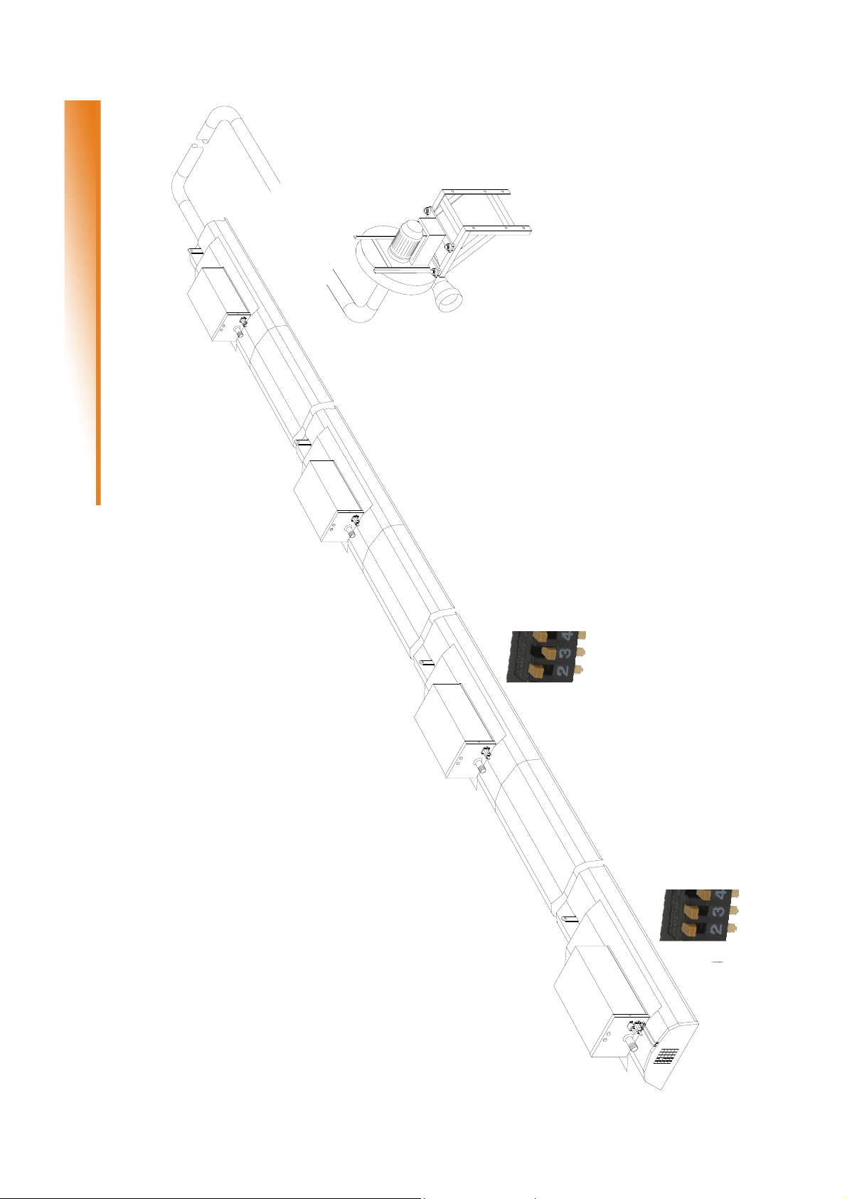
In-line
BURNER 1
3.3.1.8 Burner Timer Dip-switch Adjustment
In-line
BURNER 2
In-line
BURNER 3
In the event there are more than four burners in the radiant branch,
set the dip-switches as below. 5 burners in a single branch:
Burner 1 - dip-switch 1
Burner 2 - dip-switch 1
Burner 3 - dip-switch 2
Burner 4 - dip-switch 3
Burner 5 - dip-switch 4
Each burner is fitted with an adjustable burner delay timer. The timer is adjusted using
dip-switches located on top of the timer casing. The dip-switches are labelled 1, 2, 3 and 4. These numbers correspond to the burner
positions within the radiant branch. The burner located nearest to the exhaust fan in that branch is noted as Burner 1, this
is the case irrespective of how many other burners are in that branch.
The burner directly behind burner 1 is always noted as Burner 2, the burner
directly behind Burner 2 is Burner 3 and so on finishing at the End Vent
Burner. Set the burner timer dip-switch.
End-vent
BURNER 4
For example, the timer on burner 1 is set by sliding
the white dip-switch, positioned above the
number 1, towards the number. The timer
on burner 2 is set by sliding the white
dip-switch, positioned above the
number 2, towards the
number.
57
Page 57
3.3.1.9 Adjust the vacuum setting
The end vent vacuum is measured by removing
the protection cap on the tee piece in the air
impulse line on the end vent burner and
connecting a manometer.
3.4.6 Press the jog dial to enter. Rotate jog dial
until ‘LSP’ is displayed. Press jog dial to enter.
3.4.7 Rotate jog dial to adjust frequency. Press
jog dial to enter new value, causing the inverter
to change its speed.
3.4.8 Adjust the frequency until each burner has
lit.
Frequency is usually between 35 and 50 (Hz)
3.4.9 Press the ESC button twice to return the
inverter to the ’rdY’ display.
3.4.10 Remove power to the system and allow
fan to halt.
3.4.11 Return power to system. After a 30s
delay the fan should run and a red neon should
have illuminated on the rear of each burner.
3.4 B80/B160 and B300 fans ONLY
The use of an inverter on the standard B80,
B160, B300 fan system allows the end vent
suction to be adjusted by varying the low speed
setting of the inverter within the local relay unit.
3.4.1 Ensure that electrical supply to the end
vent modules and burners in each branch are
connected.
3.4.2 Check that the fan and branch dampers
are fully open and secure.
3.4.3 Ensure the controller is in a programmed
ON function and above the actual room
temperature.
3.4.4 After a 30s delay the fan should run and
the inverter should be showing the motor
frequency in the display.
3.4.12 Working at the radiant branch
FURTHEST AWAY from the fan, observe the
ignition of the burners. An amber neon should
illuminate on the rear of the burner.
3.4.13 If the dip-switches have been set
correctly, the burner closest to the manifold (last
on branch) should ignite first followed in order
by every burner towards the end vent burner.
Note: It may be necessary to temporarily break
the union at a burner in order to purge the gas
pipe of air.
When the branch has been running for 30
minutes check the end vent vacuum reading.
3.4.14 Re-adjust the frequency on the inverter (if
necessary) until the appropriate end vent
suction is achieved, this is given in the table
below.
3.4.5 Press the mode button 3 times until
‘COnF’ appears on the display.
Mode button:
Switches between
control/program modes.
(Only accessible with
door open).
Standard multi-burner systems 6.25
Special considerations
Escape button:
Exits a menu or
parameter.
Jog dial:
For navigation when
turned clockwise
or anticlockwise, or
selection/validation
when pressed.
Single 32LR End vent only 7.5
Single 38LR End vent only 8.25
Single 46LR End vent only 9.25
Three 46LR in a single branch 5.6
System
End vent
pressure
mbar
57
Page 58

3.4.15 Proceed to the next radiant branch closer
to the fan and commission in the same manner,
observing the ignition sequence of the burners
and amber neon's.
3.4.16 Check the end vent vacuum reading.
3.4.17 Adjust the branch damper (if necessary)
located at the end of the branch to bring the
vacuum readings in line with the normal
operating figure shown in the chart. Ensure that
damper is locked securely after adjustment.
A
B
Adjustment instruction for branch damper.
1 Loosen grub screw (A).
2 Turn adjustment lever (B).
3 Position of damper blade is indicated by
position of bent adjustment lever.
4 Tighten grub screw (A) to secure damper
position.
3.4.18 Repeat for any further branches (where
necessary), moving closer to the fan as each
branch is completed.
The vacuum setting procedure is now complete.
3.5 BH300 fans ONLY
(and fans controlled by NRV ‘logic’
driven LRU’s with no inverter)
End vent vacuum settings are made firstly by
means of adjusting the damper at the vacuum
fan inlet, this brings the end vent with the lowest
reading to the normal operating vacuum.
The dampers on each branch can then be
adjusted to bring the vacuum readings in other
branches to the normal operating figure.
Ensure that all dampers are locked securely
after adjustment.
3.5.1 Ensure that each burner is electrically
disconnected at the end vent module plug/
socket.
3.5.2 Check vacuum fan inlet and branch
dampers are fully open in the first instance and
secure.
3.5.3 Ensure the controller is in a programmed
ON and above the actual room temperature.
B
A
The fan inlet damper is integral to the fan inlet
condensate tee piece.
1 Loosen grub screw (A).
2 Turn adjustment lever (B).
3 Position of the damper blade is indicated by
position of bent adjustment lever.
4 Tighten grub screw (A) to secure damper
position when finished.
3.5.4 After a 30s delay the fan should run.
3.5.5 Working at the end vent burner
FURTHEST AWAY from the fan, measure the
vacuum pressure and adjust the fan inlet
damper to obtain over 8.7 - 10 mbar (above
3.6in wg) WHEN COLD.
58
Page 59
3.5.6 Remove power to the system and allow
fan to halt.
3.5.7 Ensure that each burner is electrically
re-connected at the end vent module plug/
3.6 Final Commissioning.
3.6.1 Check that the burner injector pressures
are zero ± 0.25 mbar (±0.1in wg). Adjust if
necessary.
socket.
3.5.8 Return power to system. After a 30s delay
the fan should run and a red neon should have
illuminated on the rear of each burner.
3.5.9 Working once more at the radiant branch
FURTHEST AWAY from the fan, observe the
ignition of the burners. An amber neon should
illuminate on the rear of the burner.
3.5.10 If the dip-switches have been set
correctly, the burner closest to the manifold (last
on branch) should ignite first followed in order by
every burner towards the end vent burner.
Note: It may be necessary to temporarily break
the union at a burner in order to purge the gas
pipe of air.
Allow the branch to run for 30 minutes.
3.5.11 Recheck the end vent burner
FURTHEST AWAY from the fan, measure the
vacuum pressure. Adjust the branch damper (if
necessary) to obtain the figure shown in the
table below.
End vent
System
pressure
mbar
Standard multi-burner systems 6.25
Special considerations
Single 32LR End vent only 7.5
Single 38LR End vent only 8.25
3.6.2 Check operation of thermostat controllers
a number of times, allowing the burner ignition
cycle to complete each time, checking that each
burner relights.
3.6.3 With all burners firing check the inlet gas
pressure at the burner furthest away from the
gas supply.
The minimum inlet pressure is 17.5mbar for G20
(Nat Gas), 20mbar for G25 (Nat Gas) and G31
(Propane) and 25mbar for G30 (Butane).
The difference between gas pressure at the
burner, with all the burners on and all the
burners off should not be more than 2.5 mbar
(1in wg).
3.6.4 Take gas consumptio n meter readings for
each separate NRV system or building heated
ensuring all other loads are off.
3.6.5 After the system has reached equilibrium:
take the following measurements.
a The flue gas temperatures entering the
Single 46LR End vent only 9.25
Three 46LR in a single branch 5.6
vacuum fan. The flue gas sample point located
on the vacuum fan tee is used.
b The surface temperature of the underside of
3.5.12 Repeat for any further branches (where
necessary), moving closer to the fan as each
branch is completed.
The vacuum setting procedure is now complete.
the tube at the end of each radiant branch.
c The surface temperature of the underside of
the tube at a point directly underneath each
combustion chamber suspension lug.
3.6.6 Reset thermostat controllers to required
setting.
3.6.7 Complete service report sheet.
Adjustment
screw under cap
to set injector
pressure
Injector pressure
test point.
59
Page 60

3.7 Typical Unequally Balanced System Layout
End vent
Pressure mbar
System
Standard systems - shown 6.25
Single 32LR End vent only 7.5
Single 38LR End vent only 8.25
Single 46LR End vent only 9.25
Special considerations
Three 46LR in a single branch 5.6
61
Page 61
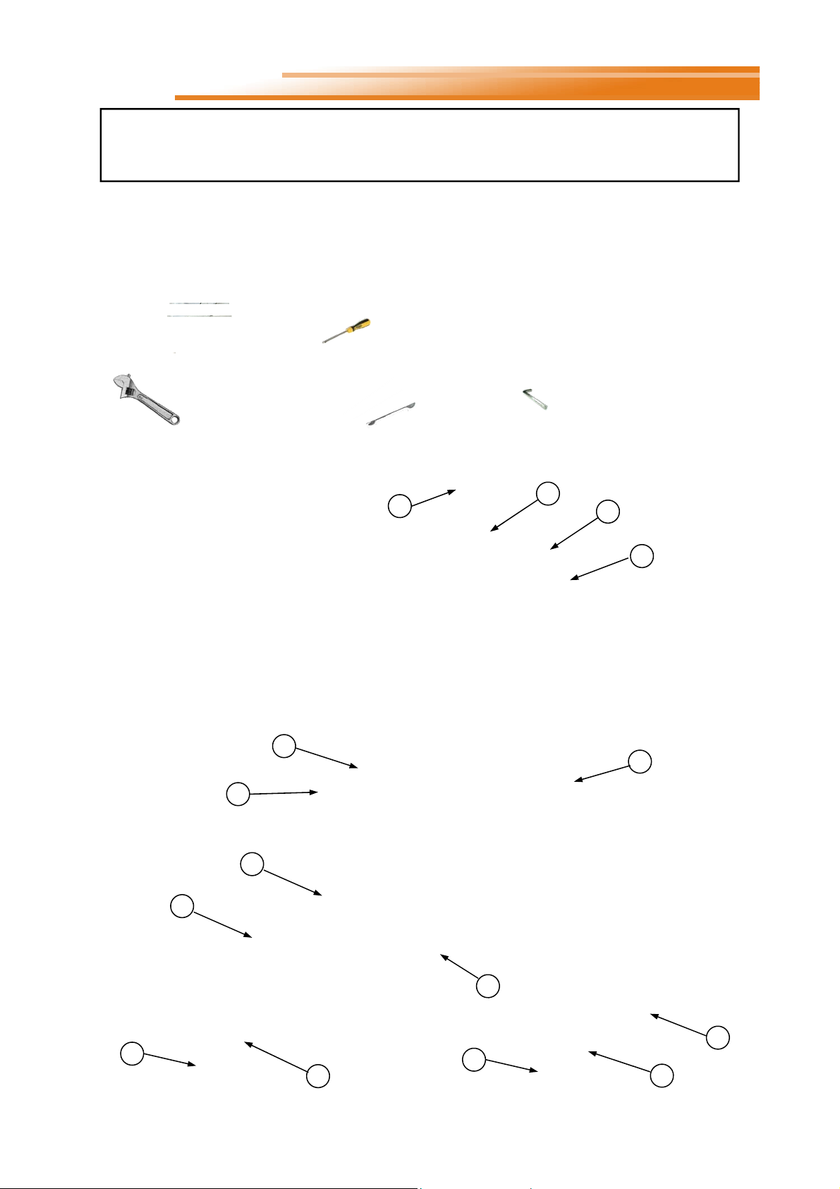
4. Servicing Instructions.
These appliances should be serviced annually by a competent person to ensure safe
and efficient operation. In exceptional dusty or polluted conditions more frequent
servicing may be required.
The manufacturer offers a maintenance service. Details available on request
4.1 Tools Required.
The following tools and equipment are advisable
to complete the tasks laid out in this manual.
Leather
Faced
Gloves
Large Adjustable
Spanners or 22, 26 &
27mm Spanners for
Gas Flex.
Various
Pozidrive
Screwdrivers
4.2 Burner Exploded Views.
Figure 6.a. LR Burner Head
6 Burner head casting – L100103-SUB
7 Burner port insert – L100155
8a Flame retention grid – L100171
8b Flame retention mesh – L100177
8c Flame retention plate – L100176
9 Air shutter plate - see selection chart
10 Burner jet - see selection chart
11 Electrode assembly – L100401
23 ½” plug – L100202
37 Set pin M4 x 6 – 5326-1
37
Spanner
Set
Suitable alternative tools may be used.
Various
Flat Head
Screwdrivers
Allen
Key
set
Soft
Brush
11
37
9
Assembly for
LR12 - 18
8b
37
23
8a
10
8c
6
Part assembly for
LR24 - 46 ONLY
7
7
36
8a
61
Page 62

Figure 6.b. LR Burner
33
31 34
39 37
2
15
3
32
19 18
42
4
16
34
25
26
20
13
14
12
1
1 Control housing base plate – L102001
2 Control housing lid – L102009
3 Full sequence gas controller – 2015
4 Multi functional gas valve – C111513 plus 900041
5 Air filter – L102013
6 Burner head casting – L100103-SUB
7 Burner port insert – L100155
8 Flame retention grid – L100171
9 Air shutter plate - see selection chart
10 Burner jet - see selection chart
11 Electrode assembly – L100401
12 Mains input filter – 201292
Mains lead (not shown) – 2125
13 Air pressure switch (EV only) – L104039
14 Bulkhead compression fitting (EV only) – L104073
15 Delay timer – L102025-SUB
16 Inline Socket (EV only) – 3123-5
Inline burner plug (EV only - not shown) – 3124
17 Wiring harness – E200067
18 Red neon light – 2180
19 Amber neon light – 2175
20 Gas inlet connection pipe ½” x 4” – 2360
21 Gas outlet inlet connection pipe ⅜” x 2½” – 2314-1
22 ½” x ⅜” reducing bush – 2320
23 ½” plug – L100202
36
24
17 41
22
28
37
9
23
37
10
21
27
43 35
44
6
24 Valve mounting bracket – L102020
25 Pressure switch bracket – L200025
26 Grommet (gas supply) – B200500
27 Grommet (13mm) – 2878
28 Burner gasket – L102032
29 Silicone gasket – L102031
30 Slide latch – L100200
31 Latch clip – L100201
32 Push clip – C110714
33 Wing nut – C111700
34 Set pin M4 x 12 – 5325
35 Set pin M4 x 10 – 5314
36 Set pin M5 x 10 – 5363
37 Set pin M4 x 6 – 5326-1
38 Washer M4 – 5322
39 Nut M4 – 5315
40 Torque Screw - 201093
41 Silicone tubing (EV only) – L100180-SUB
42 Silicone tubing (EV only) – L100181-SUB
43 Plastic tee (EV only) – L104200
44 Tee cap (EV only) – L104201
37
11
30
8
40
28
29
37
7
62
Page 63
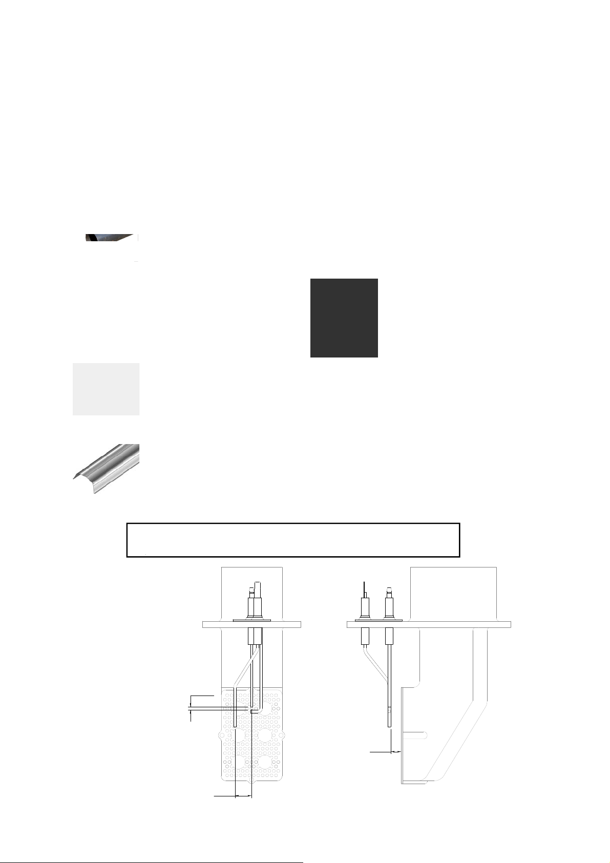
4.3 Vacuum fan
Inspect fan and flue ductwork for
any contamination.
Inspect expansion joints for
damage and replace if necessary.
4.4 Tubes
Inspect radiant tubes and fittings
internally. If there is any
appreciable build up of dust or
deposits the tubes should be
cleaned internally.
If corrosion is present replace as necessary.
Note It may be necessary to determine whether
chlorinated hydrocarbons are being used by the
client.
4.5 Tube couplers
Check for tightness.
Inspect for evidence of holes and
cracks and replace if necessary.
4.6 Reflectors
Check for overlaps and re-adjust
if necessary.
The reflectors may be cleaned
with a soft cloth and detergent in
water.
4.7 Condensate trap
Inspect for dirt and scale and
clean if necessary.
4.8 Burner electrodes
Check ceramic visually for build
up of carbon or cracks.
Check the spark distance and
position of the electrodes relative
to the burner head, replace if
necessary (see fig.7).
4.9 Burner head
Check condition of burner head
insert and flame retention grid
and replace if necessary.
4.10 Filter
Replace if contaminated with dirt.
4.11 Combustion Chamber Viewing Window
Window should be clean and free
from cracks.
Replace if necessary.
Re-commission system after servicing (see section.3)
Figure 7.
Burner Electrode Details
3.5mm
18mm
13mm
63
Page 64

5. Spare Parts.
Required Spares
In order to aid troubleshooting and servicing we
recommend that the components shown in this
section should be stocked.
Item
Ignition
Controller
Nat Gas Valve
Twin Solenoid
220/240
Valve Mini
Harness
Mains Input
EMC Filter
Part No. Description
2015
C111513
900041
201292
Note Any spare part components that are
not approved by AmbiRad could invalidate
the approval of the appliance and validity of
the warranty.
Item
Amber Neon
(Burner On)
Red Neon
(Mains On)
Inline Burner
Socket
Part No. Description
L104039 Pressure Switch
2175
2180
3123-5
Rectification
Lead
Mains Input
Cable
L100401 Ignitor Assembly
2243-1 HT Spark Lead
2243-2
2125
Inline Burner
Plug
Vacuum Test
Nipple
Main Harness
End Vent
In-line
3124
L104200
L102026 Burner Timer
E200067
E200068
2104 Lockout Relay L102013 Burner Air Filter
2197 Webber Valve
64
Lockout Relay
Base
2108
Page 65
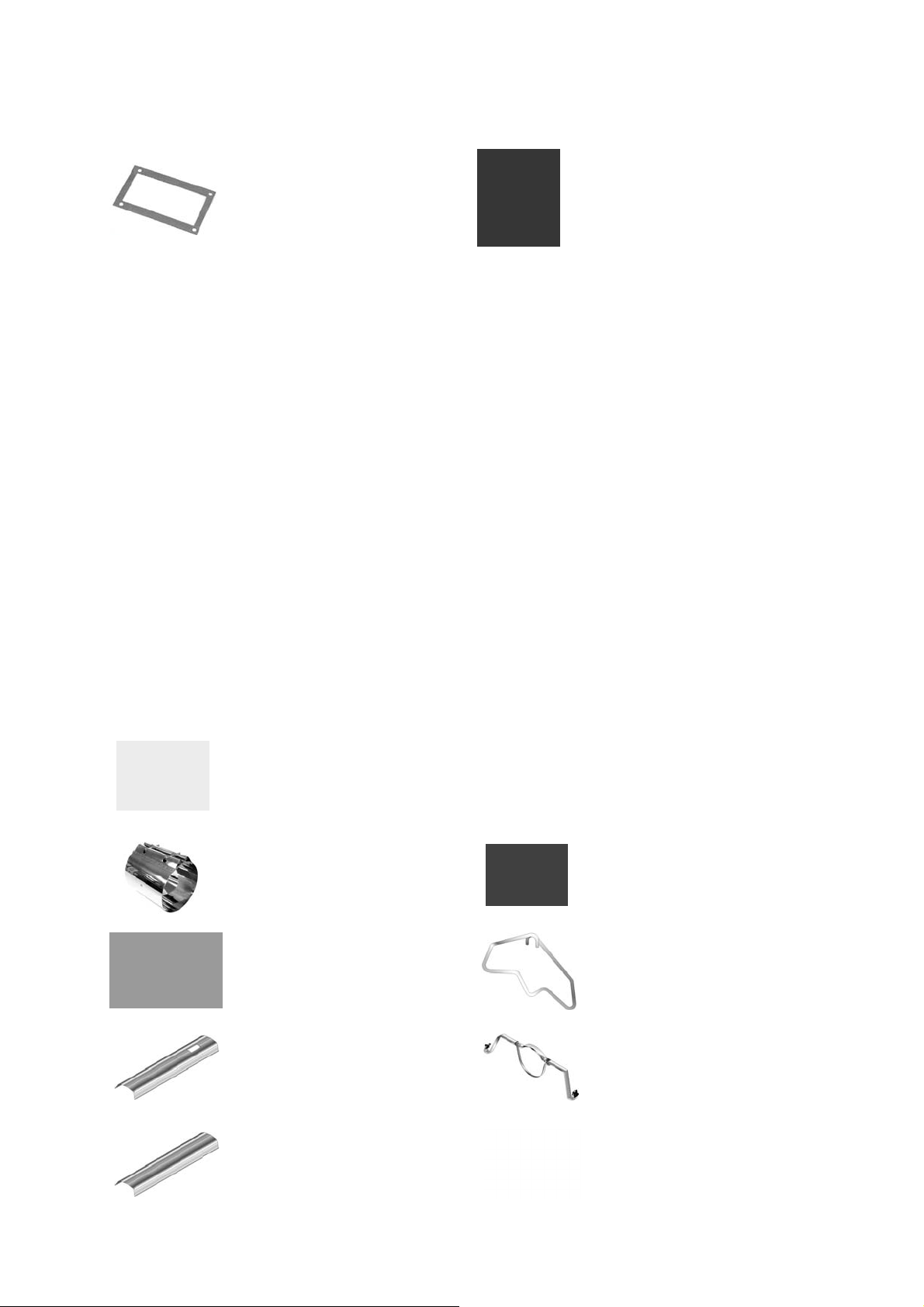
Fan
B80
B160
B300
Part No. Description Item Part No. Description
Item
Burner Head
L102032 Burner Gasket
Assembly
LR12-18
LR24-46
Flame Retention
L100155 Ceramic Insert
Grid
LR12-18
LR24-46
A523500 Mica Window
C110350 Window Gasket
201760
201761
201762
Sight Glass
Cover
End Vent
Module
Inverter
1.5kW B80/B160
2.2kW B300
L100102-SUB12-18
L100102-SUB
L100175-SUB
L100171
A571202
EVM
900088
900089
Fan
BH300
100mm (4”)
Tube Coupler
150mm (6”)
Tube Coupler
Combustion
Chamber
Combustion
Chamber
Reflector
201763
C112110
C112120
L101020-SUB
L105050
Contactor/O’load
BH300
Fan Expansion
Joint
Suspension
Bracket
Reflector
Support Bracket
900088
7532
7542 Jubilee Clip
C110500-SUB
L201008-SUB
Standard
Reflector
L105024
6524 Speedlinks
65
Page 66

NRV LR Injector/Air Shutter selection chart
Gas Burner
12 3.6 L100336 13 L100322 14.5 L104102
18 4.4 L100544 17 L100321 16 L104101
Natural
G20
Natural
G25
24 4.9 L100549 19.5 L100320 24 L104100
32 5.4 L100554 22 L100314 27 L104093
38 5.8 L100558 24 L100316 32 L104092
46 6.3 L100563 26.5 L100318 - 12 3.7 L100537 13 L100322 14.5 L104102
18 4.6 L100546 17 L100321 16 L104101
24 5.2 L100552 19.5 L100320 24 L104100
32 5.8 L100558 22 L100314 27 L104093
38 6.3 L100563 24 L100316 32 L104092
46 6.9 L100569 26.5 L100318 - -
Jet Size dia mm
Part number
Sutter Size dia mm
Part number
EVM Orifice Plate dia mm
Part number
Butane
G30
Propane
G31
12 2.6 L100526 13 L100322 14.5 L104102
18 3.2 L100532 17 L100321 16 L104101
24 3.7 L100537 19.5 L100320 24 L104100
32 4.2 L100542 22 L100314 27 L104093
38 4.6 L100546 24 L100316 32 L104092
46 5.1 L100551 26.5 L100318 - 12 2.9 L100529 13 L100322 14.5 L104102
18 3.5 L100535 17 L100321 16 L104101
24 4.0 L100540 19.5 L100320 24 L104100
32 4.4 L100544 22 L100314 27 L104093
38 4.8 L100548 24 L100316 32 L104092
46 5.2 L100552 26.5 L100318 - -
66
Page 67

6. Fault Finding Guide.
Symptoms Possible causes Remedy
Vacuum fan is running but there is no
power at burner. Neon lights are off.
Red neon comes on but ignition
sequence does not start and amber
neon remains off.
Red neon comes on. Amber neon
comes on for ignition period; then
amber neon goes off.
Red neon comes on. Amber neon
comes on for ignition period, burner
lights for a short time and then goes
out. Amber neon off.
End vent vacuum too low (ie below
6.25 mbar (2.5in wg). Check section
3, commissioning for exact vacuum
details.
Thermostat is satisfied. Check to see that thermostat is calling for heat.
No power at burner. Check for 240V supply.
Blown fuse in supply to heater. Check and replace if necessary.
End vent vacuum too low. Vacuum at end vent should be 6.25 mbar
Air pressure switch on end vent burner not
opening.
3 way air valve (if fitted) in end vent burner not
opening.
No power out from end vent burner. Check for loose or broken wire or faulty relay.
Loose or broken leads to full sequence gas
controller.
Fault in full sequence gas controller. Replace.
No ignition spark. Check for loose or broken high tension lead to
Fault in full sequence gas controller. Replace.
Insufficient gas supply to burner. Check service cock is open and gas pressure
Gas solenoid valve not opening. Check for loose or broken wires to the gas
Injector pressure not set at zero. Check and adjust.
Incorrect aeration. Check that air shutter plate on mixing chamber
Flame probe faulty or lead detached. Check for broken ceramic.
Fault in sequence gas controller. Measure flame current.
Polarity of line and neutral incorrect. Check for correct polarity of the electrical
Burner earth is poor. Check and ensure burner is correctly earthed.
Full sequence gas controller faulty. Replace.
Incorrect aeration. Check that air shutter plate on mixing chamber
Branch damper closed or broken. Open branch damper until end vent vacuum is
Fan rotation incorrect. Reverse two phase wires on 3 phase motors.
Fan speed wrong. Check voltage at motor. Replace if necessary.
Fan impeller loose or defective. Tighten or replace if necessary.
Restriction to fan inlet. Clear restriction, repair flue duct.
Air leaks into system via poor joints. Replace defective tube couplers gaskets or
Insufficient fall of system towards fan allowing
condensate blockage.
Non return valve sticking open on condensate
trap assembly.
67
(2.5in wg). Check for air leaks on burner.
Check and replace if necessary.
Check and replace if necessary.
Check and repair.
spark electrode.
Check spark gap and position for spark
electrode
Check ceramic is not cracked.
Check for loose earth wire connection on full
sequence gas controller.
is available at inlet to gas valve.
valve.
Check for adequate end vent vacuum.
Replace valve if necessary.
is correctly positioned.
Check for correct position of flame probe.
The minimum signal is 3μA (DC).
supply.
is correctly positioned.
6.25 mbar (2.5in wg).
Replace damper if necessary.
acoustic joints.
Reinstate system fall.
Clean valve or replace if damaged.
Page 68

7. Replacing Parts.
7.1 Removal of burner
assembly.
a Disconnect electrical supply at burner mains
inlet connection.
b Turn-off gas supply at service cock and
disconnect union.
b1 On EVM burners, remove the vacuum tubes
by releasing the two compression fittings (14).
c Release the slider latches (30) from the
underside of the burner base plate (1).
i Remove the burner heat shield.
j When replacing do so in the reverse order
ensuring that the gasket between the burner
heat shield and combustion chamber (28) is
undamaged or replaced.
k Check for gas soundness.
7.2 Removal of gas valve.
a Remove burner assembly from combustion
chamber as detailed in 7.1.
b Secure burner head (6) and unscrew gas inlet
pipe (21).
c Remove burner set screws (37) and valve
bracket set screws (36) from burner base plate.
d Pull lid (2) apart and upwards from base (1).
Lid is attached to back plate via 2 screws (34).
e Remove lid by unscrewing set pins (34) from
back of base plate.
f Remove spark electrode assembly (11) (see
section 7.7)
g Release and remove the four set screws (40)
from the combustion chamber flange.
Retain combustion chamber gasket (28).
h Lift burner clear of combustion chamber and
withdraw.
68
d Withdraw burner head and valve from base
plate. Retain burner gasket for later (28).
e Secure burner head (6) and unscrew gas
valve (4).
f Replace in reverse order.
Page 69

7.3 Filter Replacement.
a Release the slider latches (30) from the
underside of the burner base plate (1).
b Pull lid (2) apart and upwards from base(1).
c Unscrew wing nut fastener (33).
c Pull lid (2) apart and upwards from base (1).
d Disconnect JST connection (3a).
e Disconnect ignition wire from controller (3b).
f Release three push clips (32) from controller
fixing holes.
g Remove controller (3)
d Slide filter (5) out of location brackets.
e Replace in reverse order.
7.4 Controller Replacement
a Disconnect electrical supply.
b Release the slider latches (30) from the
underside of the burner base plate.
69
h Replace in reverse order.
7.5 Pressure Switch
Replacement (EVM ONLY).
a Disconnect electrical supply.
b Release the slider latches (30) from the
underside of the burner base plate.
c Pull lid (2) apart and upwards from base (1).
d Disconnect both silicone tubes (42 & 43) from
pressure switch (noting connection orientation).
Page 70

e Disconnect three electrical cables from
pressure switch (noting connection orientation).
f Remove fixing screws and nuts from the
pressure switch bracket and withdraw.
g Remove retaining screws from bracket to
pressure switch and remove unit
h Replace in reverse order.
7.6 Sequence Timer
Replacement.
a Disconnect electrical supply.
b Release the slider latches (30) from the
underside of the burner base plate.
c Pull lid (2) apart and upwards from base (1).
d Remove controller as described in section 7.4
e Disconnect electrical connection from the
timer.
f Remove fixing screws from timer bracket and
withdraw.
g Remove timer from the insulation wrap and
remove unit.
h Replace in reverse order.
7.7 Electrode Assembly
Replacement.
a Disconnect electrical supply.
b Release the slider latches (30) from the
underside of the burner base plate.
c Pull lid (2) apart and upwards from base (1).
d Remove fixing screws (37) from electrode
mounting flange (11).
e Carefully withdraw electrode assembly from
burner - noting electrode orientation.
f Replace in reverse order.
7.8 Injector Replacement.
(See figure 6a)
a Turn off gas and disconnect electrical supply.
b Release the slider latches (30) from the
underside of the burner base plate (1).
c Pull lid (2) apart and upwards from base (1).
d remove fixings screws (37) and air shutter
plate (9) from top of burner casting.
e Remove plug (23).
70
Page 71

f Unscrew brass jet (10) inside mixing chamber
using 8mm allen key and withdraw through 1/2in
BSP hole.
b Unscrew dome nuts (47) and spring washers
(48). Remove sight glass cover (49), gasket (50)
and mica window (51).
c Replace in reverse order as shown ensuring
components are re-assembled in correct order.
1. Mica Window
A523500
2. Window Gasket
C110350
3. Sight Glass Cover
A571202
4. Spring Washers
5. Dome Nuts
L101040
A315110
g Replace in reverse order.
7.9 Combustion Chamber
V i e w i n g W i n d o w
Replacement.
a Turn off the system including the vacuum fan.
71
Page 72

8. User & Operating Instructions.
8.1 To Start the Heater
1. Ensure that gas supply is turned on at
each burner.
2. Switch on electrical supply to heaters.
3. Ensure that the controls are correctly set
i.e.;
• Clock is correctly set.
• Heater program is correctly set.
• Required room temp is correctly set
4. The vacuum fan will operate and at the
same time the red neon lights will
illuminate at all burners. After 10 seconds
the burners closest to the exhaust fan in
each radiant branch will light, with both red
and amber neons illuminated. After a
further 25 seconds the next burner in line
within each radiant branch will light and
after a further 25 seconds the end vent
burner will light.
5 If the lighting up sequence fails and lockout
occurs press the lockout reset button (if
available), or switch off the electrical
supply and restart after 40 seconds. If
lockout occurs three times consecutively
switch off and isolate the gas and
electricity supplies.
Contact the AmbiRad Service department.
8.2. To Switch Off Heater
1. Switch off electrical supply to the heater.
The burner will stop and the fan will shut
off.
2. If the heater is to be switched off for
periods in excess of one week it is highly
recommended that both the gas and the
electrical supplies are turned off.
8.3. Routine Maintenance between Service
Intervals
After ensuring that the heater is cold and
mains electric isolated, cleaning of the
reflectors with a soft cloth and a mild
detergent (non solvent based cleaners only)
in water can be undertaken.
Additional removal of dust from the radiant
tubes, burner and heat exchanger can be
undertaken.
8.4 Frequency of Servicing
The manufacturer recommends that to
ensure continued efficient and safe
operation of the appliance, the heater is
serviced annually by a competent person
e.g. every year in normal working conditions
but in exceptional dusty or polluted
conditions more frequent servicing may be
required.
The manufacturer offers a maintenance
service.
Details are available on request.
For Service requirements, please contact
AmbiRad.
For further technical and service support
visit our Support Information Database at
www.s-i-d.co.uk
Note This notice must be fixed alongside the
electrical service switch. On some systems only
the end vent burner contains a delay timer. In
this instance the inline burners will light
simultaneously and the end vent burners will
light after an 80 seconds delay.
AmbiRad Limited Fens Pool Avenue
Brierley Hill West Midlands DY5 1QA
United Kingdom.
Telephone 01384 489700
Facsimile 01384 489707
Email [email protected]
Website www.ambirad.co.uk
Technical Support www.s-i-d.co.uk
AmbiRad is a registered trademark of AmbiRad Limite d. Because of continuous product
72
innovation, AmbiRad reserve the right to change product specification without due notice.
Document reference number GB/NRV/193/0711
 Loading...