

Page 1
THE TRILEVELSYNC LOCKIT BOX
Timecode, Videosync, Trilevelsync, Wordclock,
AES-3 Black Audio Generator
ACL 203
Description and instructions for use
AMBIENT RECORDING GmbH
Schleissheimer Str 181 C,
D-80797 Munich Germany
Te+49 89 6518535 Fax+49 89 6518558
Email: info@ambient.de
internet: www.ambient.de
Page 2

1
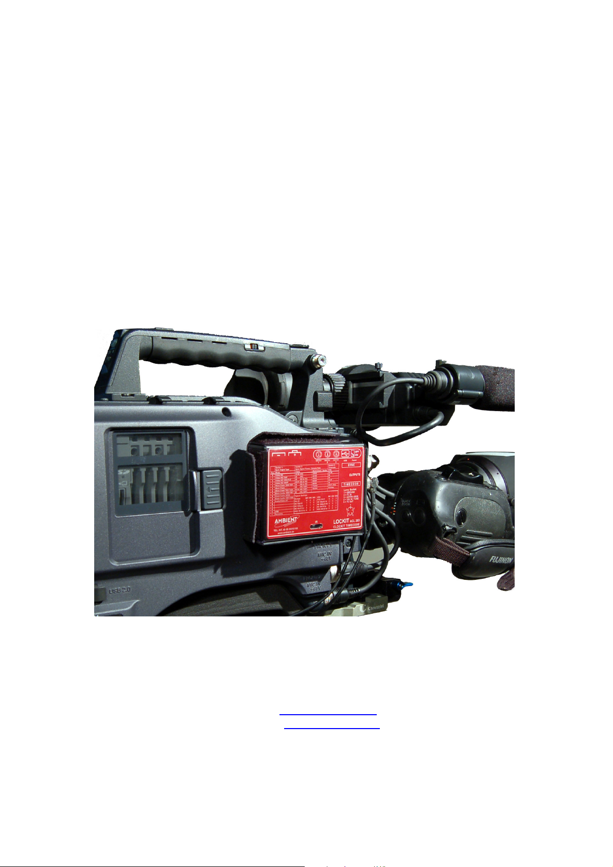
The Lockit synchroniser ACL 203
Description
The Ambient Lockit ACL 203 is a highly accurate portable timecode and video
sync generator. Audio and video machines such as DAT, harddisc and DVD
recorders and HD and Digibeta cameras can be synchronised to the Lockit box,
thus giving very low drift between machines, allowing multicamera shoots to be
carried out without cables or timecode radio links.
Typically, the drift will be less than one half frame a day, giving problem free
editing and syncing in post production.
The Lockit can be used in any recording situation where the accuracy of the TC
generators in the different machines is not known and where a cable connection
is not possible. Each machine is jamsynced and Genlocked, (if possible,) to its
own Lockit which is synced to a common source before the machines start. The
Lockit can be jam synced with external timecode, set using the Ambient
Controller ACC501 via ASCII through cable or Infra Red, or set by Aaton
"OrigenC" ASCII code.
Special Features
• Clockit tunable reference oscillator for timecode generation gives typically
less then one half frame a day timecode drift.
• Hightly accurate DTCXO reference oscillator. Can be calibrated in the field
to 0.2ppm using Clockit Controller ACC101 or ACC501.
• Crystal oscillator for video and trilevelsync locked to reference oscillator
low jitter high stability signals.
• 24, 23.98, 25, 29.97, 30 Frame Timecode locked to PAL, NTSC and HD
formats (SMPTE 296M and SMPTE 274M), Wordclock or AES-3 black audio
in all standard sample rates with pull-up and pull-down.
• Drop frame timecodes can be selected
• Extensive unit monitoring through 2 LEDs
• DC/DC converter for long life. Please refer to 1.4 for battery lifetime and low
battery reference.
Page 3

2
1.1 Controls
All changes of the settings take effect only after reboot of the unit.
Exception: TC-lockout / userbit insert with dip switch 1
Yellow Switch: Main On/Off
Rotary encoder switches with 16 positions behind the battery lid:
Switch 1: Type of sync signal:
This switch determines what type of signal is present on the BNC connector next
to the edge of the unit.
Pos. A turns off the video signal / audio generator if used as time code genearator
only to save battery life.
Pos. E allows to set the unit by USB, ignoring switch settings.
Pos. F is for firmware upgrade via USB.
Switch 2: picture rate of genlock signal or sample rate of word clock / black audio,
depending on setting of SW 1:
The right video format or sample rate are selected here.
Switch 3: time code frame rate:
Select the required frame rate. Please mind that invalid settings, like a integer fps
rate with a pull down picture rate will not work together.
Switch 1: Sync Signal
Type
Pos. Mode Video Word Clock / Audio FPS
0 Video SD 23.98 (HD) 32000 23.98
1 Video HD 720P 24 (HD) 44100 24
2 Video HD 1080I/PsF 25 (SD & HD) 48000 25
3 Video HD 1080P 29.97 (SD & HD) 88200 29.97
4 Word Clock 1000/1001 30 (SD & HD) 96000 30
5 Word Clock 50 (HD 720P only) 176400 29.97 drop
6 Word Clock 1001/1000 59.94 (HD 720P only) 192000 30 drop
7 Black Audio 1000/1001 60 (HD 720P only)
8 Black Audio AES-3
9 Black Audio 1001/1000
A Audio/Video off
B
C
D
E USB
F Recovery
Switch 2: Sync Signal Frame / Sample Rate Switch 3: Time
Code frame rate
Page 4

3
Dip switches behind USB connector:
There are 4 dip switches behind the USB connector:
Nr. Description 0 / Off (up) 1 / On (down)
1 LTC-In Mode Set Time Code Insert Userbits
2 Battery voltage ref.
see below
3 Battery voltage ref.
4 Not assigned
Battery voltage reference:
dip switch 2 dip switch 3 battery type threshold
0 / Off
0 / Off
1 / On
0 / Off
1 / On
0 / Off
alkaline 2,2 Volts
NiMH rechargeable 2,4 Volts
Lithium battery 2,5 Volts
1.2: Examples for typical settings:
Europe SW1 SW2 SW 3 USA SW1 SW2 SW3
PAL 25 0 2 2 NTSC 29.97 0 3 3
HD 720/50P 1 5 2 HD 720/59.94P 1 6 3
HD 1080/24P 3 1 1 HD 1080/23.98P 3 0 0
WC 48K/25 fps 5 2 2 WC 48K/30 fps 5 2 4
AES-3 48K/25 fps 8 2 2 AES-3 48K/30 fps 8 2 4
1.3 LED Indicators
Upon boot, first one, then both LEDs will light up. Then the red LED will double
flash until the PLL is locked and sync signal is being generated. The LED will
flash in seconds pulse then.
When jamming, the red LED will stop flashing, the green LED starts doubleflashing. After 2 – 3 seconds, it will go into the normal “flash once per second”
mode.
Warnings:
Fast flashing red : Invalid setting selected.
Fast flashing green LED: Unit is in “recovery” mode.
Alternating fast red / green LED: Software or hardware error.
Double flash every 2 seconds: battery voltage below selected threshhold (see 1.1)
Page 5

4
Flashes / secs. 1s 2s 3s 4s
Normal X X X X
Userbit insert -- ----- -- ----- -- ---- -- ---- (short - long)
Batt. Low X X X X
Video not X X X X X X X
sync w. TC
Video. TC X X X X X X X X
async +
Batt low
1.4 Batteries, Powering.
The Lockit is powered by 2 Mignon cells (3volts). It is recomended to use Alkaline
cells or rechargeable NiMH batteries. Please see voltage reference chart above.
External power can be connected on pin 4 of the Lemo connector (6 – 16 Volts) or
via the USB connector (5.0 to 5.2 Volts maximum)
If the Lockit is being powered externally, the internal batteries can be fitted and
act as backup if the external power is removed.
Page 6

5
2.1 Setting the Lockit TC generator from external source
A. External timecode.
Insert an external timecode source 0.5 volts up tp 5 volts pp. With successful jam
sync the LEDs will go from red to green, then flash irregularly for about two
seconds untill the PLL has locked and video / sync signal is put out, then go to
the normal once per second mode
If they were on green (unit was jam synced before and is being rejammed), the
green LED will flash like after first jam.
Note: If the lockit loses sync through loss of power one can use the machine it is
coupled to, to resync with timecode. Even if the machine has a drift of several
frames an hour, there will not be a frame lost if the Lockit is rejammed within one
minute. However it is best to rejam the lockit with one of the clockit units running
in the system to avoid errors.
B. Setting with Aaton Origen C. or Ambient Controller**.
The Lockit and all clockit units are Aaton compatible. The Lockit is connected to
the Origen C or Ambient Controller with an Ascii cable and setting and time code
comparisons can be carried out. After setting the LED goes green. Remove Ascii
cable.
If using the Ambient Controller ACC501, ASCII communication may also use the
IR interface.
Please note: If the ACC501 is set to IR in the ASCII menue, serial communication
via cable is disabled.
**The ASCII protocoll does not transfer frame rates only time. Thus when setting with
Aaton the frame rate must be set to the frame rate required. The timecode will be
generated at the frame rate set by the dip switches.
2.2 Time code jam mde.
With TC connected the Lockit will jam only once and not rejam until the TC source
is disconnected for over 3 seconds. After 3 seconds of no TC at the input, the
redetection of a readable TC at the input will induce a rejam. Also Aaton ASCII is
locked out for 3 seconds.
Of course Timecode can be disconnected after jamming when the LED has gone
green.
• The Lockit box can be used as a TC gearbox in a jam once and run
configuration that will hold sync fo about 0.5 hours. The Lockit box can be
set to desired frame rate and be jammed from another frame rate
Most Crystal controlled machines are not more than 10 ppm different. In a
jam and run situation in which the Lockit and source were 10 ppm different,
a jam and run would lead to 0.5 Frame difference after half an hour at 30
Fps. In practice this will probably be much less especially if the TC source
used for jam also comes from a Lockit box.. Sync will only work if integer
Page 7

6
and Pull down frame rates are used together respectively. ie 24,25 30 Fps
together, and 29.97. 23.98 Fps together.
• This feature can be used to jam the lockit once to a playback timecode
Using a transmitter and receiver on the Lockit box. The lockit will jam once
to the incoming playback timecode and also ignore RF dropouts of up to 3
seconds. Note Playback TC of a Video player is often jittery and cannot be
read by a camera. The Lockit delivers smooth code and sync.
• Remote rejam of all Lockits can be implemented in a multicamera shoot
using a TC transmitter and receivers on all cameras.
2.3 Insert userbits in running time code
• In normal operation dip switch 1 is off and timecode jam is enabled. If after
jamming TC dips witch 1 is set “on” (down) then the Lockit will not rejam to
externally connected timecode but will extract userbits from this TC and
insert them in the Lockits running code without disturbing sync. The LED
will flash green in long / short bursts per second. In this way using an event
number in the userbits of an external timecode, all cameras can be userbit
updated without rejamming.
• Note: after setting dip switch 1 to “off” again, The ACL 203 will still not jam
when receiving the first time code. Only after disconnecting and
reconneting time code after 3 seconds it will jam again.
Page 8

7
3.1 Connectors:
Lemo Socket (mating cable connector FGG/JGG.0B.305.xxx):
pin 1 Ground
pin 2 LTC in
pin 3 ASCII in/out
pin 4 6-16 volt input Tune reference out 1.92 MHz
pin 5 LTC out
USB connector for setup or firmware upgrade, type mini-A
3.2 Dimensions Input/output voltagesS
• Size 100mm X 74mm X 26mm
• Weight 250 Grms without batteries
• TC input 0.1 to 5 volts pp
• TC output BNC 1 volts pp
• Video out 1 volt pp on 75 Ohm
3.3 Accessories
Supplied accessories:
- Pouch ACL-T
- BNC to BNC cable approx. 40 cm.
Optional accessories:
- Time code cable in XLR-3F / Lemo-5
- Time code cable in BNC / Lemo-5 (To jam from Digibeta camera with BNC
output socket)
- Time code cable out Lemo-5 to XLR-3M
Ambient Recording Gmbh, Schleissheimer str 181c D-80797 Munich, Germany
Tel int 49 89 6518535. FAX 6518558 Email info@ambient.de.
Internet www.ambient.de
Page 9

8
 Loading...