

Page 1
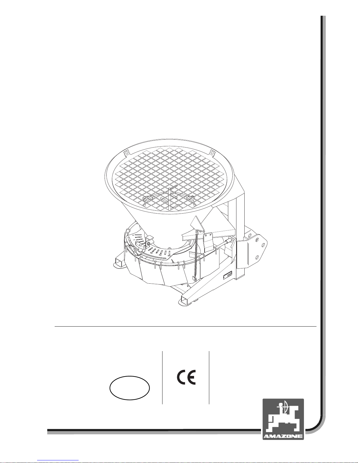
Winter application spreader
$0$=21((6
Operation manual and setting chart
D
4
9
2
0
5
H
a
s
b
e
r
g
e
n
-
zul.Nutzl.:
Ty
p
:
Masch.Nr.:
MG 786
DB 786 (GB) 02.02
Printed in Germany
a
Before starting work,
please carefully read
and adhere to this
operation manual and
safety advice.
GB
Page 2

DB 534 02. 02
Preface
Dear Customer,
The winter application spreader is a machine from the comprehensive range of products of AMAZONEN-WERKE, H.
Dreyer GmbH & Co. KG.
To make full use of your newly purchased machine, please carefully read and adhere to this operation manual before
starting to operate with your machine.
Please ensure that all operators read this operation manual before they start to operate with the machine.
This operation manual applies for all road service spreaders of the series
E + S.
Copyright
© 2002 AMAZONEN-WERKE
H. DREYER GmbH & Co. KG
D-49502 Hasbergen-Gaste
Germany
All rights reserved
Page 3

Contents
3
DB 534 02. 02
Contents ........................................................................................................................................................Page
1. Details about the machine.....................................................................................................................5
1.1 Range of application ...................................................................................................................5
1.2 Manufacturer...............................................................................................................................5
1.3 Conformity declaration ................................................................................................................5
1.4 On requesting after sales service and parts ...............................................................................5
1.5 Type plate....................................................................................................................................5
1.6 Technical data.............................................................................................................................6
1.6.1 Operational data ............................................................................................................6
1.6.2 Hydraulic connections....................................................................................................6
1.6.3 Details about noise level................................................................................................6
1.7 Designated use of the machine...................................................................................................7
2. Safety.......................................................................................................................................................8
2.1 Danger when not adhering to the safety advice..........................................................................8
2.2 Qualification of operator..............................................................................................................8
2.3 Identification of advice in this instruction manual........................................................................8
2.3.1 General danger symbol .................................................................................................8
2.3.2 Attention symbol ............................................................................................................8
2.3.3 Hint symbol ....................................................................................................................8
2.3.4 "Attention" pictographs and "advice" pictographs on the machine................................9
2.4 Safety conscious operation.......................................................................................................13
2.5 Safety advice for the operator...................................................................................................13
2.5.1 General safety and accident prevention advice...........................................................13
2.5.2 General safety and accident prevention advice for mounted implements...................14
2.5.3 General safety and accident prevention advice when operating with PTO shafts ......14
2.5.4 General safety and accident prevention advice for the hydraulic system ...................14
2.6 General safety and accident prevention advice for maint-enance, repair and cleaning...........16
3. Description of product.........................................................................................................................17
3.1 Function.....................................................................................................................................18
4. On receipt of the machine ...................................................................................................................19
4.1 Function control.........................................................................................................................19
4.2 PTO shaft drive .........................................................................................................................20
4.3 Fitting the PTO shaft.................................................................................................................20
4.4 Hydraulic drive...........................................................................................................................22
5. Mounting and dismounting .................................................................................................................23
5.1 Mounting....................................................................................................................................24
5.1.1 E+S with PTO shaft .....................................................................................................24
5.1.2 E+S with hydraulic motor.............................................................................................25
5.2 Dismounting ..............................................................................................................................25
5.3 Initial fitting and matching up of the PTO shaft.........................................................................26
6. Transport on public roads...................................................................................................................27
Page 4

4
Contents
DB 534 02. 02
Contents....................................................................................................................... ..................................page
7. Putting into operation ......................................................................................................................... 28
7.1 Filling the spreader................................................................................................................... 28
7.2 Setting the mounting height...................................................................................................... 29
7.3 Setting the working width ......................................................................................................... 29
7.3.1 Checking the spreading width..................................................................................... 29
7.4 Swivelling the spread fan ......................................................................................................... 30
7.5 Setting the spread rate............................................................................................................. 31
7.5.1 Spread rate check....................................................................................................... 32
8. Cleaning, maintenance and repair..................................................................................................... 34
8.1 Cleaning ................................................................................................................................... 34
8.1.1 Dismantling of bottom group....................................................................................... 35
8.2 Lubrication................................................................................................................................ 35
8.2.1 Greasing of PTO shaft................................................................................................ 35
8.2.2 Gearbox oil.................................................................................................................. 36
8.3 Shear-off safety on the PTO shaft............................................................................................36
8.4 Exchange of spreading vanes..................................................................................................37
9. Setting charts....................................................................................................................................... 38
9.1 Sand......................................................................................................................................... 38
9.2 Thawing salt ............................................................................................................................. 39
9.3 Moraine grit............................................................................................................................... 40
9.4 Slag .......................................................................................................................................... 41
Page 5
Details about the machine
5
DB 534 02. 02
1. Details about the machine
1.1 Range of application
The spreader for winter applicati on AMAZ O NE E + S
is suited for spreading grit, sand, salt and mixtures.
1.2 Manufacturer
AMAZONEN-WERKE
H. DREYER GmbH & Co. KG
P. O. Box 51, D-49202 Hasbergen-Gaste/Germany
1.3 Conformity declaration
The machine fulfils the req uirements of the EC-guide
line Machine 89/392/EC and the corresponding
additional guide lines.
1.4 On requesting after sales service
and parts
When ordering options or spare parts, the machine
model and the serial number have to be quoted.
F
The safety technical requirements are
only fulfilled if, in case of repair
AMAZONE original spare pa rts are used.
Using non-original spare parts will rule
out the liability of AMAZONE for
resulting damage.
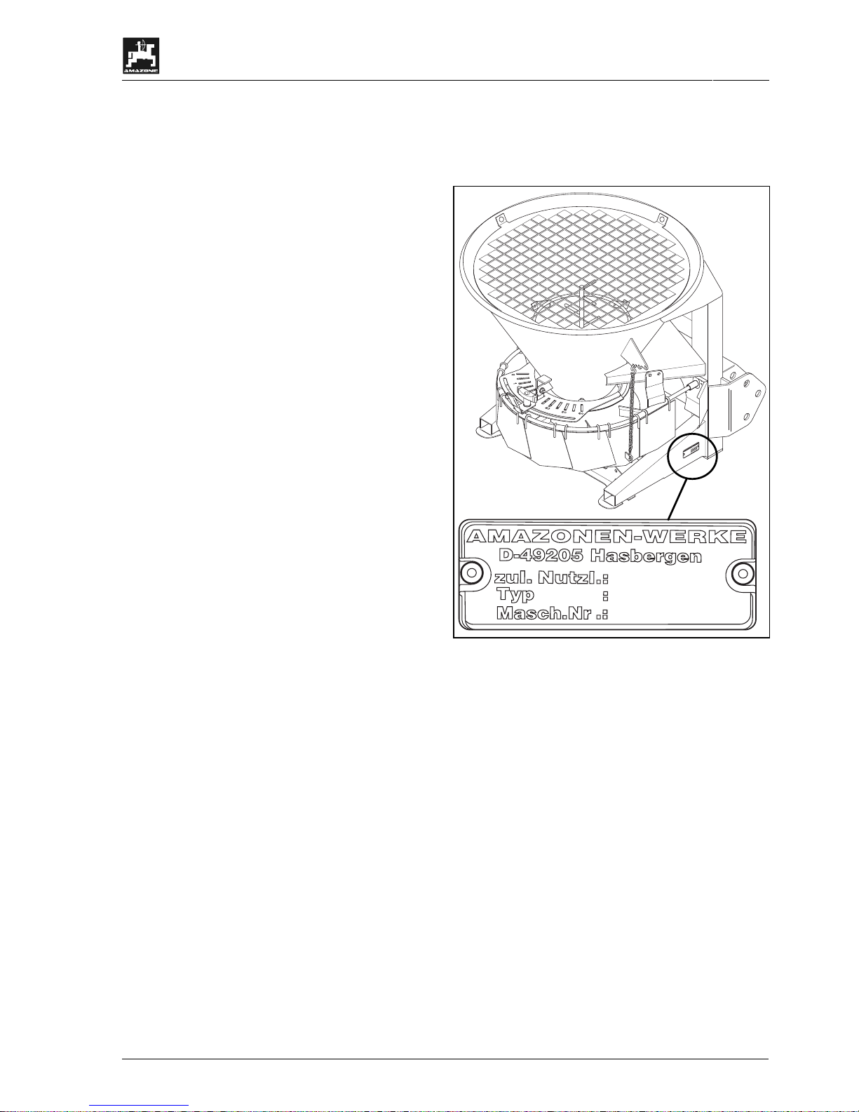
1.5 Type plate
Type plate on the machine.
D
4
9
2
0
5
H
a
s
b
e
r
g
e
n
-
z
u
l
.
N
u
t
z
l
.
:
Ty
p
:
M
a
s
c
h
.
N
r
.
:
F
The entire type plate is of documentary
value and should not be damaged or
removed.
Page 6

6
Details about the machine
DB 534 02. 02
1.6 Technical data
Hopper
capacity
Payload Net weight
Filling
height
Filling
width
Total
length
Total
width
Type
[l] [kg] [kg] [m] [m] [m] [m]
E+S 200
E+S 200 H
150 1000 105 0,86 0,86 1,00 0,95
E+S 300
E+S 300 H
265 1000 111 0,99 1,03 1,18 1,08
E+S 400
E+S 400 H
375 1000 141 1,14 1,19 1,23 1,23
E+S 600
E+S 600 H
620 1000 220 1,30 1,40 1,45 1,45
1.6.1 Operational data
Operational rev. speed of PTO shaft: 540 min-1.
(Please observe the advice in the setting chart).
Max. operational hydraulic pressure: 230 bar.
1.6.2 Hydraulic connections
Required for the hydraulic drive of the spreading
discs (E+S H): 1 single acting spool valve and one
pressure free return flow. The hydraulic shutter
control (special optio n) r equ ires a double acting spool
valve.
1.6.3 Details about noise level
The tractor operator s eat rel ated em iss ion valu e is 7 4
dB (A), measured when operating with shut tractor
cab at the ear of the tractor operator.
Measuring device: OPTAC SLM 5.
The emission value depends on type of vehicle used.
Page 7

Details about the machine
7
DB 534 02. 02
1.7 Designated use of the machine
The designated use for the winter application
spreader AMAZONE E+S is for the exclusive use
only for winter servic e on roa ds and wa ys, etc. and in
road construction for s preading grit and sand on the
base layers and on the upper asphalt base and
wearing layer as well as for s pread ing sand on sports
grounds and golf courses.
Slopes of up to 20% can be spread. On steeper
slopes the spread pattern would become uneven.
Any use beyond these g uidelines stipulat ed above is
no longer considered as designated use. The
manufacturer does not accept any responsibility for
damage resulting from non-com pliance and therefor e
the operator himself carries the full risk.
Under "designated use" also the manufacturer’s
prescribed operation, maintenance and repair
conditions must be adhered to as well as the
exclusive use of original AMAZONE spare parts.
a
Any damage resulting from arbitrary
changes on the machine rule out the
responsibility of the manufacturer.
Though machines having been manufactured with
great care certain deviations cannot totally be
excluded even at a design ated use. T hese de viations
may be caused e.g. by:
- Varying composition of the spread ing material ( e.
g. granule size distribution, specific density,
granule shape).
- Blocking up or bridging (e. g. by foreign particles
or moisture).
- Wear of wearing parts (e.g. spreading vanes,
agitator . . . ) .
- Damage by external influence.
- Wrong drive R.P.M. and travelling spe eds .
Fitting wrong spreading discs (e.g. mixing them up).
- Wrong setting of the machine, nod adhering to
the setting chart).
Therefore, check and ensure that your machine is
functioning correctly before and during use. Claims
regarding damage not having occurred on the
machine itself will be rejected. This also applies for
damage due to spreading errors..
Page 8

8
Safety
DB 534 02. 02
2. Safety
This instruction m anual contains basic advice, which
has to be observed when mounting, operating and
maintaining the machine. Thus, this instruction
manual has implicitly to be read by the operator
before starting to operate and this book must be
made available to him.
All safety advice in this instruction manual must be
strictly observed and adhered to.
2.1 Danger when not adhering to the
safety advice
Not adhering to the safety advice
• may result in endangering persons, also the
environment and also the machine itself.
• may result in the rejection of any claim for
damage.
Not paying attention to the safety ad vice may cause
the following risks:
• Danger to persons not ex cluded from operational
areas.
• Failure of important functions within the machine.
• Failure of carrying out prescribed measures of
maintenance and repair.
• Danger to persons through physical or chemical
contact.
• Danger to p ersons, or the en vironment by leak ing
hydraulic oil.
2.2 Qualification of operator
The implement may only be operated, maintained
and repaired by persons, who are acqu ainted with it
and have been informed of the relevant dangers.
2.3 Identification of advice in this
instruction manual
2.3.1 General danger symbol
The safety advice in this operators manual, which
may lead to a danger to persons if not being
observed, are identified with the general danger
symbol (Danger symbol according to DIN 4844-W9)
a
2.3.2 Attention symbol
Attention symbols which may cause dangers to the
machine and it’s function when not being adhered to,
are identified with the attention symbol.
I
2.3.3 Hint symbol
This symbol marks machine’s specific points that
should be observed to ensure the correct spre ading
operation.
F
.
Page 9
Safety
9
DB 534 02. 02
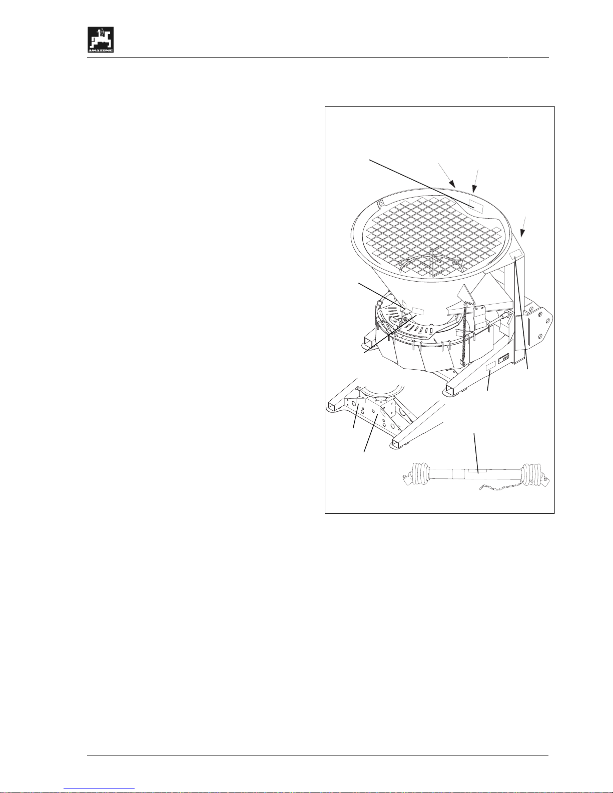
2.3.4 "Attention" pictographs and "advice"
pictographs on the machine
• Attention pictographs indicate dangerous points
on the machine. Observing these pictographs
means safety for all perso ns using this machine.
The attention pictographs always are linked to
safety/warning symbols.
• The advice pictographs mark the machine’s
specific points which have to be observed to
ensure correct spraying operation.
• Strictly observe all warning and advice
pictographs.
• Please pass on all safety advice also to other
users.
• Please always keep all attenti on and advice s igns
clean and in an easily readab le condition. Please
ask for replacement of damaged or missing
decals from your dealer and attach to relevant
place! (picture-No.: = Order-No.)
• The adjacent illustrations show the fixing points of
attention signs and advice signs. Please refer to
the following pages for relevant explanations.
D
4
9
2
0
5
H
a
s
b
e
r
g
e
n
-
z
u
l
.
N
u
t
z
l
.
:
Ty
p
:
M
a
s
c
h
.
N
r
.
:
MD 079
MD 078
MD 089
MD 083
911888
912304
MD 075
MD 095
912336
1480-03-05.01-0
912312
Page 10

10
Safety
DB 534 02. 02
Picture No.: 912 304
I
912 304
Gelenkwellenlänge beachten (sonst Getriebeschaden). Siehe Betriebsanleitung.
Veiller impérativement à la longueur de la transmission (risque
d’endommagement du boîtier). Voir le manuel d’utilisation.
Check correct p.t.o. shaft length (otherwise gearbox damage will result). - see
instruction book.
Geeft aandacht aan de lengte van de aftakas zoals de gebruikshandleiding
aangeeft, anders kan de aandrijfkast beschadigen.
Picture No.: 912 336
I
912 336
Zapfwelle nur bei niedriger Motordrehzahl einkuppeln.
Bei Überlastung schert die Sicherungsschraube ab.
Bei häufigem Abscheren Gelenkwelle mit Reibkupplung einsetzen.
La prise de force ne doit être enclenchée qu’à régime moteur réduit.
En cas de surcharge, la vis de sécurité se casse.
En cas de cisaillement fréquent, utiliser une transmission avec
limiteur de couple à friction.
Engage pto-shaft only at low engine speed.
In case of overstrain the shear bolt shears off.
If shear bolt shears off too frequently we recommend the use
of a pto shaft with friction clutch.
Aftakas alleen bij laag motortoerental inkoppelen.
Bij overbelasting breekt de breekbout af.
Bij dikwijls breken een aftakas met slipkoppeling toepassen.
GB
D
F
NL
D
F
GB
NL
Page 11
Safety
11
DB 534 02. 02
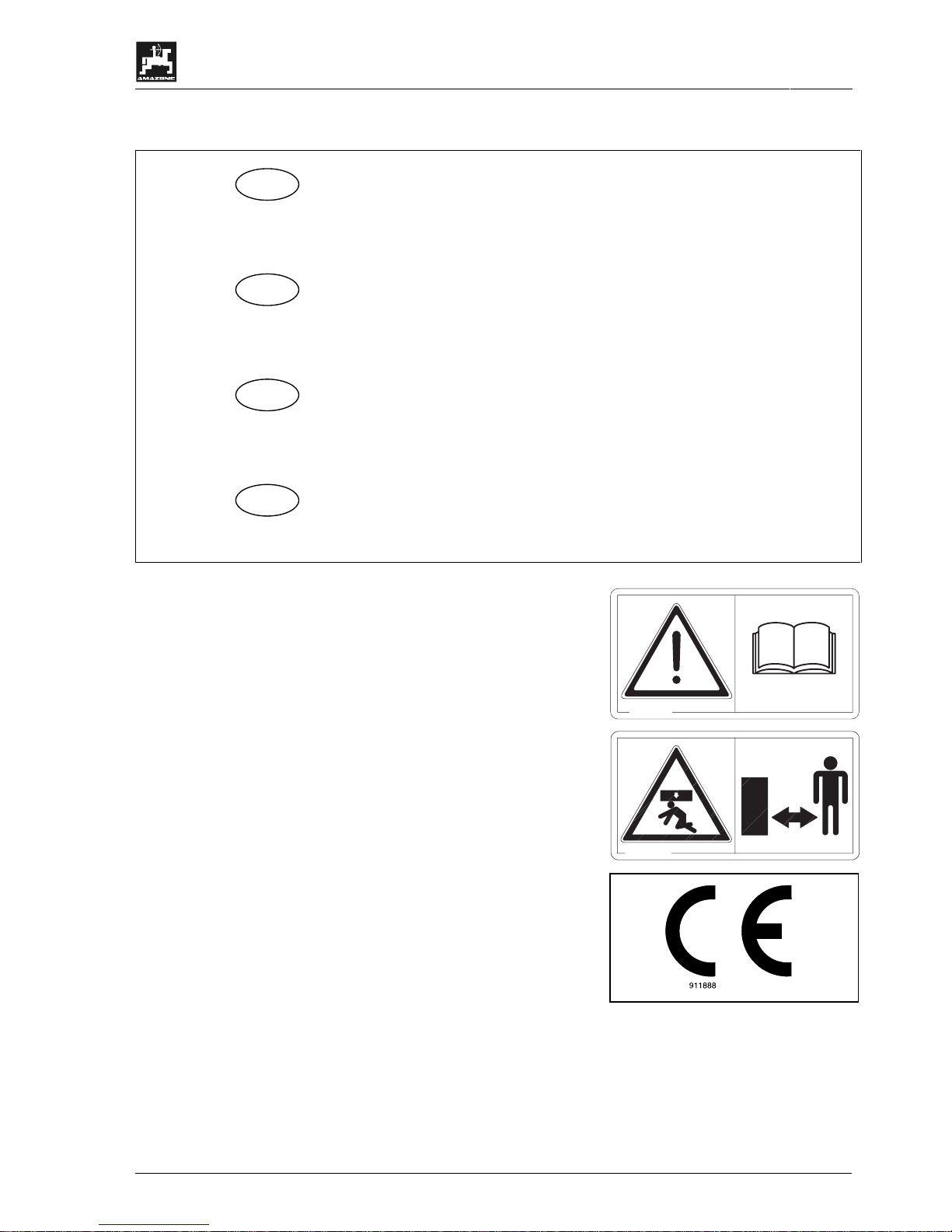
Picture No.: 912 312
I
912 312
1. Vorderachsentlastung des Schleppers beachten.
2. Rührfinger, Auslauföffnungen und Streuschaufeln
sauber und funktionsfähig halten.
1. Veiller à la bonne adhérence de l’essieu avant.
2. Maintenir propres et opérationnels les agitateurs,
les orifices d’alimentation et les aubes.
1. Bear in mind front axle weight reduction.
2. Always keep agitator fingers, outlets and vanes
clean and replace when worn or damaged.
1. Op de vooras ontlasting van de traktor letten.
2. Roerdervingers, uitloop-openingen en
strooischoepen schoon en bedrijfsgereed houden.
Picture No.: MD 095
Explanation:
Before commencing operation read thoroughly
operators manual and safety advice.
MD 095
Picture No.: MD 089
Explanation:
Never stay under a lifted spreader (unsecured load).
MD 089
Picture No.: 911 888
The CE sign indicates that the implem ent fulfils the
requirements of the EC guide line Machine
89/392/EWG and the relevant additional guide lines.
D
F
GB
NL
Page 12
12
Safety
DB 534 02. 02
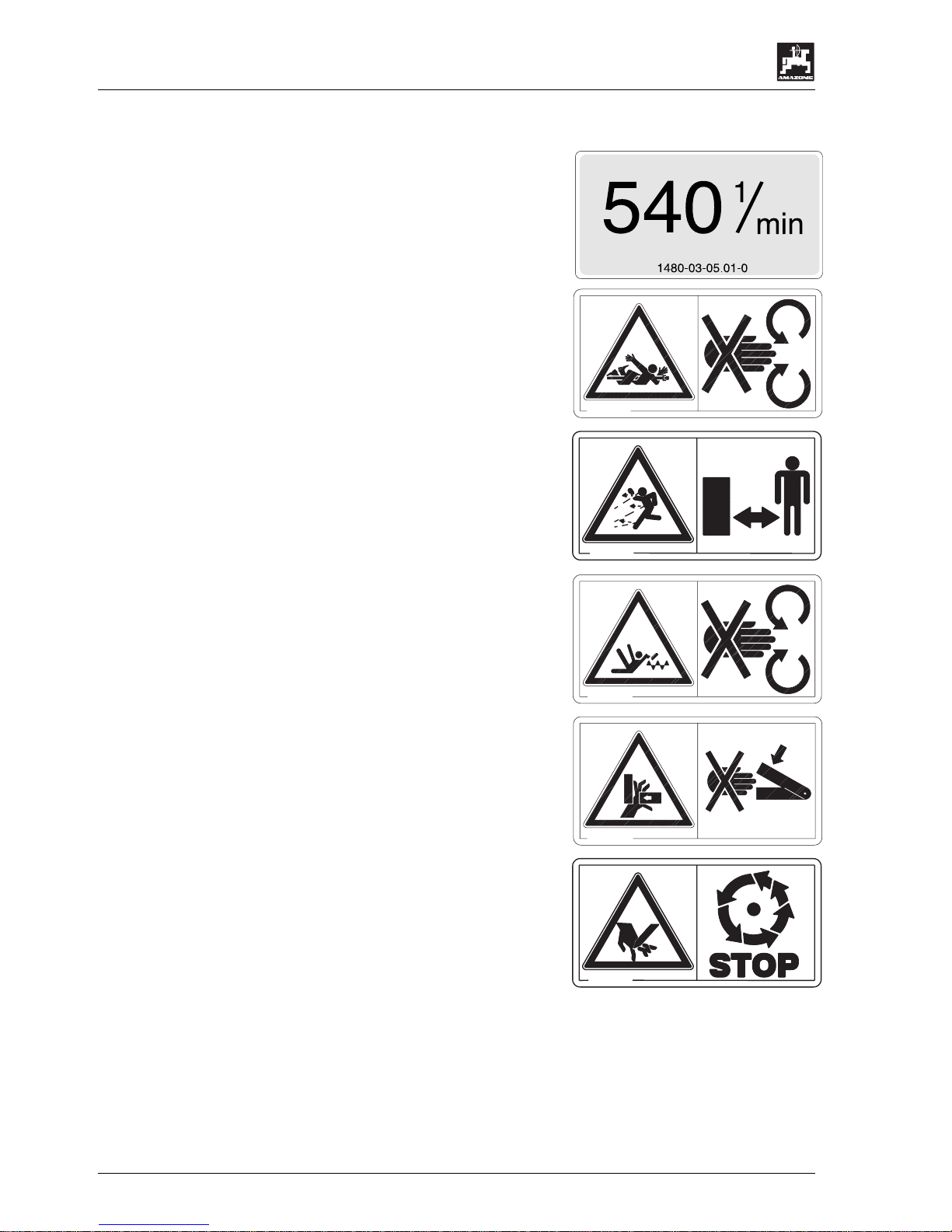
Picture No.: 1480-03-05.01-0
Explanation:
Max. PTO shaft rev. speed 540 1/min.
Picture No.: MD 093
Explanation:
Danger from rotating machine parts.
Never touch rotating shafts, spreading discs, etc.
MD 093
Picture No.: MD 079
Explanation:
Danger because of flinging spreading material
particles.
Advise people to leave the danger area.
MD 079
Picture No.: MD 083
Explanation:
Never reach into the rotating agitator spiral.
MD 083
Picture No.: MD 078
Explanation:
Never reach into the zone of danger of bruising ( e.g.
shutter slides and shutter openings) as long as parts
can still move there.
MD 078
Picture No.: MD 075
Do not stay within the zone of spinning spreading
discs.
Do not touch moving implement parts. Await their
absolute standstill.
MD 075
Page 13

Safety
13
DB 534 02. 02
2.4 Safety conscious operation
Besides the safety advice in this instruction manual
additionally, the national, and generally valid
operation safety and accident prevention advice of
the authorised trade association are binding,
especially UVV 3.1, UVV 3.2 and UVV 3.4.
Adhere to the safety advice on the decals on the
machine.
When travelling on public roads observe the traffic
regulations in force in your country.
2.5 Safety advice for the operator
2.5.1 General safety and accident
prevention advice
Basic principle:
Always check traffic and operational safety before
putting the machine to operation.
1. Adhere to the ge ner a l rul es of hea lth- and safety
precautions besides the advic e in th is instr ucti on
manual.
2. The fitted warning- and advising decals give
important hints for a s afe operation; adhering to
them protects your own safety.
3. When making use of public roads adhere to
applicable traffic rules.
4. Become acquainte d with the machines controls
and functions before beginning the operation.
Doing this during operation would be too late.
5. Avoid wearing any loose clothing that would
possibly wrap or catch on moving machinery.
6. Avoid danger of fire by keeping the machine
clean.
7. Before beginning to move, check surrounding
area (children etc.). Ensure suff icient v isib il ity.
8. Sitting or standing on the implement during
operation or during transport is not permissible.
9. Attach implements as advised and only to the
advised devices.
10. Special care should be taken when the
implement is coupled to or off the tractor.
11. When attaching or removing the m achine bring
any parking or storing devices into the
corresponding position (standing safety).
12. Fit weights always to the fixin g points provided
and as advised for that purpose.
13. Adhere to the maximum perm issible axle lo ads,
total weights and transport dimensions.
14. Observe the outer permissible transport
dimensions according to your national traffic
law.
15. Fit and check transport gear, traffic lights,
warnings and guards.
16. T he release ropes for quick coupling three point
linkages should hang freely and in the lowered
position must not release by themselves.
17. During driving never leave the operator’s seat.
18. Mount the implement as prescribed. Moving
behaviour, steerability and braking are
influenced by mounted im plements, trailers and
ballast weights. Check sufficient steerabil ity and
braking.
19. When lifting a three-point-implement the front
axle load of the tractor is reduced dep ending on
its size. The sufficient front axle load (20% of the
tractor net weight) must be observed (pls.see
instruction book of the vehicle manufacturer).
20. When driving into bends m ind the projection to
the sides and the gyrating mass of the
implement.
To avoid sidewa ys swing of the s preader during
operation stabilise the lower link arms of the
three-point-hydraulic.
21. Take implement only into operation when all
guards are fixed in position.
22. Never stay or let anyone stay within the
operation area of the implement.
23. Hydraulic folding frames may only be actuated
when nobody is staying in the swivelling range.
24. On all hydraulically actuated pivoting parts
exists danger of injury by bruising and trapping.
25. On all hydraulically actuated pivoting parts
exists danger of injury by bruising and trapping.
26. Before leaving the vehicle lower the implement
to the ground. Actuate t he parking brakes, stop
the engine and remove ignition key.
27. Nobody should stay between vehicle and
implement if the tractor is not secured against
rolling away by the parking brake and/or by
chocks.
28. Note maximum permissible filling loads.
Bear in mind the spreading material bulk
density [kg/l].
Payload
E+S 200 1000 kg
E+S 300 1000 kg
E+S 400 1000 kg
E+S 600 1000 kg
29. Do not place any foreign objects inside the
hopper.
30. During the calibrat ion test watch out for danger
zones due to rotating implement parts.
31. Never park or mov e the spreader with filled
hopper (danger of tipping over).
32. Before any operation check perfect seat of
the fixing parts, especially for spreading
disc- and spreading vane-fixing.
Page 14

14
Safety
DB 534 02. 02
2.5.2 General safety and accident
prevention advice for mounted
implements
1. Before mountin g and dismounting implem ents to
the three-point link age bring all control lever s in
such a position that an unintended lifting or
lowering is impossible.
2. When fitting to the three-point linkage the
mounting categories on the vehicle and the
implement must coincide.
3. Within the range of the three-p o int li nkage danger
of bruising and shearing.
4. When actuating the control levers for the three-
point linkage never step between vehicle and
implement.
5. In transport position of the implement always take
care for a sufficient lateral locking of the three
point.
6. When driving on public roads with lifted
implement the control lever has to be locked
against unintended lowering.
7. Mount and dismount implements as prescribed.
Observe manufacturer’s advice.
8. Working implements should only be transported
and driven on vehicles which are designed to do
this.
2.5.3 General safety and accident
prevention advice when operating
with PTO shafts
1. Use only PTO shaf ts which are designed for the
implement by the manufacturer and which are
equipped with all legally reques ted guards .
2. Guard tubes and cones of the PTO s haft as well
as a vehicle and implement s ide PT O guard m us t
be fitted and kept in a proper condition.
3. On PTO shafts always ensure the tube has
sufficient overlap in transport- and operating
position. (Observe instruction m anual of the PTO
shaft manufacturer.)
4. Fit and remove the PTO shaft only when the
universal joint shaft is diseng aged and when the
engine is stopped and ignition key is removed.
5. Ascertain correct fitting and sec uring of the PT O
support.
6. Prevent PTO guard from spinning by fixing the
provided chain to a nearby static part.
7. Before switching on the PTO shaft ensure that
the chosen PTO speed of the tractor corresponds
to the allowable implement input speed. Usually
the PTO shaft speed is 540 R.P.M. (please
observe data in the setting chart).
8. Slow engagement of the PTO shaft protects
vehicle and spreader.
9. When using the ground-related PTO take into
account that the PTO speed depends on the
driving speed and that the turning direction is
reversed when driving backwards.
10. Before switching on the PTO shaf t take care that
no one stays in the danger zone of the
implement.
11. Never switch on the tr actor PTO while engine is
stopped.
12. When operating with a switched on PTO shaft
allow no one to sta y near to the spinni ng PTO or
universal joint shaft.
13. Alwa ys stop PTO when it is n ot needed or whe n
the shaft is in an adverse pos ition. D isen gage th e
universal joint shaft as soon as the outlet
openings are closed.
14. Attention! After switching off the PTO the
mounted implement may continue to run by its
dynamic mass.
During this period never come too close to the
implement. Begin to work on the implement only
after it has come to a full standstill.
15. Clean and grease the universal joint shaft and
the PTO driven implement only after the PTO
shaft and engine have been stopped an d ignition
key pulled out.
16. Place the uncoupled PTO shaft on the retaining
support provided.
17. After removal of PTO shaft apply guard cap o nto
PTO stub.
18. Imm ediately repair any damage before operat ion
to avoid consequential problems.
2.5.4 General safety and accident
prevention advice for the hydraulic
system
1. The hydraulic system is under high pressure.
2. Connect hydraulic hoses to the hydraulic rams
and motors according to the advice in the
instructions.
3. When fitting the hydraulic hoses to the vehicle
hydraulic sockets always ensure that the
hydraulic system on the vehicle as well as on the
implement is without pressure.
4. To avoid wrong hydraulic connection between
vehicle and implem ent, sock ets and plugs sho uld
be marked (e. g. colour coded). This helps to
prevent contrary function (lifting instead of
lowering or vice versa) and reduces th e da nger of
accident!
5. All hydraulic hoses must be checked for their
operational safet y by a skilled person before the
first operation of the machine and then at least
once a year. In case of damage or ageing
replace the hydraulic hoses! The replacement
hoses must corres pond to the tec hnical d emands
of the implement manufacturer.
6. When searching for leaks appropriate aids sh ou ld
be used because of the danger of injury.
7. Liquids leaking under high pressure (hydraulic
oil) can penetrate the skin and cause severe
injury. When injured see a doctor immediately!
Danger of infection.
Page 15

Safety
15
DB 534 02. 02
8. Before s tarting to do repair work to the h ydraulic
system release the pressure by actuating the
control lever accordingly, lower machine to the
ground and stop vehicle engine.
9. The period of use of any hose circuit should not
exceed six years including a possible storing
period of two years max imum. Also when stored
and used properly hoses and hose circuits do
age. Therefore their longevity and period of use
is limited. Deviations from the above may be
accepted by the Health- and Safety Authorities
depending on the experience the y have had and
the danger potential. For hoses and hose circuits
made of thermoplasts other guide lines may
prevail.
Page 16

16
Safety
DB 534 02. 02
2.6 General safety and accident
prevention advice for maintenance, repair and cleaning
1. Repair-, maintenance- and cleaning operations
as well as the remed y of function faults should
principally be conducted with drive and engine
stopped. Remove ignition key.
2. Chec k nuts and bolts f or tightness regu larly. For
the first time after 3 – 4 hopper fillings. If
necessary retighten nuts and bolts.
3. When doing maintenance work on the lifted
implement make sure that it is secured by
proper supports.
4. Dispose of oil, grese and filters in the
appropriate manner.
5. Before doing any repair work on the electric
disconnect power supply.
6. Before conducting electric welding operations on
vehicle or on the mounted implement, remove
cable from generator and battery.
7. An y spare parts fitted m ust, as a m inimum meet
with the implement manufacturers' fixed
technical standards. Using original AMAZONE
spare parts for example ensures this. Non
original parts invalidate warranty and contravene
these documentation for safe use.
Page 17
Description of product
17
DB 534 02. 02
3. Description of product
The winter application spreader has been designed
for the rear 3-point linkage (cat. II) of a towing
vehicle.
The spreading discs are driven either by the PTO
shaft or a hydraulic motor.
D
4
9
2
0
5
H
a
s
b
e
r
g
e
n
-
z
u
l
.N
u
t
z
l
.
:
Ty
p
:
M
a
s
c
h
.
N
r
.
:
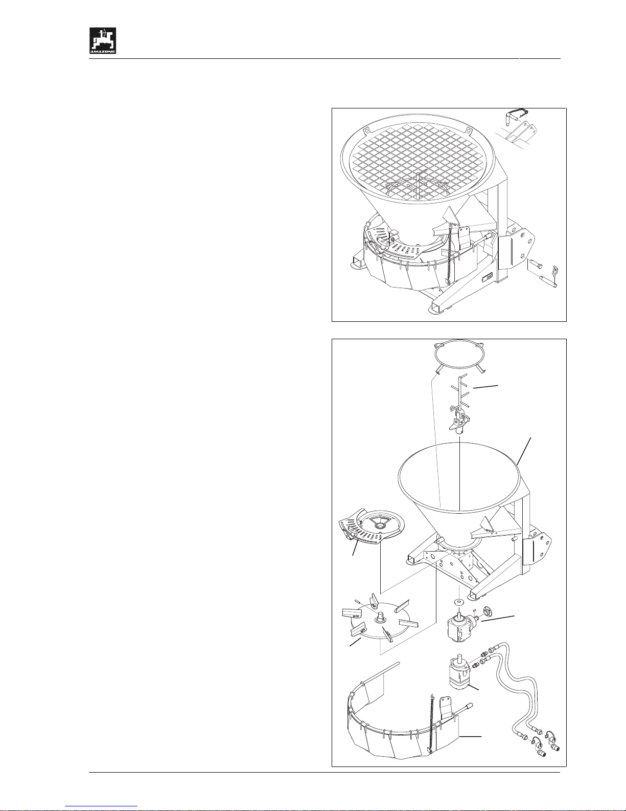
The spreader consists of the five components:
• Frame and hopper (1).
• Bottom group (2).
• Gearbox (3) or hydraulic m otor (4) with spreading
disc (5).
• Agitator (6).
• multiple spread width reducer (7).
The spreader is as standard equipped with:
• Tractor-3-point linkage cat. I and II..
• Drive via Walterscheid PTO shaft (E+S) or
hydraulic motor (E+S H).
• Pre-selection switch for spread rate setting.
• Guard screen.
• Agitator.
1
2
3
7
4
5
6
Page 18
18
Description of product
DB 534 02. 02
3.1 Function
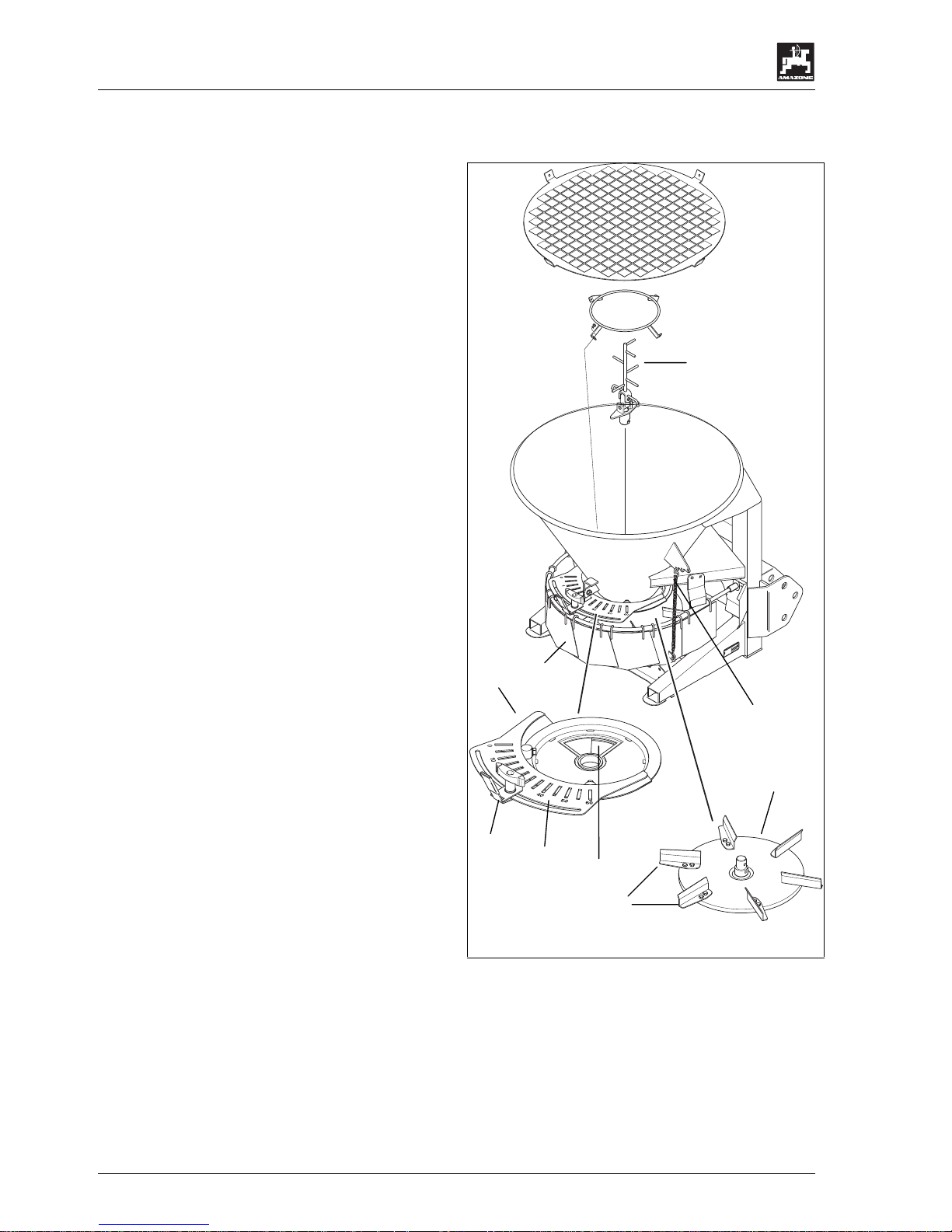
The spreading mater ial slides down t he hopper walls
to the discharge opening (1) i n the bottom group (2).
The agitator (3) prov ides an even spreadin g material
flow on to the spreading disc.
The spreading disc (4) rotates in clock wise direction
an is provided with 6 spreading vanes (5).
Setting the various spreading widths is done via the
multiple spread width reducer (6). Depending on
the kind of spreading material working widths of
between 1 and 6 m are settable.
The spread width reducer is adjusted via the chain
suspension (7) according to experience values.
Lifting the spread width reducer – increase of
working width.
Lowering the spread width reducer – reduction of
working width
The spread fan prov ided by the spreading disc can
be moved by twisting the bottom group along the
scale (8).
The shutter (9) allows the op ening and closing of the
discharge opening (1) as well as the spread rate
setting.
To close the discharge opening move the shutter
(1) to scale figure "0" on the sc ale (8) and lock in this
position.
Read the shutter position for spread rate setting
off the scale (8). The necessary shutter position is
determined either by experience values or can be
taken from the setting chart.
D
4
9
2
0
5
H
a
s
b
e
r
g
e
n
-
z
u
l
.
N
u
t
z
l
.
:
Ty
p
:
M
a
s
c
h
.
N
r
.
:
1
2
3
4
5
6
7
8
9
Page 19
On receipt of the machine
19
DB 534 02. 02
4. On receipt of the machine
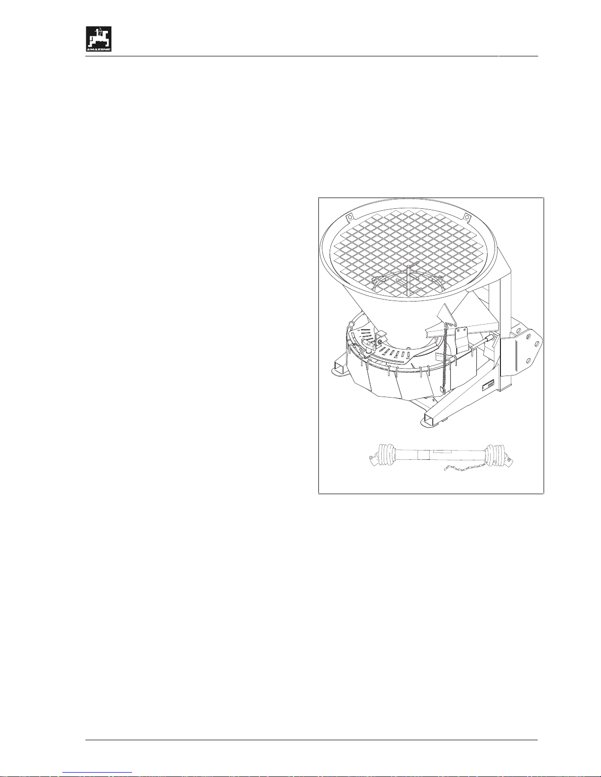
The spreader (1) is supplied with PTO shaft (2).
Check that no damage has been caused in transit
and all parts are present according to the delivery
note.
4.1 Function control
Carry out a function control after receipt of the
machine (1).
For checking the function turn the machine (1) by
hand one time on the gearbox input shaft.
Check lubrication of the PTO shaft (2) and the oil
level in the gearbox (please refer to chapter 6.3.3).
D
4
9
2
0
5
H
a
s
b
e
rg
e
n
-
zul.Nutzl.:
Typ:
M
a
s
c
h
.
N
r
.
:
Page 20
20
On receipt of the machine
DB 534 02. 02
4.2 PTO shaft drive
The reduction gear (i = 1:2) for the spreading disc
and the agitator is driven v ia the PT O shaft. W ith this
gearbox the spreading disc re v. speed is approx . 270
min
-1
at a PTO shaft rev. speed of 540 min-1.
4.3 Fitting the PTO shaft
a
Danger of tipping over.
Assemble centrifugal broadcasters only
with empty hopper.
I
Only use the PTO shaft prescribed by
the manufacturer. Walterscheid-PTO
shaft (W100E-SD05-710).
I
Observe the instruction manual of the
PTO shaft manufacturer.
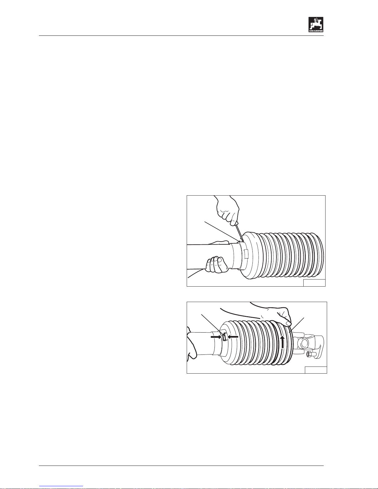
Remove the PTO shaf t guard on the implem ent side
PTO shaft half:
- Tilt machine to the rear.
- Remove fixing bolt (1) n.
ZA 013a
- Twist cone (1) into fitting position (2).
ZA 014a
1
1
2
Page 21
On receipt of the machine
21
DB 534 02. 02
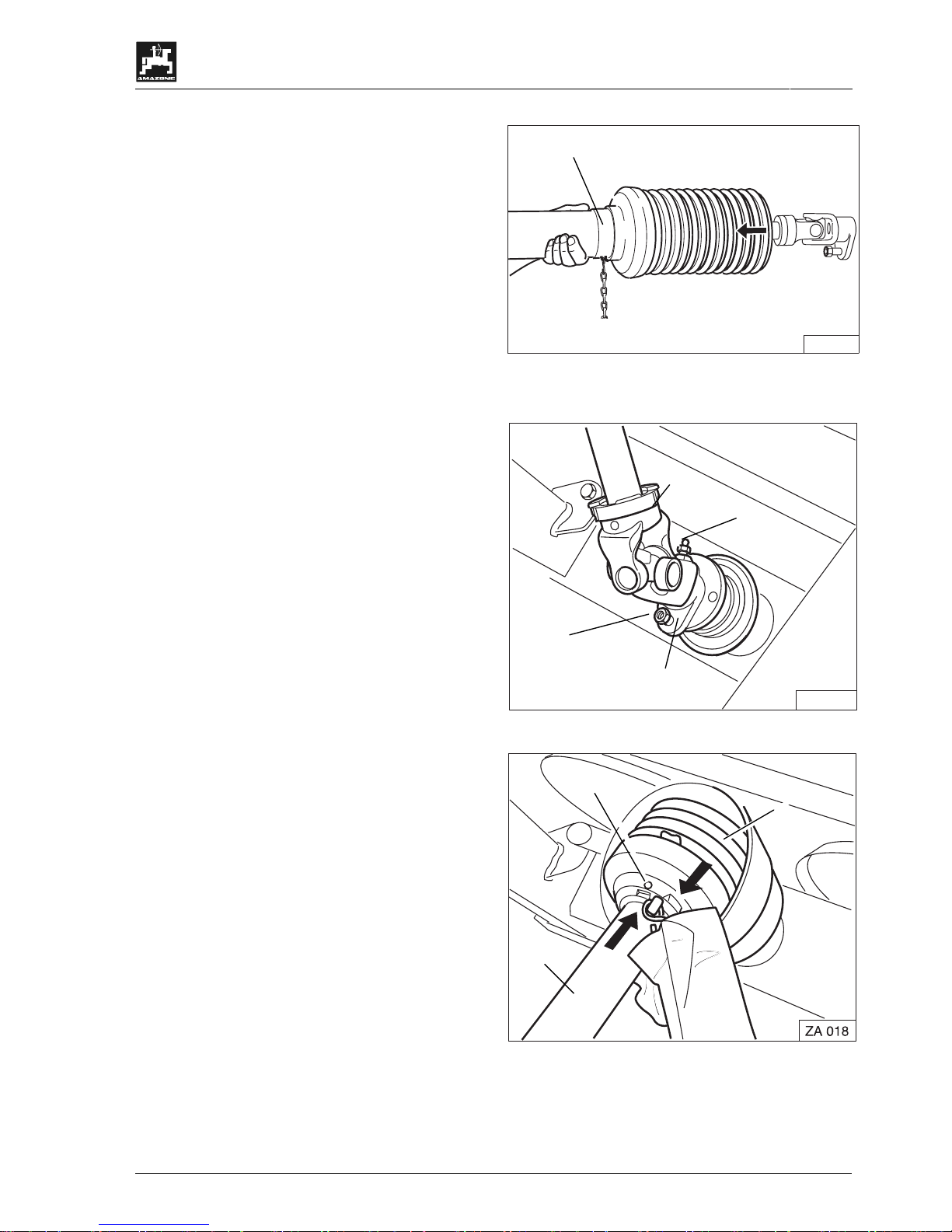
- Pull off protective half.
ZA 015a
I
Before fitting the PTO shaft clean and
grease the gearbox input shaft
- Slacken greasing nipple (1)
- Apply PTO shaft (2).
- Affix connecting yoke (3) with shear bolt (4).
- Screw in grease nipple (1).
ZA 016a
Assembly of PTO shaft guard:
- Push on guard half (1).
- Twist guard cone (2) into fitting position.
- Screw in locking bolt (3).
- Tilt machine to the front.
- Apply second PTO shaft half and affix in the
upper link bracket.
- Secure the guard tube on the frame by using a
chain.
1
2
1
3
4
2
3
1
Page 22
22
On receipt of the machine
DB 534 02. 02
4.4 Hydraulic drive
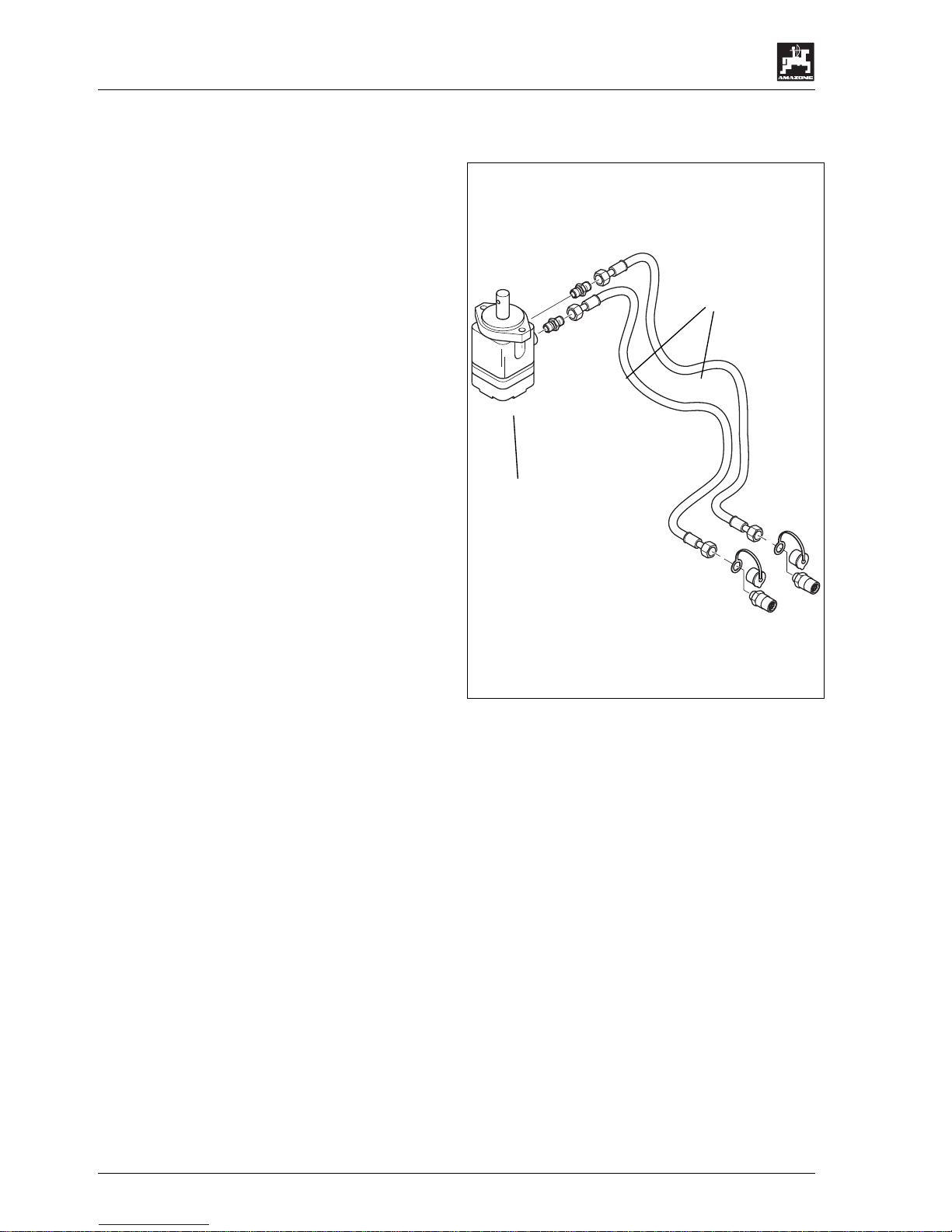
The spreading disc and the agitator are driven v ia the
hydraulic motor (1). This requires on the towing
vehicle:
• 1 single acting spool valve
• 1 pressure free oil return flow.
• A pump capacity on the towing vehicle of min.
26 l/min. to max. 45 l/min.
I
The indicated required pump capacities
result in a spreading disc rev. speed of
min. 250 min
-1
to max. 400 min-1.
F
If the pump capacity is within the upper
range, operate with a reduced engine
nominal rev. speed of the towing vehicle
and thus with a reduced pump capacity.
This measure results in less wear on
agitator and hopper bottom, especially
when spreading grit.
• Hydraulic hoses (2)
(Length 1,60 m)
- The "flow hose" is equipped with a yellow
galvanised plug (hard pressure spring on the
plug)
- "Return flow" with silver galvanised plug (soft
pressure spring in the plug) and return valve.
1
2
Page 23

Mounting and dismounting
23
DB 534 02. 02
5. Mounting and dismounting
a
Danger of tipping over.
For mounting and dismounting place the
spreader on level ground. Don’t lift at the
front.
a
Danger of tipping over!
Mount and dismount the spreader only
with an empty hopper.
a
Any operation on the spreader should
only be carried out with switched off
motor and pressure-free hydraulic
system.
a
Remove ignition key. Secure the vehicl e
against unintended starting and rolling
away.
a
Danger of tipping over
Advise people to leave the danger area
behind and underneath the machine.
a
Danger of tipping over
When linking up observe sufficient
space for movement of the lower links.
a
Danger of tipping over.
Lift machine only with attached upper
link.
a
The speed of lowering the filled spreader
must never be faster than 2 seconds. If
available set the throttle valve
accordingly.
I
Ensure a horizontal and lateral stable
mounting cross ways to the driving
direction to prevent the machine from
swinging to and fro during spreading
operation.
Page 24
24
Mounting and dismounting
DB 534 02. 02
5.1 Mounting
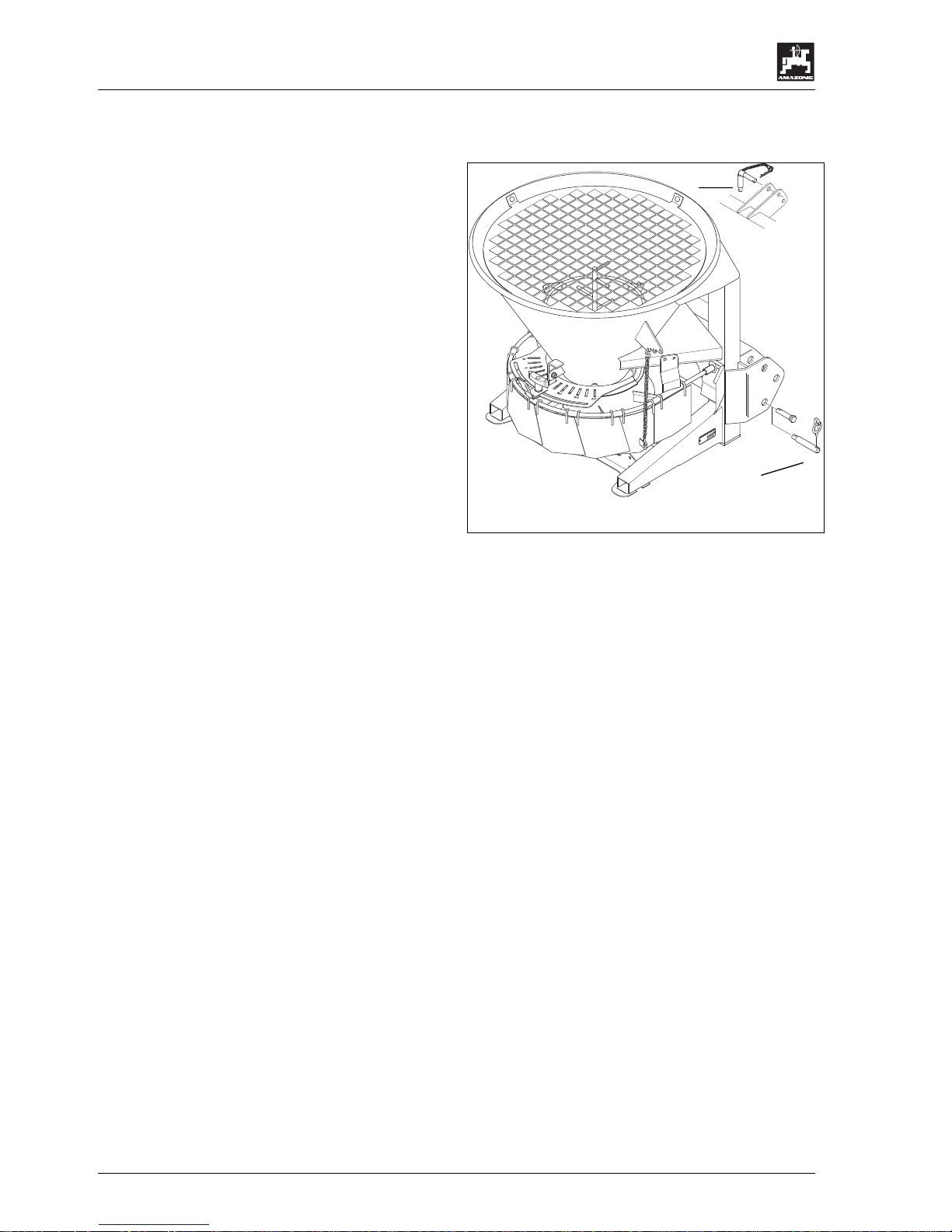
Mount the spreader to the r ear three point hydraulic
cat. I or II or to a special fittin g device on the towing
vehicle (please refer to chapter 2.5.
2.
- Push lower link of the towing vehicle or of the
fitting device on to th e lower li nk pins (cat. I or II)
(1) and secure by using a clip pin.
- Fix upper link with fixing (Kat. I or II) (2) and
secure.
D
49205
Hasbergen
-
z
u
l
.
N
u
t
z
l
.
:
Ty
p
:
M
a
s
c
h
.
N
r
.
:
a
Never fix upper link of cat. II with pin of
cat. I.
a
Advise people to leave the danger area
behind or underneath the implement
while carrying out settings on the upper
linkage.
a
In lifted position of the spreader the
lower link arms of the tractor ma y have
only little lateral play so that the
implement does not swing to and fro
during spreading operation. Secure the
lower link arms of the tractor with
stabilising rods or chains.
5.1.1 E+S with PTO shaft
- Push the PTO shaft on to the tractor universal
joint shaft.
a
Ensure a proper catching of the PTO
shaft connection.
I
When initially fitted and when changing
the vehicle type match PTO shaft (for
this, please refer to para. 5.3).
- Hook in fixing chains of the PT O shaft guard on
towing vehicle and implement side so that a
sufficient swivel range of the PTO shaft in all
operating positions is e nsured and that the PTO
shaft guard does not spin during operation.
I
On towing vehicle and implement only
use PTO shaft with complete guard and
additional guard fitted. Replace guards
immediately once they have been
damaged.
1
2
Page 25

Mounting and dismounting
25
DB 534 02. 02
5.1.2 E+S with hydraulic motor
a
The hydraulic system is under high
pressure.
Connect hydraulic hoses to the
hydraulic rams and motors according to
the advice in the instructions.
When fitting the hydraulic hoses to the
vehicle hydraulic sockets always ensure
that the hydraulic system on the vehicle
as well as on the implement is without
pressure.
- Connect the oil return f low hose with a press ure
free oil return flow.
F
The oil return flow hose is provided with
a silver galvanised plug, soft pressure
spring on the plug and a return valve.
- Connect the flow hose with a single acting spool
valve.
F
The "flow hose" is provided with a
yellow galvanised plug and hard
pressure spring on the plug.
F
The spreading disc rotates in clockw ise
direction.
I
In case of a wrong direction of rotation
re-bolt or exchange the hoses
on the motor,
on the towing vehicle or
on both of them.
5.2 Dismounting
- For dismounting place the spreader with empty
hopper on a level ground s o that ther e is no n eed
to lift the machine at the front ( danger of tipping
over).
- Dismount the spreader from the towing vehicle.
- (E+S) Fix PTO shaft with the upper link pin in the
upper link shackle.
- (E+SH) Place couplings for the hydraulic hoses in
the provided retainers.
Page 26
26
Mounting and dismounting
DB 534 02. 02
5.3 Initial fitting and matching up
of the PTO shaft
When initiall y fitting, match PTO shaft to the vehicle.
As this matching onl y applies for this s pecific vehicl e
type, check or repeat PTO shaft matching when
changing vehicles.
I
Observe the instruction manual of the
PTO shaft manufacturer.
- Pull apart the PTO shaft halves.
- Fit PTO shaft half to the vehicle side.
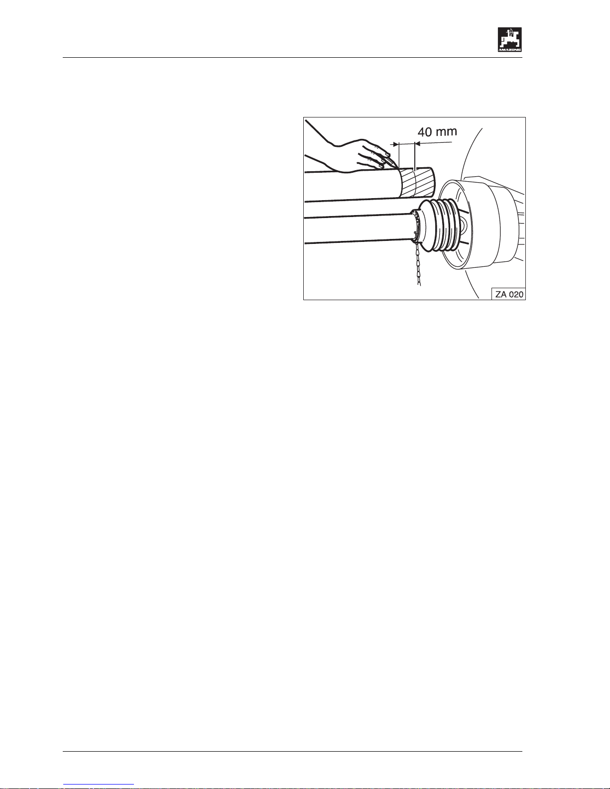
- Hold the PTO shaft halves (1) and (2) in their
shortest and longest op erational position side by
side and check the overlap of the PTO shaft
tubes.
-In shortest position the universal joint shaft
tubes must never hit the univ ersal yokes . Allo w a
safety spacing of at least 40 mm.
- In the longest operational position the PTO
shaft tube overlapping prescribed by the PTO
shaft manufacturer has to be observed (please
refer to the instruction m anual of the PTO shaft
manufacturer).
- For matching the length of the PT O shaft halves
hold them side by side in the c losest operational
position, mark and shorten according to
indication of the PTO shaft manufacturer.
- Insert PTO shaft halves into one another.
- Push PTO shaft on the vehicle’s universal joint
shaft.
a
Ensure a proper catching of the PTO
shaft connection.
- Hook in fixing chains of the PTO shaft guard on
towing vehicle and implement side so that a
sufficient swivel range of the PTO shaft in all
operating positions is ensured and that the PTO
shaft guard does not spin during operation.
a
On towing vehicle and implement only
use PTO shaft with complete guard and
additional guard fitted. Replace guards
immediately once they have been
damaged.
Page 27

Transport on public roads
27
DB 534 02. 02
6. Transport on public roads
a
For travelling on public roads with the
spreader mounting to a towing vehicle
observe the traffic regulations in force in
your country.
a
Vehicle owners as well as t he operators
are responsible for adhering to the legal
traffic regulations of their country
According to the harmonised European traffic
regulations traffic lights and warning plates are
required on spreaders m ounted to a towing vehicle.
These regulations read as follows:
- If the prescribed rear lights, the direction
indicators or the registration No. of the towing
vehicle are hidden by the spreader (or other
implement) they will h ave to be repeated on t he
mounted implement. If the sides of the mounted
implements protrude more than 400 mm the
outer edge of the light emitting source of the
limiting or tail lights of the towing vehicle, extra
parking warning plates and limiting lights are
required. If the mounted implement protrudes
more than 1 m beyond the ta il ligh ts of the to wing
vehicle parking warning plates, rear light units
and rear reflectors are required. The light units
and possibly required par king warnin g plates and
foils can be obtained from your dealer directly. As
always the latest edition of the national traffic
regulations is valid, please verify them at your
local traffic office.
a
The traffic light kit has to correspond to
the requirements of your national traffic
law..
I
Check proper function of traffic light kit.
a
For travelling on public roads secure the
implement against unintended lowering.
Page 28

28
Putting into operation
DB 534 02. 02
7. Putting into operation
I
The max. angling of the PTO shaft cross
joint must not exceed 25°.
I
Always switch off the pto shaft in case
of too large angling or when it is not
used.
I
To avoid damage engage pto shaft or
hydraulic drive only at slow tractor
engine speed.
7.1 Filling the spreader
I
Before filling the hopper make sure that
no residue or foreign particles are in the
hopper.
I
Observe the permissible payload. Bear
in mind the specific bulk density [kg/l].
Depending on the condition of the
spreading material (moist or dry) other
specific weights may occur.
F
Before filling check the specific weight
of your spreading material. Weigh
accurately 1 litre spreading material. T he
weight is the specific weight [kg/l].
a
Observe the maximum payload and
permissible axle loads and the
permissible total weight of the towing
vehicle. If necessary travel on public
roads with only half filled hopper.
a
Moving characteristics, steering and
braking ability are affected by mounted
implements, trailers or ballast weights.
Therefore, take account to these effects
and allow sufficient steering and
braking.
a
Therefore, when filling the spreader
observe that the required towing vehicle
front axle load is maintained (20 % of t he
vehicle's empty weight, however, also
refer to the instruction manual of the
vehicle manufacturer).
I
To avoid a grinding of the spreading
material and thus an increased wear of
the agitator and the float hopper bottom
open the shutters wide enough so that
an unhindered flow of the spreading
material is ensured (especially impo rtant
with grit).
I
Spreading material which has frozen
over night may cause damage on the
agitating device when switching on the
spreading disc drive.
Page 29
Putting into operation
29
DB 534 02. 02
7.2 Setting the mounting height
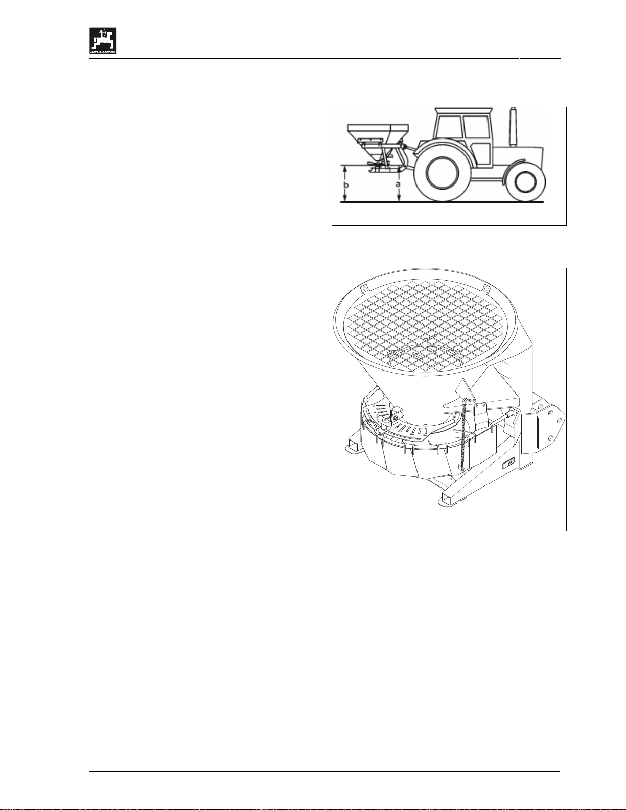
Set the mounting height of the spreader with filled
hopper on to 60 cm (up to 4 m working width)..
Measure on the spreading disc front side (a = 60) and rear side (b = 60) from ground
surface.
7.3 Setting the working width
Working widths of between 1 m and 6 m can be set,
depending on the kind of spreading m aterial. For this
the multiple spreading width reducer (1) is adjusted
via the chain suspension (2) according to experience
values.
I
No accurate spread pattern will be
achieved with damaged or bent
spreading width reducer elements.
Please also refer to para. 7.4 "Swive lling the spread
fan".
D
49205
H
asb
ergen
-
zul.Nutzl.:
Typ:
M
a
s
c
h
.
N
r.:
7.3.1 Checking the spreading width
Check the set working width with the aid of
• a yard stick or
• by sight.
If the actual and the required working width do not
coincide, re-adjust the selected working width setting.
Correction of working width setting:
1. Increasing the working width
- Lif t the spread wid th reducer b y shortening the
chain.
- Increase the drive speed of the spreading discs
depending on the spreading material.
-
2. Reducing the working width
- Lower the working width reducer by extending
the chain.
- Reduc e the drive speed of the spreading discs
depending on the spreading material.
Page 30
30
Putting into operation
DB 534 02. 02
7.4 Swivelling the spread fan
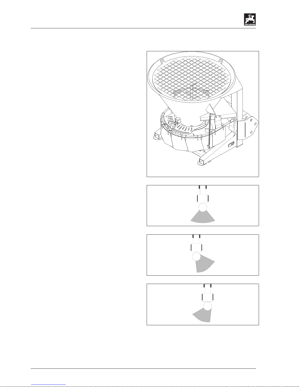
The material spread from the spreading discs forms
the spread fan which can be s wivelle d by twis ting the
bottom group (1) within the range of the scale (2).
The spread fan created by the
Procedure:
- Lift the bottom group loc king ratc het (4) and twist
the bottom group (1) eit her in clockwis e direction
or counter clockwise.
- Lower the bottom group locking ratchet (4) in
order to lock the bottom group (1) in this new
position.
D
49205
H
asb
ergen
-
zul.Nutzl.:
Typ:
M
a
s
c
h
.
N
r.:
Way of function:
• If the bottom group has been set to the scale
figure "30" ((neutral position) the spreading disc
creates a spreading material dependent
symmetric spread fan towards the implements
longitudinal axle.
• If the bottom group is twisted in direction of the
scale figure "0" (clockwise) the spreading disc
creates a spread fan which is moved to the right
hand side in relation to the implement’s
longitudinal axle (seen in driving direction).
• If the bottom group is twisted in the direction of
the scale figure "6 0", the spread ing disc creates a
spread fan which is moved to the left hand s ide in
relation to the implem ent’s longitudinal axle (seen
in driving direction).
Page 31
Putting into operation
31
DB 534 02. 02
7.5 Setting the spread rate
The shutter slide position depends on:
• the kind of spreading material (sand salt or
mixture) and its characteristics (granular,
coarse/fine, moist, dry).
• the desired spreading width [m].
• the intended operational speed [km/h].
• the desired spread rate [g/m²].
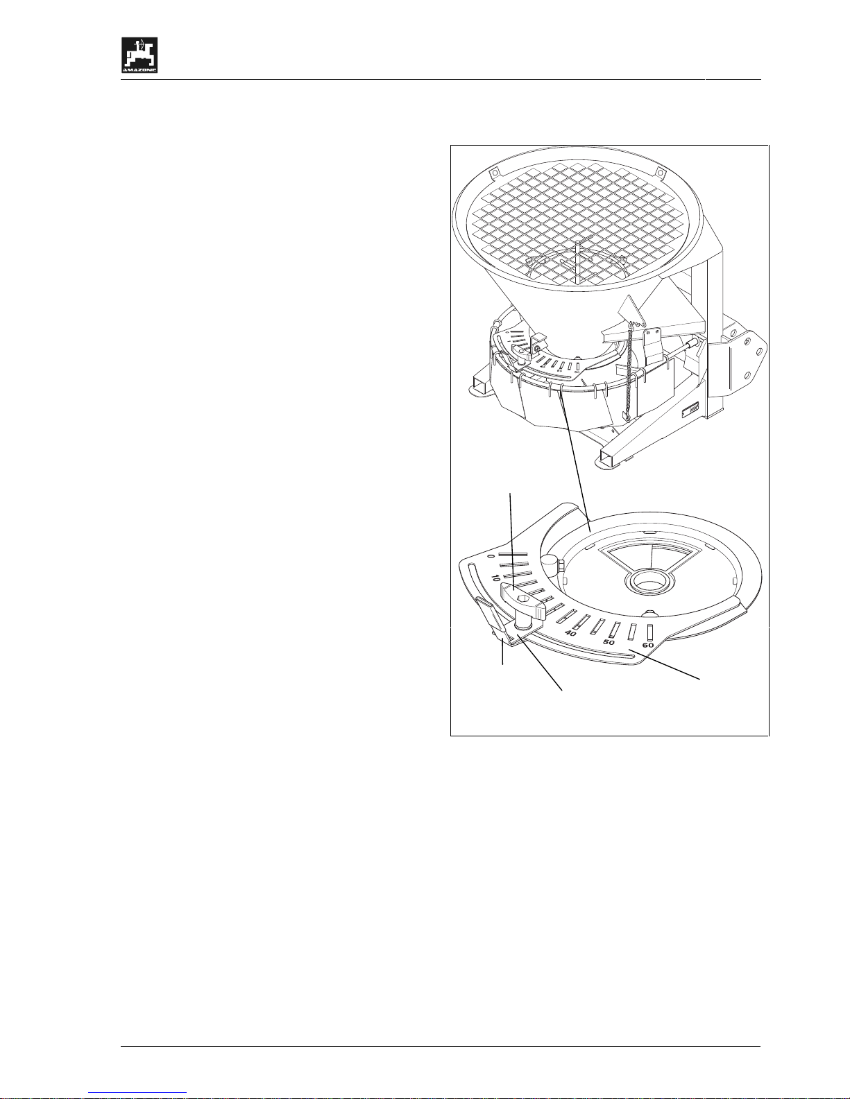
The spread rate is set by moving the shutter slide
lock (1) of the shutter (2) along the scale (3)
according to experience values or according to the
indications given in the E + S set ti ng ch art. This way
different opening diam eters of the discharge opening
can be set.
Moving the shutter slide lock to a higher figure of
the scale (3) means:
• larger opening diameter of the discharge
openings.
• increased spread rate.
F
As the spreading properties of the
spreading materials may heavily vary
(e.g. moist or dry) we recommend that
you determine the desired shutter
position for the desired spread rate with
the aid of a spread rate check.
Procedure of spread rate setting:
- Slacken the thumb nut (4) .
- Set the pointer of the shutter slide lock (1) onto
the desired figure on the scale (3).
- Retighten thumb nut (4) firmly.
D
49205
H
asb
ergen
-
zul.Nutzl.:
Typ:
M
a
s
c
h
.
N
r.:
1
2
3
4
Page 32
32
Putting into operation
DB 534 02. 02
7.5.1 Spread rate check
The spread rate [g/m²] depends on:
• the shutter position.
• the operational speed.
• the PTO shaft rev. speed.
• condition of spreading material (granular,
coarse/fine, moist, dry).
A spread rate check is recommended with any
change of spreading material or when it changed
its condition.
If the operational speed of the towing vehicle is
known a stationary spread rate is possible.
1. How to determine the actual speed of
operation
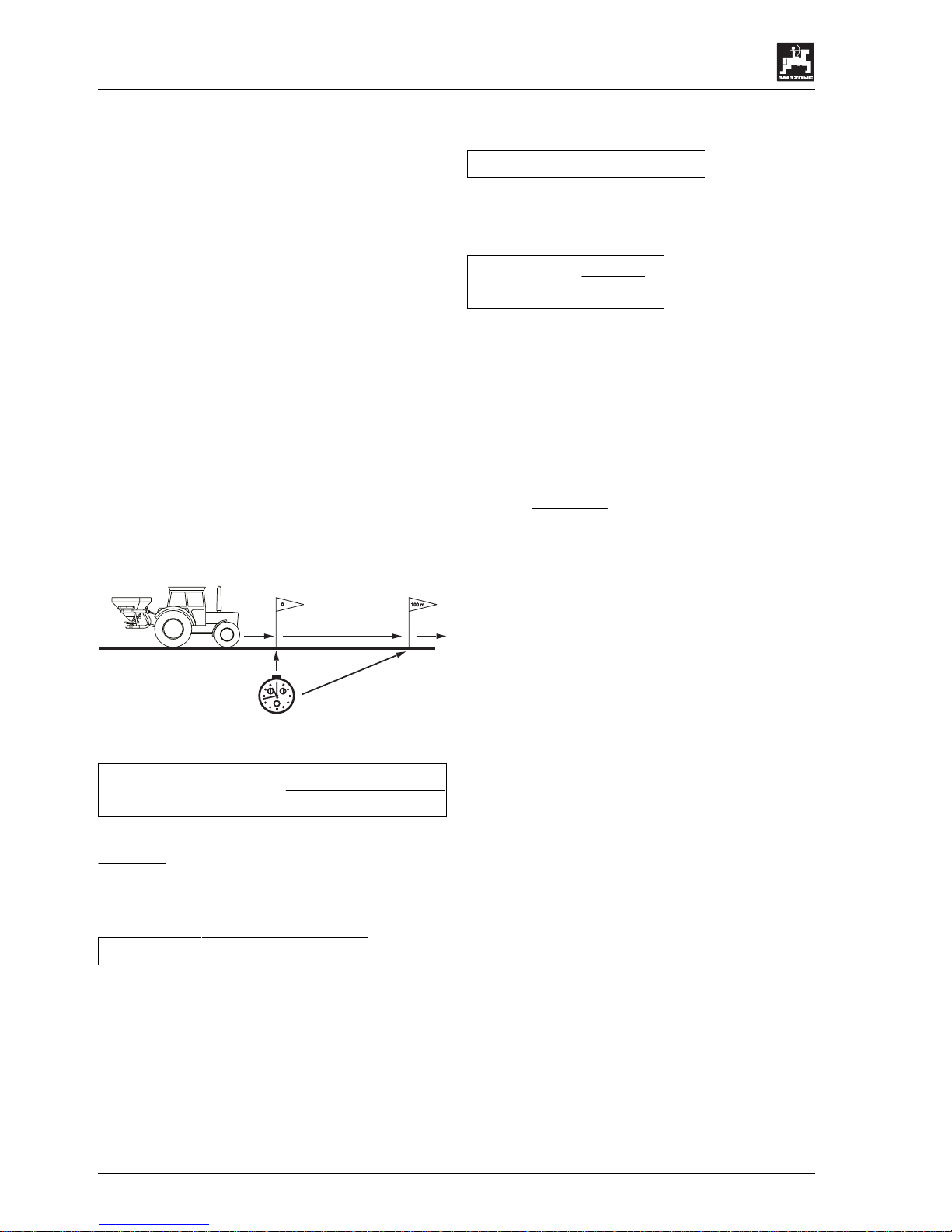
- Caref ull y meas ure a test dista nce of 100 m . Mark
beginning and end of the test distance.
- Drive test distance from beginning to end mark
with the intended, constant operational speed.
Determine the required time with the aid of a
stopwatch.
e.g. 100m in 120 sec.
-
Determine the operational speed [km/h].
Operational speed
[km/h]
=
360
time for 100m
Example: 100 m in 120 sec.
360
120 sec
= 3 km/h
2. Determining the required spread rate per
minute [g/min] for the desired spread rate:
So [g/min] = St [g/m²] x Fl [m²/min]
So: required spread rate
St: desired spread rate
Fl: area efficiency
Fl [m²/min] = W [m/min] x A [m]
Fl: Area efficiency
W: Travelled distance
A: Working width
W [m/min] =
F [m/h]
60
W: Travelled distance
F: Operational speed
Example:
Operational speed F: 3 km/h
Working width A: 4m
desired spread rate St: 50 g/m²
required spread rate So:? [g/min]
W
=
3000 [m/h]
60
= 50 m/min
F = 50 m/min x 4m = 200 m² /min
So = 50 g/m² x 200 m²/min
So = 10000 g/min
The necessary required spread is 10 kg/min.
Page 33

Putting into operation
33
DB 534 02. 02
3. Spread rate checking procedure
- Place a plastic wrap underneath the spreader.
- Lower the spreader to its lowest position.
- Move the working width reducer in its lowest
position.
- Start the towing vehicle’s engine. With the
manual gas lever c onstantly set the engine’s rev.
speed according to the PTO shaft rev. speed
(e.g. 540 min
-1
)
- Engage PTO shaft.
- Open the shutter for precisely 1 minute in the
desired shutter slide position.
- To determine the actually set spr ead rate [g/m²]
weigh the collected amount of spreadin g material
and compare with the determined required
spread rate [g/min].
F
If the actual and the desired spre ad rate
do not coincide, re-adjust the shutter
slide position. If necessary repeat the
spread rate check.
.
a
During the spread rate check be aware
of rotating implement parts and
spreading material particles being
thrown around. Danger of injury.
Page 34

34
Cleaning, maintenance and repair
DB 534 02. 02
8. Cleaning, maintenance and repair
a
As a matter of principle all repair-,
maintenance- and cleaning work as w ell
as remedy of function faults should be
carried out with disengaged universal
joint shaft and stopped vehicle engine.
Remove ignition key.
a
When doing maintenance work on the
lifted implement make sure that it is
secured by proper supports.
a
After disengaging the pto shaft the
mounted implement may still continue to
run by it’s dynamic masses. Begin to
work only when the implement has come
to a full standstill.
a
Any spare parts fitted must, as a
minimum meet with the implement
manufacturers' fixed technical
standards. Using original AMAZONE
spare parts for example ensures this.
a
All hydraulic hoses must be checked for
their operational safety in regular
intervals. Exchange in case of damage
or ageing. The period of use of any hose
circuit should not exceed six years. The
replacement hoses must correspond to
the technical demands of the implement
manufacturer.
a
When searching for leaks appropriate
aids should be used because of the
danger of injury.
a
Liquids leaking under high pressure
(hydraulic oil) can penetrate the skin and
cause severe injury. When injured see a
doctor immediately! Danger of infection.
a
Before starting to do repair work to the
hydraulic system, lower machine to the
ground, release the pressure and stop
vehicle engine.
a
Dispose of oil, grese and filters in the
appropriate manner.
a
Grease the shutter guides after any
operation.
a
In case of injuries caused by penet rating
oil consult a doctor immediately.
8.1 Cleaning
After use clean the machine with a normal jet of water
(greased implements only on washing bays with
oil traps).
Dismantle bottom group and clean carefully.
Treat dry machine with an anticorrosive agent(Only
use biologically degradable pr ot ecti ve agen ts ) .
Park machine with opened, greased shutter.
Page 35
Cleaning, maintenance and repair
35
DB 534 02. 02
8.1.1 Dismantling of bottom group
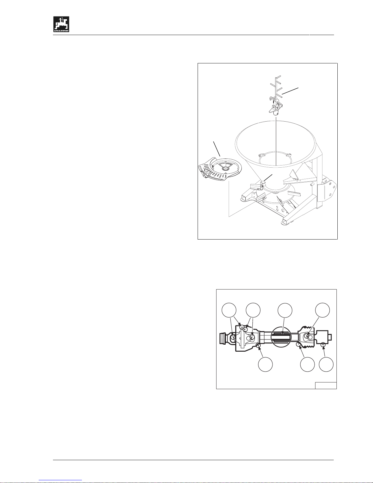
- Twist the agitator (1) in counter clockwise
direction and remove.
- Lift the bottom group lock ing ratchet (2) and pull
out the bottom group (3) to the rear.
The re-assembly is done in vice ve rsa order.
8.2 Lubrication
8.2.1 Greasing of PTO shaft
The adjacent illustrati on shows th e greasing in tervals
for the PTO shaft in hours. For further information,
please refer to the instruction manual of the PTO
shaft manufacturer..
ZA 155
40h
8h40h
8h8h 8h
20h
1
2
3
Page 36
36
Cleaning, maintenance and repair
DB 534 02. 02
8.2.2 Gearbox oil
The gearbox is supplied with sufficient oil by the
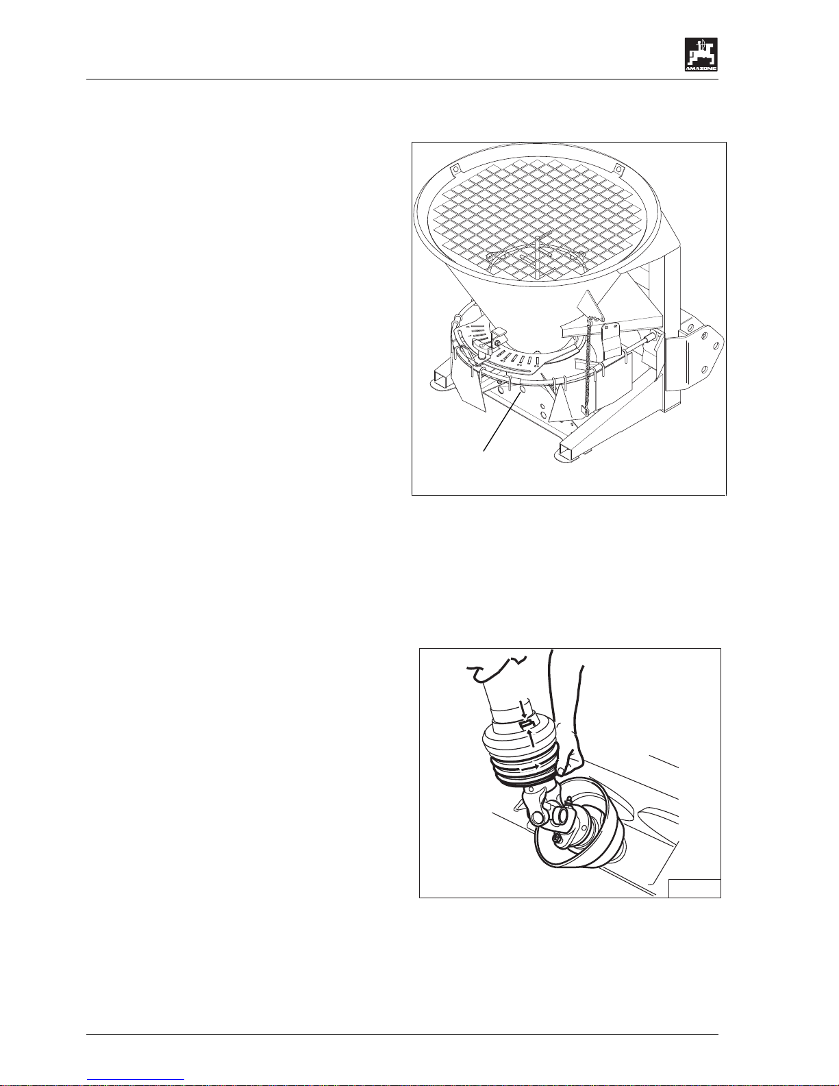
manufacturer. With horizontally mounted
implement and after having removed the oil drain
plug (1) the oil level should be visible on the
lower edge of the hole. A refilling of o il normally is
not necessary.
External symptoms, e. g. fresh oil spots on the
parking place or on machine par ts and/or loud noise
development, however, indicate an oil leakage of the
gear box housing. Search for reason, care for remedy
and refill oil.
For refilling oil
- lift the spreader horizontally,
- remove oil drain plug (1),
- refil oil (until lower edge of the hole),
- Screw in oil drain plug (1).
Oil filling quantity: 0,35 l SAE 90
Maintenance intervals
• 1. oil change after 50 hours of operation.
then oil change every 500 to 800 hours of oper at ion –
at least, however, once a year.
8.3 Shear-off safety on the PTO shaft
The separately suppli ed bolts 8 x 30, DIN 931, 8.8
are spare shear bolts (1) for fixing the PT O shaft
yoke on the flange of the gearbox input shaft.
Always apply grease when fitting the PTO shaft to the
gearbox input shaft.
ZA 151
1
Page 37
Cleaning, maintenance and repair
37
DB 534 02. 02
8.4 Exchange of spreading vanes
I
Exchange spreading vanes as soon as
breakage by wear can be noted.
I
Take care when fitting the spreading
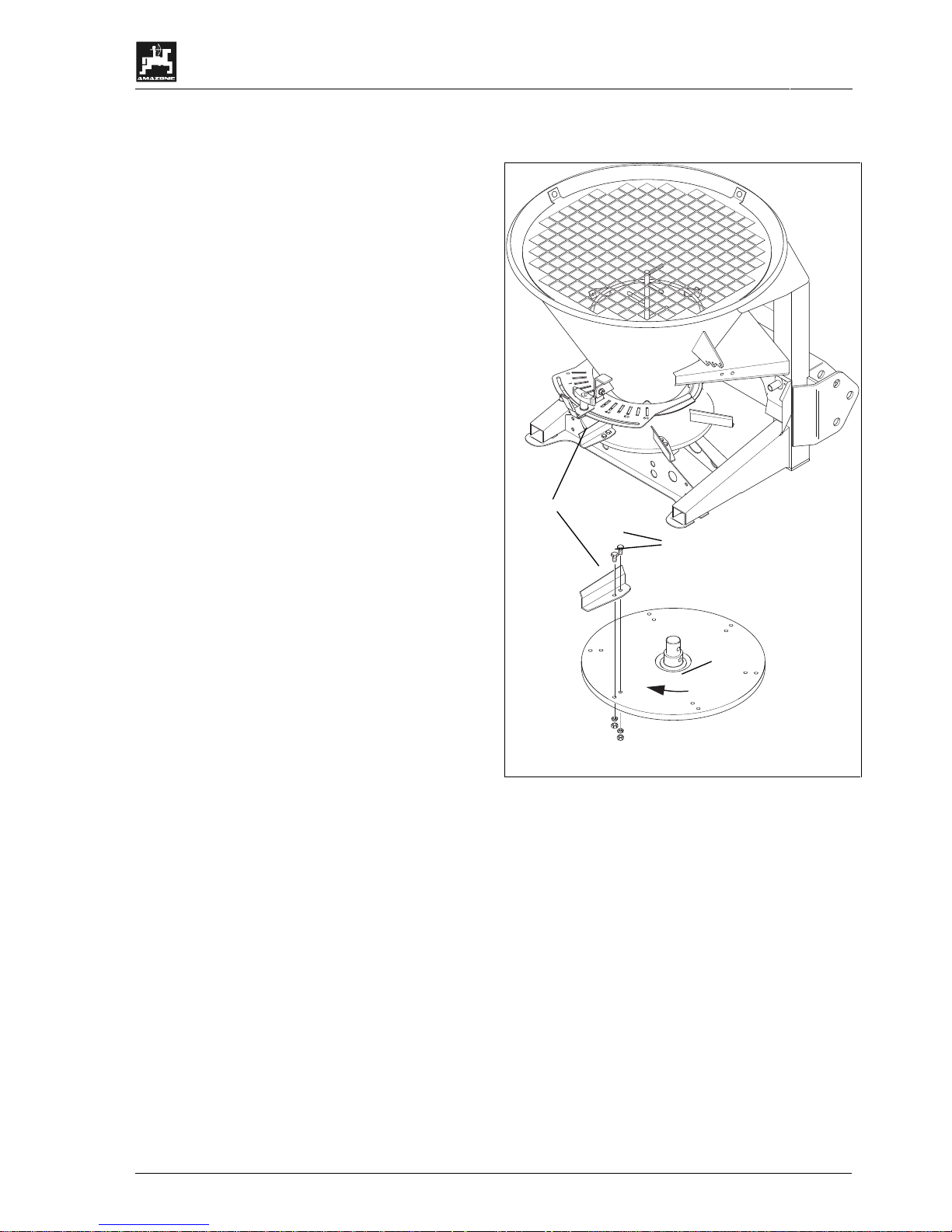
vanes. The open side of the L-shaped
spreading vanes (1) shows in rotating
direction (2).
Exchange spreading vane as follows:
- Remove spreading width reducer.
- Remove bolts (3) and ex change spreading vane
(1).
- Retighten bolts (3) firmly.
2
3
1
Page 38

38
Setting charts
DB 534 02. 02
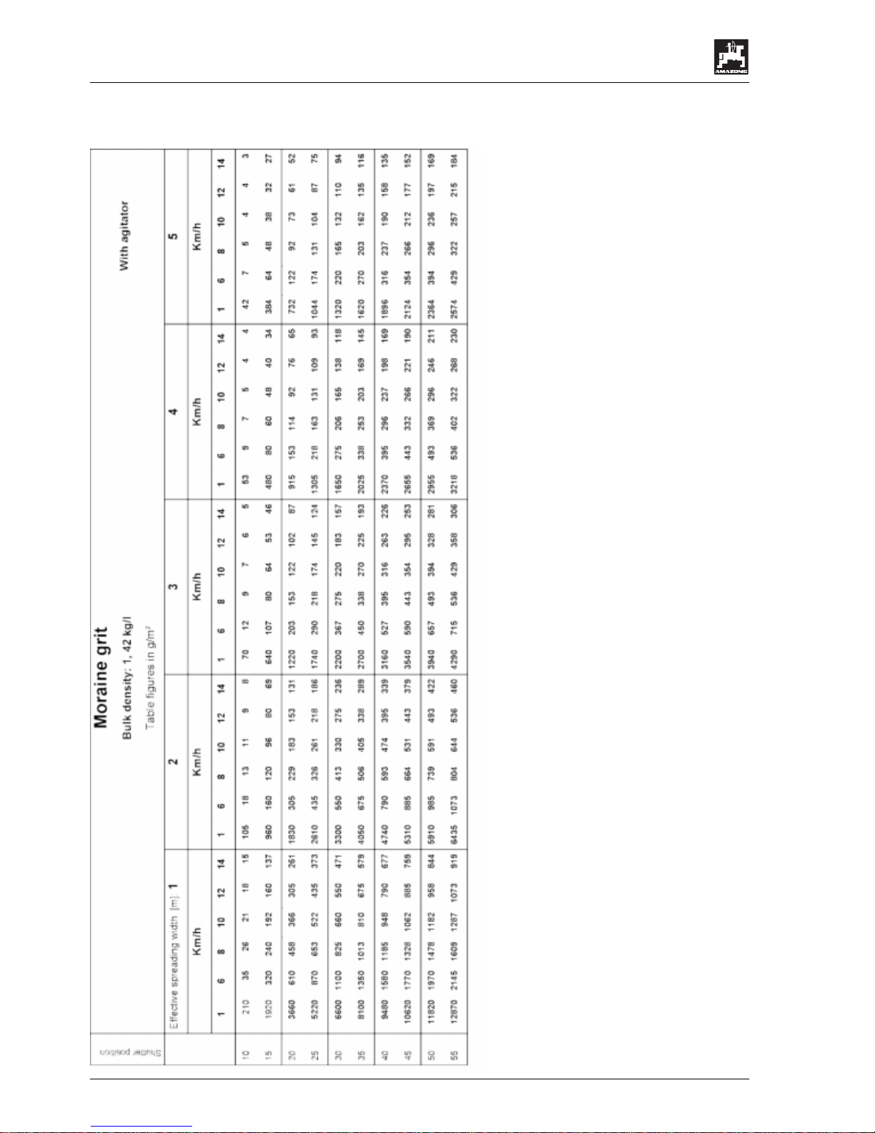
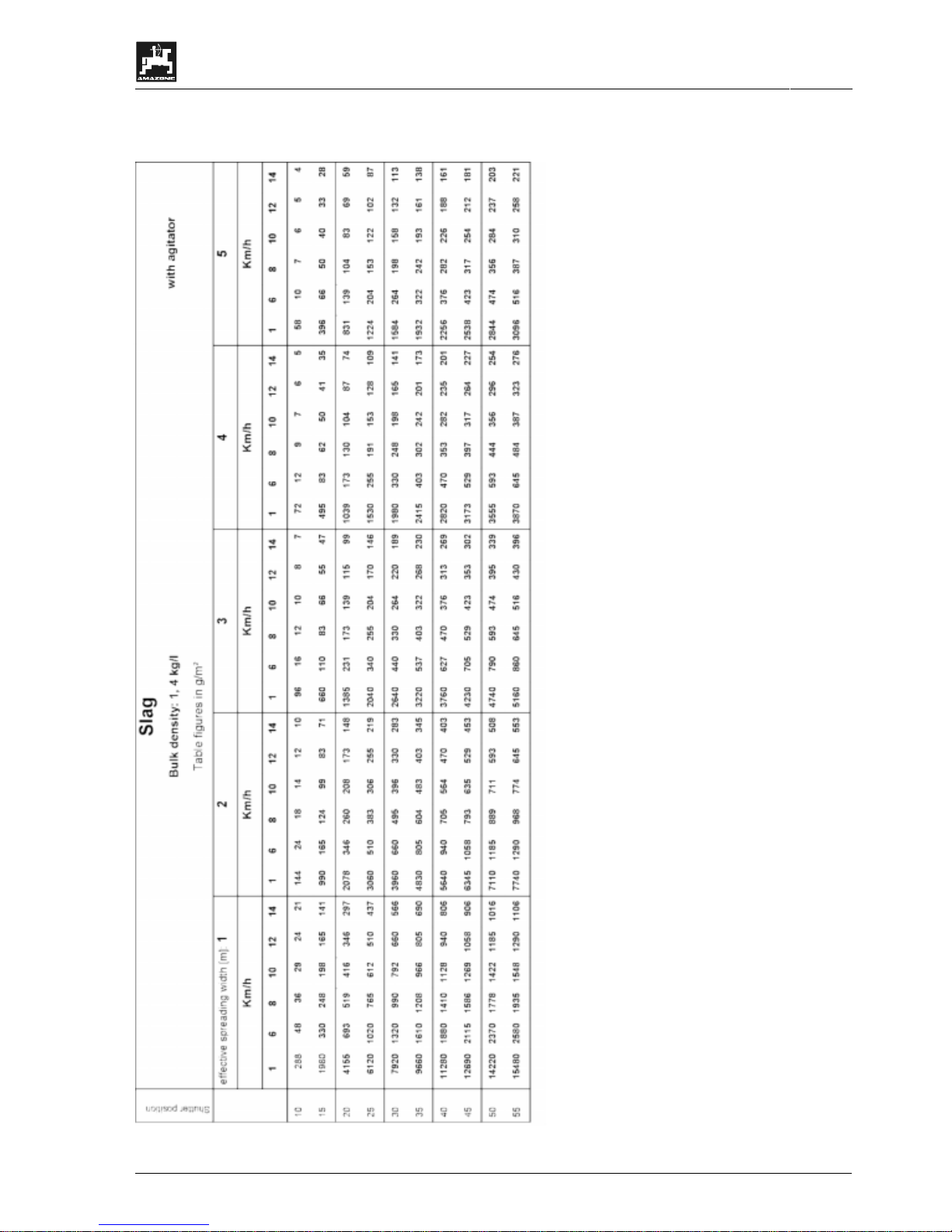
9. Setting charts
9.1 Sand
PTO shaft rev. speed: 540 R.P.M.
Distance between spreading disc and ground: 60 cm
Setting chart values are indicated in g/m².
Page 39

Setting charts
39
DB 534 02. 02
9.2 Thawing salt
Page 40
40
Setting charts
DB 534 02. 02
9.3 Moraine grit
Page 41
Setting charts
41
DB 534 02. 02
9.4 Slag
Page 42

42
DB 534 02. 02
Page 43

43
DB 534 02. 02
Page 44

H. DREYER GmbH & Co. KG
P. O. Box 51
D-49202 Hasbergen-Gaste
Germany
Tel.: ++49 (0) 54 05 50 1-0
Telefax: ++49 (0) 54 05 50 11 93
e-mail: [email protected]
http:// www.amazone.de
Branch factories at: D-27794 Hude • D-04249 Leip zi g • F-57602 Forbach
Subsidiaries in England and Franc e
Factories for mineral fertiliser broadcasters, -storage halls, - handling systems. Seed drills,
Soil cultivation machinery. Field boom sprayers. Municipal machinery.
 Loading...