

Page 1
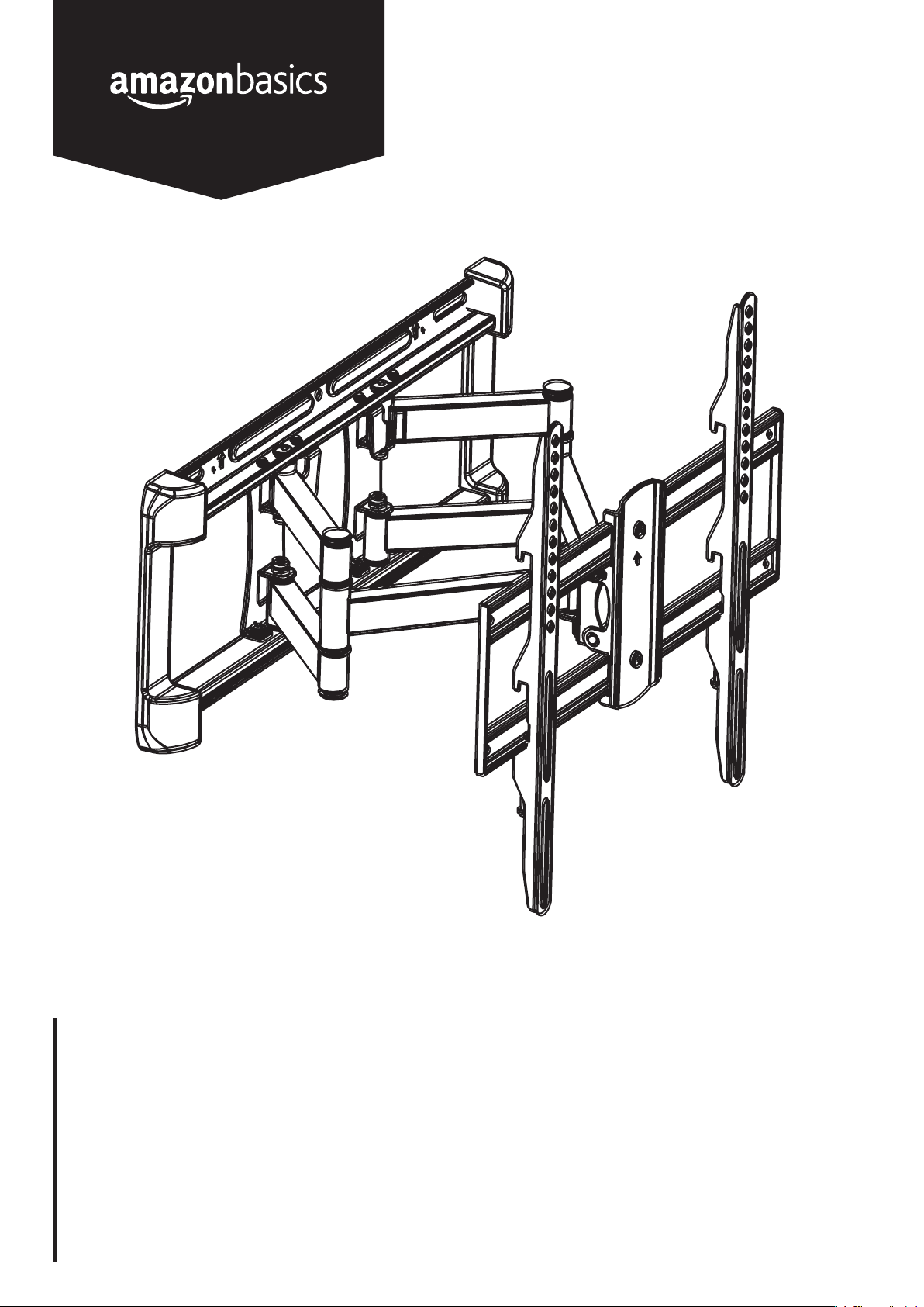
Dual Arm Full Motion TV Mount, 32” to 65”
Support Mouvement Complet à Deux Bras pour Téléviseur, 81 à 165 cm (32 à 65 po)
Voll Bewegliche TV-Aufhängung mit Doppelarm, 81 bis 165 cm (32 bis 65 Zoll)
Supporto TV Full Motion a Doppio Braccio, da 81 a 165 cm (da 32 a 65 Pollici)
Soporte de TV con Movimiento Completo y Doble Brazo, 81 a 165 cm (de 32 a 65 Pulgadas)
TV-beugel met dubbele arm en volledig beweegbaar, 81,3cm tot 165,1cm
デュアルアームフルモーション TV マウント,81 ~165 cm (32 インチ から 65 インチ)
B07MR4GRQP
Page 2
English ������������������������������������������������������������������������������������������������������������������������������� 3
Français ����������������������������������������������������������������������������������������������������������������������������� 6
Deutsch ������������������������������������������������������������������������������������������������������������������������������ 8
Italiano ����������������������������������������������������������������������������������������������������������������������������� 10
Español ���������������������������������������������������������������������������������������������������������������������������� 12
Nederlands ����������������������������������������������������������������������������������������������������������������������� 14
日本語 ������������������������������������������������������������������������������������������������������������������������������� 16
Contents • Contenu • Inhalt • Contenuto • Contenido • Inhoud • 内容 ����������������������������18
Assembly • Montage • Montage • Montaggio • Montaje • Montage • 組み立て ����������������19
Page 3
Welcome Guide • English
IMPORTANT SAFEGUARDS
Read these instructions carefully and retain them for future use. If this product is passed to a third party, then these
instructions must be included.
When using the product, basic safety precautions should always be followed to reduce the risk of injury including the following:
CAUTION
CAUTION
• Read these instructions before you begin. If you are unsure about any part of the process, contact a professional contractor
or installer for assistance. Only use the correct tools as noted in these instructions. Improper installation can result in personal
injuries and/or damage.
• At least two people with technical knowledge are required for installing the mount and TV. Keep children and pets away during
installation, as they might swallow small parts or packaging resulting in danger of choking/suffocation.
• Check carefully to ensure that there are no missing or damaged parts. Never use defective parts.
• Use and install this product only according to the intended use as described within these instructions. Misuse may lead to
hazards resulting in potential damage and personal injuries. Do not modify the structure of this product in any way. Manufacturer
cannot be liable for direct or indirect damage or personal injuries caused by incorrect mounting, incorrect use, modification to
the structure, or incorrect assembly. Keep the instruction manual in a safe place.
• Refer to the instruction manual provided with the TV you are going to install on this product. It includes additional information for
the mounting, ventilation and suitable mounting location. Compare the technical data and requirements to make sure that this
product is suitable for your TV.
• IMPORTANT! Choose the right place to install the wall plate.
• For safety reasons make sure the wall can support at least 4 times the weight of the TV and mount. The manufacturer takes no
responsibility for failure caused by walls of insufficient strength.
• The maximum wall covering thickness; such as gypsum drywall, lath, plastic, etc. should not be greater than 0.63” / 16 mm
(wood stud walls) or 0.4” / 10 mm (masonry walls).
• Do not mount to drywall alone.
• Examine the wall you want to install the mount to before you start installation. Make sure that there are no hidden power supply
cables, gas pipes, water pipes or other objects hidden in the wall that might be hit by the drill, screws or other hardware.
• For wood stud walls: This mount is designed to be mounted to 2” x 4” (51 mm x 102 mm) and Grade No. 2, wood studs that
are spaced 16” (406 mm) on center. Wood studs should be
2” x 4” (51 mm x 102 mm), at minimum: 1.5” x 3.5” (38 mm x 89 mm).
• For concrete walls: The bracket must be installed into a solid concrete wall. Make sure the concrete wall is suited for Standard
Test Method for Compression Strength of Cylindrical Concrete Specimens, ASTM C39, or equivalent.
• This product should never be mounted to metal framing studs or bricks.
• If the mounting bracket will be attached to any structure other than specified in this manual, only a licensed professional
contractor/installer should perform this installation. The supporting structure must support, at minimum, four times the combined
weight of the mounting bracket and TV. It is the responsibility and liability of the installer to ensure the suitability of the supporting
structure.
• Never install into furniture! This can lead to instability resulting in personal injuries and/or damage.
• Always support the TV with your hands when making adjustments. Make sure to tighten screws and other connections well, but
do not over-tighten them. Never use an electric tool to tighten screws and nuts.
• Once you have mounted the bracket and TV, ensure they are sufficiently secure and safe to use.
This product is for indoor use only! Never use the mount outdoors!
This product is for private household use only and therefore may not be used in public places like restaurants or
hotels.
Before First Use
• Check for transport damages.
DANGER
Risk of suffocation! Keep any packaging materials away from children – these materials are a potential source
of danger, e.g. suffocation.
Cleaning and Maintenance
• Periodically clean your mount with a dry cloth. Inspect all screws and hardware at regular intervals to ensure that no connections
have become loose over time. Re-tighten as needed.
• Users should check and maintain the product frequently to ensure the TV and mount work normally, safely and securely. Make
sure the screws are tightened every two months.
3
Page 4
FCC – Supplier’s Declaration of Conformity
Unique Identifier B07MR4GRQP Dual Arm Full Motion TV Mount, 32” to 65”
Responsible Party - U.S.
Contact Information
Address 410 Terry Ave N.
Telephone Number (206) 266-1000
Amazon.com Services, Inc
Seattle, WA
98109, United States
FCC Compliance Statement
1. This device complies with Part 15 of the FCC rules. Operation is subject to the following two conditions:
(1) this device may not cause harmful interference, and
(2) this device must accept any interference received, including interference that may cause undesired operation.
2. Changes or modifications not expressly approved by the party responsible for compliance could void the user’s authority to
operate the equipment.
FCC Interference Statement
This equipment has been tested and found to comply with the limits for a Class B digital device, pursuant to part 15 of the
FCC Rules. These limits are designed to provide reasonable protection against harmful interference in a residential installation.
This equipment generates, uses and can radiate radio frequency energy and, if not installed and used in accordance with the
instructions, may cause harmful interference to radio communications. However, there is no guarantee that interference will not
occur in a particular installation. If this equipment does cause harmful interference to radio or television reception, which can be
determined by turning the equipment off and on, the user is encouraged to try to correct the interference by one or more of the
following measures:
• Reorient or relocate the receiving antenna.
• Increase the separation between the equipment and receiver.
• Connect the equipment into an outlet on a circuit different from that to which the receiver is connected.
• Consult the dealer or an experienced radio/TV technician for help.
Canada IC Notice
• This Class B digital apparatus complies with Canadian CAN ICES-3(B) / NMB-3(B) standard.
Disposal
The Waste Electrical and Electronic Equipment (WEEE) Directive aims to minimize the impact of electrical and electronic
goods on the environment, by increasing re-use and recycling and by reducing the amount of WEEE going to landfill. The
symbol on this product or its packaging signifies that this product must be disposed separately from ordinary household
wastes at its end of life. Be aware that this is your responsibility to dispose of electronic equipment at recycling centers in
order to conserve natural resources. Each country should have its collection centers for electrical and electronic equipment
recycling. For information about your recycling drop off area, please contact your related electrical and electronic equipment
waste management authority, your local city office, or your house hold waste disposal service.
4
Page 5
Specifications
Display size: 32” - 65” (81 - 165 cm)
Max. load: 100 lbs (45 kg)
200 x 100 mm
200 x 200 mm
300 x 200 mm
Mounting pattern:
Tilt range: -6° to 10° up/down
Pan/swivel range: up to 180°
Profile: 2.6 - 16.0” (6.7 - 40.7 cm)
Level correction: -6° to 6° left/right
300 x 300 mm
400 x 200 mm
400 x 300 mm
400 x 400 mm
Warranty Information
To obtain a copy of the warranty for this product:
US: amazon.com/AmazonBasics/Warranty
UK: amazon.co.uk/basics-warranty
US: +1-866-216-1072
UK: +44 (0) 800-279-7234
Feedback and Help
Love it? Hate it? Let us know with a customer review. AmazonBasics is committed to delivering customer-driven products that live
up to your high standards. We encourage you to write a review sharing your experiences with the product.
US: amazon.com/review/review-your-purchases#
UK: amazon.co.uk/review/review-your-purchases#
US: amazon.com/gp/help/customer/contact-us
UK: amazon.co.uk/gp/help/customer/contact-us
5
Page 6
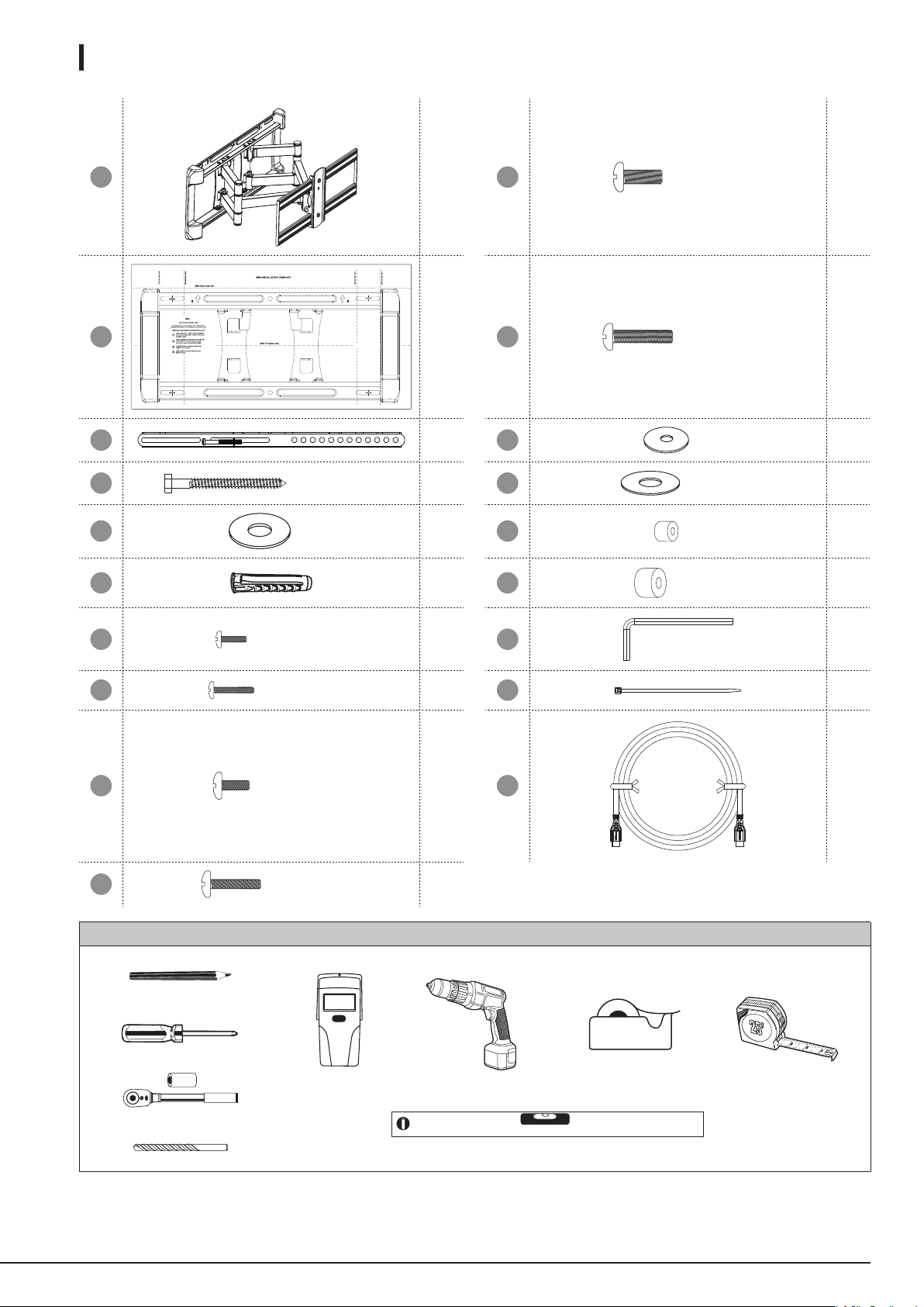
Contents • Contenu • Inhalt • Contenuto • Contenido • Inhoud • 内容:
MB x1
IT x1
MA x2
A
B
C
M6.3 x 63 mm
M6
x4
x4
x4
H
J
K
L
M
M8 x 20 mm
I
M8 x 30 mm
M4
M6 / M8
M4
M6 / M8
x4
x4
x4
x4
x4
x4
D
E
F
G
You will need / Vous aurez besoin de / Sie benötigen / Sono necessari / Necesitará / U hebt het volgende nodig / 必 要 な 物:
M4 x 12 mm
M4 x 22 mm
M6 x 14 mm
M6 x 24 mm
x4
x4
x4
x4
N
O
P
x1
x6
x1
18
Page 7
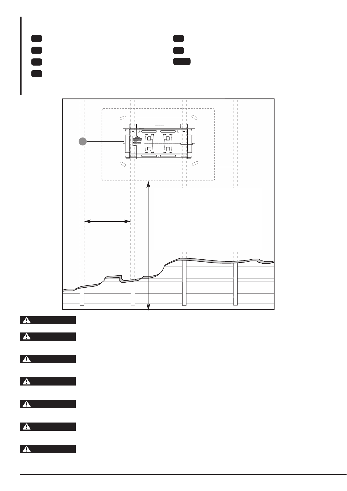
Assembly • Montage • Montage • Montaggio • Montaje • Montage • 組み立て
EN
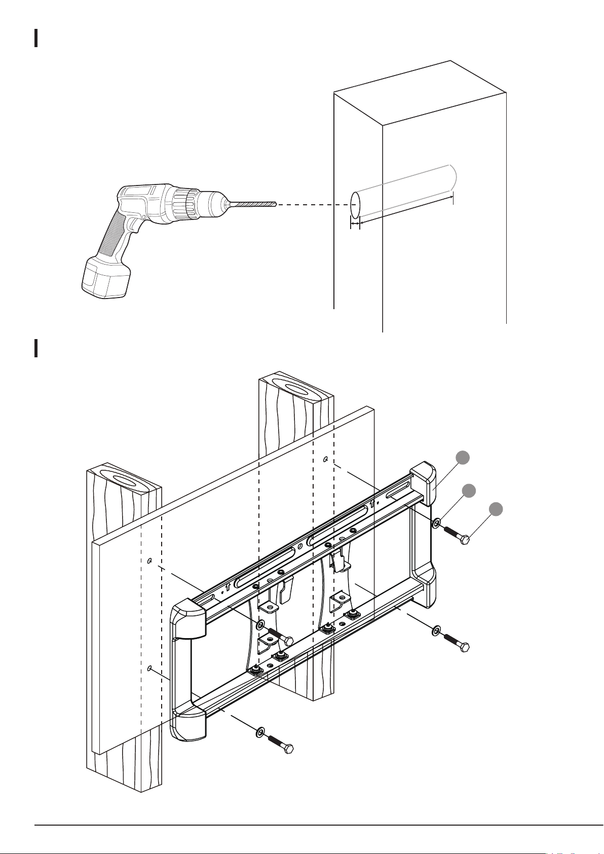
Mounting to the wall (Drywall)
FR
Montage sur le Mur (Placoplâtre)
DE
Montage an der Wand (Gipskarton)
IT
Montaggio a Parete (Cartongesso)
1:
IT
16” (406 mm)
ES
Montaje en la Pared (Panel de Yeso)
NL
Op de muur monteren (gipsplaat)
日本語
壁(乾式壁)に取り付ける
TV
Height to bottom of TV
Hauteur par rapport à la partie inférieure du téléviseur
Höhe bis zur Unterkante des Fernsehers
Altezza alla parte bassa del TV
Altura desde la parte inferior del TV
Hoogte tot de onderkant van de tv
テレビの一番下までの高さ
CAUTION
ATTENTION
VORSICHT
ATTENZIONE
ATENCIÓN
VOORZICHTIG
注意
For safety reasons, this mount must be secured to at least two wood studs no less than 16” (406 mm)
apart. The studs must be capable of supporting the combined weight of the mount and display.
Pour des raisons de sécurité, ce support doit être fixé solidement sur au moins deux montants en bois
d’un espacement minimum de 406 mm. Les solives doivent être capables de supporter le poids combiné
du support et de l’écran.
Aus Sicherheitsgründen muss diese Halterung an mindestens zwei Holzständern mit einem Abstand von
mindestens 406 mm befestigt werden. Die Balken müssen das gemeinsame Gewicht der Halterung und
des Monitors tragen können.
Per motivi di sicurezza, questo supporto deve essere fissato ad almeno due montanti di legno ad una
distanza minima di 406 mm l’uno dall’altro. I montanti devono essere in grado di sostenere il peso
combinato del supporto e del display.
Por motivos de seguridad, este soporte debe asegurarse a dos montantes de madera con una separación
no inferior a 406 mm. Los montantes deben poder soportar el peso combinado del soporte y de la
pantalla.
Deze beugel moet om veiligheidsredenen worden bevestigd op minstens twee houten dragers met een
maximale tussenruimte van 406mm. De dragers moeten het totale gewicht van de beugel en het scherm
kunnen dragen.
安全上の理由から、このマウントは 406 mm を超える間隔を持つ、最低2本 の間柱にしっかり取り
付ける必要があります。間柱はマウントとディスプレーを合わせた重さを支えることができる必要があ
ります。
19
Page 8
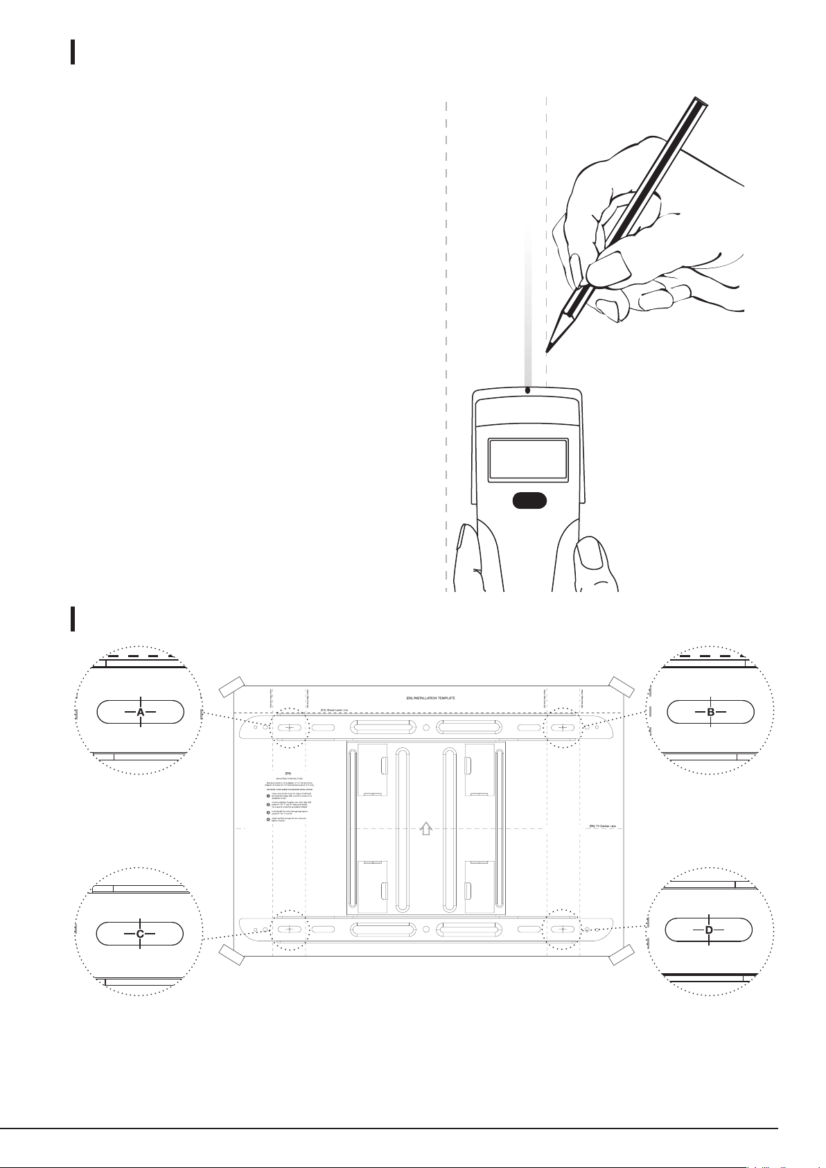
2:
• Use a high-quality stud finder to locate two adjacent studs.
Mark both edges of each stud to help identify the exact
center.
• Utilisez un détecteur de montants de qualité supérieure
pour détecter deux montants adjacents à l’endroit où
vous souhaitez installer votre support. Marquez les deux
extrémités de chaque montant afin de vous permettre de
déterminer le centre avec précision.
• Verwenden Sie einen hochwertigen Balkensucher, um 2
nebeneinanderliegende Ständer zu finden, an denen Sie Ihre
Halterung montieren möchten. Markieren Sie beide Kanten
der beiden Ständer, um jeweils die exakte Mitte zu ermitteln.
• Utilizzare un rilevatore di montanti di alta qualità per
individuare due montanti adiacenti su cui si desidera
installare il supporto. Contrassegnare entrambi i bordi di
ciascun montante per identificare meglio l’esatto centro.
• Utilice un detector de vigas de alta calidad para localizar
dos montantes adyacentes en los que desee instalar el
soporte. Marque ambos extremos de cada montante para
identificar el centro exacto.
• Gebruik een hoogwaardige balkzoeker om de twee
aangrenzende dragers te zoeken waarop u de beugel wilt
bevestigen. Markeer beide randen van elke drager om het
exacte midden te bepalen.
• 安全上の理由から、このマウントは 406 mm を超える間
隔を持つ、最低2本の間柱にしっかり取り付ける必要が
あ り ま す 。間 柱 は マ ウ ン ト と デ ィ ス プ レ ー を 合 わ せ た 重 さ
を 支 えることが できる 必 要 が ありま す。
3:
20
Page 9
4:
A / B / C / D
5:
5/32"
(4 mm)
2.5" (64 mm)
MB
B
A
21
Page 10
Assembly • Montage • Montage • Montaggio • Montaje • Montage • 組み立て
EN
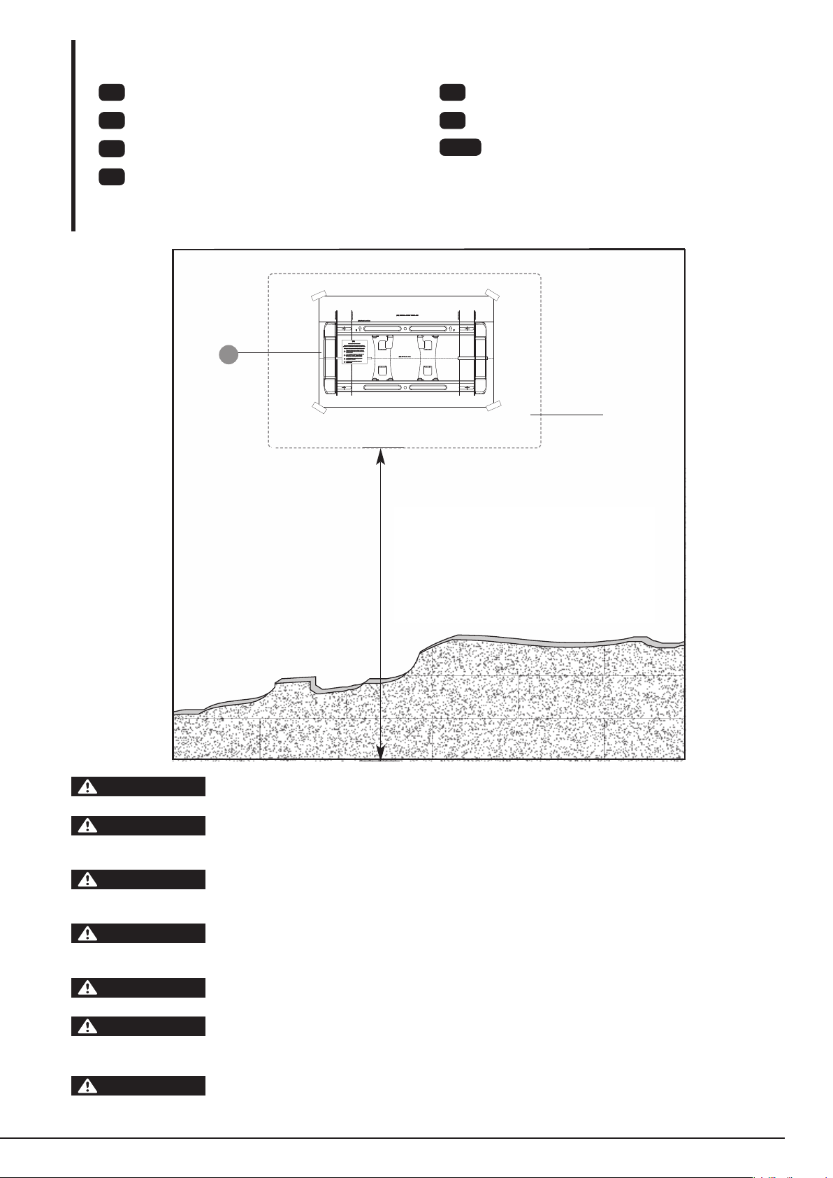
Mounting on Concrete Wall
FR
Montage Sur le Mur (Béton)
DE
Montage an der Wand (Beton)
IT
Montaggio a Parete (Calcestruzzo)
1:
IT
ES
Montaje en la Pared (Hormigón)
NL
Op een gemetselde muur monteren
日本語
壁(コンクリート)に取り付けるす。
TV
Height to bottom of TV
Hauteur par rapport à la partie inférieure du téléviseur
Höhe bis zur Unterkante des Fernsehers
Altezza alla parte bassa del TV
Altura desde la parte inferior del TV
Hoogte tot de onderkant van de tv
テレビの一番下までの高さ
22
CAUTION
ATTENTION
VORSICHT
ATTENZIONE
ATENCIÓN
VOORZICHTIG
注意
For safety reasons, the concrete wall must be capable of supporting the combined weight of the mount
and the display. The manufacturer takes no responsibility for failure caused by walls of insufficient strength.
Pour des raison de sécurité, le mur en béton doit être capable de supporter le poids combiné du support
et de l’écran. Le fabricant décline toute responsabilité en cas de défaillance due à des murs de résistance
insuffisante.
Aus Sicherheitsgründen muss die Betonwand das gemeinsame Gewicht der Halterung und des Monitors
tragen können. Der Hersteller übernimmt keine Haftung für Fehlfunktionen aufgrund unzureichender
Wandstärke.
Per motivi di sicurezza, la parete in calcestruzzo deve essere in grado di sostenere il peso combinato del
supporto e del display. Il produttore non si assume alcuna responsabilità per guasti causati da pareti non
sufficientemente resistenti.
Por motivos de seguridad, la pared de hormigón debe soportar el peso combinado del soporte y de la
pantalla. El fabricante no se responsabiliza de daños provocados por paredes poco resistentes.
De betonnen wand moet om veiligheidsredenen het totale gewicht van de beugel en het scherm kunnen
dragen. De fabrikant is niet aansprakelijk voor schade die is veroorzaakt door wanden met onvoldoende
sterkte.
安全上の理由から、コンクリート壁はマウントとディスプレーを合わせた重 さを支えることができる必
要があります。メーカーは壁の強度不足のため生 じた失敗についての責任は負いかねます。
Page 11
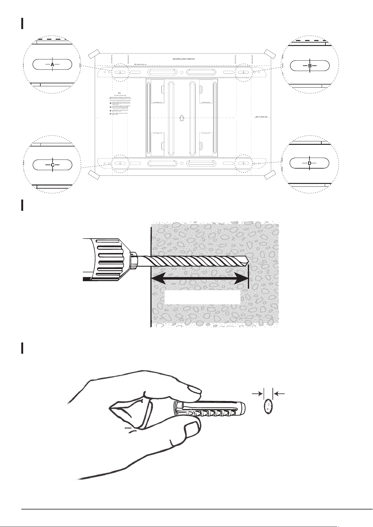
2:
3:
4:
3” (76 mm)
5/16” (8 mm)
23
Page 12
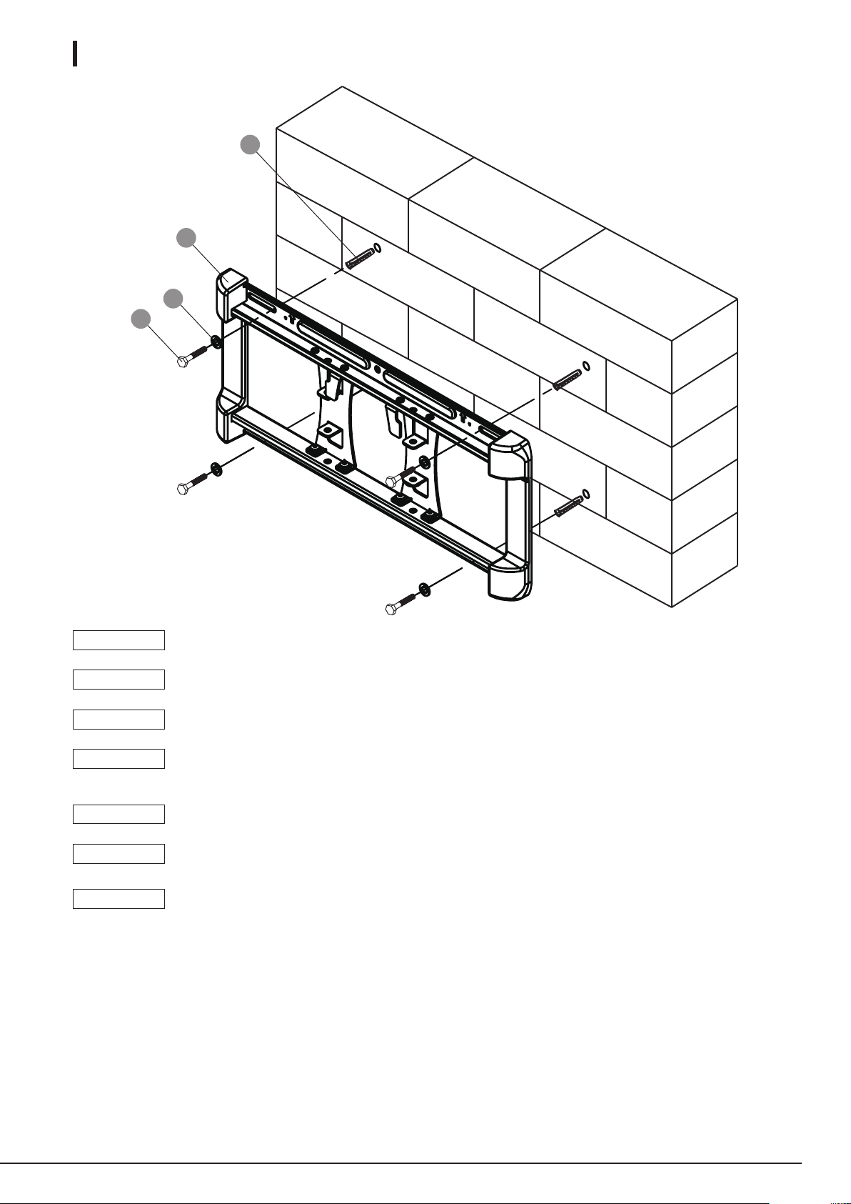
5:
C
MB
B
A
NOTICE
REMARQUE
HINWEIS
AVVISO
AVISO
OPMERKING
注意
If the concrete wall is covered by a layer of plaster or drywall, the concrete anchor must pass completely through
the layer to rest flush with the concrete surface.
Si le mur en béton est recouvert d’une couche de plâtre ou de cloison sèche, l’ancrage à béton doit traverser
complètement la couche pour rester au ras de la surface du béton.
Wenn die Betonwand mit einer Schicht Putz oder Gipskarton bedeckt ist, muss der Betondübel vollständig durch
diese Schicht reichen, um bündig mit der Betonoberfläche abzuschließen.
Se la parete in calcestruzzo è ricoperta da uno strato di intonaco o cartongesso, l’ancoraggio in
calcestruzzo deve passare completamente attraverso lo strato per rimanere a filo con la superficie in
calcestruzzo.
Si el muro de hormigón está cubierto por una capa de yeso o paneles de yeso, el anclaje de hormigón
debe sobrepasar completamente la capa para que quede al ras de la superficie del hormigón.
Als de betonnen wand bedekt is met een gipslaag of gipsplaat, moet het betonnen anker volledig door de laag
worden gestoken, zodat deze gelijk ligt met het betonoppervlak.
コンクリートの 壁 が 何 層 か の しっくいまたはプラスタ ー ボ ードで 覆 わ れ て い る 場 合は 、コンクリートアンカ ー は
それらの層を完全につきぬけ、コンクリ ートの壁と同じ高さであることが必要です。
24
Page 13
Assembly • Montage • Montage • Montaggio • Montaje • Montage • 組み立て
EN
Attaching the Mount Arms to Display
FR
Fixation Des Bras du Support Sur L’écran
DE
Montagearme am Monitor befestigen
IT
Fissaggio Dei Bracci di Montaggio al Display
ES
Colocación de Los Brazos Del Soporte a la Pantalla
NL
Op een gemetselde muur monteren
日本語
マ ウ ン ト ア ー ム を デ ィ ス プ レ ー ( テ レ ビ
に接 続する
1:
L M
MA
NOTICE
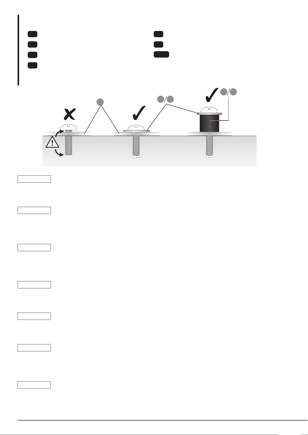
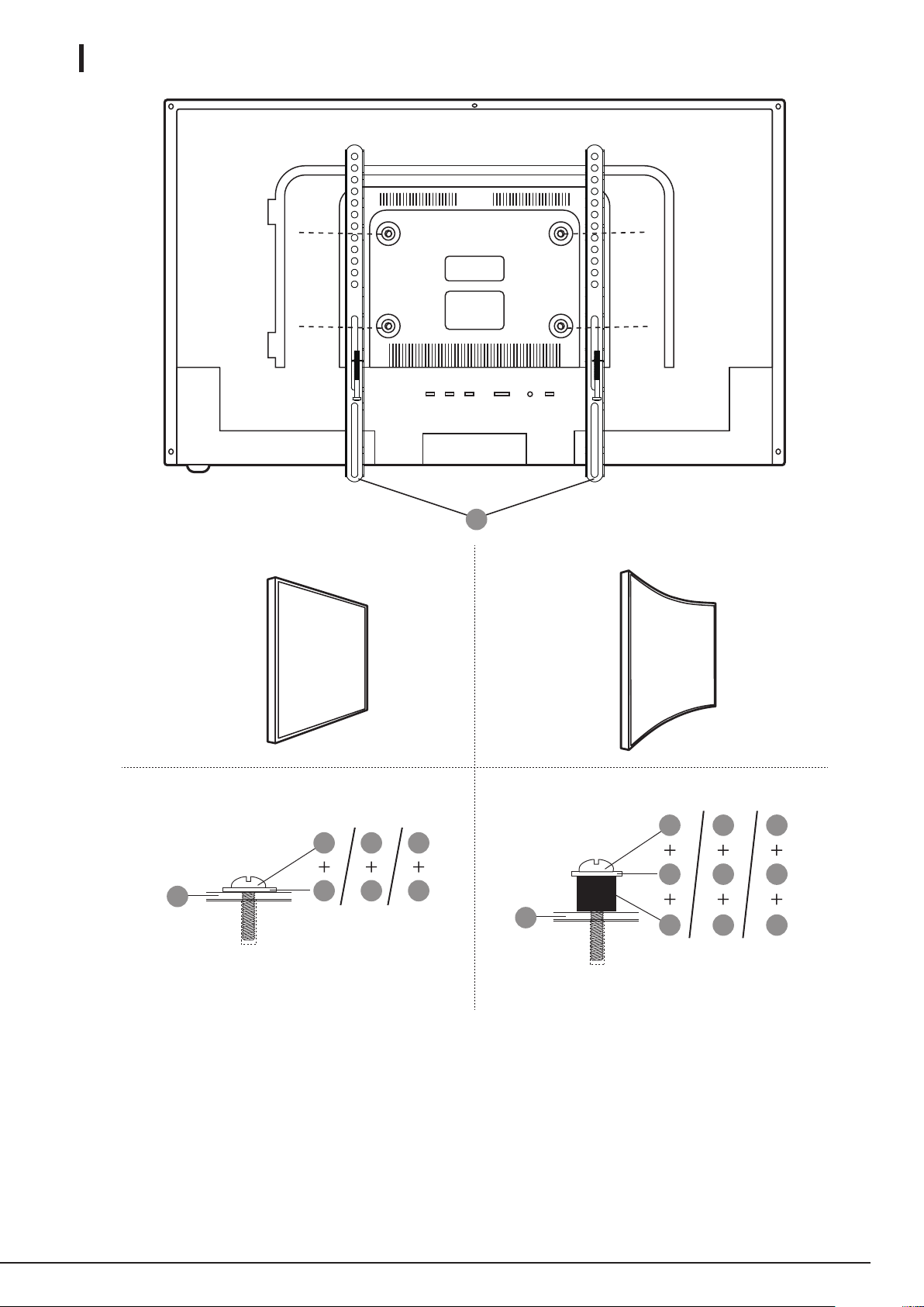
• Determine the correct length of screw to use by examining the back of your display.
• Determine the correct diameter of screw to use by carefully trying one of each size (M4, M6 and M8) from the hardware kit. Do
not force any of the screws – if you feel resistance stop immediately and try a smaller diameter screw.
J K
REMARQUE
• Déterminez la longueur de vis appropriée à utiliser en examinant le dos de votre écran.
• Déterminez le diamètre de vis approprié à utiliser en essayant avec précaution une de chaque taille (M4, M6 et M8) contenue
dans le kit de matériel. Ne pas forcer les vis : si vous sentez de la résistance, arrêtez-vous immédiatement et essayez une vis de
diamètre inférieur.
HINWEIS
• Ermitteln Sie die korrekte Länge der zu verwendenden Schrauben, indem Sie die Rückseite Ihres Monitors überprüfen.
• Ermitteln Sie den korrekten Durchmesser der zu verwendenden Schrauben, indem Sie vorsichtig jede der Größen (M4, M6
und M8) aus dem Befestigungsteile-Set ausprobieren. Wenden Sie keine Gewalt an den Schrauben an – wenn Sie Widerstand
fühlen, stoppen Sie sofort und probieren Sie eine Schraube mit einem kleineren Durchmesser aus.
AVVISO
• Determinare la lunghezza corretta della vite da utilizzare esaminando il retro del display.
• Determinare il corretto diametro della vite da utilizzare provando attentamente una delle dimensioni (M4, M6 e M8) dal kit del
materiale metallico. Non forzare nessuna delle viti; se si sente resistenza, fermarsi subito e provare una vite di diametro inferiore.
AVISO
• Determine la longitud correcta del tornillo que debe utilizar examinando la parte trasera de la pantalla.
• Determine el diámetro correcto del tornillo que debe utilizar probando uno de cada tamaño (M4, M6 y M8) del kit de tornillería.
No fuerce ninguno de los tornillos; si nota resistencia, pare inmediatamente y pruébelo un tornillo de diámetro inferior.
OPMERKING
• Bepaal de juiste lengte van de te gebruiken schroef door de achterkant van uw scherm te onderzoeken.
• Bepaal de juiste diameter van de te gebruiken schroef door voorzichtig alle groottes (M4, M6 en M8) uit de materiaalkit te
gebruiken. Forceer de schroeven niet. Als u weerstand voelt, stopt u onmiddellijk en probeert u een schroef met een kleinere
diameter te gebruiken.
注意
• ディスプレーの裏を調べ、ネジの正しい長さを決めます。
• ディスプレーの裏が平らでマウント用の穴が面と同じ高さであれば、ハードウェアキットに 含まれている短いネジ (D、F ま
たは H)を使います。
25
Page 14
2:
MA
MA
A B
D
J
F
K
H
K
MA
E
J
L
G
K
M
I
K
M
26
Page 15
Assembly • Montage • Montage • Montaggio • Montaje • Montage • 組み立て
EN
Installation
FR
Montage Final
DE
Abschließende Montage
IT
Montaggio Finale
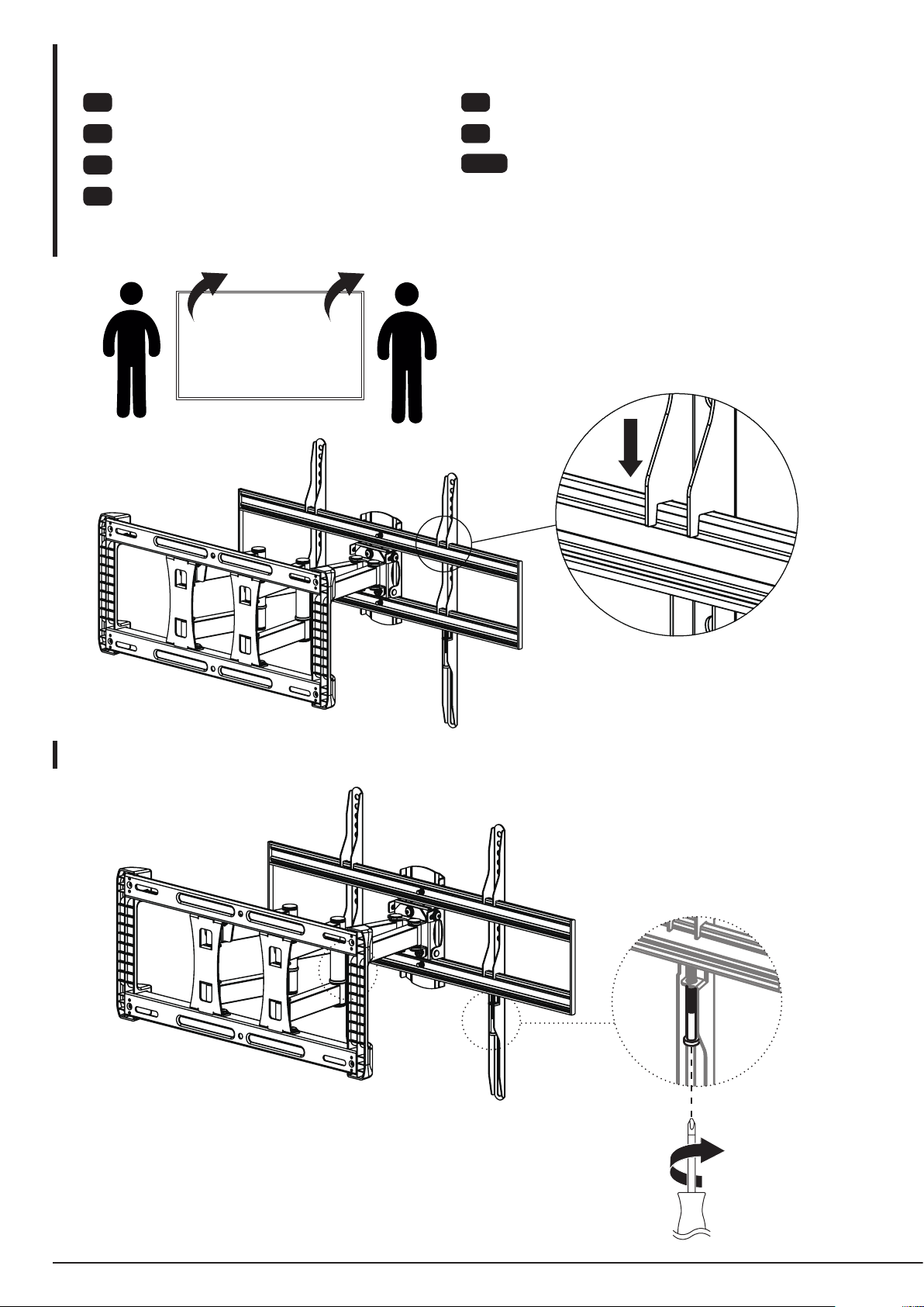
1:
TV
ES
Montaje Final
NL
Installatie
日本語
最終組み立て
2:
27
Page 16
3:
O
Assembly • Montage • Montage • Montaggio • Montaje • Montage • 組み立て
EN
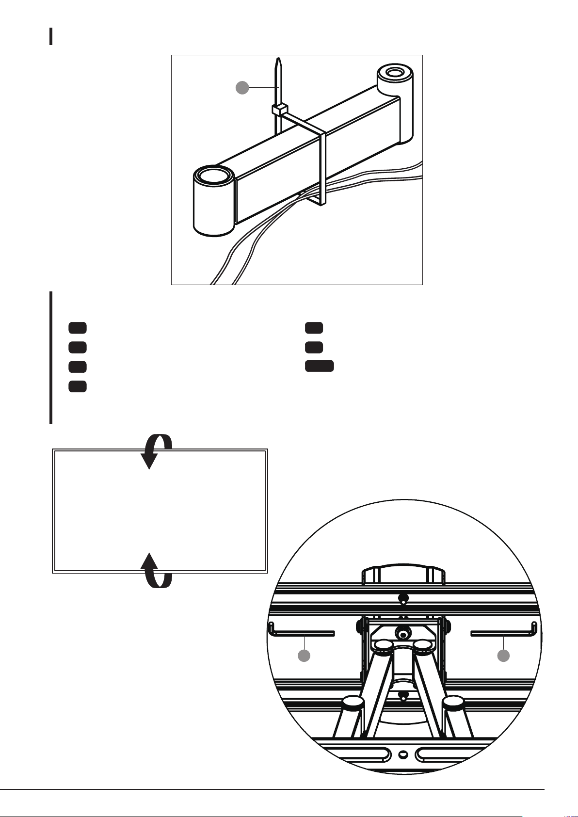
Operation and Adjustment
FR
Utilisation et Réglage
DE
Bedienung und Anpassung
IT
Funzionamento e Regolazione
1:
TV
ES
Funcionamiento y Ajuste
NL
Gebruik en aanpassing
日本語
操作及び調整
28
N N
Page 17
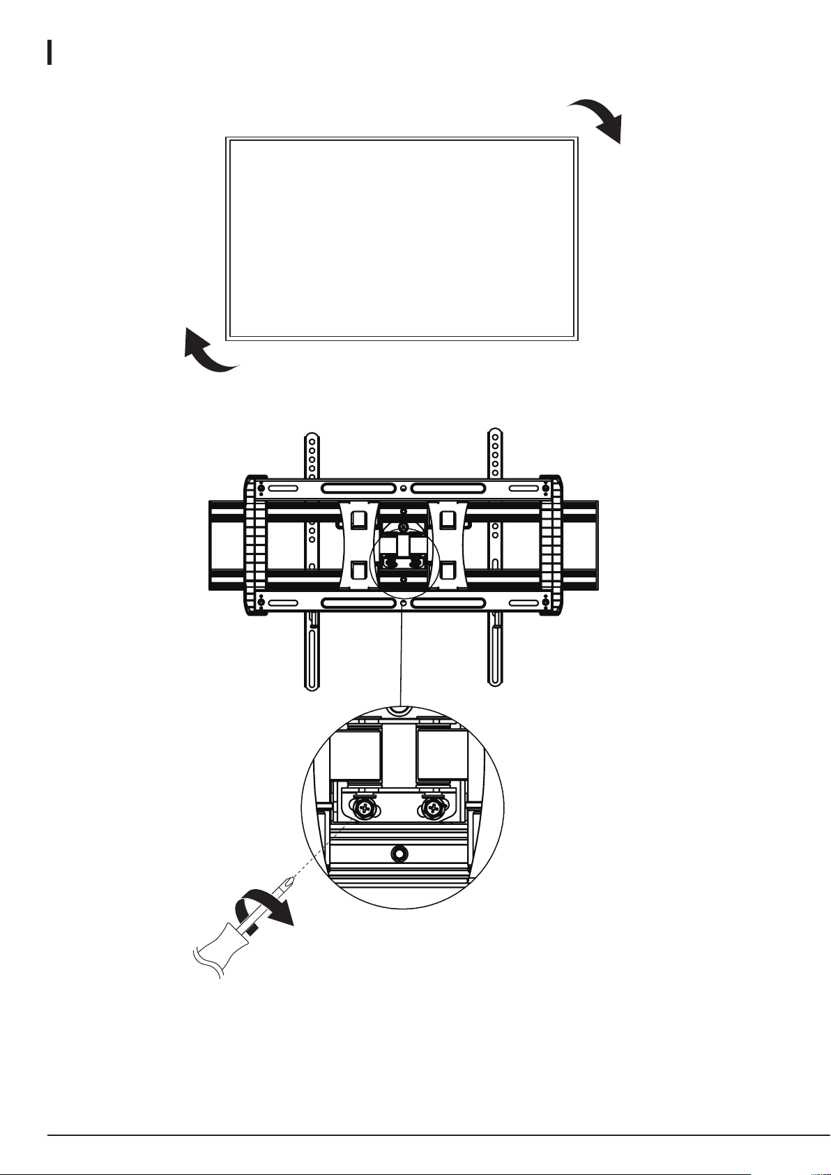
2:
TV
29
Page 18

MADE IN CHINA
FABRIQUÉ EN CHINE
HERGESTELLT IN CHINA
amazon.com/AmazonBasics
PRODOTTO IN CINA
HECHO EN CHINA
GEMAAKT IN CHINA
中国製
V1-05/19
 Loading...