

Page 1
’
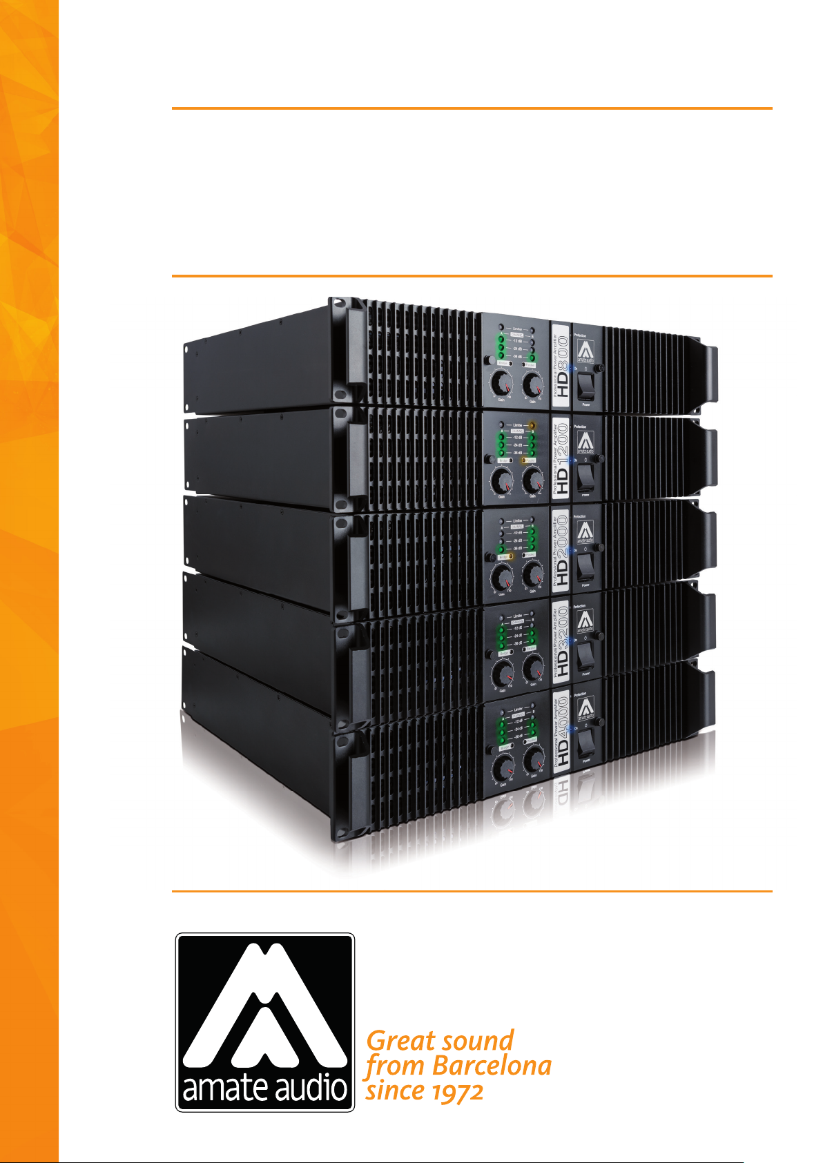
HD series
High Dynamics Professional Power Amplifi ers
Amplifi cadores profesionales de alta dinámica
Page 2

2
Page 3
EN
ENGLISH
In view of the fact that the requirements of audio professionals are
increasingly greater, we would like to thank you for choosing a AMATE
AUDIO product. At Amate Audio S.L., we have incorporated the highest
technology into our products with the conviction that what you have
purchased will give you an optimum performance and operation, however adverse the working conditions to which you may submit it.
In order to achieve the best performance and correct operation, it is
important that you read the instruction manual carefully before making
any connections.
In addition, we recommend that you read the Warranty Certificate
enclosed with this Manual in case you may observe any anomaly prior to
or immediately after start up, and how to proceed on each case.
1. General features
Our amplifiers are modular in design. The rigid metal chassis provides easy access to the electronic circuits. Fully independent safety
circuits protect the amplifier in the event of a short circuit of the loudspeaker output, abnormal increases in temperature and/or excessive
amplifier consumption.
INDEX
1. GENERAL FEATURES
2. FRONT PANEL FEATURES
3. INTERNAL FRONT PANEL FEATURES
4. REAR PANEL FEATURES
5. CONNECTION TO THE MAINS
6. CONNECTION OF THE LOUDSPEAKERS
7 WARNINGS
8. PRE-AMP CONNECTION
9. OPERATION MODE
10. COOLING
11. START-UP AND OPERATION
12. CLIP-LIMITER CIRCUIT
13. ADJUSTAMENT LIMITER
14. PROTECTIONS
15. TECHNICAL FEATURES
ENCLOSED DOCUMENT: CERTIFICATE OF WARRANTY
The power modules are integrated in a tunnel-shaped own developed heat sink, which combines high dissipation power with an
excellent thermal inertia, thanks to the high extraction effectiveness
of the incorporated fans.
The HD Series amplifiers offer high dynamic performance with
moderate average energy consumption, as well as good damping factor,
which results in clean response to transients and high quality playback.
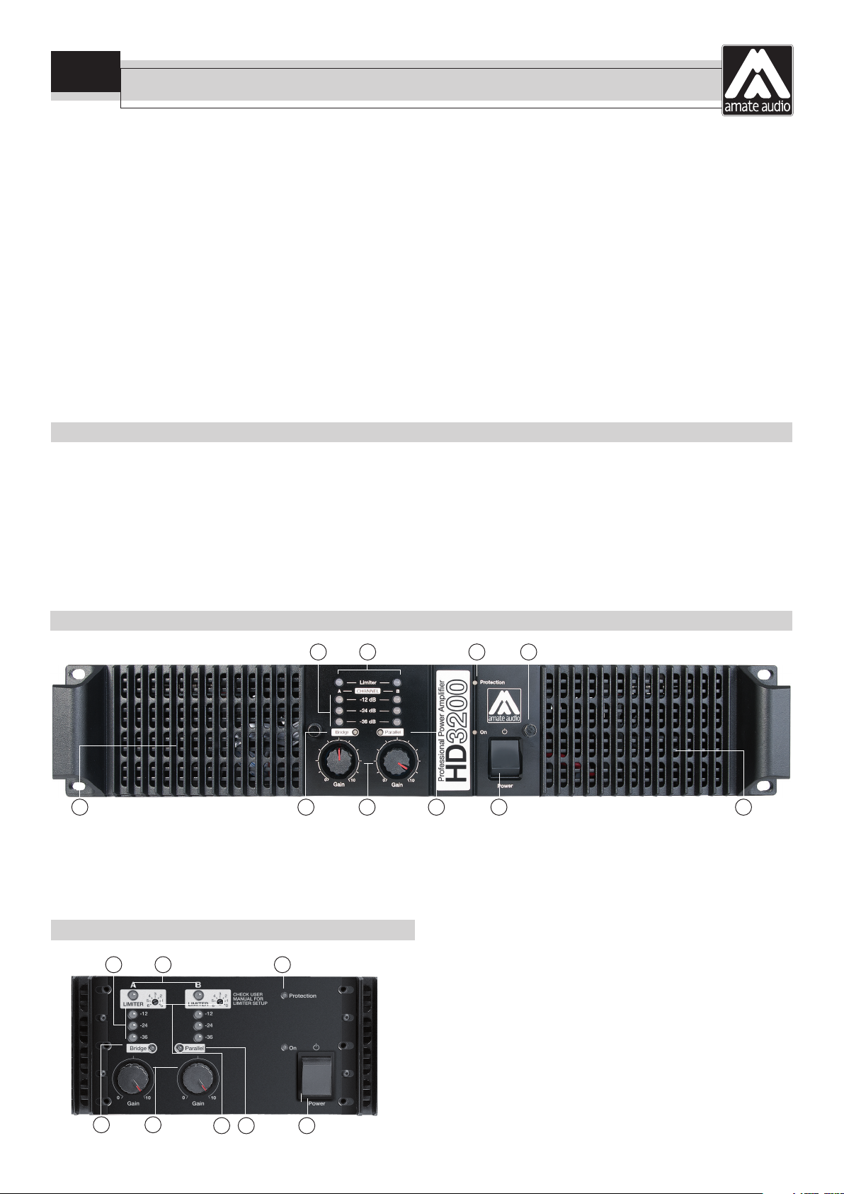
2. Front panel features
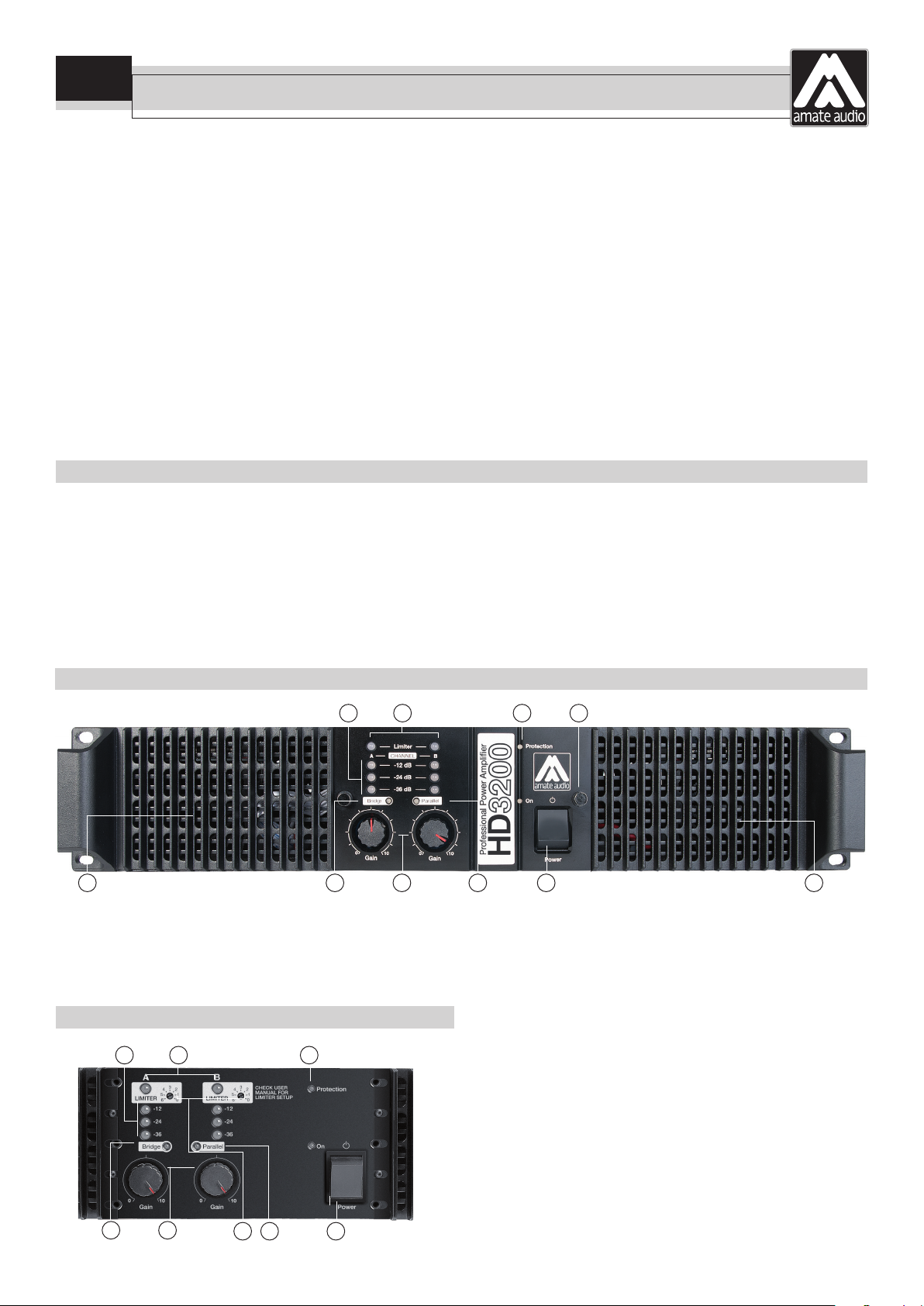
3 4 5 9
8 6 2 7 1 8
1) Power Switch – On-Off switch with Led
2) Volume Controls – Potentiometers to independently control the output
level for each channel.
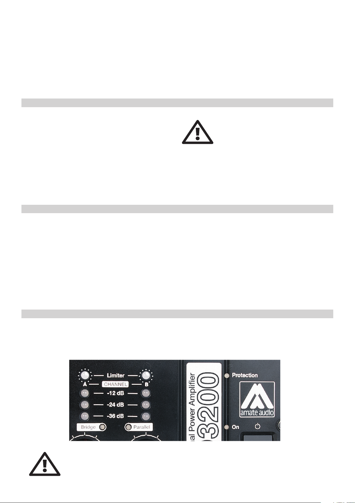
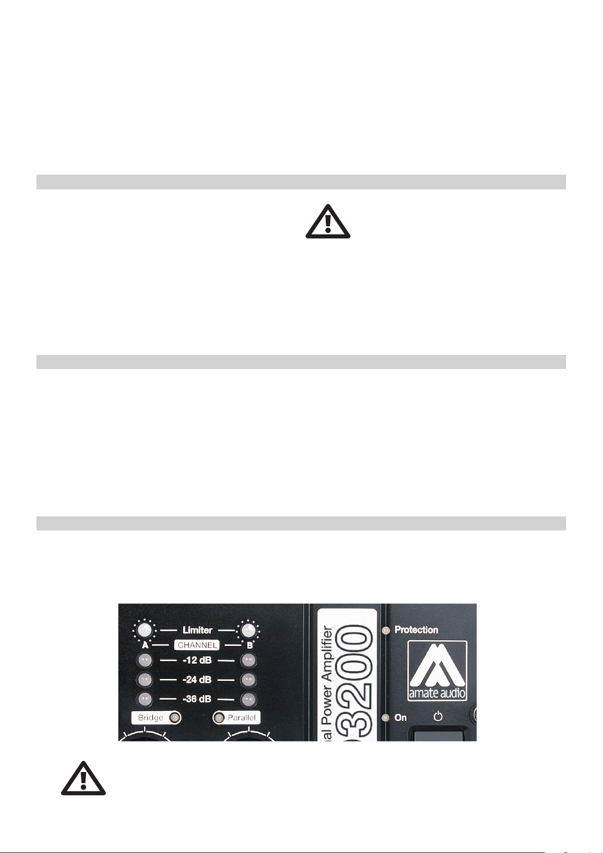
3) VU-Meters – Independent output signal indicators, with Leds for different
relative levels: -36dB, -24dB & -12dB.
3. Internal view ( Front panel out )
3 4 5
4) Limiter – Led indicating the operation start of the anti-clipping or limiter
systems.
5) Protection – Led indicating the operation of any of the protection system
of one or both channels. At power up normally it will turn ON momentarily.
If it does not turn OFF, indicates a problem of malfunction of the amplifier.
6) Bridge mode – Led indicating the bridge mode.
7) Parallel mode – Led indicating parallel mode.
8) Cooling outs – Forced air output for temperature regulation.
9) Panel screws – Detach (no tools needed) to access the internal panel.
6 2
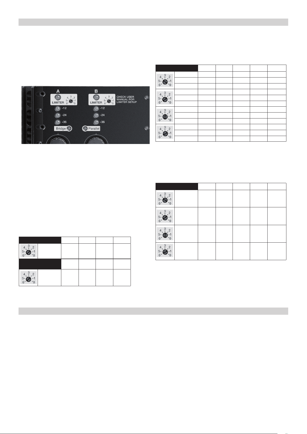
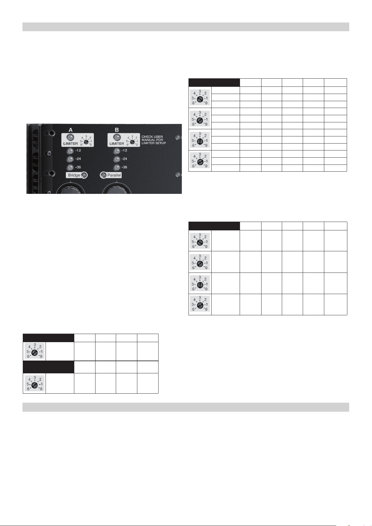
10) Limiter adjust – Easy adjustment for the limiter threshold of each output.
For more information see Section “Limiter Adjustment”.
7 110
3www.amateaudio.com
Page 4
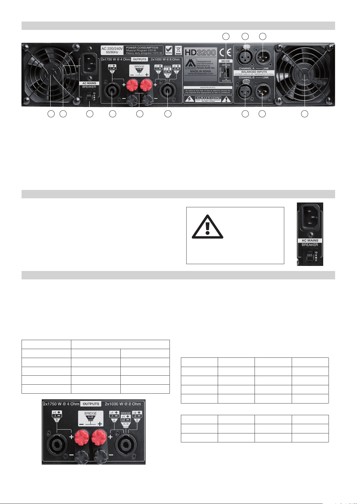
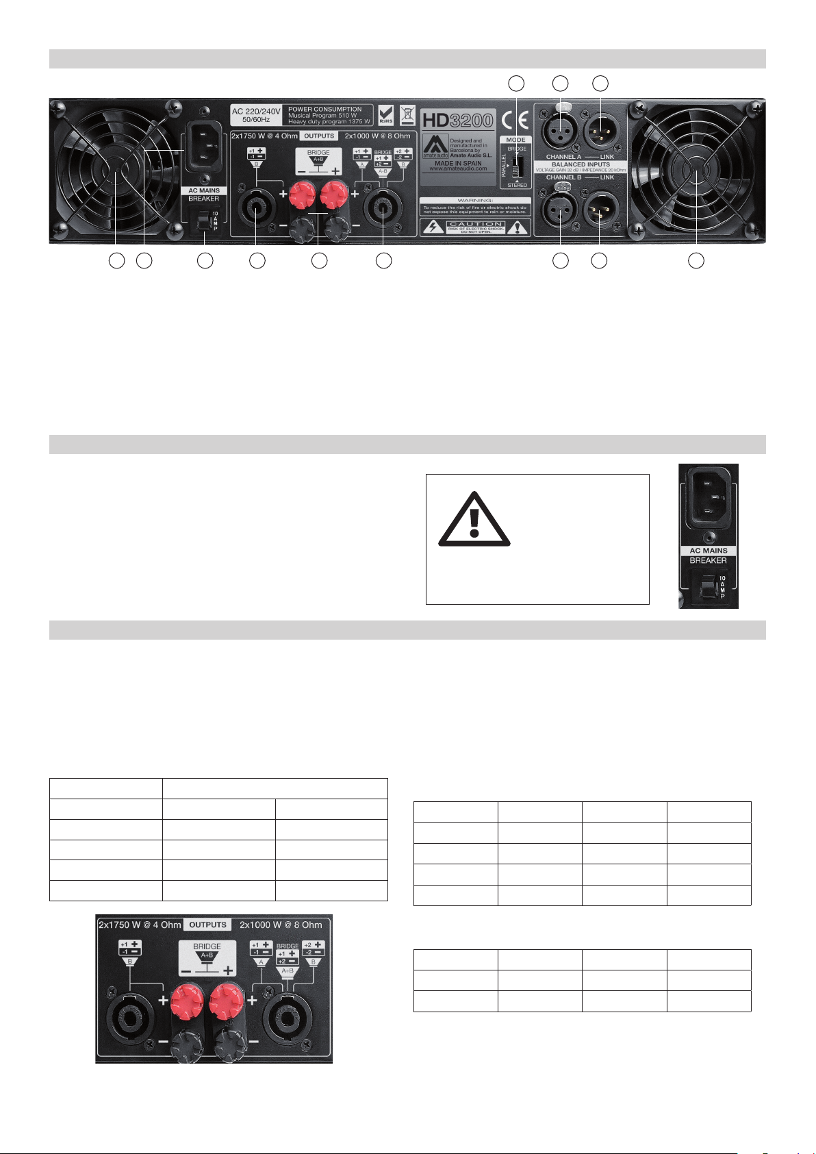
4. Rear panel features
3 1 2 11 10 39 6 7
8 4 5
1) IEC power connector – Input power supply 230V AC.
2) Breaker – Overcurrent protection.
3) FANS – Forced ventilation turbines. Do not cover.
4) XLR Input A – Electronically balanced for channel A.
5) XLR Link A – Signal link of the A channel (for another amplifier).
6) XLR Input B – Electronically balanced for channel B.
7) XLR Link B – Signal link of the B channel (for another amplifier).
8) Mode selection – Switch: Stereo, Bridge and Parallel mode.
5. Connection to the mains
First, it is essential to ensure that the main voltage corresponds to
the apparatus voltage. It is not advisable to connect and disconnect the
mains wire without first making sure that the switch is in its OFF position.
The amplifier is equipped with an Inrush current limiter circuit,
which avoids current excess when powering up. In addition to that, a
breaker switch located close to the IEC socket protects the amplifier
when the average current consumption is out of the specified range.
6. Connection of the loudspeakers
The loudspeaker system should be connected to the Speakon or
binding posts connectors ensuring that the polarity is correct. It is
very important to use a cable fitting to the power of the amplifier in
order to maintain the high damping factor these units provide.
9) Speakon Output A – Loudspeaker output A connection via 2-pole
Speakon (+1 -1) or loudspeaker output A+B (A: +1 -1; B: +2 -2) connection
via 4-pole Speakon.
10) Binding Posts – Separate outputs of each channel. This connector
is connected in parallel with the Speakon Output and they are recommended when requiring separate ways or a wire section greater that the
Speakon Output.
11) Speakon Output B – Loudspeaker output B connection via 2-pole
Speakon (+1 -1).
AC 220/240 V – 50/60 Hz
AVERAGE CURRENT DRAW
3 A at 1/8 power
6 A at 1/3 power
CAUTION: the connection to any other
voltage different from the one specified can
damage the amplifier immediately.
The Speakon connector (not included) has 4 terminal poles labeled
as +1, -1, +2 and -2. Each pole can fit a maximum wire section of 4mm2
(12AWG). In mobile applications this connection may also be soldered to
guarantee better contact.
As a general guideline, we offer a table showing the recommended cable section for different cable length, in order to keep power and
damping factor loss in acceptable values.
Max. recommended cable length
Cable Section 8 Ohm Load 4 Ohm Load
2.5mm2 (AWG14) 20 m 10 m
4mm2 (AWG12) 30 m 15 m
6mm2 (AWG10) 40 m 20 m
8 mm2 (AWG 8) 50 m 25 m
The Binding Posts are marked with Red for the Positive Pole, and
Black for the Negative Pole. They accept direct cable connection up to
8mm2 section (8AWG).
The outputs are configured as following for the STEREO and PARALLEL amplifier modes:
Output Speakon A Speakon B Binding Post
+ Ch A 1 + N.C. Red (A)
- Ch A 1 - N.C. Black (A)
+ Ch B 2 + (*) 1 + Red (B)
- Ch B 2 - (*) 1 - Black (B)
For BRIDGE mode, the following output connection is needed:
Output Speakon A Speakon B Binding Post
+ Pole 1 + N.C. Red (A)
- Pole 2 + N.C. Red (B)
(*) Although it is possible to get the output of both channels with the
same connector (Speakon A) when not strictly necessary, it is recommended whenever possible to use one Speakon connector for each output (Speakon A for CHA, Speakon B for CHB). With only two active pins
There are two speaker outputs: CH A and CH B both fitted with
Speakon sockets and Terminal type (binding posts) connectors.
4 User's Manual / Manual de usuario
+1 y -1 to avoid undesired signal crosses between positive pins that can
damage the amplifier.
Page 5
7. Warnings
CAUTION high risk of malfunction or mayor damage!
As specified in the previous point, there is the posibility to have both
channel outputs (A and B) through the SPEAKON A, this function is very
useful when using the amplifier in BRIDGE mode, this is posible because
the SPEAKON A uses all the pins (+1 -1 belong to channel A and +2 -2
to channel B).
BE CAREFUL WHEN USING THIS KIND OF CONNECTION, A
SHORTCIRCUIT BETWEEN THE POSSITIVE PINS (+1 +2) CAN DAMAGE THE AMPLIFIER OR EVEN THE DESTRUCTUTION OF ONE, OR
BOTH, POWER MODULES THIS IS BECAUSE A SHORTCIRCUIT BETWEEN POSITIVE PINS MAKES ONE CHANNEL WORKS AGAINST
THE OTHER
8. Pre-amp connection
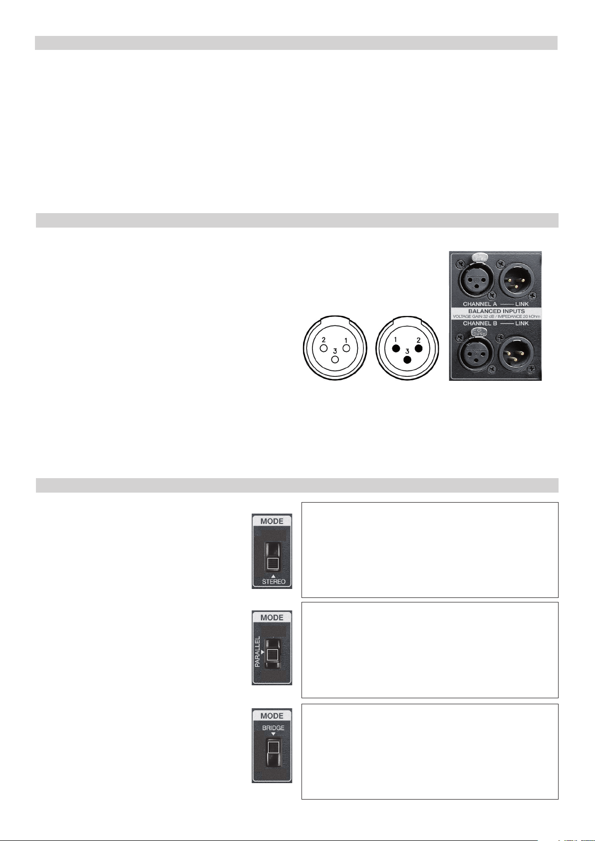
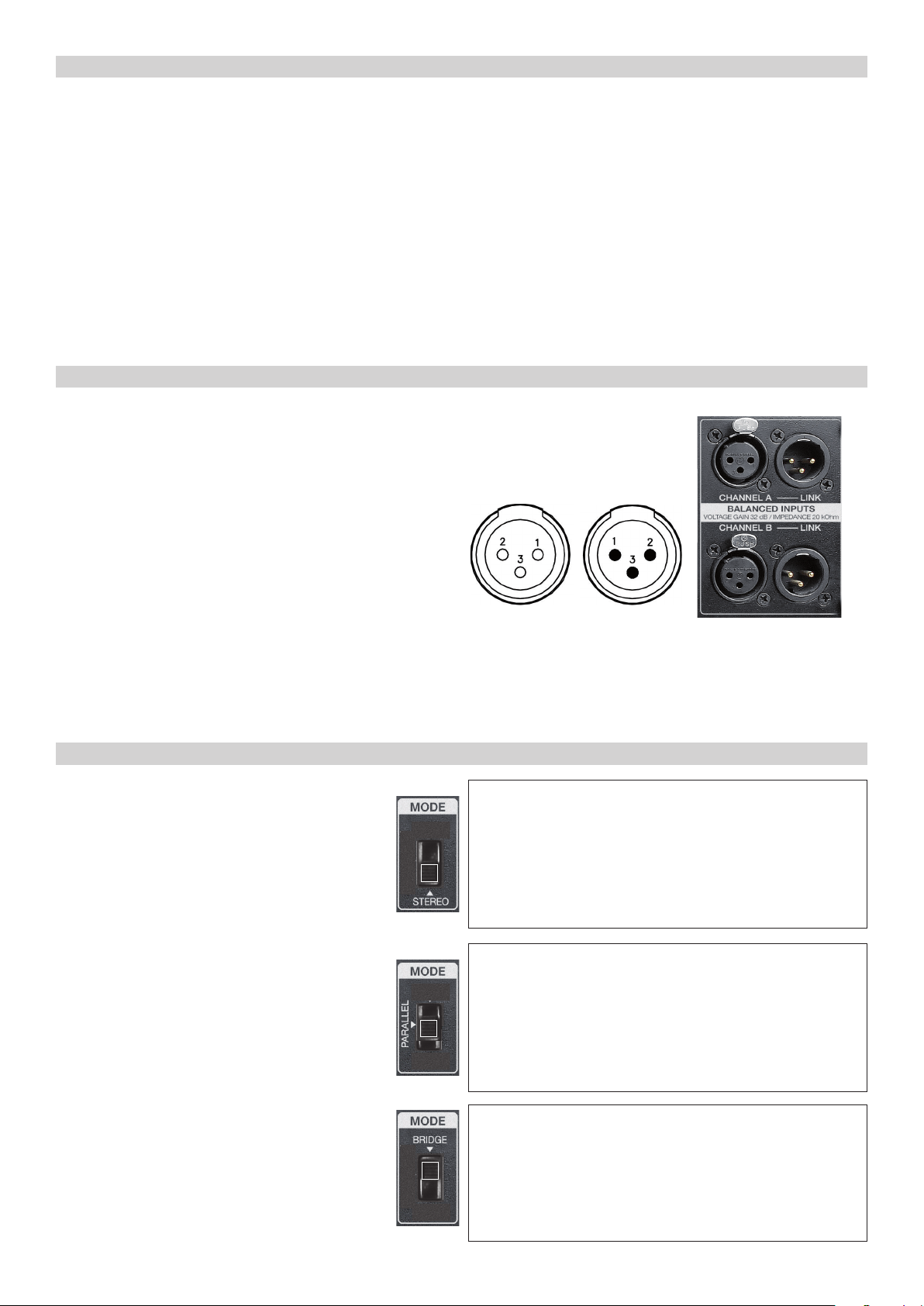
The input (BALANCED INPUTS) enables connection through XLR-3
connectors. The amplifiers incorporate balanced input for a high rejection of noise generated by long signal cables, proximity to electric
wires or sources causing them.
BALANCED Inputs/auxiliary outputs:
1. Shield
2.(+) Live
3. (–) Return
UNBALANCED Inputs/auxiliary outputs:
1. Not connected (* See Note)
2. (+) Live
3. Ground
Load Capacity: The HD amplifiers have a sufficient current capacity
to admit very low loads (down to 2 Ω). It should be taken into account
that many loudspeakers using passive filters and whose nominal impedance is of 8 Ω do in fact present impedance much lower than the
nominal one at certain frequencies. Therefore, it is advisable to use
2 Ω loads only when one is perfectly aware of the impedance curve
of the loudspeaker system to be connected. Otherwise, the amplifier
could cause cut-offs at the output due to the short circuit protection
(low impedance, <2 Ω) or over heating.
For lower nominal impedance connections (2 Ω STEREO/PARALLEL;
4 Ω BRIDGE) see section 13. Limiter adjustment.
(*) NOTE: This amplifier follows the ground interconnection specification
defined by AES48-2005 standard of the Audio Engineering Society, on
grounding and EMC practices for audio equipment containing active circuitry.
For that reason, when a source with unbalanced outputs should be connected, it is recommended not to use Pin1 of the XLR, and never connect it to
9. Operation modes
Stereo
In Stereo mode, each one of the amplifier channels
works independently from the other.
Parallel
In this mode, the signal inserted at CHA input will be
routed to both channel’s power modules (CHA and
CHB), ignoring the signal at CHB input. This option is
useful when a series of speakers must be fed with the
same signal, because the signal can be routed saving extra cable connections between inputs.
Pin3. If a shielded cable is available, the shield may be connected to Pin1
of the XLR to get some shielding, leaving the other end unconnected. Pin1
connection is only advised if the equipment with the unbalanced output
has a dedicated connection for the shield, separate from the audio signal
ground reference.
To use Stereo Mode, make sure that the MODE selector,
located next to the input section (BALANCED INPUTS) is in the
STEREO position (down).
Features:
* Independent input for each channel
* Independent volumen for each channel
* Independent limiter adjustment for each channel
* Independent anti-cliping system for each channel
To use Parallel Mode, place the MODE selector switch in PARALLEL position. The corresponding indicator located on the front
panel will light up (PARALLEL).
Features:
* One input for both channels (CH. A)
* Independent volumen for each output
* Independent limiter adjustment for each output
* Independent anti-cliping system for each ouput
Bridge (Mono)
In this position both channels are used as a single amplifier, capable of delivering the double of the power. In this
operational mode the input signal must be fed through
CHA input connector. At the output, connections must
be made as following:
To use Bridge Mode, place the MODE selector switch in Bridge
position. The corresponding indicator located on the front panel
will light up (BRIDGE).
Features:
* One input (CHA)
* One volumen control(CHA)
* One limiter adjustment ( CHA)
* Anti clipping system (CHA or CHB)
5www.amateaudio.com
Page 6
The + Pole of the speaker is connected to the Speakon Pin +1 of CH A, or
the Red terminal of the CH A. The – Pole of the speaker is connected to
the Speakon Pin +2 of CH A, or the Red terminal of the CH B.
IMPORTANT: The recommended load impedance for bridge mode is
8 Ω. If the load impedance is 4 Ω, each power module will work at an
effective impedance of 2 Ω, and therefore permanent installations are
discouraged in these conditions (see “Warnings” section 7). Please check
the specifications table to learn the delivered power in Bridge mode.
10. Cooling
CAUTION: In this situation, it could be dangerous to handle the connections by non-authorized personnel, due to manipulation of high voltage.
The HD Series are equipped with electronically controlled forced
ventilation, which is carried out by two turbines situated at the rear panel, one in front of each power module. According to the temperature,
two different fan speeds are set, and the hot air is evacuated through
the front panel. It is very important to favor the good air circulation to
keep the equipment in a stable temperature work pattern; therefore any
possible obstruction must be avoided both in the rear and front part. In
addition, an installation close to heat generator sources or lack of ventilation must be avoided (closed cabinets).
11. Start-up and operation
Once the mains, loudspeaker and sound sources (input) connections have been made correctly, start up the pre-amp sources and then
press the ON/OFF switch. Turn the volume controls clockwise to obtain
the maximum gain.
The amplifier is equipped with a Soft Start circuit, which assures a
gentle, pop free start up, avoiding stress to the loudspeakers.
In order to obtain the maximum dynamic range from the amplifier,
it is recommended to set always the gain controls to the maximum, and
WARNING: As the forced air circulation (from the
back to the front) can produce the introduction of dust
and dirt in general over the internal radiators, it is highly recommended to make an internal cleaning operation
at least once a year, depending on the particular circumstances of each installation or use.
Any deterioration of the amplifier caused by an evident
presence of dust and/or internal humidity, will EXCLUDE of any right of application of the Warranty for
this product.
control the output power by regulating the signal level at the amplifier’s
input using the processor gain control (in this condition of the gain controls to the maximum, the amplification is fixed at 32dB per channel).
When the maximum output power has been reached in any of both
channels , this will be indicated by the corresponding led LIMITER, advising that it is recommended to lower the general volume coming from
the mixer our sound source connected to that channel (previous crossover, equalizer, processor, etc.).
12. Clip / Limiter
This circuit prevents the amplifier from delivering distortion at the
loudspeaker outputs. Its action is practically inaudible and protects the
loudspeaker voice coils. A LED on the front panel indicates the action of
WARNING: Make sure the LED LIMITER is not alight permanently!
No extra power is obtained in this way, loosing dynamics and sound quality.
the anti-clipping limiter of each channel. If the clip LED is lit intermittently, this may be interpreted as correct, but it means that the amplifier
is reaching its maximum power at this point.
6 User's Manual / Manual de usuario
Page 7
13. Limiter adjustment
The 2014 version HD amplifiers feature limiter adjustment, in which
the user, with an easy adjust, can limit the output power of each output
independently. It is an easy access adjustment and it is located behind
the front panel.
The front panel is fixed with two M4 screws with knurled head that
can be loosen with the fingertips. After removing the front panel you
will find two LIMITER sections, one per channel, they can be adjust with
a small flat-tip screwdriver.
The factory setting for this parameter is set to fully clockwise, this
way the device delivers its maximum power with minimum distortion
thanks to its anti-clipping system.
Once the limiter settings have been adjusted, please attach again
the front panel with the two M4 screws with knurled head.
STEREO PARALLEL:
In STEREO/PARALLEL mode each channel have an independent limiter adjustment; see the attached table of the delivered output deppending of the limitrer adjustment:
STEREO/PARALLEL MODE
16 Ω 115 W 210 W 350 W 650 W 390 W
8 Ω 230 W 420 W 700 W 1300 W 750 W
0
4 Ω 450 W 800 W 1300 W 2400 W 1480 W
16 Ω 76 W 110 W 150 W 320 W 250 W
2
8 Ω 152 W 220 W 300 W 600 W 475 W
4 Ω 295 W 410 W 550 W 1100 W 975 W
3
6
16 Ω 50 W 70 W 90 W 180 W 180 W
8 Ω 100 W 140 W 180 W 320 W 375 W
4 Ω 195 W 280 W 350 W 625 W 725 W
16 Ω 25 W 38 W 50 W 100 W 95 W
8 Ω 50 W 76 W 100 W 200 W 190 W
4 Ω 95 W 135 W 200 W 400 W 380 W
HD800 HD1200 HD2000 HD3200 HD4000
BRIDGE:
In BRIDGE mode the limiter adjusment is the one for channel A, the
same with the volume adjust, see attached table of the delivered output
power depending on the limiter adjustment:
OUTPUT POWER TO LIMITER SETTING
LOW LOAD
(BRIDGE 4 Ω or STEREO/PARALELL 2 Ω)
:
CAUTION: when you want to use the amplifier in bridge mode @ 4 Ω
or Stereo/parallel mode @ 2 Ω at full power it is recommended to set
the limiter in position 2 as shown in the attached table to avoid overheating. (Only HD4000 is ready to work on any position)
BRIDGE MODE 4 Ω
2
BRIDGE
MODE 4 Ω
STEREO/PARALLEL MODE
2 Ω
STEREO/
2
PARALLEL
MODE 2 Ω
HD800 HD1200 HD2000 HD3200
1180 W 1640 W 2200W 4400W
HD800 HD1200 HD2000 HD3200
590 W 820 W 1100 W 2200 W
14. Protections
Temperature
An inadequate installation or any other anomaly related to cooling may
cause that the amplifier’s temperature exceeds their safe limit (>90ºC),
exposing its internal components to failure. The temperature protection
would activate the corresponding limiters to reduce (balance) the output
power with the overtemperature, in order to keep the amplifier working
safely without undesirable stops. In case the temperature keep rising, the
corresponding protection circuit will cause a stop during a certain time
according to the seriousness of the anomaly detected. The PROTECTION
and LIMITER leds will light on at the same time, and the output of the
affected channel(s) will be disconnected.
In models HD2000 and HD3200, before the amplifier completely stops
because of temperature problems, it will reduce the output level by 6dB
approximately. Once the temperature reduce to normal parameters, the
normal output level will be reestablished.
BRIDGE MODE 8 Ω
0
2
3
6
8 Ω 900 W 1600 W 2800 W 4800 W 2450 W
8 Ω 590 W 820 W 1100 W 2200 W 1132 W
8 Ω 390 W 540 W 700 W 1250 W 850 W
8 Ω 190 W 270 W 400 W 800 W 500 W
HD800 HD1200 HD2000 HD3200 HD4000
4200 W(4Ω)
1950 W (4
1450W (4
760 W (4
Ω)
Ω)
Ω)
Note (1): The limiter adjustments and power that the amplifiers can deliver with
this adjustment are relative, because the HD amplifiers feature a dynamic limiting
system able to offers the best results.
The conditions to get the data from the tables has been created using 100 Hz
sineburst input signals with 100 ms at 0 dB and 400 ms at -20 dB. This condition is
considered as a standard / heavy duty in the Audio Industry.
Short circuit
In case of very low impedance or short circuit in any loudspeaker output, the LIMITER led is activated and a significant descent of the output
level of the affected channel will be observed (loss of volume, but keeps
working).
Direct Current
In the case that due to some malfunction the power module tries to deliver direct current (DC) at the output, the protection circuit will imme-
diately disconnect the module to avoid damage to the loudspeakers. In
that case, the PROTECTION and LIMITER led’s will light on at the same
time and the output will be disconnected.
7www.amateaudio.com
Page 8
Other causes that could prevent the normal work of the amplifier can
also activate the PROTECTION. Under those circumstances, the installa-
- Short circuit: Check the state of the loudspeaker line (possible
short circuit, disconnect and check if the anomaly disappears).
tion has to be revised according to the basic principles described below:
- C.C. at the output (DC): Possible serious breakdown. Contact an
- Disconnect all the connected peripheral equipments (sources,
authorized technical service.
pre-amplifiers, and loudspeakers). Leave the amplifier “alone” and verify
if the anomaly disappears or if it remains in only one channel or both.
In all cases it is recommended to go through all previous checkpoints
before contacting the authorized technical service and reporting the
- Temperature: Cooling (possible air obstruction. Check if the fans
observed problem.
are working and make an internal cleaning).
15. Technical features
HD800 HD1200 HD2000 HD3200 HD4000
Voltage Gain
Input Sensitivity 1 V 1.25 V 1.74 V 2 V 1.88 V
Input Impedance 20 kΩ
Slew Rate +/-12 V/μs
Output Power (1 kHz - 0,1% THD)
1
Stereo 8 Ω 230 + 230 W 350 + 350 W 600 + 600 W 1000 + 1000 W 650 + 650 W
Stereo 4 Ω 400 + 400 W 600 + 600 W 1000 + 1000 W 1750 + 1750 W 1200 + 1200 W
Stereo 2 Ω
1
550 + 550 W² 850 + 850 W² 1500 + 1500 W² 2500 + 2500 W² 2100 + 2100 W³
Bridge 8 Ω 800 W 1200 W 2000 W 3500 W 2840 W
Bridge 4 Ω
Average Current draw 4
1
1100 W² 1700 W² 3000 W² 5000 W² 4200 W³
3 A @ 230 V AC 4 A @ 230 V AC 5 A @ 230 V AC 6 A @ 230 V AC 7 A @ 230 V AC
Frequency Response 20 Hz - 20 kHz (0/-1 dB)
Damping Factor (1 kHz @ 8 Ω) 280 300 350 400 350
Crosstalk 60 dB 65 dB
S/N Ratio (A-weighted) 102 dB (A) 104 dB (A) 105 dB (A) 108 dB (A) 108 dB (A)
Mains 220 – 240 V AC- 50/60 Hz
Dimensions (HxWxD) 88 x 482 x 420 mm 88 x 482 x 420 mm 88 x 482 x 440 mm 88 x 482 x 440 mm 88 x 482 x 440 mm
Weight 14 kg 15 kg 18 kg 21 kg 21 kg
32 dB
Note (1): Continuous burst tone 20 ms (0 dB) / 480 ms (-20 dB) in accordance with EIA RS-490 and IEC 60268-3(IHF A-202).
Note (2): Driving the amplifier at 2 Ω channel / 4 Ω bridge at full power mode in poor ventilation conditions may cause a thermal overload protection.
2 Ω power is time limited by mains circuit breaker.
Note (3): Specifically designed for long term operation in bridge 4 Ω at full power.
Note (4): Heavy duty musical program.
Specifications subjected to change without prior notice (April 2016).
If you follow the instruction manual and recommendations, we are sure that this amplifier will always perform within the predetermined parameters, ensuring its long life and total efficiency.
Certificate of warranty (enclosed document)
The Conditions and Observations for the application of this Contract of Warranty are for all the territories
of Spanish.
For other countries, the specifications of each country must be complied with, as only the Representative
or National importer themselves can be held responsible for warranty terms.
For any claim of a Legal type, only the Ordinary Courts corresponding to the city of Terrassa (BarcelonaSpain) will be valid.
Please follow the instructions on the last page of this manual. Please READ the instructions and conditions
gathered in the Warranty Certificate to fully take advantage of the After-Sales Service.
8 User's Manual / Manual de usuario
Page 9
ES
ESPAÑOL
Amate Audio S.L. le agradece la confianza depositada en la compra de este amplificador. Deseamos informarle de que todos nuestros
productos incorporan las más avanzadas tecnologías en todo su proceso de fabricación, así como la más depurada selección de todos sus
componentes, lo que nos permite garantizarle un óptimo rendimiento y funcionalidad en cualquiera de las aplicaciones y condiciones de
trabajo a las que usted le someta.
No obstante y para obtener su máximo rendimiento y un correcto funcionamiento, es importante leer detenidamente el presente
manual de instrucciones antes de cualquier conexión. Asimismo le
recomendamos que lea también la Carta de Garantía adjunta a este
Manual por si observara cualquier anomalía previa o inmediata a su
puesta en marcha y como proceder en su caso.
1. Características Generales
El diseño de nuestros amplificadores de potencia es modular. El
chasis metálico de gran rigidez y el elaborado diseño interior, permiten un fácil acceso a los circuitos electrónicos. Los circuitos de
protección, totalmente independientes, protegen al amplificador en
el caso de un cortocircuito en la salida de altavoces, un incremento
anormal de la temperatura y/o un consumo excesivo del amplificador.
Los amplificadores HD Series poseen una muy elevada potencia
dinámica con un moderado consumo energético medio, además de
ÍNDICE
1. CARACTERÍSTICAS GENERALES
2. PANEL FRONTAL
3 . PANEL FRONTAL INTERNO
4. PANEL POSTERIOR
5. CONEXIÓN A LA RED
6. CONEXIÓN DE ALTAVOCES
7. ADVERTENCIAS
8. CONEXIÓN DE PREVIOS
9. MODOS de FUNCIONAMIENTO
10. VENTILACIÓN
11. FUNCIONAMIENTO Y PUESTA EN MARCHA
12. CLIP / LIMITER
13 AJUSTES LIMITADOR
14. PROTECCIONES
15. FICHA TÉCNICA
DOCUMENTO ADJUNTO CERTIFICADO DE GARANTÍA
un buen factor damping, lo que se traduce en una limpia respuesta
a transitorios y una reproducción de gran calidad. Los módulos de
potencia integrados en su correspondiente radiador-túnel, de diseño propio, aúnan un alto poder de disipación de calor con una excelente inercia térmica, gracias a la gran efectividad de extracción que
presentan los ventiladores incorporados.
2. Panel Frontal
3 4 5 9
8 6 2 7 1 8
1) Interruptor de puesta en marcha – Con Led indicador de “On”.
2) Control de volumen – Potenciómetros para ajustar el nivel independiente
de cada canal.
3) VU-Meters – Indicadores del nivel de salida independientes para cada canal,
con leds para indicar los niveles relativos de: -36dB, -24dB y -12dB.
3.Panel Frontal interno
3 4 5
4) Limitador – Led indicador de la función de limitador y anti-clipping.
5) Protección – Led que indica la activación de cualquiera de las protecciones
integradas, de uno o ambos canales. En la puesta en marcha es normal que se
ilumine brevemente. Si no se apaga, indica un problema en el amplificador.
6) Bridge mode – Led indica modo bridge.
7) Parallel mode – Led indica modo parallel.
8) Salidas de ventilación – Salidas de aire forzado para refrigeración del equipo.
9) Tornillos panel – Desenroscar (sin herramientas) para acceder al panel interno.
10)
Ajuste del limitador – Ajuste fácil del umbral del limitador para cada
canal. Para más información ver el Capítulo “Ajuste del Limitador”.
6 2
7 110
9www.amateaudio.com
Page 10
4. Panel Posterior
3 1 2 11 10 39 6 7
8 4 5
1) Conector de red IEC – Entrada de red 230VAC
2) Breaker – Protección de sobrecorriente.
3) VENTILADORES – Turbinas para la ventilación forzada. No cubrir.
4) Entrada XLR A – Balanceada electrónicamente para el canal A.
5) Salida XLR Link A – Link de señal canal A (para otro amplificador).
6) Entrada XLR B – Balanceada electrónicamente para el canal B.
7) Salida XLR Link B – Link de señal canal B (para otro amplificador).
8) Selección de modo – Conmutador: Stereo, Bridge y Parallel.
5. Conexión a la red
En primer lugar es necesario asegurarse de que el voltaje de red
corresponde al del equipo.
Es recomendable verificar que el interruptor de puesta en marcha
está en posición apagado. El amplificador está dotado de un circuito
“Soft-Start” de arranque suave, que limita excesos de corriente en la
puesta en marcha. Además, junto a la toma de corriente se encuentra
el interruptor Breaker, que protege al equipo en caso que el consumo
medio de corriente esté fuera de los parámetros normales.
6. Conexión de altavoces
El sistema de cajas acústicas debe conectarse al conector Speakon
o a los bornes, asegurándose de que la polaridad sea la correcta. Es muy
importante utilizar el cable adecuado a la potencia del amplificador para
mantener el elevado factor damping que estas unidades ofrecen.
A título orientativo, ofrecemos una tabla de valores de la sección
mínima recomendada dependiendo de la distancia, para mantener las
pérdidas de potencia y de factor damping en valores aceptables.
Longitud cable max. recomendada
Sección del cable Carga 8 Ohm Carga 4 Ohm
2.5mm2 (AWG14) 20 m 10 m
4mm2 (AWG12) 30 m 15 m
6mm2 (AWG10) 40 m 20 m
8 mm2 (AWG 8) 50 m 25 m
9) Conector Speakon A – Salida A para conexión de altavoces mediante
Speakon de 2 polos (+1 -1) o salida A+B para conexión de altavoces
(A: +1 -1; B: +2 -2) mediante Speakon de 4 polos.
10) Bornes – Salidas separadas para cada canal, conectadas en paralelo
con las salidas Speakon. Se recomienda utilizar los bornes en caso que se
necesiten cables de sección más elevada que la que admite el Speakon.
11) Conector Speakon B – Salida B para conexión de altavoces mediante
Speakon de 2 polos (+1 -1).
AC 220/240 V – 50/60 Hz
AVERAGE CURRENT DRAW
3 A at 1/8 power
6 A at 1/3 power
PRECAUCIÓN: La conexión a un voltaje diferente del especificado puede dañar inmediatamente al amplificador.
El conector Speakon necesario (no suministrado con el aparato),
dispone de 4 puntos de conexión denominados +1, -1, +2, -2 y admite
un máximo de 4 mm2 de sección (12AWG). Para aplicaciones móviles se
recomienda soldar el contacto para asegurar su fijación.
Los Bornes están marcados con el color Rojo para el polo positivo
del altavoz y con el color Negro para el polo negativo. Aceptan conexión
directa de cable hasta 8mm2 de sección (8 AWG).
Las salidas están configuradas de la siguiente manera para el modo
STEREO o PARALLEL:
Output Speakon A Speakon B Binding Post
+ Ch A 1 + N.C. Red (A)
- Ch A 1 - N.C. Black (A)
+ Ch B 2 + (*) 1 + Red (B)
- Ch B 2 - (*) 1 - Black (B)
Para el modo BRIDGE, utilizar el Speakon A o los Bornes, con la siguiente
configuración:
Output Speakon A Speakon B Binding Post
+ Pole 1 + N.C. Red (A)
- Pole 2 + N.C. Red (B)
(*) Aunque es posible obtener la salida de los dos canales a través de
un mismo conector (Speakon A), se recomienda siempre que sea posible utilizar un conector Speakon para cada salida (Speakon A para CHA,
Speakon B para CHB); con solo dos polos activos +1 y -1 para poder rea-
Se dispone de dos salidas para altavoces. Canal A y Canal B, provistas
de una base para conector Speakon, y un par de Bornes para cada una.
10 User's Manual / Manual de usuario
lizar conexiones libres de cruces entre los polos positivos y de esta manera evitar posibles problemas y averías.
Page 11
7. Advertencias
ATENCIÓN ¡ALTO RIESGO DE MALFUNCION O AVERÍA¡
Según lo especificado en la configuración conexiones de altavoces;
existe la posibilidad de obtener la salida de ambos canales del amplificador en el SPEAKON del canal A, esta función es especialmente útil
cuando se esta trabajando en el modo “Bridge”, esto es posible por que
se utiliza todas las salidas de este conector (las salida +1 -1 corresponden
al canal A y las salidas +2 -2 corresponden al canal B)
ROGAMOS SE TENGA ESPECIAL PRECAUCIÓN AL UTILIZAR ESTE
TIPO DE CONEXIONADO, UN CRUCE ENTRE LOS POLOS POSITIVOS
(+1 Y +2) PUEDE PROVOCAR UNA MALFUNCION, DAÑAR AL AMPLIFICADOR O OCASIONAR GRAVES AVERÍAS COMO LA DESTRUCCIÓN DE UNO, O AMBOS MODULOS DE POTENCIA DEBIDO A QUE
UN CRUCE ENTRE LOS POLOS POSITIVOS HACE TRABAJAR UN CANAL
CONTRA EL OTRO
8. Conexión de previos
Las entradas (BALANCED INPUTS) permiten la posibilidad de conexión mediante XLR-3. Los amplificadores, incorporan entradas balanceadas para un elevado rechazo de los parásitos generados por cables de
señal largos o cercanos a cables eléctricos o fuentes que los provoquen,
y garantizar así, una perfecta respuesta en frecuencia.
Entradas y salidas BALANCEADAS:
1. Malla
2. (+) Vivo
3. (–) Retorno
Entradas y salidas NO BALANCEADAS:
1. No conectar (*ver nota)
2. (+) Vivo
3. Malla
Capacidad de carga: Los amplificadores HD Series tienen capacidad de
corriente suficiente para aceptar cargas muy bajas (hasta 2 Ω). Hay que
tener en cuenta que muchos altavoces de impedancia nominal 8 Ω que
utilizan filtros pasivos, a ciertas frecuencias presentan impedancias mucho más bajas de la nominal, por lo tanto, es recomendable usar cargas
de 2 Ω solo cuando se conoce perfectamente la curva de impedancia
de los sistemas de altavoces a conectar. En su defecto, el amplificador
podría provocar cortes en la salida por cortocircuito (baja impedancia, <2
Ω) o por sobre calentamiento.
Para conexiones de cargas inferiores a las nominales ver sección 13, ajustes de limitador
(*) NOTA: Este equipo sigue el esquema de conexionado de masas especificado por el estándar AES48-2005 de la Audio Engineering Society, sobre
interconexiones de equipos de audio con circuitos activos.
Por este motivo, cuando se desea conectar una salida no balanceada al amplificador se recomienda no utilizar el Pin 1 del XLR, y en ningún caso co-
9. Modos de funcionamiento
Stereo
En este modo cada uno de los canales del amplificador
funciona independientemente del otro
Parallel
Esta función envía la señal introducida en la entrada del
CHA a los dos módulos de potencia (CHA y CHB), ignorando la señal introducida en la entrada del CHB. Esta opción es interesante en el caso de que el amplificador se
utilice para alimentar varios altavoces con la misma señal,
ya que elimina la necesidad de realizar interconexiones
entre canales.
nectarlo con el Pin 3. Si se utiliza cable mallado se puede conectar un ex-
tremo de la malla al Pin1 del XLR y dejar el otro extremo sin conectar para
conseguir cierto apantallamiento. La conexión del Pin 1 se recomienda
únicamente si el equipo con la salida no balanceada tiene una conexión
específica para la malla (tierra), separada de la masa o referencia de señal.
Para seleccionarlo, asegurarse de que el Selector de MODE, situado junto a la sección de Entradas (BALANCED INPUTS), se encuentra en la posición STEREO.
Características:
* Entrada independiente para cada canal
* Volumen independiente para cada canal
* Ajuste limitador independiente para cada canal
* Sistema anti-cliping independiente para cada canal
Para su utilización, debe posicionarse el conmutador MODE, en
su punto central (PARALLEL). Se activará el led frontal PARALLEL.
Características:
* Una sola entrada para ambos canales (CHA)
* Potenciómetro de Volumen independiente para cada canal
* Ajuste de limitador independiente para cada canal
* Sistema anti-cliping independiente para cada canal
Bridge (Mono)
En esta posición ambos canales se utilizan como un único amplificador, capaz de entregar el doble de la potencia. Para trabajar en este modo, introducir la señal por la
entrada del CHA. En la salida de altavoces se utilizará la
siguiente conexión:
Para su utilización, debe posicionarse el conmutador MODE, en
su punto superior (BRIDGE). Se activará el led frontal BRIDGE
Características:
* Una sola entrada (CHA)
* Un solo potenciómetro de volumen (CHA)
* Un solo ajuste de limitador ( CHA)
* Sistema anti-cliping aleatorio (CHA o CHB)
11www.amateaudio.com
Page 12
El polo + del altavoz se conectará al pin +1 del Speakon del CH A, o al
borne Rojo del CH A. Y el polo – del altavoz, al pin +2 del Speakon del
CH A, o al borne Rojo del CH B.
ATENCIÓN: En este modo de funcionamiento se recomienda utilizar
una carga de 8 Ω. Si la impedancia de la carga es de 4 Ω, cada módulo
trabajará a una carga equivalente de 2 Ω, no se recomiendan instalaciones permanentes en este modo si han de trabajar a plena potencia (ver
sección 7. Advertencias). Consultar la tabla de características técnicas
para conocer la potencia entregada en modo Bridge.
10. Ventilación
PRECAUCIÓN: Puede resultar peligroso manipular los contactos en
esta situación por personal no especializado, dada la elevada tensión que
se maneja.
Los amplificadores HD Series están dotados de ventilación forza-
da controlada electrónicamente mediante turbinas situadas en la parte
posterior y en cada uno de los módulos de potencia. Disponen de dos
velocidades de giro en función de la temperatura, evacuando el aire caliente por la parte delantera (frontal). Es muy importante favorecer la
buena circulación de aire para mantener el equipo en un régimen de
temperatura de trabajo estable, razón por lo que hay que evitar cualquier posible obstrucción tanto en su parte posterior como la frontal.
Asimismo hay que evitar su instalación cercana a fuentes generadoras
de calor o carentes de ventilación (armarios cerrados).
11. Funcionamiento y puesta en marcha
Una vez que se ha realizado correctamente el conexionado de red,
altavoces y fuentes de sonido (entradas), poner en marcha primero las
fuentes previas y a continuación pulsar el interruptor. A continuación
giraremos los controles de volumen en el sentido de las agujas del reloj,
hasta el nivel de ganancia deseado.
El amplificador consta además de un circuito de arranque suave
(Soft-Start), que garantiza una puesta en marcha progresiva sin provocar
ruidos ni artefactos extraños en los altavoces.
ATENCIÓN: Como la circulación del aire forzado (de atrás
hacia delante) puede conllevar la introducción de restos
polvorientos y suciedad en general, sobre los carriles de
disipación del calor (radiadores) internos, es sumamente
recomendable y preciso realizar una operación de limpieza
interna, al menos una vez al año dependiendo de las circunstancias particulares de cada instalación o utilización.
Cualquier deterioro del amplificador causado por una evidente presencia de suciedad y/o humedad interna, EXCLUIRÁ cualquier derecho de aplicación de la Garantía prevista
para este producto.
Para obtener un mejor rango dinámico, es recomendable trabajar
siempre con los controles de volumen al máximo y regular la potencia de
salida mediante el nivel de la señal a la entrada del amplificador (regulando mediante el mezclador o la fuente sonora correspondiente: crossover,
ecualizador, procesador, etc.).
Si se supera el nivel máximo de salida en cualquiera de los dos canales independientes, se activará el led LIMITER del canal correspondiente,
advirtiéndonos de que es recomendable bajar el volumen general procedente del mezclador o fuente sonora conectada a ese canal.
12. Clip / Limiter
El circuito anti-clipping evita la presencia de distorsión en la salida de
altavoz. Su efecto es inaudible y protege así las bobinas móviles de los
altavoces. Su acción se indica individualmente para cada canal mediante
ATENCIÓN: ¡Evítese mantener el LED LIMITER continuamente encendido!
No se obtiene mayor potencia y se pierde dinámica y calidad sonora.
un LED en el panel frontal. Si se ilumina intermitentemente indica que
el amplificador está trabajando en su límite de potencia y no supone
ningún problema.
12 User's Manual / Manual de usuario
Page 13
13. Ajustes limitador
Los amplificadores HD en su versión 2014 disponen de una función
en la que el usuario puede mediante un sencillo ajuste, independiente
por canal, limitar la máxima potencia que desea obtener en cada uno
de los dos canales. Este ajuste (limiter adjust), es de fácil acceso y esta
situado detrás del panel frontal.
El panel frontal esta fijado con 2 tornillos de M4 con una cabeza
grafilada que permite ser aflojados con solo los dedos, sin herramientas,
Al retirar el panel frontal encontramos dos secciones de LIMITER, una
por canal, en la que hay unos orificios para poder acceder a los potenciómetros, con la ayuda de un pequeño destornillador plano, que nos
permitirán ajustar la potencia máxima que queramos obtener en cada
uno de los canales.
EL equipo se entrega con estos ajustes totalmente girados en el
sentido de las agujas del reloj, entregando de esta manera la máxima
potencia posible con la mínima distorsión gracias a su sistema anticliping. Cuando giramos los potenciómetros (ajustes) en sentido inverso,
el correspondiente limitador se activara, y reduciendo la potencia al nivel determinado.
Una vez ajustado los limitadores a la potencia deseada volver a colocar el panel frontal fijándolo mediante los 2 tornillos M4 con una cabeza
grafilada.
POTENCIA SALIDA CON AJUSTES DE LIMITADOR
LOW LOAD
(BRIDGE 4 Ω o STEREO/PARALELL 2 Ω)
:
ATENCIÓN: Cuando deseamos utilizar los amplificadores en modo
BRIDGE @ 4 Ω o STEREO/PARALLEL @ 2 Ω a plena carga para prevenir
sobrecalentamientos se recomienda situar la posición del limitador en
posicion 2 como se indica en la tabla adjunta (sólo el HD4000 está listo
para trabajar en cualquier posición):
BRIDGE MODE 4 Ω
2
BRIDGE
MODE 4 Ω
STEREO/PARALLEL MODE
2 Ω
STEREO/
2
PARALLEL
MODE 2 Ω
HD800 HD1200 HD2000 HD3200
1180 W 1640 W 2200W 4400W
HD800 HD1200 HD2000 HD3200
590 W 820 W 1100 W 2200 W
STEREO PARALLEL:
En modo STEREO / PARALLEL cada canal tiene un ajuste de limitador independiente; ver la tabla adjunta orientativa de la potencia entregada por canal:
STEREO/PARALLEL MODE
16 Ω 115 W 210 W 350 W 650 W 390 W
8 Ω 230 W 420 W 700 W 1300 W 750 W
0
4 Ω 450 W 800 W 1300 W 2400 W 1480 W
16 Ω 76 W 110 W 150 W 320 W 250 W
2
8 Ω 152 W 220 W 300 W 600 W 475 W
4 Ω 295 W 410 W 550 W 1100 W 975 W
3
6
16 Ω 50 W 70 W 90 W 180 W 180 W
8 Ω 100 W 140 W 180 W 320 W 375 W
4 Ω 195 W 280 W 350 W 625 W 725 W
16 Ω 25 W 38 W 50 W 100 W 95 W
8 Ω 50 W 76 W 100 W 200 W 190 W
4 Ω 95 W 135 W 200 W 400 W 380 W
HD800 HD1200 HD2000 HD3200 HD4000
BRIDGE:
En modo BRIDGE el único limitador que trabaja es el del canal A, al
igual que el potenciómetro de volumen; ver la tabla adjunta orientativa
de la potencia entregada según la posición del limiter adjust:
BRIDGE MODE 8 Ω
8 Ω 900 W 1600 W 2800 W 4800 W 2450 W
0
2
8 Ω 590 W 820 W 1100 W 2200 W 1132 W
3
6
8 Ω 390 W 540 W 700 W 1250 W 850W
8 Ω 190 W 270 W 400 W 800 W 500 W
Nota (1): Los ajustes de los limitadores y las potencias que pueden entregar los
amplificadores con estos ajustes, son siempre relativas ya que los amplificadores
HD disponen de un sistema de limitación dinámico capaces de ofrecernos la
mejores resultados en función al régimen de trabajo .
Con regímenes de trabajos “severos” el limitador es mas “agresivo” por contra
con regímenes de trabajo “por debajo de los normales” el limitador es capaz de
proporcionarnos algo mas de potencia. Las condiciones de trabajo para la tabla
de ajuste del limitador son de señales de entrada sineburts de 100 Hz 100 ms (0
dB) / 400 ms (-20 dB), dichas condiciones se podrían considerar dentro de las
consideradas como “normales”.
HD800 HD1200 HD2000 HD3200 HD4000
4200 W(4Ω)
1950 W (4
1450W (4
760 W (4
Ω)
Ω)
Ω)
14. Protecciones
Una instalación inadecuada o algún tipo de anomalía relacionada
con la ventilación puede hacer que la temperatura del amplificador rebase los limites de seguridad (> 90ºC), poniendo en peligro sus componentes. En esta situación el sistema de protección por temperatura
provocará una reducción de la potencia de salida para equilibrar/reducir
la temperatura, sin cortes bruscos de sonido. En caso de que la anomalía
persista y la temperatura no baje a los límites de seguridad, se activará
una parada durante un tiempo determinado en función de la gravedad
de la anomalía detectada, iluminándose el led PROTECTION y LIMITER
a la vez y desconectando la salida del canal/es afectado/s.
En los modelos HD2000 y HD3200, antes de realizarse la parada
por protección de temperatura, el nivel de salida se reducirá 6dB apro-
ximadamente. Cuando la temperatura vuelva a parámetros normales,
el nivel normal de salida se restablecerá.
Cortocircuito
En caso de presencia de una carga muy baja o un cortocircuito
(Cruce) en alguna salida de los altavoces, se activará el led LIMITER y
se observará una bajada notable del nivel de salida del canal afectado.
Corriente Continua
En el caso de que por alguna anomalía el módulo de potencia
intente entregar Corriente Continua (DC) en las salidas de altavoz,
un circuito de protección actúa de inmediato para evitar el daño a los
altavoces. En este caso se iluminarán PROTECTION y LIMITER a la vez
y se desconectará la salida.
13www.amateaudio.com
Page 14
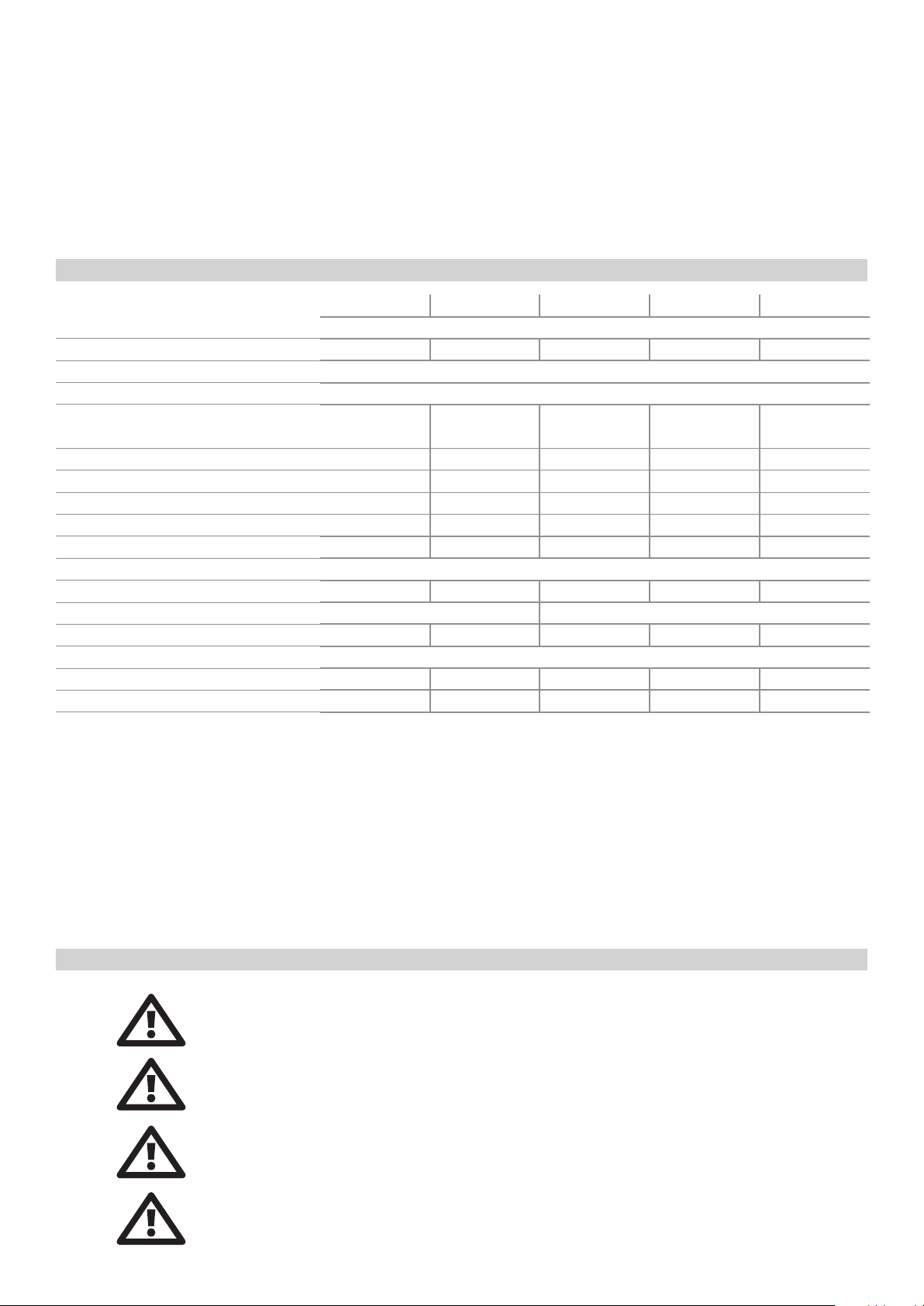
Otras causas que impidan el normal funcionamiento del aparato también pueden activar la PROTECCION.
- Cortocircuito: Estado de la línea de altavoces (posible cruce, des-
conectarlos y ver si la anomalía desaparece)
Cuando se activa alguna de las protecciones, es necesario revisar la instalación atendiendo los pasos básicos siguientes:
- Desconectar todos los aparatos periféricos conectados (fuentes,
- Si no se trata de ninguna de estas causas, consulte con un S.A.T.
autorizado.
previos y altavoces). Dejar el amplificador “solo” y verificar si la anomalía desaparece o permanece en un solo canal o en los dos.
- Temperatura: Refrigeración (posible obstrucción del aire. Ver
estado de los ventiladores –¿funcionan?-. Limpieza interna). Asegurar
En todos los casos es conveniente realizar esta primera observación
antes de solicitar Servicio Técnico e informar detalladamente sobre el
resultado obtenido.
que el equipo haya vuelto a una temperatura normal antes de volver a
poner en marcha.
15. Especificaciones
HD800 HD1200 HD2000 HD3200 HD4000
Amplificación
Sensibilidad de entrada 1 V 1.25 V 1.74 V 2 V 1.88 V
Impedancia de entrada 20 kΩ
Tiempo de subida +/-12 V/μs
Potencia de salida (1 kHz - 0,1% THD)
1
Stereo 8 Ω 230 + 230 W 350 + 350 W 600 + 600 W 1000 + 1000 W 650 + 650 W
Stereo 4 Ω 400 + 400 W 600 + 600 W 1000 + 1000 W 1750 + 1750 W 1200 + 1200 W
Stereo 2 Ω 550 + 550 W² 850 + 850 W² 1500 + 1500 W² 2500 + 2500 W² 2100 + 2100 W³
Bridge 8 Ω 800 W 1200 W 2000 W 3500 W 2840 W
Bridge 4 Ω
Consumo medio a plena potencia 4
1100 W² 1700 W² 3000 W² 5000 W² 4200 W³
3 A @ 230 V AC 4 A @ 230 V AC 5 A @ 230 V AC 6 A @ 230 V AC 7 A @ 230 V AC
Respuesta de Frecuencia 20 Hz - 20 kHz (0/-1 dB)
Factor Damping (1 kHz @ 8 Ω) 280 300 350 400 350
Diafonía 60 dB 65 dB
Relación S/N (filtro-A) 102 dB (A) 104 dB (A) 105 dB (A) 108 dB (A) 108 dB (A)
Alimentación 220 – 240 V AC- 50/60 Hz
Dimensiones (AlxAnxPr)
88 x 482 x 420 mm 88 x 482 x 420 mm 88 x 482 x 440 mm 88 x 482 x 440 mm 88 x 482 x 440 mm
Peso 14 kg 15 kg 18 kg 21 kg 21 kg
32 dB
Nota (1): Tono pulsante continuo de 20 ms (0 dB) / 480 ms (-20 dB) de acuerdo con EIA RS-490 e IEC 60268-3(IHF A-202).
Nota (2): La utilización con impedancia de 2 Ω por canal o 4 Ω bridge a máxima potencia en condiciones adversas de ventilación puede llegar a activar
las protecciones de sobretemperatura. La potencia continua a 2 Ω está limitada en tiempo por el fusible térmico rearmable (mains breaker).
Nota (3): Específicamente diseñado para la operación en bridge 4 Ω a plena potencia.
Nota (4): Consumo medio a plena potencia.
Especificaciones sujetas a cambio sin previo aviso (abril 2016).
Siguiendo las instrucciones y recomendaciones expuestas, tendremos la seguridad de que el amplificador funcionará siempre dentro de los parámetros establecidos, con lo cual queda asegurada su longevidad y total eficacia.
Certificado de Garantia (documento adjunto)
Las Condiciones y Observaciones para la aplicación del Contrato de Garantía son para todos los territorios
del Estado Español.
Para otros países, deberán observarse las particularidades de cada país, siendo el Responsable de su Aplicación el propio Delegado o Importador nacional.
Para cualquier reclamación de tipo Legal, serán únicamente válidos los Tribunales Ordinarios correspondientes a la ciudad de Terrassa (BCN-Spain).
Por favor LEA las instrucciones y condiciones recogidas en la Carta de Garantía para tener pleno.
14 User's Manual / Manual de usuario
Page 15

EXPORT DEPARTMENT – CUSTOMER SERVICE
DECLARATION OF CONFORMITY
In accordance with EN 45014:1998
Manufacturer’s Name: “AMATE AUDIO S.L.”
Manufacturer’s Address: C/ Perpinyà 25, Polígon Industrial Nord
08226 Terrassa, (Barcelona), SPAIN
Brand: “AMATE AUDIO”
We declare under our own responsibility that:
Product: Audio Power Amplifier. Audio apparatus for professional use
Name: HD800, HD1200, HD2000, HD3200, HD4000
CERTIFICATION
www.amateaudio.com
Conforms to the following product specifications:
Safety: IEC 60065-01 + A1
EMC: EN 55022:2006
EN 55103-1:2009
EN 55103-2 2009
FCC Part 15
WARNING:
In accordance to EN55022, this is a class A product. In a domestic environment this product may cause radio
interference in which case the user may be required to take adequate measures.
Supplementary Information:
The product herewith complies with the requirements of the:
Low Voltage Directive 2006/95/EC
EMC Directive 2004/108/EC
RoHS Directive 2002/95/EC
WEEE Directive 2002/96/EC
With regard to Directive 2005/32/EC and EC Regulation 1275/2008 of 17 December 2008, this product is designed,
produced, and classified as Professional Audio Equipment and thus is exempt from this Directive.
Date of issue: May 1st, 2013
Signature:
Juan Amate Lopez
General Manager
Amate Audio S.L.
Perpinyà, 25 · Polígon Industrial Nord
08226 Terrassa · Barcelona – SPAIN
T. +34 93 735 65 65
[email protected]
Conformity Marking
Page 16
HD series
High Dynamics Professional Power Amplifiers
Amplificadores profesionales de alta dinámica
The HD amplifiers have been designed, engineered
and manufactured in Barcelona – SPAIN by
Los amplificadores HD han sido diseñados y
fabricados en Barcelona – ESPAÑA por
Amate Audio S.L.
Perpinyà, 25 · Polígon Industrial Nord · 08226 Terrassa
T. +34 93 735 65 65 – F. +34 93 735 60 48 – [email protected]
R&D and FACTORY: Violinista Vellsolà, 18 · 08222 Terrassa
T. +34 93 736 23 90 – F. +34 93 786 47 00
Barcelona – SPAIN
www.amateaudio.com
© Copyright 2016 by Amate Audio S.L.
06v2016
 Loading...