


LMS206
Loudspeaker Management System
User’s manual
January 2020

LMS206 May2019
2 Amate Audio

LMS206 May2019
Safety Instructions
1. All safety instructions must be read before using this device.
2. Keep and follow these instructions
3. Heed all warnings
4. The exclamation mark in the triangle indicates internal components which if
replaced can affect safety.
5. The lightning symbol within the triangle indicates the presence of dangerous
uninsulated voltages.
6. Only clean the device with a dry cloth.
7. Do not block any ventilation openings. Install in accordance with the
manufacturer’s instructions.
8. Do not install the device near heat sources such as radiators, heaters or other
heat-emitting elements.
9. Protect the power cord from being walked on or pinched, particularly at plugs,
convenience receptacles, and the point where they exit from the apparatus
10. The equipment must be repaired by qualified technical service personnel when:
A. The mains supply cable is damaged, or
B. Any object or liquid has damaged the device; or
C. The equipment does not function normally or correctly; or
D. The equipment has been exposed to the rain; or
E. The chassis is damaged
11. Disconnect the device in the case of electric storms or during long periods of
disuse.
12. WARNING – To reduce the risk of fire or electric shock, do not expose this
device to rain or moisture
13. The equipment shall not be exposed to dripping or splashing and no objects filled
with liquids, such as vases, shall be placed on the device.
14. For hanging and installation, use manufacturer recommended accessories only.
3 Amate Audio

LMS206 May2019
1 INTRODUCTION 6
2 FEATURES 6
3 MAIN CONTROLS AND CONNECTIONS 7
3.1 THE FRONT PANEL 7
3.2 THE REAR PANEL 8
4 QUICK INSTALLATION 8
4.1 BEFORE YOU START 8
4.2 POWER UP 8
4.3 1 CONTROL SOFTWARE 9
4.4 CONNECTING THE DEVICE TO A COMPUTER 9
4.5 SYSTEM OPTIMIZATION 10
5 OPERATING THE DEVICE 12
5.1 INPUT MENUS 12
5.1.1 INPUT GAIN 12
5.1.2 DELAY 12
5.1.3 CROSSOVER 12
5.1.4 PARAMETRIC EQ 13
5.1.5 DYNAMICS COMPRESSOR 13
5.1.6 LIMITER 14
5.1.7 CHANNEL LINK 14
5.2 OUTPUT MENUS 14
5.2.1 INPUT GAIN 15
5.2.2 MIXER 15
5.2.3 DELAY 15
5.2.4 CROSSOVER 15
5.2.5 PARAMETRIC EQ 16
5.2.6 DYNAMICS COMPRESSOR 16
5.2.7 LIMITER 17
5.2.8 PHASE – PHASE INVERSION 17
5.2.9 CHANNEL LINK 17
5.3 SYSTEM MENU 18
5.3.1 LOAD - PROGRAM RECALL 18
5.3.2 SAVE - PROGRAM STORE 18
5.3.3 ACCESS LEVEL – LOCK THE FRONT PANEL THROUGH A PASSWORD 18
5.3.4 VERSION INFO 19
6 PRESETS 20
7 OPERATING THE SOFTWARE 21
7.1 DEVICE LIST 21
7.2 DEVICE OPTIONS 22
4 Amate Audio

LMS206 May2019
7.2.1 MAIN WINDOW 22
7.2.2 X-OVER WINDOW 22
7.2.3 INPUT / OUTPUT WINDOW 22
7.2.4 FILE MENU 23
7.2.5 HARDWARE MENU 23
8 QUICK REFERENCE 25
9 TROUBLESHOOTING 26
9.1 HOW TO PERFORM A FIRMWARE UPGRADE 26
9.2 PASSWORD RECOVERY 26
10 SPECIFICATIONS 27
11 ANNEX 28
5 Amate Audio

LMS206 May2019
1 INTRODUCTION
The LMS206 is a complete digital loudspeaker management system designed for the
touring or fixed sound installation markets. The absolute latest in available
technology is utilized with 64-bit floating point processors and high performance 24bit Analogue Converters. The high-bit DSP prevents noise and distortion induced by
truncation errors of the commonly used 24-bit fixed-point devices. A complete set of
parameters include I/O levels, 2 second-delay per channel, polarity, 10 bands of
parametric EQ per channel, multiple crossover selections, full function compressor
and peak limiter. Precise frequency control is achieved with its 1 Hz resolution.
Inputs and outputs can be routed in multiple configurations to meet any
requirements.
The LMS206 can be controlled or configured in real time on the front panel or with
the intuitive PC/Mac GUI accessed via the USB interface. Software upgrade for CPU
and DSP via PC keeps the device current with newly developed algorithms and
functions once available. Multiple setup storage and system security complete this
professional package.
Shipped contents:
- LMS206 unit
- AC power cord
- USB cable for PC connection
- 4x Adhesive Rubber feet
2 FEATURES
- Electronically balanced inputs
- Matched-impedance balanced outputs
- 64-bit floating point DSP
- High Performance 24-bit A/D Converters
- 1 Hz Frequency Resolution
- 10 Parametric Equalizers for each Input and Output (EQs can be set as Bell,
Notch, High Shelf, Low Shelf, Notch, Allpass, Band Pass, High Pass, Low Pass)
- Multiple Crossover types: Butterworth, Bessel, Linkwitz-Riley, up to 4th order
(24dB / oct).
- Up to 2 seconds delay per each input/output
- RMS compressor and ultra-fast attack Peak Limiter.
- Precise Level, Polarity and Delay
- 2-Line x 16 Character Blue Backlit LCD Display
- Signal LED’s on every Input and Output
- Security Lock
- USB Interface for PC/Mac Control and Configuration (on front panel)
- CPU and DSP firmware upgrade via PC/Mac interface
- 2 Inputs and 6 Outputs with flexible routing
- 110dB dynamic range (inputs) / 114dB dynamic range (outputs)
- 48kHz sampling rate
- Low latency (1.32ms)
- Storage of up to 100 Program Setups
6 Amate Audio
LMS206 May2019
<Channel:
Choose previous channel for editing.
Channel>:
Choose next channel for editing
<Select:
Select previous parameter for editing
Select>:
Select next parameter for editing
Menu:
This key has different functions depending on when it is used:
- In the Main Screen: Access the System Menu.
- In the Main Menu allows entering the System Menu.
Exit:
Exit to the Main Menu
3 MAIN CONTROLS AND CONNECTIONS
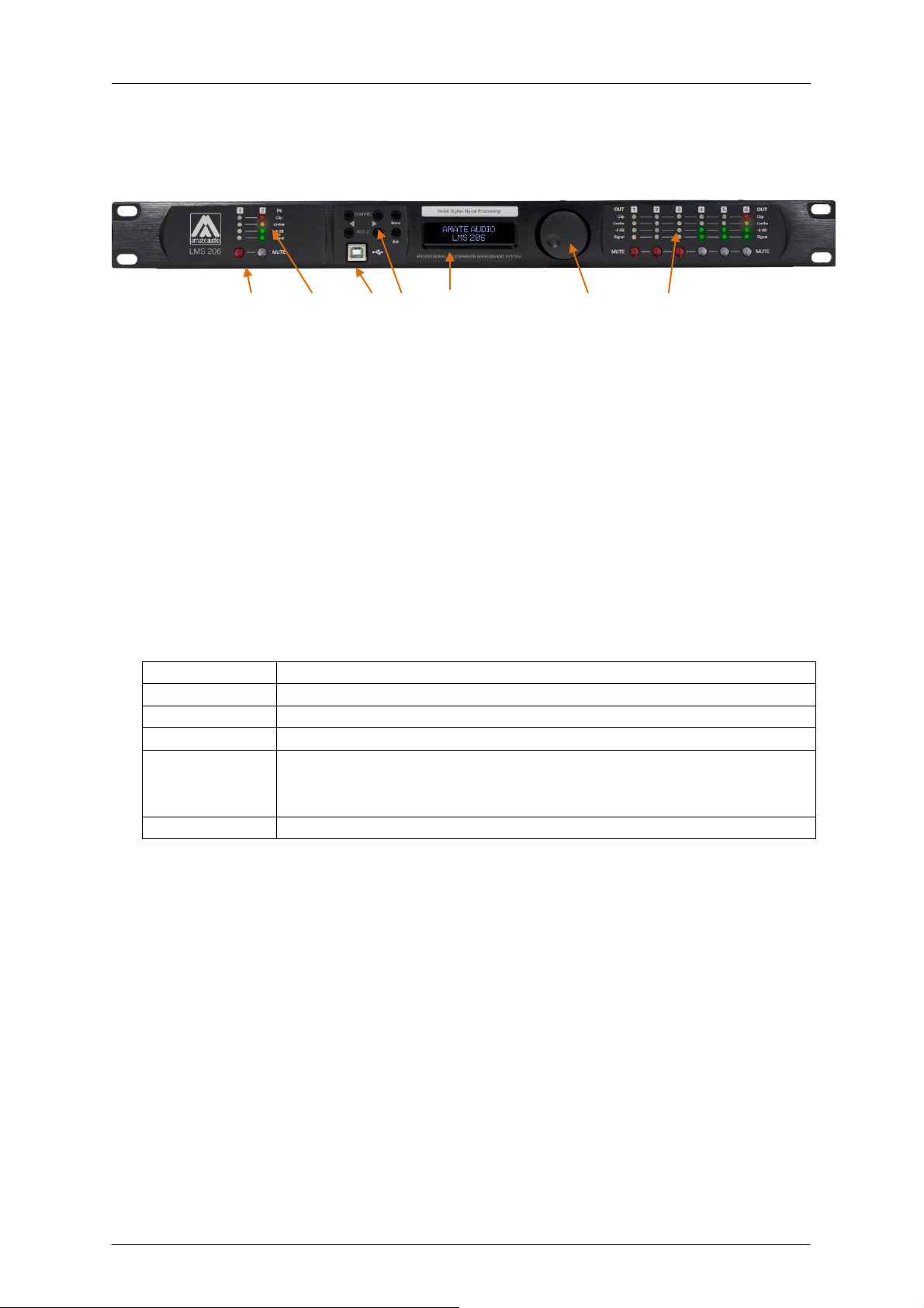
3.1 The front panel
A) Mute keys – Press for Mute/Unmute input and output channels. When a channel
is muted, this key will light up in red for indication.
B) Input signal LEDs - Show the current level of the Signal: Signal (-48dBu), -6dBu,
Limit (orange), Clip (red). The Limit led lights up if a gain reduction is taking
place (due to a programmed compressor). The Clip LED references to the
device's maximum headroom (+22dBu).
C) USB Connector – A standard type B USB connector for interface with a PC or
Mac. Software and driver must be installed prior to usage.
D) Menu Control keys - There are 6 menu keys: <Channel (Previous Channel),
Channel> (Next Channel), <Select (Previous Option), Select> (Next Option),
Menu and Exit. The functions of each key is explained below:
E) LCD - Shows all the necessary information to control the unit.
F) Rotary Thumb Wheel – Turn the wheel to change parameter data values. Click
on it to confirm the value entered. The center click of the wheel is also use to
browse different parameters of the same feature.
G) Output signal LEDs - Show the current level of the output Signal: Signal (-
48dBu), -6dBu, Limit (orange), Clip (red). The Limit led lights up if a gain
reduction is taking place (due to a programmed compressor). The Clip LED
indicates a gain this reduction is higher than 12dB.
7 Amate Audio

LMS206 May2019
Initialising...
DEFAULT PRESET
AMATE AUDIO
B
3.2 The rear panel
A) Power switch - Controls power On/Off.
B) Main Power - Connects via a standard IEC socket. A compatible power cord is
supplied with the unit. The input voltage range is 85 to 240VAC, 50-60Hz.
C) XLR input and outputs - Separate 3-pin XLR connectors are provided for each
audio input and output. The device's output stage employs the balanced
impedance topology. All I/O connectors have pin 1 as ground (shield), pin 2 as +
and pin 3 as -.
4 QUICK INSTALLATION
4.1 Before you start
Before powering up the unit, make sure that the input and output XLR cables are in
good state and following the following pinning diagram: 1 for shield, 2 for live(+), 3
for return (-) as defined by the AES14 standard.
Do not connect the unit to your computer before installing the software and the USB
Driver. Please refer to installation instructions in this manual.
When connecting the LMS206 to the amplifiers, mute the DSP outputs (or turn down
the amplifier’s volume knobs) until you configure your processing. Loudspeakers
may be damaged due to a wrong setup. It is advisable to unmute first the high
frequency channels: in case they are connected to low frequency drivers by mistake,
they cannot be damaged. Otherwise, high frequency speakers may be damaged
because of trying to reproduce low frequencies.
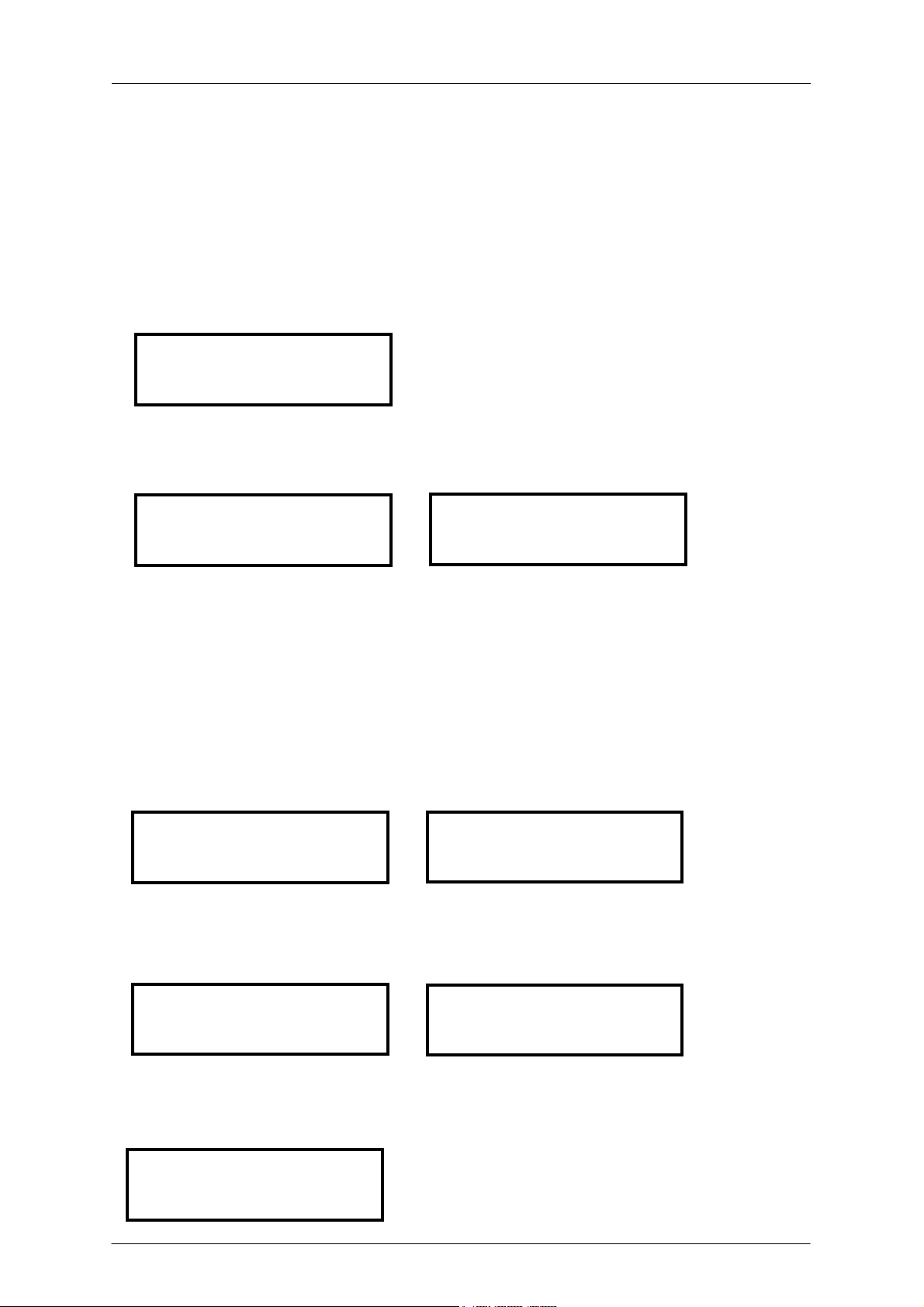
4.2 Power Up
After powering up the unit, all LEDs will be lit for about six seconds, while the
following message is displayed on the LCD:
After that, the DSP unit displays its main screen:
8 Amate Audio

LMS206 May2019
! My_Preset
AMATE AUDIO
Now the LMS206 unit is ready to operate. The screen shows the name of the unit
(above line) and the program name currently active (below line). The program
assigned is always the last program the user recalled or stored before powering
down the unit.
An admiration mark (!) beside the program name means that the program has been
modified but not stored. This symbol does not appear when the modified program is
the default preset.
4.3 1 Control Software
The LMS206 units can be controlled via a Computer Software which provides a
Graphic User Interface (GUI) application - DSPLink. DSPLink allows the user to
control the DSP unit from a computer via the USB communication link. For the USB
connection, a driver must be installed (included with the DSPLink installation
package).
The GUI application makes it much easier to control and monitor the device, allowing
the user to get the whole picture on one screen. Programs can be recalled and
stored from/to Computer’s hard drive, thus expanding the storage to become virtually
limitless. See Section 6 of this manual for instructions to operate the software.
DSPLink is available for PC and Mac. Check Amate Audio’s website for a latest
version download (www.amateaudio.com).
Installation for PC-Windows:
Double click the installation file, depending whether you have a 32 or a 64-bit
system:
Amate_Audio_DSPLink_32_bit_v_10_X_X_BuildNr.msi
Amate_Audio_DSPLink_64_bit_v_10_X_X_BuildNr.msi
Follow the on-screen instructions. You may be prompted to install the Microsoft
Visual Runtime libraries before finishing the installation. Click the checkbox to
proceed with this action.
Installation for Mac:
First unzip the provided installation file:
Amate_Audio_DSPLink_v_10_X_X_BuildNr.mpkg.zip
Then select the .mkpg file with CONTROL+Click and select “Open”. Then follow the
on-screen instructions.
4.4 Connecting the device to a computer
WARNING: Always install the software package DSPLink before connecting your
unit to the computer. See previous section for details.
After installing DSPLink, please use the provided USB cable to connect the unit to
your computer. The first time you connect a device, the system will ask you to look
9 Amate Audio

LMS206 May2019
for the driver. Choose the option “do not look for updates and to automatically select
the best driver”.
Run DSPLink and the unit will be automatically detected. Click on the arrow next to
the detected unit to open the window for parameter edition.
4.5 System Optimization
In order to have a proper start of your system and an optimized configuration, follow
these steps by the first configuration:
1. Play a signal at the nominal level from your mixing desk, and set the input
gain of your processor to 0dB (Default Preset setting)
2. Set the crossovers that you want to use, while keeping the output gains also
at 0dB.
3. With DISCONNECTED loudspeakers, turn up the volume of the power
amplifiers entirely clockwise (full volume).
4. Reduce the output gain and / or the output limiter setting to get the desired
gain, so that the amplifier is just clipping and the built-in limiters of your
processor are just limiting (Orange led blinking at the output channels).
5. Turn down the volume of the power amplifiers, connect your speakers, and
slowly increase the volume while checking the sound.
6. Check if the loudspeakers are reproducing distortion-free sound, and the
limiter LEDs are flashing or off, but not continuously on. If they are
continuously on, reduce the output gain of your processor.
7. If you cannot reach enough signal level, increase the processor's input gain or
turn up the level from your mixing desk
10 Amate Audio

LMS206 May2019
4.6 Diagram of a typical setup
With illustrative purposes, a diagram of a LMS206 working as audio manager in a
typical setup is shown above. The audio processor is used for splitting the stereo
signal coming from a mixer in two zones for different public. In fixed setups, is
common that these two zones have different acoustical properties so different audio
gear is expected. Due the previous considerations, a different signal processing for
each zone is expected.
11 Amate Audio

LMS206 May2019
-1.25dB
In 12 Gain
0.090ms
In 12 Delay
Freq: 15000Hz
In 12 LowPass
Type: BUT 24dB
In 12 LowPass
Type: BUT 24dB
In 12 HighPass
Freq: 40Hz
In 12 HighPass
5 OPERATING THE DEVICE
5.1 Input Menus
To access the Input Menus press the <Channel or Channel> key. Press Exit to finish
editing or again <Channel or Channel> to edit other channels.
The following menus are available for each input channel. Please note that by
default the inputs and outputs channels are linked in groups of two. The following
options are shown for the input group composed of In1 and In2
5.1.1 Input Gain
Adjust the gain of each input, using the rotary knob.
5.1.2 Delay
Adjust the delay by turning the rotary knob. Push this knob to switch the unit
between ms, ft or m.
5.1.3 Crossover
• Low Pass – First adjust the Low Pass Filter cut-off frequency. To switch it off, turn
the rotary knob clockwise until “Off” is displayed.
Second, press the rotary knob and select from the available types and slopes:
Type: Butterworth, Slopes: 6dB, 12dB, 18dB or 24dB
Type: Bessel. Slopes: 6dB, 12dB, 18dB or 24dB
Type: Linkwitz-Riley. Slope: 12dB or 24dB
• High Pass – First adjust the High Pass Filter cut-off frequency. To switch it off, turn
the rotary knob counter-clockwise until “Off” is displayed.
Second, press the rotary knob and select from the available types and slopes:
Type: Butterworth, Slopes: 6dB, 12dB, 18dB or 24dB
Type: Bessel. Slopes: 6dB, 12dB, 18dB or 24dB
Type: Linkwitz-Riley. Slope: 12dB or 24dB
12 Amate Audio

LMS206 May2019
Q: 2.36
In 12 PEQ 1
Enabled: On
In 12 PEQ 1
Thr.: 24.00dBu
In 12 Compr.:
Att.: 20ms
In 12 Compr.:
Type: Bell
In 12 PEQ 1
Freq: 1000Hz
In 12 PEQ 1
Gain: 0.00dB
In 12 PEQ 1
5.1.4 Parametric EQ
Select between one of the 10 available Equalizers on each input channel by using
the keys < Select and Select >. Browse the parameters by turning the rotary knob
and push the knob to select and confirm the values. The following parameters can
be adjusted for each EQ:
• Freq - EQ center frequency.
• Gain - EQ level gain.
• Q - EQ Bandwidth. For shelving filters the Q sets the transition in dB/Oct. See
Annex1 for further information about the Q factor implementation in the LMS206.
• Type - Shape of EQ. The available types are:
Bell: Modifies the gain of a certain frequency range, with bell shape
Notch: Eliminates a range around a center frequency
Low-Shelf: Modifies the gain of all the range below a selected frequency.
High-Shelf: Modifies the gain of all the range above a selected frequency.
All Pass: Modifies the phase response, without influencing the frequency response.
Band Pass: Filters out all the range except the defined band.
High Pass: Filters out all the range below a certain frequency.
Low Pass: Filters out all the range above a certain frequency.
• Enabled – When set On, the currently selected EQ is on line.
5.1.5 Dynamics Compressor
A true RMS compressor can be set to avoid the input signal go above a certain RMS
value. The following parameters can be adjusted:
• Thr. - Compressor Threshold. Sets the level at which the compressor will activate.
• Att. - Attack time. Time it takes the compressor to start actuating after reaching the
threshold.
• Hold - Hold time. Sets up a delay before the compressor enters the release cycle.
Useful for compressing low frequency long notes.
13 Amate Audio

LMS206 May2019
Thr.: 24.00dBu
In 12 Limiter
Hold: 10ms
In 12 Compr.:
Ratio: 5.00:1
In 12 Compr.:
Rel.: 200ms
In 12 Compr.:
Gain: 1.00dB
In 12 Compr.:
Rel.: 50
In 12 Limiter
On
In 12 Link:
• Rel. - Release time. Time the compressor uses to return to unity gain after the
signal is below the threshold.
• Ratio - The compressor ratio determines the slope in which the signal is
compressed. The higher this value is, the higher the compression.
• Gain – The compressor make up Gain. Use it in case the level of the compressed
signal must be corrected (0dB by default)
5.1.6 Limiter
A peak-limiter can be set at each input. It is a zero attack time limiter, so it will
immediately act on the signal. The parameters that can be changed are:
• Thr. – Threshold: input level at which the signal will be limited.
• Rel. – The release value, expressed in dB/seconds
5.1.7 Channel Link
Input channels 1 and 2 can be linked in order to set the same parameters on both.
The factory setting is that channel 1 and 2 are linked. Turn the rotary knob set the
link off.
5.2 Output Menus
To access the Input Menus press the <Channel or Channel> key. Press Exit to finish
editing or again <Channel or Channel> to edit other channels.
The following menus are available for each output channel. Please note that by
default the inputs and outputs channels are linked in groups of two. The following
options are shown for the output group composed of Out1 and Out2.
14 Amate Audio

LMS206 May2019
0.50dB
Out12 Gain
0.000ms
Out12 Delay
Freq: 1500Hz
Out12 LowPass
Type: BUT 24dB
Out12 LowPass
Type: BUT 24dB
Out12 HighPass
Freq: 40Hz
Out12 HighPass
Input 1 0.00dB
Out1 Mixer
Input 2 Off
Out1 Mixer
5.2.1 Input Gain
Adjust the gain of each output, using the rotary knob.
5.2.2 Mixer
Select the level to be routed from each input by turning the rotary knob. Select 0dB
for maximum level of an input. To disable one input, turn the rotary knob counterclockwise until “Off” is displayed. Push the rotary knob to select the next input.
5.2.3 Delay
Adjust the delay by turning the rotary knob. Push this knob to switch the unit
between ms, ft or m.
5.2.4 Crossover
• Low Pass – First adjust the Low Pass Filter cut-off frequency. To switch it off, turn
the rotary knob clockwise until until “Off” is displayed.
Second, press the rotary knob and select from the available types and slopes:
Type: Butterworth, Slopes: 6dB, 12dB, 18dB or 24dB
Type: Bessel. Slopes: 6dB, 12dB, 18dB or 24dB
Type: Linkwitz-Riley. Slope: 12dB or 24dB
• High Pass – First adjust the High Pass Filter cut-off frequency. To switch it off, turn
the rotary knob counter-clockwise until “Off” is displayed.
Second, press the rotary knob and select from the available types and slopes:
Type: Butterworth, Slopes: 6dB, 12dB, 18dB or 24dB
Type: Bessel. Slopes: 6dB, 12dB, 18dB or 24dB
Type: Linkwitz-Riley. Slope: 12dB or 24dB
15 Amate Audio

LMS206 May2019
Q: 2.36
Out12 PEQ 1
Enabled: On
Out12 PEQ 1
Thr.: 24.00dBu
Out12 Compr.
Att.: 20ms
Out12 Compr.
Type: Bell
Out12 PEQ 1
Freq: 1000Hz
Out12 PEQ 1
Gain: 0.00dB
Out12 PEQ 1
5.2.5 Parametric EQ
Select between one of the 10 available Equalizers on each output channel by using
the keys < Select and Select >. Browse the parameters by turning the rotary knob
and push the knob to select and confirm the values. The following parameters can
be adjusted for each EQ:
• Freq - EQ center frequency.
• Gain - EQ level gain.
• Q - EQ Bandwidth. For shelving filters the Q sets the transition in dB/Oct. See
Annex1 for further information about the Q factor implementation in the LMS206.
• Type - Shape of EQ. The available types are:
Bell: Modifies the gain of a certain frequency range, with bell shape
Notch: Eliminates a range around a center frequency
Low-Shelf: Modifies the gain of all the range below a selected frequency.
High-Shelf: Modifies the gain of all the range above a selected frequency.
All Pass: Modifies the phase response, without influencing the frequency response.
Band Pass: Filters out all the range except the defined band.
High Pass: Filters out all the range below a certain frequency.
Low Pass: Filters out all the range above a certain frequency.
• Enabled – When set On, the currently selected EQ is on line.
5.2.6 Dynamics Compressor
A true RMS compressor can be set to avoid the output signal go above a certain
RMS value. The following parameters can be adjusted:
• Thr. - Compressor Threshold. Sets the level at which the compressor will activate.
• Att. - Attack time. Time it takes the compressor to start actuating after reaching the
threshold.
16 Amate Audio

LMS206 May2019
Thr: 12.00dBu
Out12 Limiter
Hold: 10ms
Out12 Compr.
Ratio: 5.0:1
Out12 Compr.
Rel.: 200ms
Out12 Compr.
Gain: 3.0dB
Out12 Compr.
Rel: 50dB
Out12 Limiter
On
Out12 Link:
Normal
Out12 Phase:
• Hold - Hold time. Sets up a delay before the compressor enters the release cycle.
Useful for compressing low frequency long notes.
• Rel. - Release time. Time the compressor uses to return to unity gain after the
signal is below the threshold.
• Ratio - The compressor ratio determines the slope in which the signal is
compressed. The higher this value is, the higher the compression.
• Gain – The compressor make up Gain. Use it in case the level of the compressed
signal must be corrected (0dB by default)
5.2.7 Limiter
A peak-limiter can be set at each output. It is a zero attack time limiter, so it will
immediately act on the signal. The parameters that can be changed are:
• Thr. – Threshold: input level at which the signal will be limited.
• Rel. – The release value, expressed in dB/seconds
For Amate Audio passive cabinets, there is a tool that easily computes the correct
value of the limiter threshold for each output. These values are the result of a deep
study made in out R+D facilities, thus its use guarantee protection without
compromising the performance of the system. This tool is available at
www.amateaudio.com/en/LimCal.
5.2.8 Phase – Phase inversion
Change the polarity of the channel by a 180º phase inversion. Select between
Normal or Inverted.
5.2.9 Channel Link
Output channels can be linked in order to set the same parameters on both. The
factory setting is that output channels 1&2, 3&4, 5&6 are linked. Turn the rotary knob
set the link off.
17 Amate Audio
LMS206 May2019
My_Preset
Load: 1
no/YES
Save Preset?
Empty
Save: 4
Unlocked
Access Level:
NO/yes
Load Preset ?
no/YES
Load Preset ?
My_Pre_
Set Presetname:
My_Preset
Preset Saved OK
5.3 System Menu
The System Menu allows the user to control and change parameters that are related
to the system behaviour and general operation. It can be accessed by pressing the
Menu key on the front panel. The available options are:
5.3.1 Load - Program Recall
The LMS206 unit has a built-in non-volatile memory that can store different program
setups. A program can be recalled using this menu. Use the rotary knob to browse
the desired program to load and click it to accept
Confirm your selection by turning the rotary knob until “YES” is in capital letters and
press enter again.
5.3.2 Save - Program Store
A program can be stored using this menu. The old program with the same program
number will be replaced. Once the program is stored in the flash memory, it can be
recalled at a later time, even after power down.
Select the number of slot where the current setting will be stored by rotating the
thumbwheel and pressing it to confirm. After that, it is required to enter a name for
the new preset, using the rotary wheel to select the characters and the center click to
confirm:
Once you finish typing the name of the preset, press again the Menu key to confirm.
Press the rotary knob to select “YES”. A confirmation message is displayed.
5.3.3 Access Level – Lock the front panel through a password
18 Amate Audio

LMS206 May2019
**** Locked ****
Access Level:
MyPass
Set Password:
MyPass
Confirm Password
Access Level:
Unlocked
Access Level:
Pas_
Enter Password
SN: 0000010262
Version Info
SW:10.0.3.105796
Version Info
HW: 4.9.3
Version Info
To lock the system, turn the rotary knob until the word “Locked” is displayed. The
system will prompt for a password.
The password may be up to 8 characters long. When entering shorter passwords,
use the Menu key to finish and confirm. Use the Exit key to go back and make the
password shorter.
WARNING: If blank spaces are included in the password, they will be stored and
must be entered in the same position in order to unlock the device.
NOTE: The factory default password is “Password”
After that the system will be LOCKED and only the Mute buttons and the Menu key
will be active.
To UNLOCK the device, proceed with the following steps:
Press the menu key. The Lock screen will appear. Turn the rotary knob
counterclockwise to select “Unlocked”
Then enter the password. Click enter to finish.
5.3.4 Version Info
Shows the device software and hardware information. Turn the rotary knob to display
the information available:
19 Amate Audio

LMS206 May2019
Nº
Tipo
Nombre
OUT1 a OUT4
OUT 5 & 6
1
Read-Only
N6P
N6P / FLAT
N6P / FLAT
2
Read-Only
N6P & N12WP
N6P / XOVER
N12WP / LPF90+3
3
Read-Only
N26P
N26P / FLAT
N26P / FLAT
4
Read-Only
N26P & N12WP
N26P / XOVER
N12WP / LPF90+3
5
Read-Only
N12P
N12P/ FLAT
N12P/ FLAT
6
Read-Only
N12P & N18WP
N12P / XOVER
N18WP / LPF90+3
7
Read-Only
N12PR
N12PR / FLAT
N12PR / FLAT
8
Read-Only
N12PR & N18WPR
N12PR / XOVER
N18WPR/LPF90+3
9
Read-Only
N15P
N15P / FLAT
N15P / FLAT
10
Read-Only
N15P & N18WP
N15P / XOVER
N18WP / LPF90+3
11
Read-Only
N15P & N218WP
N15P / XOVER
N218WP/LPF90+3
12
Read-Only
N15PR
N15PR / FLAT
N15PR / FLAT
13
Read-Only
N15PR & N18WPR
N15PR / XOVER
N18WPR/LPF90+3
14
Read-Only
KEY10
KEY10 / FLAT
KEY10 / FLAT
15
Read-Only
KEY10 & N12WP
KEY10 / XOVER
N12WP / LPF90+3
16
Read-Only
KEY10 & N18WP
KEY10 / XOVER
N18WP / LPF90+3
17
Read-Only
KEY12
KEY12 / FLAT
KEY12 / FLAT
18
Read-Only
KEY12 & N18WP
KEY12 / XOVER
N18WP/ LPF90+3
6 PRESETS
The LMS206 is shipped with several presets pre-loaded in the unit that help in the
set-up of the sound system. These presets have been designed and selected for
deliver an active loudspeaker response (with internal amplification) when using them
with our passive cabinets, as well for positive interfering in low frequency range and
for protecting the sound system in over-voltage case.
In the following diagram, the list of the presets is displayed:
In the case of set-ups without subwoofer units, the presets configure the passive
loudspeakers as full-range loudspeakers so they will reproduce all the frequency
range.
For the case of set-ups with subwoofers, the output channels from 1 to 4
(Corresponding to the “tops”) are configured with a high pass filter, and the channels
5 to 6 (Corresponding to the “subs”) are configured with a low pass filter and a boost
of 3 dB in the tuning frequency. In this way we obtain a set-up with a balanced
frequency response.
These presets are read-only, in consequence they can’t be overwritten, edited nor
deleted. If you want to edit a preset, before is necessary to copy it to another free
memory available.
The presets don’t include the proper limiter threshold, since it depends in the number
of cabinets and amplifier type that are part of the sound system. For computing the
proper limiter threshold, it is highly recommended to use the tool we have available
in the following link: amateaudio.com/en/LimCal
20 Amate Audio

LMS206 May2019
7 OPERATING THE SOFTWARE
7.1 Device List
Once the software DSPLink is started, a window with the list of connected devices is
shown. The main controls are as following:
MUTE: The device will be completely muted when this button is clicked. Click it
again to unmute.
IDENTIFY: When pressing this button, the device will blink 5 times its leds on the
front panel. Useful for installations with several DSP connected to the computer, in
order to identify each unit.
STANDBY: When this button is clicked, the DSP will go into standby mode (low
power consumption). In this mode, there is no output signal. Click the button again to
recover the normal operation mode.
EDIT: Open control window for full control of the device.
The following options are available in this window:
File / Quit: Close the program.
Tools
o Change software password: allows the user to create a password to
access the software. By default, no passwrod is needed. If a password
is set and then forgotten, the software must be reinstalled.
o New Group: create a group that associates 2 or more DSP.
o Enter Demo Mode: enables to use the software without a connected
device.
o Enable Update: Enables the firmware upgrade of the units in the list
(an Administrator password is required, see Section 8).
Help
o Request Support: sends a report about a problem in the software,
o About: Shows basic info about the application
21 Amate Audio

LMS206 May2019
7.2 Device Options
7.2.1 Main window
In this window the Preset options, the device name, and the input and output levels
and VUMeters, as well as the link and mute settings are displayed.
7.2.2 X-over window
In this window all the crossover settings for each output are displayed and can be
set. The same information can be found on each channel’s window.
7.2.3 Input / Output window
When selecting one of the inputs or outputs on the left side, a window with all
available controls will be displayed: Mixer, PEQ, Xover, Gain, Mute, Polarity, Limiter
and Compressor.
To access all available parameters of the Compressor, click on the word
“COMPRESSOR” besides the Limiter control. A new window will display showing the
controls for Threshold, Attack, Hold, Release, Ratio and Makeup Gain.
22 Amate Audio

LMS206 May2019
7.2.4 File Menu
Open: Load a preset from a previously stored file.
Save: Save current preset to a file in the hard disk.
Restore Presets: Load a set of presets from a previously stored file.
Backup Presets: Backup all the presets of the device to the hard disk.
Quit: Exit the device’s main window.
7.2.5 Hardware Menu
Enter Password: Enter a password here to unlock the unit (only needed if the
unit has been previously locked using the option “Hardware>Lock Unit”).
Configure:
o Change password: change the factory default password. The new
password may have up to 8 characters. You will be first asked for the
23 Amate Audio

LMS206 May2019
old password. NOTE: The factory default password is “Password”
(case sensitive)
o Power On Preset: Set here the preset that will be selected at startup.
The default setting is “last setting”.
o Global Access Rights: select which controls will be unlocked even the
“Lock Unit” control is selected. Click on the checkbox of the functions
that should be available to the user without entering a password:
o Output mode: pre-select the input assignment to outputs, in groups of
two (Dual Bridge or Mono).
Lock unit: In order to lock the unit by password, select “Hardware > Lock
Unit”. To unlock the unit again, select “Hardware > Enter Password”.
Set Pin: Set a 4-digit pin to allow the access to the unit via software. If the
PIN needs to be removed, select this function and leave the PIN field blank
(the message “Invalid PIN” will be shown). If the PIN is forgotten, a firmware
upgrade is needed (see Chapter 9).
Status Details: A quick information window about the device is displayed.
24 Amate Audio

LMS206 May2019
Menu
Function
Channel
Parame
ter
Value
Units
Gain
I / O
Gain
-48 to +12; Step: 0.25
dB
Mixer
Outputs
Input
1/2/3/4
-48 to 0; Step: 0.25
dB
Delay
I / O
Delay
0 to 2000; Step depends on range
ms
LowPass /
High Pass
I / O
Freq.
20 to 20000; Step depends on range
Hz
Type
BUT 6dB / BES 6dB / BUT12 dB / BES
12 dB / LR 12 dB / BUT 18 dB / BES
18dB / BUT 24dB / BES24 dB / LR 24dB
Enabled
On / Off
PEQ 1 to
PEQ 10
I / O
Freq.
20 to 20000; Step depends on range
Hz
Gain
-12 to 12; Step: 0.25
dB Q 0.2 to 25; Step: 0.1
Type
Bell / Notch / High Shelf / Low Shelf /
Allpass/ Band Pass/ High Pass/ Low
Pass
Enabled
On / Off
Compressor
I / O
Thr.
-48 to +24; Step: 0.25
dBu
Att.
1 to 10000; Step: 1
ms
Hold
1 to 10000; Step: 1
ms
Release
1 to 10000; Step: 1
ms
Ratio
1.2:1 to 25:1
Makeup
Gain
-12 to +12; Step: 0.25
dB
Limiter
Input
Thr.
-48 to +24; Step: 0.25
dBu
Rel.
10 to 100; Step: 1
dB/s
Limiter
Output
Thr.
-48 to +12; Step: 0.25
dBu
Rel.
10 to 100; Step: 1
dB/s
Phase
Output
Phase
Normal / Inverted
Link
I / O
Link
Off / On
8 QUICK REFERENCE
25 Amate Audio

LMS206 May2019
9 TROUBLESHOOTING
9.1 How to perform a firmware upgrade
To perform a firmware upgrade, proceed as following:
WARNING: In the Firmware Upgrade Process all your presets will be erased. Please
make a backup of them before upgrading the unit. During the upgrade process you
will be asked to perform this backup.
1. Connect the unit to the computer
2. Using DSPLink, enter the Device Main Window
3. Choose “Hardware > Enter Password”
4. Enter the administrator password, which is “Ad_min”
5. Go to “Hardware > Firmware Upgrade”
6. Be careful to answer “Yes” if you want your settings and presets to be backed
up
7. Wait until firmware is upgraded. Do not plug off or disconnect the unit from the
computer during this process.
8. Your presets will be restored automatically
9.2 Password recovery
The unit is shipped unlocked, so no password will be necessary unless the unit is
locked by the user. The default user password is “Password”.
In case this Password has been changed by the user (Using the Menu “Hardware >
Configure > Change Password”) and is no longer remembered, a Firmware Upgrade
is needed to re-establish the password to the default value (see previous section).
26 Amate Audio

LMS206 May2019
DSP206
Analog Inputs
Number
2
Input Impedance
>10 kOhms
Maximum Level
+23 dBu
Type
Electronically balanced
Analog Outputs
Number
6
Maximum Level
+12 dBu
Type
Impedance Matched
Audio Performance
Frequency Response
20Hz to 20kHz (+/- 0.5dB)
Input Dynamic Range
110 dB (unweighted)
Crosstalk
< -80 dB
Distortion
0.005% (A-weighted)
Digital Audio Performance
Processing
64-bit
Analog Converters
High Performance 24-bit
Sampling Rate
48 kHz
Propagation Delay
1.32 ms
Front Panel Controls
Display
2 x 16 Character. White Backlit LCD
Level Meters
Per I/O: Signal Present, -6dB; Limiter, Clip
Buttons
Illuminated Mute Controls, Menu Controls
Dial Encoder
Rotary Thumb Wheel
Connectors
Analog Audio
3-pin XLR Pin 1: shield 2: live (+) 3: return (-)
USB
Type B (on front panel)
Power
Standard IEC Socket
General
Power
85 to 240 VAC (50 / 60 Hz)
Dimensions (H x W x D)
1U 19” Rack 44 x 483 x 165 mm
Weight
2.3kg
System Parameters
No. of Programs
100
Program Names
16 character length
Security Lock
Password Lock/Unlock
10 SPECIFICATIONS
Note: Specifications subject to change without notice
27 Amate Audio

LMS206 May2019
11 ANNEX
1
For bell parametric filters (PEQ), the bandwidth definition differs among the
different DSP manufacturers. For this reason, it is difficult to successfully copy filter
settings between different processors.
The frequency span of the filter is defined by either the bandwidth or the Q factor.
These parameters are inversely proportional, meaning the bigger the bandwidth, the
smaller the Q. The formulas relating both parameters are:
The border frequencies of the bandwidth are usually set at the point where the
energy decreases three decibels, as shown in Figure 1.
Fig. 1: Bandwidth graphical representation
The majority of audio processor manufacturers implement the Q in four different
ways: Bandpass-Q, Constant-Q, dB/2 and 3dB hybrid method. The first two are
based in analogue filters, while the last two take advantage of the capabilities of
digital processing.
The Bandpass-Q method builds the bell filter adding the response of a band-pass
filter plus a gain block to the input signal, as shown in Figure 2.
28 Amate Audio

LMS206 May2019
Bandpass filter
Adding block
Filter gain
Input signal
INPUT
OUTPUT
Fig. 2: Block diagram of a bell filter
As shown in Fig. 2, when adding both processed and original signals at the output,
the bandwidth of the resulting signal is higher than the bandwidth of the bandpass
filter used. The Bandpass-Q method defines the Q of the bandpass filter block, and
not of the resulting filter. The difference is shown in Figure 3.
Fig. 3. Red line: Bandpass filter with 6dB gain. Dotted blue line: Parametric bell filter.
To avoid this difference, Constant-Q implementations lower the Q that the user
selects in the bandpass filter, just enough to compensate this difference. In
consequence, the resulting Q at the output is the same as the user expects.
However, this solution cannot be applied for filters with a peak gain lower than 3dB.
The dB/2 method always sets the bandwidth as one-half of the peak gain, so the
definition works no matter what the peak gain is. Amate Audio LMS206 uses the
dB/2 method, because it keeps the bell shape independent from the peak gain.
The 3dB Hybrid Method works in two ways: If the peak gain is greater than 6dB, the
bandwidth is set at -3dB of the peak (Constant-Q), otherwise it uses the dB/2
definition, setting the bandwidth to one-half of the peak gain.
29 Amate Audio

Conformity
Marking
DECLARATION OF CONFORMITY
In accordance with EN 45014:1998
Manufacturer’s Name: “AMATE AUDIO S.L.”
Manufacturer’s Address: C/ Perpinyà 25, Polígon Industrial Nord
08226 Terrassa, (Barcelona), SPAIN
Brand:
“AMATE AUDIO”
We declare under our own responsibility that:
Product:
Name: LMS206
Conforms to the following product specifications:
Safety: IEC 60065-01 + A1
EMC: EN 55022:2006
EN 55103-1:2009
EN 55103-2 2009
FCC Part 15
WARNING:
In accordance to EN55022, this is a class A product. In a domestic environment this product may cause radio
interference in which case the user may be required to take adequate measures.
Supplementary Information:
The product herewith complies with the requirements of the:
Low Voltage Directive 2006/95/EC
EMC Directive 2004/108/EC
RoHS Directive 2002/95/EC
WEEE Directive 2002/96/EC
With regard to Directive 2005/32/EC and EC Regulation 1275/2008 of 17 December 2008, this product is
designed, produced, and classified as Professional Audio Equipment and thus is exempt from this Directive.
Date of issue:
Signature:
Juan Amate Lopez
General Manager
Audio signal processor. Audio apparatus for professional use
April 30th, 2019


LMS digital signal processors have been designed,
engineered and manufactured in Barcelona – SPAIN
by
Amate Audio S.L.
Perpinyà, 25 · Polígon Industrial Nord · 08226 Terrassa
T. +34 93 735 65 65 – F. +34 93 735 60 48 –
Violinista Vellsolà, 18 · 08222 Terrassa
info@amateaudio.com
R&D and FACTORY:
Barcelona – SPAIN
www.amateaudio.com
© Copyright 2019 by Amate Audio S.L.
 Loading...