

Page 1
INSTALLATION AND OPERATION INSTRUCTIONS FOR
INSTALLER: LEAVE OWNER’S MANUAL WITH THE APPLIANCE.
CONSUMER: RETAIN OWNER’S MANUAL FOR FUTURE REFERENCE.
SAFETY INFORMATION
WARNING
For your safety, always comply with all
warnings and safety instructions
contained in this manual to prevent
personal injury or property damage.
Do not store or use gasoline or other flammable vapors
and liquids in the vicinity of this appliance.
TRD-26
TRD-30
TRD-33
TRD-38
TRD-44
TRD-48
Page 2

2
Please read and carefully follow all of the instruction found in this manual. Please pay special
attention to the safety instructions provided in this manual. The instructions included here will
assure that you have many years of dependable and enjoyable service from your Amantii product.
Table of Contents
IMPORTANT INSTRUCTIONS ............................................................................................................................. 3
PLUG INSTALLATION .......................................................................................................................................... 6
UNPACKING AND TESTING APPLIANCE ........................................................................................................ 7
LOCATING THE FIREPLACE ............................................................................................................................... 7
TRD-26 ..................................................................................................................................................................... 8
TRD-30 ..................................................................................................................................................................... 9
TRD-33 ................................................................................................................................................................... 10
TRD-38 ................................................................................................................................................................... 11
TRD-44 ................................................................................................................................................................... 12
TRD-48 ................................................................................................................................................................... 13
INSTALLATION BUILT-IN ................................................................................................................................. 14
MEDIA OPTIONS ................................................................................................................................................. 18
OPERATION ......................................................................................................................................................... 19
MANUAL OPERATION ....................................................................................................................................... 19
REMOTE CONTROL OPERATION .................................................................................................................... 20
CARE AND MAINTENANCE .............................................................................................................................. 23
REPLACEMENT PARTS ...................................................................................................................................... 24
EXPLODED VIEW ................................................................................................................................................ 26
TROUBLE SHOOTING......................................................................................................................................... 2 7
SERVICE HISTORY ............................................................................................................................................. 28
WARRANTY ......................................................................................................................................................... 29
Page 3

3
IMPORTANT INSTRUCTIONS
Please read the following instructions carefully before using the appliance.
Caution -
Fire, electric shock, physical injury and material damage hazards:
To use the appliance, always follow the instructions for assembly, use and maintenance as well as
usage cautions:
1. Carefully read and retain these instructions.
2. Before connecting the appliance, be sure that the mains voltage available matches that specified
on the rating plate.
3. Do not use the appliance for other than its intended use. For domestic indoor use only.
4. There may be trace of odour during the first few minutes of initial use. This is normal and will
quickly disappear.
5. The heater is hot when in use. To avoid burns, do not let bare skin touch any hot surface.
6. Keep combustible material such as furniture, cushions, bedding, paper, clothes, curtains etc. at
least 1m away from the heater.
7. Do not use the heater in areas where flammable liquids are stored or where flammable fumes
may be present.
8. Do not cover or obstruct any of the heat outlet grilles or the air intake openings of the heater.
9. Do not use the heater in the rooms with explosive gas or while using inflammable solvents,
varnish or glue.
10. Keep the heater clean. Do not allow any objects to enter any ventilation or exhaust opening as
this may cause electric shock, or fire or damage to the heater.
11. Always unplug or disconnect the appliance from the mains power supply when not in use or
when moving or cleaning it. Do not pull the cord to unplug the heater.
12. Do not immerse the cord, plug or any part of the appliance in water or any other liquid.
13. Do not attempt to repair, disassemble or modify the appliance. There are no user-serviceable
parts inside.
14. The heater must not be located immediately below a socket-outlet.
15. Do not use this heater in the immediate surroundings of a bath, a shower or a swimming pool.
16. CAUTION: In order to avoid a hazard due to inadvertent resetting of the thermal cutout, this
appliance must not be supplied through an external switching device, such as a timer, or
connected to a circuit that is regularly switched on and off by the utility.
17. Do not use this heater with a programmer, timer, separate remote-control system or any other
device that switches the heater on automatically, since a fire risk exists if the heater is covered or
positioned incorrectly.
18. WARNING: In order to avoid overheating, do not cover the heater.
19. WARNING! – DO NOT COVER THIS APPLIANCE WITH ITEMS SUCH AS CLOTHING, BLANKETS OR
PLACE NEXT TO CURTAINS OR NET/BLINDS.
20. If the supply cord is damaged, it must be replaced by the manufacturer, its service agent or
similarly qualified persons in order to avoid a hazard.
21. Do not use this heater in small rooms when they are occupied by persons not capable of leaving
Page 4

the room on their own, unless constant supervision is provided.
22. If the glass is damaged, do not use the heater in order to avoid a hazard.
23. Children of less than 3 years should be kept away from unless continuously supervised.
24. Children aged from 3 years and less than 8 years shall only switch on/off the appliance provided
that it has been placed or installed in its intended normal operating position and they have been
given supervision or instruction concerning use of the appliance in a safe way and understand the
hazards involved, Children aged from 3 years and less than 8 years shall not plug in, regulate and
clean the appliance or perform user maintenance.
25. CAUTION Some parts of this product can become very hot and cause burns. Particular attention
has to be given where children and vulnerable people are present.
26. This appliance can be used by children aged from 8 years and above and persons with reduced
physical, sensory or mental capabilities or lack of experience and knowledge if they have been
given supervision or instruction concerning use of the appliance in a safe way and understand the
hazards involved. Children shall not play with the appliance. Cleaning and user maintenance shall
not be made by children without supervision.
27. The heater may emit a slight, harmless odour and smoke when first used. This odour and smoke
is normal and it is caused by the initial heating of internal heater parts and will not occur again.
28. DO NOT plug into an extension lead/cable or plug adaptor.
29. DO NOT cut off the plug and hardwire directly into the mains or via a fused fixed spur.
30. For details about installing the fireplace, please refer to “Installation” section.
4
Page 5

Cautions
Do’s
!
Always install the heater in accordance with this guide. If in doubt obtain
expert advice.
!
Always make sure the electrical socket is accessible and located adjacent
to, but not above the heater.
!
Always disconnect the heater from the electrical supply before moving it, or
carrying out cleaning, maintenance.
!
Always make sure the heater is firmly secured to prevent it from being
tipped over.
!
Always use a fireguard when young children and infirm persons can come
into contact with the heater.
Don’ts
!
Never leave children unsupervised in a room where the heater is ON and
unguarded.
!
Never obstruct or cover the fan outlet or force items into heater openings.
!
Never install or use the heater anywhere where water is in use, i.e.
Bathroom, Kitchens, Shower Rooms, and Swimming Pool etc.
!
Never use aerosols or steam cleaners on or around the heater.
!
Never route the mains supply cable under carpet etc.
!
Never install the heater close to curtains or combustible materials.
!
Never use the heater to dry clothes etc.
!
Never sit or stand on the heater.
!
Never use with a timer or any other device that switches the fire on
automatically.
5
Page 6
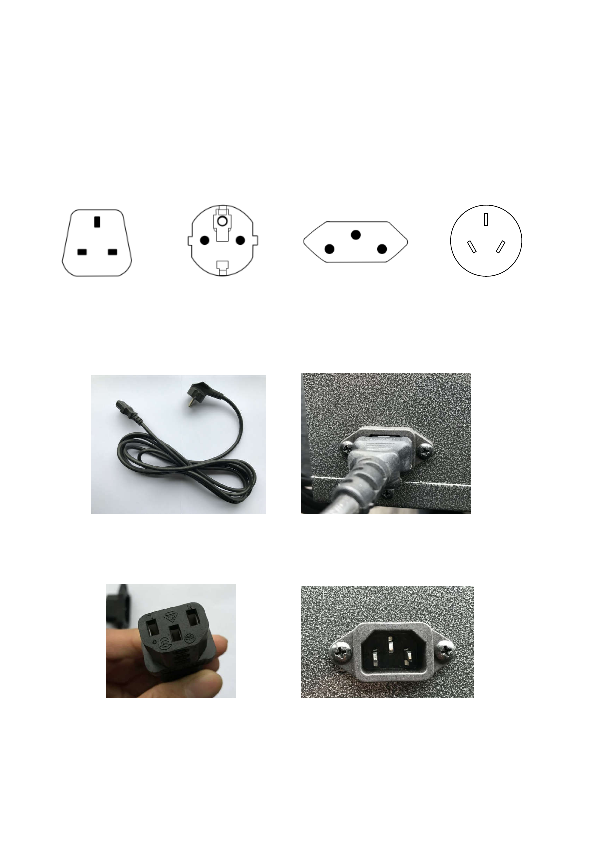
You r po we r co rd w il l c ome se par at e f rom th e un it, please locate it when unpacking your
fireplace. The plug contained inside the box is predetermined at the factory and according to
orders placed by authorized dealers.
Please following the instructions to correctly install the plug into your fireplace.
1. Included in the box will be a power cord similar to the one pictured below. See Picture 1.
2. Hold the male plug and insert it into the female receptacle. The receptacle is locate on
the left side if the fireplace.
3. Please make sure the plugs are firmly connected. See Picture 2 above.
PLUG INSTALLATION
UK plug
European plug
Swiss plug
Picture 1 Picture 2
6
Australian plug
10103060E
10103030E
10103109E
10103087F
Available are UK, European, Swiss & Australian plugs. Should you require any of these
options please contact your dealer for purchase. You will be required to give them the
correct part number as listed below.
Page 7

7
UNPACKI
NG AND TESTING APPLIANCE
Carefully remove the appliance from the box.
Prior to installing the appliance, test to make sure the appliance operates properly by plugging
the power supply cord into a 24
0 Volt grounded outlet.
Test all aspects of its operati
on (manual switches, remote and heater) to make sure all
components are operating correctly.
As with most electronic devices, your new electric fireplace has been designed to operate at
temperatures between 5 ! (41
"
fireplace to reach room temperature before turning it on.
NOTE: There may be trace of odor during the first few minutes of initial use. This is
harmless, normal and will never occur again.
LOCATING THE FIREPLACE
Plan where
to locate and frame the fireplace. This will save time and money later when you
install the fireplace. Before installation consider the following:
1.
Where the fireplace is located must allow for wall and ceiling clearances
2.
Consider a location where the fire
windows or doors.
3.
A 15 ampere, 240 Volt, 50-
60 Hz branch circuit with proper ground must be available at the
location. Preferably a dedicated branch circuit should be provided to avoid circuit breake
to trip of fuses to blow.
) and 35 ! (95"
). During the cold winter
it on.
the following:
place screen will not be exposed to direct sunlight from
e all
months, allow the
from
ilable at the
rs
Page 8
8
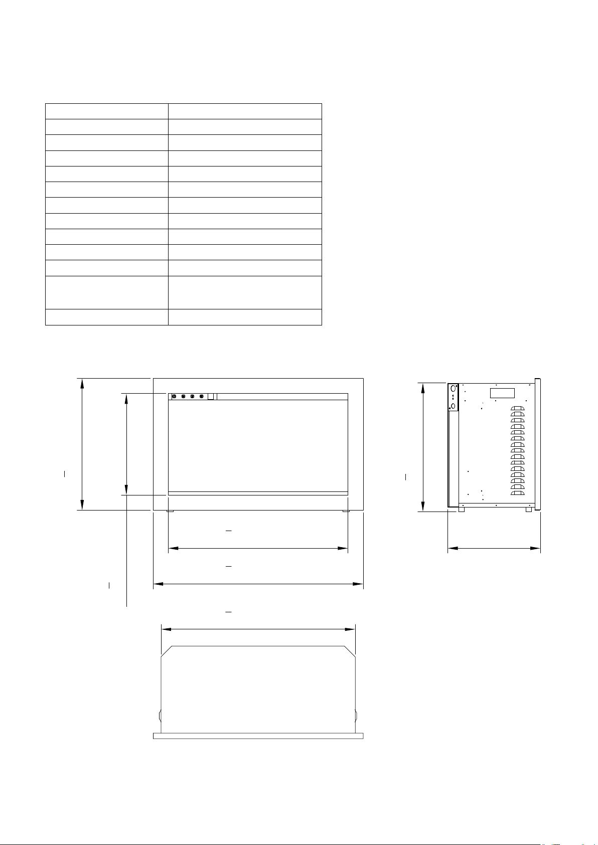
Description
ELECTRIC FIREPLACE
Voltage 120V AC 60Hz
NO HEATER 25W
MOTOR HEATER 19W
Appliance Width 27 3/8" or 69.4 cm
Appliance Height 16 3/4" or 42.5 cm
Appliance Depth 12" or 30.6 cm
Gross Weight 50.7 lbs or 22 kgs
Plug Location Left side
Cord Length 70 7/8” or 180 cm
Rough Wall Opening
TRD - 26
BTU
5118
Size
26 1/4" x 17 1/4"
66.74 cm x 43.77 cm
27
3
8
" [694mm]
23
3
8
" [594mm]
17
1
8
" [435mm]
13
1
4
" [335mm]
16
3
4
" [425mm]
12" [305.8mm]
25
1
4
Watts 1500W Max
220-240V AC 50-60Hz
Page 9
9
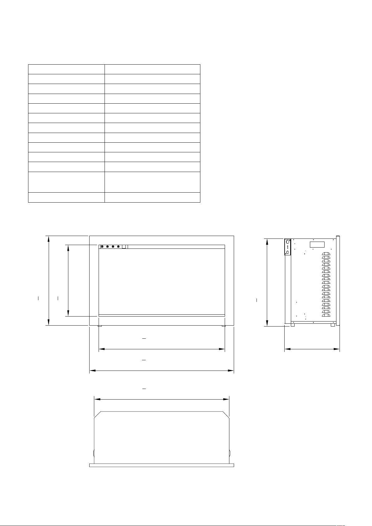
TRD - 30
Description
ELECTRIC FIREPLACE
Voltage
NO HEATER 25W
MOTOR HEATER 19W
Appliance Width 31 1/2" or 79.9 cm
Appliance Height 19 1/8" or 48.5 cm
Appliance Depth 12" or 30.6 cm
Gross Weight 50.7 lbs or 22 kgs
Plug Location Left side
Cord Length 70 7/8” or 180 cm
Rough Wall Opening
BTU
Size
30 3/8" x 19 5/8"
77.24 cm x 49.77 cm
31
1
2
" [799mm]
19
1
2
" [495mm]
15
1
2
" [395mm]
27
1
2
" [699mm]
12" [305.8mm]
19
1
8
" [485mm]
29
3
8
" [747mm]
5118
Watts 1500W Max
220-240V AC 50-60Hz
Page 10

10
TRD - 33
Description
ELECTRIC FIREPLACE
Voltage
NO HEATER 25W
MOTOR HEATER 19W
Appliance Width 33 7/8" or 86 cm
Appliance Height 21 5/8" or 55 cm
Appliance Depth 12" or 30.6 cm
Gross Weight 50.7 lbs or 22 kgs
Plug Location Left side
Cord Length 70 7/8” or 180 cm
Rough Wall Opening
BTU
Size
32 3/4" x 22 1/8"
83.24 cm x 56.27 cm
33
7
8
" [859.4mm]
22
5
8
" [575mm]
18
3
4
" [475mm]
29
7
8
" [759.4mm]
31
3
4
" [807.4mm]
12" [305.8mm]
21
5
8
" [550mm]
5118
Watts 1500W Max
220-240V AC 50-60Hz
Page 11

11
TRD - 38
Description
ELECTRIC FIREPLACE
Voltage
NO HEATER 25W
MOTOR HEATER 19W
Appliance Width 39 1/4" or 99.6 cm
Appliance Height 27 1/4" or 69.1 cm
Appliance Depth 13" or 33.1 cm
Gross Weight 50.7 lbs or 22 kgs
Plug Location Left side
Cord Length 70 7/8” or 180 cm
Rough Wall Opening
BTU
Size
38 1/8" x 27 3/4"
96.94 cm x 70.37 cm
27
1
4
" [691mm]
39
1
4
" [996mm]
35
1
4
" [896mm]
27
5
8
" [701mm]
23
5
8
" [601mm]
13" [330.8mm]
37
1
8
" [944mm]
5118
Watts 1500W Max
220-240V AC 50-60Hz
Page 12

12
TRD - 44
Description
ELECTRIC FIREPLACE
Voltage
NO HEATER 25W
MOTOR HEATER 19W
Appliance Width 45 1/4" or 115 cm
Appliance Height 31 5/8" or 80.3 cm
Appliance Depth 14 3/8" or 36.58 cm
Gross Weight 50.7 lbs or 22 kgs
Plug Location Left side
Cord Length 70 7/8” or 180 cm
Rough Wall Opening
BTU
Size
44 1/4" x 32 1/8"
112.34 cm x 81.57 cm
32" [813mm]
28
1
8
" [713mm]
45
1
4
" [1150mm]
41
3
8
" [1050mm] 14
3
8
" [365.8mm]
31
5
8
" [803mm]
43
1
4
" [1098mm]
5118
Watts 1500W Max
220-240V AC 50-60Hz
Page 13

13
TRD - 48
Description
ELECTRIC FIREPLACE
Voltage
NO HEATER 25W
MOTOR HEATER 19W
Appliance Width 49 1/4" or 115.2 cm
Appliance Height 41 5/8" or 105.7 cm
Appliance Depth 14 3/8" or 36.6 cm
Gross Weight 50.7 lbs or 22 kgs
Plug Location Left side
Cord Length 70 7/8” or 180 cm
Rough Wall Opening
BTU
Size
48 1/4" x 42 1/8"
122.54 cm x 106.97 cm
42" [1067mm]
38
1
8
" [967mm]
49
1
4
" [1252mm]
45
3
8
" [1152mm]
14
3
8
" [365.8mm]
41
5
8
" [1057mm]
47
1
4
" [1200mm]
5118
Watts 1500W Max
220-240V AC 50-60Hz
Page 14

INSTALLATION- BUILT-IN
NOTE: Due to the many different materials used to build walls, it is highly
you consult your local builder before you install this appliance on a wall.
Preparation
1.
Select a location that is not prone to moisture and is located at least 0.91m or 3 feet away
from combustible materials such as curtains, drapes, fur
2.
Mark the desired location on the floor and store the appliance in a safe, dry and dust free
place.
3.
Prepare a wall with a framed opening to accommodate the size of your unit. Leave at least
1/4” (6mm) around the edge of the appl
with local and national codes and other applicable regulations.
Prior to installing, test the appliance to make sure the appliance is fully operational by
plugging the power supply cord into a 120 Volt groun
INSTALLATION
1. Unscrew 4 screws and t
ake off the trim. (NOTE: Keep hold of the front glass as it may fall
down automatically when the trim is removed.)
14
recommended that
his appliance on a wall.
niture, bedding, paper, etc.
iance. Any new wiring must be done in compliance
regulations.
nded outlet.
ss as it may fall
Screws locations
Magnetic stones locations
The rough wall opening size of the fireplace:
W(“)
D(“)
TRD-26 26 1/4
TRD-30 30 3/8
TRD-33 32 3/4
TRD-38 38 1/8
TRD-44 44 1/4 1
5 3/8
TRD-48 48 1/4 1
5 3/8
H(“)
13 17 1/4
13 19 5/8
13 22 1/8
14 27 3/4
32 1/8
42 1/8
Page 15

2.
When the trim is removed, take off the front glass panel.
15
panel.
Inner side panels
3. Unscrew the
screws located on each
side and take off the inner side steel panels.
Page 16

4.
Put the trim back onto the appliance and fasten with screws.(NOTE: This step is to make
sure that the fireplace fits the wall opening well and there is no gap between the trim and the
wall after installation)
5.
Put the fireplace into the wall opening and fix it to the wall by screwing 2 screws each side.
16
Screw the appliance onto the wall
Page 17

6.
Remove the trim following STEP 1. Screw back the inner side steel panels.
7. Put back the front glass pan
el and screw back the trim after you finish the media decoration.
17
ia decoration.
Page 18

18
MEDIA OPTIONS
Your fireplace ships with a 10 piece Birch Log Set, two (2) bags of Smoke Glass, one (1)
bag of Black Vermiculite and one (1) bag of White Vermiculite.
SMOKE GLASS VERMICULITE
11-PIECE BIRCH LOG SET
MEDIA INSTALLATION
Unscrew 4 screws and take off the trim. (NOTE: Keep hold of the front glass as it may fall
down automatically when the trim is removed.)
INSTALLING THE DECORATIVE MEDIA
Pour the fire glass media into the tray. Feel free to use any combination of the fire glass
media that you find most appealing. Put back the trim and front glass after you finish
installing the fire glass.
Screws locations
Magnetic stones locations
Page 19

19
OPER ATION
The fireplace can be operated either by the switches located on the left bottom of the fireplace
unit or by supplied remote control.
Plug the fireplace into a 15 Amp wall socket.
1! Pre ss ke y . Pr es s for th e firs t time "heater work at 1500W, indicator lights red.
Press for the second time, heater work at 750W"indicator lights blue. Press for the
third time, the heating element turns off, indicator extinguishes.
Note: after the heating elements are turned on manually, the heating elements work but
are not controlled by the temperature sensor.
2!Press key . Press for the first time and the charcoal and flame is in the highest
brightness. Press for the second time ,the charcoal and flame is in medium brightness.
Press for the third time ,the charcoal and flame is in low brightness. Press for the fourth time ,
the charcoal and flame goes out. Then it circulates in turn.
MANUAL OPERATION
Page 20

20
REMOTE CONTROL OPER ATION
6 Press“ ”to turn on, turn off and adjust top light colors. The buzzer beeps once when the key is pressed;
1 Press the remote control’s key“ ”, its screen turns on, the flame ignites and the flame icon appears on
the LCD screen of the remote control. Week, time (24h system), and temperature setting are displayed
normally. Press it again, the screen of the remote control will turn off;
2
Key“ ”, flame and charcoal control switch. In case of ON, press once, the flame and the charcoal bed
go out, the LCD screen does not display . Press it again and the flame and the charcoal bed turn on,
the LCD screen displays . The buzzer beeps once when the key is pressed;
3
Press“ (1) ”to adjust the red flame. The buzzer beeps once when the key is pressed;
4 Press“ (2) ” to adjust the yellow flame. The buzzer beeps once when the key is pressed;
5
Press“ (3) ” to adjust the blue flame. The buzzer beeps once when the key is pressed;
1
2
3
Page 21

21
7!Press the heating key“ .” Press for the first time ,the heating elements work at 1500W,
the LCD screen displays , the indicator on the machine lights red. Press a second
time , the heating elements work at 750W, the LCD screen displays , the indicator
on the machine lights blue. Press a third time and the heating elements turn off, the LCD
screen does not display the function icon, the indicator on the machine goes off. The
buzzer beeps once when the key is pressed;
Note: in case the heating elements are turned on by remote control, whether the heating
elements work or not depends on the temperature setting and ambient temperature. They
work only when the temperature setting is above the ambient temperature.
8!Press key“ ”“ ” to adjust the temperature setting between 7 and 30
.
The
buzzer beeps when the key is pressed;
9!Press shift key“ ”. Press once, the corresponding figure flashes. Press “ ” “
”
now to set current time and week. The buzzer does not beep when the key is pressed;
10!Press timing parameter setting key“ .” Press for the first time and the LCD screen
displays to indicate Monday. Now the temperature setting flashes, press “ ” to
set the timing temperature for Monday, press key “ ” to confirm and then press “ ”
the time setting for timing.. The displayed time parameter is “00-23.” Press “ ”
to set the current operating state of timing function; indicates that the timing is on
currently and the control temperature is the temperature setting, indicates that the
timing is on currently and the control temperature is the temperature setting minus 3 ", No
display indicates timing is off current and the heating elements do not work. Corresponding
point flashes when setting. Press for the second time, it displays , set the parameters
Page 22

for Tuesday. Press for the 7th time and it displays . Press for the 8th time and it exits
and recovers to the current week day;
11!Press“ .” Press for the first time and the timing function turns on, the LCD screen
displays
,
the machine’s indicator lights green. Press again to turn off, icon
on the LCD screen goes off. After the timing function is turned on, it works according
the parameter settings. The LCD screen
lights up according to corresponding parameter settings;
Note: when the time, week and timing parameters are changed, you need to switch on-off
the timing key to transfer the timing parameters to the machine. After the machine has
received them correctly, the buzzer will beep once.
12! Press“ ”. Press once to turn on the Open Window function, the LCD screen displays
icon , the indicator on the machine lights yellow. Press again to turn it off, the LCD
screen does not display icon
and
the indicator on the machine goes off. The
buzzer beeps when the key is pressed;
After the Open Window function is turned on, the program firstly detects if the heating
function is turned on. If it is turned on, the program will save the current ambient temperature
value and detects the ambient temperature change once per 12 minutes. When the
decrease in the ambient temperature detected within 30 minutes exceeds 4 ,the
program will deem that the window is open and stop heating, and the Open Window
indicator on the machine will flash rapidly. After it has stopped heating for 70 minutes,
the program starts to detect if the window is closed, and the indicator flashes slowly. It
heats for 6 minutes every 30 minutes (position H2). If the temperature rise is more than 2 ,
the window is considered as closed, and the indicator stops flashing.
22
Page 23

CARE AND MAINTENANCE
CAUTION: Do not use harsh detergents, chemical cleaners or solvents as they may damage the
surface finish of the plastic components.
CONFORMITY WITH DIRECTIVES
Conforms to all relevant European directives
ENVIRONMENTAL PROTECTION
Recycling
This symbol is known as the 'Crossed-out Wheelie Bin Symbol'. When
this symbol is marked on a product or battery, it means that it should not
be disposed of with your general household waste. Some chemicals
contained within electrical/electronic products or batteries can be harmful
to health and the environment.
Only dispose of electrical/electronic/battery items in separate collection
schemes, which cater for the recovery and recycling of materials contained
within. Your co-operation is vital to ensure the success of these schemes
and for the protection of the environment.
1. Switch off and unplug from the power supply before cleaning.
2. Using a soft, moist cloth, with or without a mild soap solution, carefully clean the exterior surface
of the products.
CAUTION: Allow the product to completely cool before handling or cleaning it.
3. Do not allow water or other liquids to run into the interior of the product, as this could create a
fire and/or electrical hazard.
4. We also recommend the periodic cleaning of this appliance by lightly running a vacuum cleaner
nozzle over the guards to remove any dust or dirt that may have accumulated inside or on the
unit.
23
Page 24

24
REPLACEMENT PARTS
This list contains replacement parts
NO. PART NUMBER DESCRIPTION QTY
TRD-26 TRD-30 TRD-33
1 10702245 10702247 10702249
BOTTOM GLASS
2 10701375 10701376 10701377
FRONT CLEAR GLASS
3 3215501 3216501 3217501 TRIM
4
SIDE STEEL PANEL
5 10702244 10702246 10702248
BACK GLASS
6
BOX
7 301506
REMOTE RECEIVER
8 601095F
CIRCUIT BOARD
9 602131B BLOWER AND HEATER
ASSEMBLY
10 10101221C
FLAME MOTOR
11 3085504E 3087504E 3089504E FLICKER ASSEMBLYLED
STRIP
12 601136B 601136B 601136B
LED STRIP
2/2/2
12 601141B 601141B 601141B
LED STRIP
2/2/2
12
LED STRIP
13 10125025
CANOPY LIGHT
14 101050203
REMOTE CONTROL
*Remote control and canopy light are not shown in the exploded view.
Page 25

25
This list contains replacement parts
NO. PART NUMBER DESCRIPTION QTY
TRD-38 TRD-44 TRD-48
1 10702251 10701379 10702255
BOTTOM GLASS
2 10701378 10701379 10701380
FRONT CLEAR GLASS
3 3218501 3219501 3220501 TRIM
4
SIDE STEEL PANEL
5 10702250 10702252 10702254
BACK GLASS
6
BOX
7 301506
REMOTE RECEIVER
8 601095F
CIRCUIT BOARD
9 602131B BLOWER AND HEATER
ASSEMBLY
10 10101221C
FLAME MOTOR
11 3218507 3219507 3220507 FLICKER ASSEMBLYLED
STRIP
12 601136B 601136B 601136B
LED STRIP
3/2/2
12 601137B 601137B 601137B
LED STRIP
0/1/1
12 601141B 601141B 601141B
LED STRIP
3/3/3
13 10125019 10125021 10125021
CANOPY LIGHT
14 101050203
REMOTE CONTROL
*Remote control and canopy light are not shown in the exploded view.
Page 26

26
EXPLODED VIEW
\
\
\
\
3
1
2
4
4
5
6
8
9
11
10
12
7
Page 27

27
TROUBLE SHOOTING
PROBLEM POSSIBLE CAUSE SOLUTION
Dim or no flame Flame LED’s are burnt out. Inspect the LED’s and replace them if
necessary.
Back black cloth is falling off
and rolled up in the flicker.
Change a flicker and back black cloth.
Ember bed is not
glowing or dimming
Ember LED’s are burnt out Inspect the ember bed LED’s and
replace them if necessary.
Appliance turns off and
will not turn on
Appliance has overheated, and
safety device has caused the
thermal switch to disconnect.
Turn off the main switch, allow
appliance to cool for 10 minutes,
turn back on.
House
tripped.
circuit breaker has Reset house circuit breaker.
Appliance’s fuse has blown. Replace the fuse.
Appliance will not come
on when switch is
flipped to ON
Appliance is not plugged into an
electrical outlet.
Check plug and plug in.
Appliance has overheated and
safety device has caused the
thermal switch to disconnect.
Turn off the main switch, allow
appliance to cool for 10 minutes, turn
back on.
Circuit board is burnt out. Inspect the circuit board and replace
it if necessary.
No warm air coming out
of appliance
Heater is burnt out. Inspect the burner and heater
assembly and replace it if necessary.
Flame sputters Flame motor is defective. Call a qualified service technician and
replace flame motor.
Remote Control does
not work.
Low batteries.
Unit switch in “O” position.
Replace AAA batteries in remote
control.
Turn the switch in “I” position.
Flame is fixed. Wiring may be loose or the
flame motor may be defective.
Page 28

28
SERVICE HISTORY
This heater must be serviced annually depending on usage.
Date Dealer
Name
Service technician
Name
Service Performed Special Concerns
NOTES:
Page 29

WARRANTY FOR PRODUCTS MANUFACTURED AFTER JANUARY 1st, 2016
Amantii Imports Corp. ("Amantii " ) warrants that your newly purchased Amantii electric fireplace is free from manufacturing and material defects
for a period of two (2) years from the date of the first purchase, subject to the conditions and limitations contained below.
Warranty Application & Exclusions
This limited warranty applies to your newly purchased Amantii electric fireplace; the limited warranty's application is limited to purchases made in
any province of Canada or in any of the 52 States of the United States of America, including the District of Columbia. Only the original purchaser
of the product is eligible for coverage under this limited warranty; the warranty is not transferable.
Products excluded from this limited warranty
Light bulbs are not covered by this limited warranty and are the sole responsibility of the owner/ purchase r. Amantii does not cover service or
labor charges.
Warranty Coverage and Term
Products covered by this limited warranty have been tested and inspected prior to shipment and, subject to the provisions of this warranty,
Amantii warrants such products to be free from defects in material and workmanship for a period of two (2) years from the date of the first
purchase of such products.
The limited two (2) year warranty period for products also applies to any implied warranties that may exist under applicable law. Some
jurisdictions do not allow limitations on how long an implied warranty lasts, so the above limitation may not apply to the purchaser.
All other warranties-expressed or implied-with respect to the product, its components and accessories or any obligation/liabilities on the part
of Amantii are hereby expressly excluded.
Limitations to Coverage Under Limited Warranty
This limited warranty does not apply to products that have been repaired, except by Amantii or its authorized service representatives, or
otherwise altered. This limited warranty further does not apply to defects resulting from misuse, abuse, accident, neglect, incorrect installation,
improper maintenance or handling, or operation with an incorrect power source. Products made by other manufacturers, sold with the product
or thereafter, are not covered by this limited warranty. The use of unauthorized components will render this warranty null and void.
Panorama Outdoor Units
All Panorama units that are installed outdoors or in moisture intense conditions must use the stainless steel cover. Proof of purchase of the cover
is required for any warranty claims.
Defects
Defects must be brought to the attention of the selling dealer. Please have your proof of purchase, catalogue/model and serial numbers available
when contacting dealer; any and all service under the limited warranty requires a proof of purchase of the product. Should a product or part
covered by this limited warranty be proven to be defective, in material or workmanship, and during the two (2) year limited warranty period,
Amantii will replace such defective product or part without charge. If Amantii is unable to replace such product, or if replacement is not
commercially practicable or cannot be timely done, in its sole discretion Amantii may
, in lieu of replacement, choose to refund the purchase price
for such product or part. Amantii does not cover labor or service charges to replace said parts.
Limitations
In no event will Amantii, including without limitation any of its directors, officers, shareholders, employees, consultants, agents, heirs, executors,
administrators and assigns, be liable to the purchaser or any third party, whether in contract, in tort, or on any other basis for any indirect , special,
punitive, exemplary, consequential, or incidental loss, cost or damage arising out of or in connection with the sale, maintenance, use or inability
to use the product, even if Amantii, including without limitation any of its directors, officers, shareholders, employees, consultant s, agents, heirs,
executors, administrators and assigns, have been advised of the possibility of such losses, costs or damages, or if such losses, costs or damages
are foreseeable. In no event will Amantii, including without limitation any of its directors, officers, shareholders, employees, consultants, agents, heirs,
executors, administrators and assigns, be liable for any direct losses, costs or damages that exceed the purchase price of the product.
Some jurisdictions do not allow the exclusion or limitation of incidental or consequential damages, so t he a bo ve l im i t at i o n o r ex c lu si o n m a y no t
apply to the purchaser.
Application of Provincial and State Law
This limited warranty gives you specific legal rights, and you may also have other rights which vary from jurisdiction to jurisdiction. The provisions
of the United Nations Convention on Contracts for the Sale of Goods shall not apply to this limited warranty or the sale of products covered by
this limited warranty
.
General
Amantii reserves the right to make changes at any time without notice, in design, material, specifications, prices and the right to discontinue styles
and products.
Amantii Electric Fireplaces• 502-1027 Davie Street• Vancouver, BC V6E4L2
Effective January 1, 2016
29
 Loading...