

Page 1
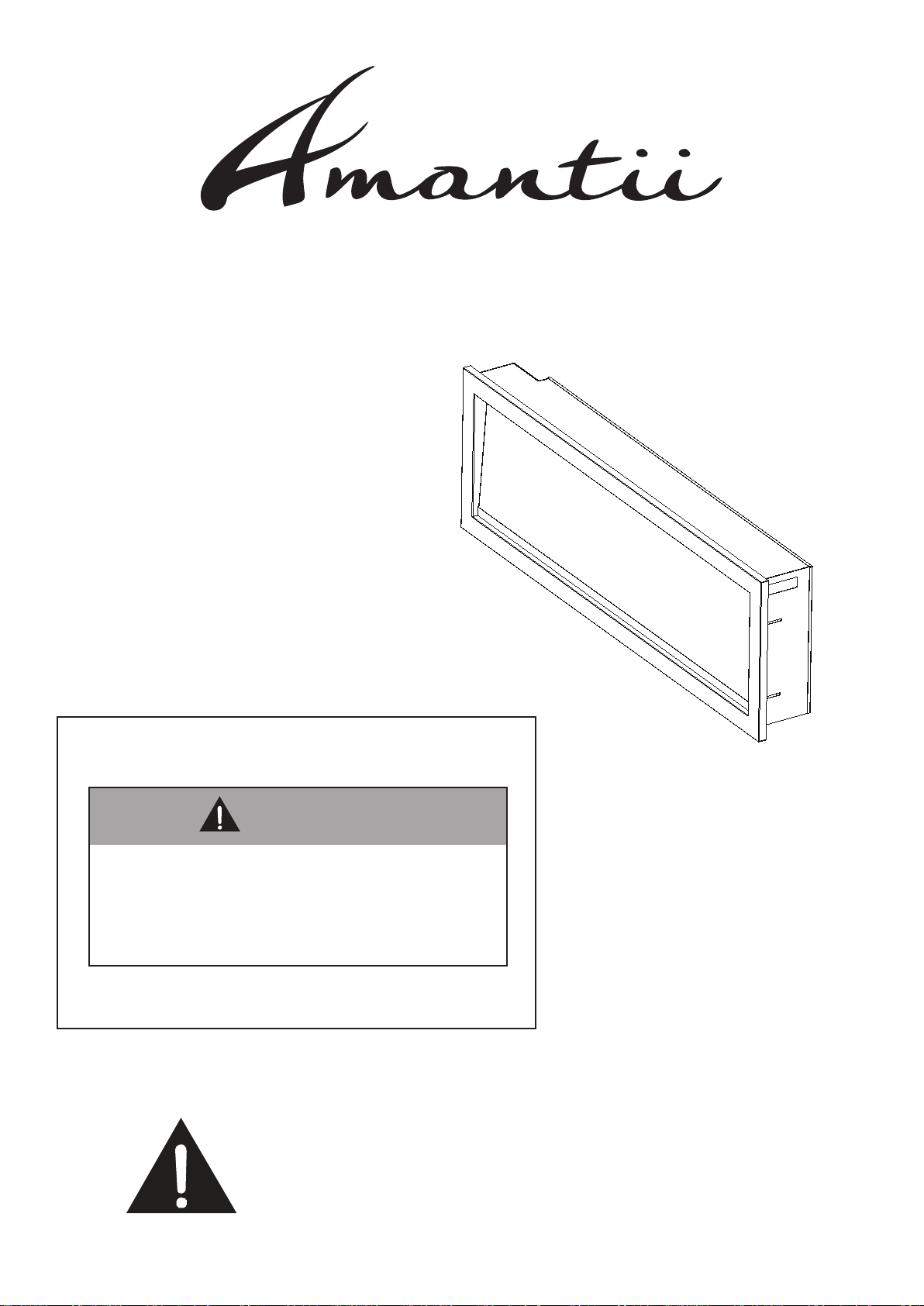
ELECTRIC FIREPLACE
www.amantii.com
INSTALLATION AND OPERATION INSTRUCTIONS FOR
SYM-34 BESPOKE
BS1900034-1
SYM-42 BESPOKE
BS1900042-1
SYM-50 BESPOKE
BS1900050-1
SYM-60 BESPOKE
BS1900060-1
SYM-74 BESPOKE
BS1900074-1
SYM-88 BESPOKE
BS1900088-1
SYM-100 BESPOKE
BS1900100-1
SAFETY INFORMATION
WARNING
if the information in these instructions
are not followed exactly, a fire or
explosion may result causing property
damage, personal injury or loss of life.
Do not store or use gasoline or other flammable vapors
and liquids in the vicinity of this or any other.
INSTALLER: LEAVE THIS MANUAL WITH THE APPLIANCE.
CONSUMER: RETAIN THIS MANUAL FOR FUTURE REFERENCE.
WARNING: This product can expose you to chemicals including
lead in the wiring, which is [are] known to the State of California
to cause birth defects of other reproductive harm. For more
information visit: www.p65warnings.ca.gov
1
Page 2

TABLE OF CONTENTS
Please read and carefully follow all of the instruction found in this manual. Please pay special
attention to the safety instructions provided in this manual. The instructions included here will
assure that you have many years of dependable and enjoyable service from your Amantii product.
IMPORTANT INSTRUCTIONS
CAUTIONS
UNP ACKING AND TESTING APPLIANCE
GROUNDING APPLIANCE
LOCATING THE FIREPLACE
PRODUCT SPECIFICATION
OUTDOOR INSTALLATIONS
INSTALLATION-WALL MOUNT
INSTALLATION- BUILT-IN
HARD- WIRE INSTALLATION
DECORATIVE MEDIA INSTALLATION
MANUAL OPERATION
REMOTE CONTROL OPERATION
TROUBLE SHOOTING
3
4
5
5
5
6
8
9
10
13
14
15
16
18
REPLACEMENT PARTS
EXPLODED VIEW
19
21
2
Page 3

1. Read all instructions before installing or using this heater.
2. Keep combustible materials, such as furniture, pillows, bedding, papers, clothes and curtains at
least 3 feet from the front, sides and rear of the heater.
3. Always unplug heater when not in use.
4. Do not operate the fireplace if it has a damaged cord or plug, after it has malfunctioned, or if the
unit has been dropped or damaged in any way.
5. Do not run the cord under carpeting. Do not cover the cord with throw rugs, runners or anything
else. Arrange the cord away from traffic areas where it could not be tripped over.
6. To disconnect the heater, turn the controls to "OFF" before removing the plug from the outlet.
7. Do not insert or allow foreign objects to enter any ventilation or exhaust opening, as this may
cause an electric shock, fire or damage to the heater.
8. To prevent a possible fire, do not block air intakes in any manner.
9. A heater has hot and arcing or sparking parts inside. Do not use it in areas where gasoline,
paint or flammable liquids are used or stored.
10. Use this heater only as described in this manual. Any other use not recommended by the
manufacturer may cause fire, electric shock or injury.
11. Avoid the use of an extension cord, the extension cord will overheat and cause a fire. This
heater is not to be used with an extension cord.
12. Always use properly grounded fused and polarized outlets.
13. Always use ground fault protection where it is required by electrical codes.
14. Always disconnect the power before performing any cleaning, maintenance or relocation of the
heater.
15. To prevent a possible fire, do not burn wood or other materials in this heater.
16. To prevent electric shock or fire, always use a certified electrician, should new circuits or
outlets be required.
17. When transporting or storing the heater, keep it in a dry place, free from excessive vibration.
18. This appliance should not be modified under any circumstances.
19. Packaging material should be kept away from children and be disposed of in a safe manner.
Plastic bags are not toys and should be kept away from children and infants.
20. Do not use this heater in small rooms when they are occupied by persons not capable of
leaving the room on their own, unless constant supervision is provided.
21. If the glass is damaged, do not use the heater in order to avoid a hazard.
22. Do not leave children unsupervised where heater is turned on.
23. CAUTION Some parts of this product can become very hot and cause burns. Particular attention has to be given where children and vulnerable people are present.
SAVE THESE INSTRUCTIONS
3
Page 4
CAUTIONS
Always install the heater in accordance with this guide. If in doubt obtain
expert advice.
Always make sure the electrical socket is accessible and located adjacent
to, but not above the heater.
Always disconnect the heater from the electrical supply before moving it, or
Do’s
Don’ts
carrying out cleaning, maintenance.
Always make sure the heater is firmly secured to prevent it from being
tipped over.
Always use a fireguard when young children and infirm persons can come
into contact with the heater.
Never leave children unsupervised in a room where the heater is ON and
unguarded.
Never obstruct or cover the fan outlet or force items into heater openings.
Never use aerosols or steam cleaners on or around the heater.
Never route the main supply cable under carpet etc.
Never install the heater close to curtains or combustible materials.
Never use the heater to dry clothes etc.
Never sit or stand on the heater.
4
Page 5
UNPACKING AND TESTING APPLIANCE
Carefully remove the appliance from the box.
Prior to installing the appliance, test to make sure the appliance operates properly by plugging the
power supply cord into a 120 Volt grounded outlet.
Test all aspects of its operation (manual switches, remote and heater) to make sure all
components are operating correctly.
As with most electronic devices, your new electric fireplace has been designed to operate at
temperatures between 5 ℃(41℉) and 35℃ (95℉). During the cold winter months, allow the
fireplace to reach room temperature before turning it on.
NOTE: There may be trace of odor during the first few minutes of initial use. This is
harmless, normal and will never occur again.
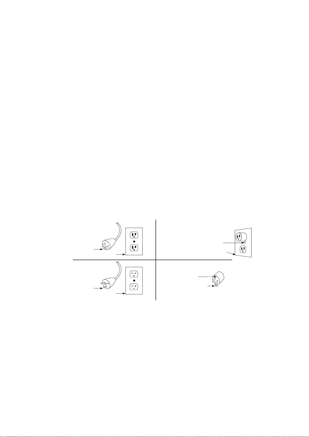
GROUNDING APPLIANCE
This appliance is for use on 120 Volts. The cord has a plug as shown in (A). An adapter as
shown in (C) is available for connecting three-blade grounding type plugs to two-slot. The green
grounding lug extending from the adapter must be connected to a permanent ground such as a
properly grounded outlet box. The adapter should not be used if a three-slot grounded receptacle
is available.
To disconnect appliance, turn controls to off, then remove plug from outlet.
A B
Metal Screw
Grounding Pin
Cover of Grounded Outlet Box
Cover of Grounded Outlet Box
CD
Adapter
Grounding Pin
Cover of Grounded Outlet Box
Grounding Lug
LOCATING THE FIREPLACE
Plan where to locate and frame the fireplace. This will save time and money later when you install
the fireplace. Before installation consider the following:
1. Where the fireplace is located must allow for wall and ceiling clearances.
2. Consider a location where the fireplace screen will not be exposed to direct sunlight from
windows or doors.
3. A 15 ampere, 120 Volt, 60 Hz branch circuit with proper ground must be available at the
location. Preferably a dedicated branch circuit should be provided to avoid circuit breakers to trip
of fuses to blow.
5
Page 6
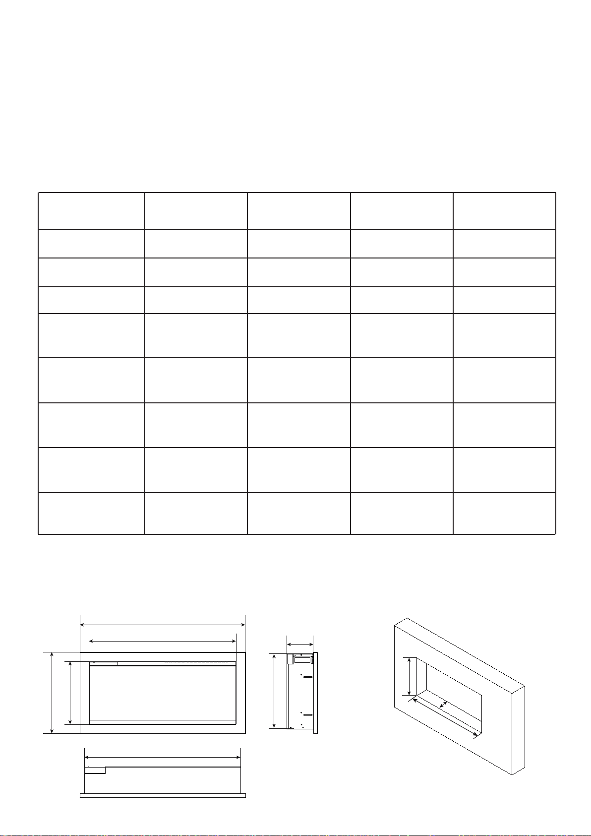
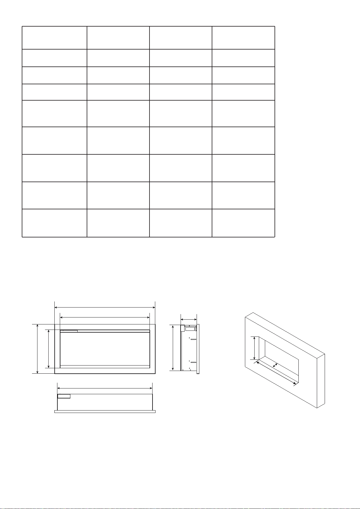
PRODUCT SPECIFICATION
This appliance has been tested in accordance with the UL Standard 2021 for fixed and location
dedicated electric room appliances in the United States and Canada. If you need assistance
during installation, please contact your local dealer.
NOTE: This appliance must be electrically wired and grounded in accordance with local
codes. In the absence of local codes, use the current CSA C22.1 Canadian Electrical Code
in Canada or the ANSI/NFPA 70 National Electrical Code in the United States.
product model
Voltage
Watts
BTU
Appliance size
(W x H x D)
Glass Viewing
(W1 x H1 )
Frame size
(W2 x H2 )
Wall Opening Size
(W3 x H3 x D3 )
BS1900034-1
(SYM-34 BESPOKE)
120V AC 60Hz
1500W Max 1500W Max 1500W Max 1500W Max
4095 4095 4095 4095
32 3/8”x 15 5/8” x 5 1/2”
82.3 x 39.6 x 14 cm
30 5/8” x 13 1/8”
77.7 x 33.2 cm
34 1/2” x 16 7/8”
87.5 x 43 cm
32 7/8” x 16” x 6”
83.5 x 40.6 x 152 cm
BS1900042-1
(SYM-42 BESPOKE)
120V AC 60Hz 120V AC 60Hz 120V AC 60Hz
42 1/4”x 15 5/8” x 5 1/2”
112.5 x 39.6 x 14 cm
40 3/8” x 13 1/8”
102.7 x 33.2 cm
44 1/4” x 16 7/8”
112.5 x 43 cm
42 3/4” x 16” x 6”
108.6 x 40.6 x152 cm
BS1900050-1
(SYM-50 BESPOKE)
50 1/4”x 15 5/8” x 5 1/2”
127.6 x 39.6 x 14 cm
48 1/2” x 13 1/8”
123.1 x 33.2 cm
52 1/4” x 16 7/8”
132.7 x 43 cm
50 3/4” x 16” x 6”
128.9 x 40.6 x152 cm
(SYM-60 BESPOKE)
60 1/4”x 15 5/8” x 5 1/2”
153 x 39.6 x 14 cm
154.3 x 40.6 x152 cm
BS1900060-1
58 3/8” x 13 1/8”
148.4 x 33.2 cm
58 3/8” x 16 7/8”
112.5 x 43 cm
60 3/4” x 16” x 6”
Cord Length
H2 H1
70.9” < L < 95.5”
180 cm < L < 240 cm
W2
W1
W
70.9” < L < 95.5”
180 cm < L < 240 cm
D
H
70.9” < L < 95.5”
180 cm < L < 240 cm
H
W
70.9” < L < 95.5”
180 cm < L < 240 cm
D
6
Page 7
product model
BS1900074-1
(SYM-74 BESPOKE)
BS1900088-1
(SYM-88 BESPOKE)
BS1900100-1
(SYM-100 BESPOKE)
Voltage
Watts
BTU
Appliance size
(W x H x D)
Glass Viewing
(W1 x H1 )
Frame size
(W2 x H2 )
Wall Opening Size
(W3 x H3 x D3)
Cord Length
120V AC 60Hz
1500W Max 1500W Max 1500W Max
4095 4095 4095
74 1/4” x 15 5/8” x 5 1/2”
188.5 x 39.6 x 14 cm
72 3/8” x 13 1/8”
184 x 33.2 cm
76 1/4” x 16 7/8”
193.7 x 43 cm
74 3/4” x 16” x 6”
189.9 x 40.6 x 152 cm
70.9” < L < 95.5”
180 cm < L < 240 cm
120V AC 60Hz 120V AC 60Hz
88 1/4” x 15 5/8” x 5 1/2”
224.1 x 39.6 x 14 cm
86 3/8” x 13 1/8”
219.5 x 33.2 cm
90 1/4” x 16 7/8”
229.3 x 43 cm
90 1/4” x 16” x 6”
229.3 x 40.6 x 152 cm
70.9” < L < 95.5”
180 cm < L < 240 cm
100 1/4” x 15 5/8” x 5 1/2”
254.6 x 39.6 x 14 cm
98 3/8” x 13 1/8”
250 x 33.2 cm
102 1/4” x 16 7/8”
254.6 x 43 cm
100 3/4” x 16” x 6”
254.6 x 40.6 x 152 cm
70.9” < L < 95.5”
180 cm < L < 240 cm
H2 H1
W2
W1
W
D
H
H
D
W
7
Page 8

OUTDOOR INSTALLATIONS
The Symmetry Bespoke Series electric fireplaces are suitable for installation in outdoor areas
protected from direct water impingement. In addition to maintaining the listed mantel and
combustibles clearances, a rain protection overhang factor of 1/2 shall be constructed to the front
and to each side of the installed appliance. See illustration below. All wiring connections to line
power shall be in accordance with local building code requirements. Inquires about local codes
and regulations must be done prior to installation.
The overhang(A) must extend at least 1/2 the roof-line height. Height is measured from the base
of the fireplace.
For example: if the roof-line(B) is 8” above the base of the fireplace, the overhang(A) must be at
least 4”.
8
Page 9

INSTALLATION-WALL MOUNT
NOTE: Due to the many different materials used to build walls, it is highly recommended that you
consult your local builder before you install this appliance on a wall.
1. Select a location that is not prone to
moisture and is located at least 0.91 m or 3
feet away from combustible materials such
as curtains or drapes, furniture, bedding,
paper, etc.
2. Using a spirit level to select a position in
which to mount the heater horizontally. See
Figure 1.
3. Check the wall to ensure there is no
wiring, pipe wires etc in the area to be
drilled. Drill 6 or more holes depending on
the size of he unit purchased, using a
suitable size drill bit and insert the wall
plugs into the holes.
Fig 2
4. Remove the hanger from the fireplace by
removing the screws. See Figure 2.
5. Fasten the hanger to the wall. See
Figure 3.
6. To prevent fireplace from moving, use
the provided safety screw to fasten the
fireplace to the wall. See Figure 4.
WARNING: Be sure that the bolts have
been fixed firmly enough to withstand
the weight!
≥2”
Fig 3
≥2”
FLOOR
≥2”
≥2”
Fig 4
Fig 1
9
Page 10

INSTALLATION- BUILT-IN
NOTE: Due to the many different materials used to build walls, it is highly recommended that you
consult your local builder before you install this appliance on a wall.
PREPARATION
Select a location that is not prone to moisture and is located at least 0.91m or 3 feet away from
combustible materials such as curtains, drapes, furniture, bedding, paper, etc.
2. Mark the desired location on the floor and store the appliance in a safe, dry and dust free place.
3. Prepare a wall with a framed opening to accommodate the size of your unit. Leave at least 1/4”
(6mm) around the edge of the appliance. Any new wiring must be done in compliance with local
and national codes and other applicable regulations.
Prior to installing, test the appliance to make sure the appliance is fully operational by plugging the
power supply cord into a 120 Volt grounded outlet.
THE ROUGH WALL OPENING SIZE OF THE FIREPLACE PLEASE REFER TO THE PRODUCT
SPECIFICATION SHEET.
INSTALLATION
1. Unscrew 4 screws (The quantity varies depending on the size of the unit) and take off the
trim. (NOTE: Keep hold of the front glass as it may fall down automatically when the trim is
removed.)
screws locations
magnetic stone locations
10
Page 11

2. When the trim is removed , take off the front glass panel.
3. Unscrew the 2 screws located on each side and take off the inner side steel panels.
4. Put the trim back onto the appliance and fasten with screws.(NOTE: This step is to make sure
that the fireplace fits the wall opening well and there is no gap between the trim and the wall after
installation)
11
Page 12

5. Put the fireplace into the wall opening and fix it to the wall by screwing 2 screws each side.
6. Remove the trim following STEP 1. Screw back the inner side steel panels.
7. Put back the front glass panel and screw back the trim after you finish the media decoration.
12
Page 13

HARD- WIRE INSTALLATION
Turn off the appliance completely and let cool before servicing. Only a qualified service person
should service and repair this electric appliance.
If it is necessary to hard-wire this appliance, a qualified electrician must remove the cord
connection, and wire the appliance directly to the house hold wiring.
This appliance must be electrically connected and grounded in accordance with local codes, if
hard-wired. In the absence of local codes, use the current CSA C22.1 CANADIAN ELECTRICAL
CODE in Canada or the current ANSI/NFPA 70 NATIONAL ELECTRICAL CODE in the United
States.
1. Remove the cover plate from the back top right corner of the appliance by removing the four
screws, as shown below. Unscrew and remove power cord.
2. Attach the wiring to the junction block. Please make sure the live wire goes into the “L”, the
neutral wire into “N” and the ground wire into “G”.
N G L
3. Return the cover plate to the back top right corner and screw the four screws back in to fasten
the plate.
13
Page 14

DECORATIVE MEDIA INSTALLATION
Consumers may purchase optional decorative media if they choose. See dealer for more details.
1. Unscrew 4 screws (Tthe quantity varies depending on the size of the unit) and take off the
trim. (NOTE: Keep hold of the front glass as it may fall down automatically when the trim is
removed.)
screws locations
magnetic stone locations
2. When the trim is removed , take off the front glass panel.
3. Pour the media into the tray. Feel free to use any combination of the fire glass media that you
find most appealing. Put back the trim and front glass after you finish installing the media.
14
Page 15

MANUAL OPERATION
The fireplace can be operated either by the touch panel located on the left front top side of the
fireplace or by supplied remote control.
Ensure that the ON / OFF Power Switch on the fireplace is in the ON position.
Touch the control panel once to “wake up” the controls. This will cause the controls to light up. At
this time, you can press the power button to turn on fireplace
1. Press “ ” to turn on and off the fireplace.
2. Press “ ” to adjust the flame brightness. There are 6 brightness levels(L6-L1)and an
off(OF) position. Each time the flame button is pressed, the brightness of the flame decrease.
press the flame button for 10 seconds, the timing indicator light on and will rapidly blinks, at this
time, You can use the TuyaSmart APP to connect to the fireplace.
3. Press “ ” to adjust the ember bed brightness. There are 7 brightness levels (d8-d2), dynamic condition(d1) ,and the OFF(OF) setting you can cycle through. Each time the ember bed button
is pressed, the brightness of the ember bed decrease. when in off position, turn on the heat the
ember bed will turn red to indicate that the heating function is on.
4. Press “ ” for the first time to display the current timing,press the button again to clear the
current timing. If the timing in off position, the second press will show 30. Multiple times to set
operating duration to OF, 30 min, 1h, 2h, 3h, 4h, 5h, 6h, 7h, 8h.
Press and hold the “ ” for 5 seconds to turn on the sound.
5. Press “ ” for the first time to display the current setting temperature,press the button again
to clear the current temperature. If the heater in off position, the second press will show 22.
Multiple times to set ambient temperatures at 22℃(72℉), 23℃(74℉),24℃(76℉), 25℃(78℉), 26
℃(80℉), 27℃(82℉), 28℃(84℉),15℃(52℉), 16℃(54℉), 17℃(56℉),18℃(58℉), 19℃(60℉), 20
℃(62℉), 21℃(64℉).
Temperature unit convert function: When the heater is on, press and hold the“ ” Button for 5
seconds, current temperature unit display will convert to another temperature unit.
15
Page 16

REMOTE CONTROL OPERATION
For remote to function make sure the fireplace is plugged in and the ON / OFF Power Switch on
the fireplace is in the ON position and the remote has batteries.
Important: When operating the remote make sure you point the remote to the center of the
fireplace. Each time you press the button, there will be a beep tone emitted.
Setting the current time of the remote control
You must press the key to open the remote control and press the key to enter the setting
current time state. When one of the “Sun”“ Mon”“Tue”“Wed”“Thu”“Fri”“Sat” date is flashing, you
can press the or key to select the current day of the week, and press the key to confirm and enter hour setting. When the digital tube of time hour flashes, press the or key to
set the current time and press the key to confirm and enter minute setting. When the digital
tube of time minute flashes, press the or key to set the current time and press the
key to confirm.
This Power Button turn the fireplace on and off. It has a
memory function, press the power button once to turn
power on. Pressing the power button again will turn the
power off.
The Timer Button has adjustable setting at range from 30
minutes to 8 hours. As shown the following: 0:30- 1:001:30- 2:00- 2:30- 3:00- 3:30- 4:00- 4:30- 5:00- 5:30- 6:006:30- 7:00-7 :30- 8:00. Once you have set the timer, The
icon will be displayed on the LCD screen of the remote
control. Press this button again, cancel the timing setting,
and the icon disappears.
When the timer is up, it will close all the functions and
enter standby mode. In this mode, you should touch the
power icon to restart the appliance.
Each time the Heater Button is pressed, the power of the
heater will change. As shown the following: H1- H2AUTO(22℃)- OFF(no display).
H1 means the firepalce on Low Heat.
H2 means the fireplace on high heat.
AUTO means fireplace can automatically adjust to the
temperature you set. When in AUTO, you can set the
desired temperature with or keys. You can
switch temperature unit between Celsius and Fahrenheit
with or keys.
16
Page 17

Each time Speed Button is pressed, the speed of the flame will change. Three options are
available: Medium- High- Low.
The Moodlight Button turn the moodlight on and off. When in on position, the display
screen of the remote control shows AD 1, when the number “1” flash, you can set the color
of moodlight with or keys. There are 10 different moodlight colors(AD1-10) and
dynamic condition(AD11) to choose from.
The Ember Bed Button turn the Ember bed light on and off. When in on position, the
display screen of the remote control default shows 8 8 8. You can press or or
keys to change the corresponding color.
Each time the Red Button is pressed the brightness of the red color decrease. There
are 7 brightness levels (8-2), dynamic level(1) and OFF ( no display) settings that can
be cycled through. When no number is displayed on the remote control LCD screen
then the ember bed color is off.
Each time the Green Button is pressed the brightness of the green color decrease.
There are 7 brightness levels (8-2), dynamic level(1) and OFF ( no display) settings
that can be cycled through. When no number is displayed on the remote control LCD
screen then the ember bed color is off.
Each time the Blue Button is pressed the brightness of the blue color decrease. There
are 7 brightness levels (8-2), dynamic level(1) and OFF ( no display) settings that can
be cycled through. When no number is displayed on the remote control LCD screen
then the ember bed color is off.
The Flame Button turn the Flame on and off. When in on position, the LCD screen of the
remote control default shows 6 6 6. You can press or or key to change the
corresponding color.
Each time the Red Button is pressed the brightness of the red color decrease. There
are 6 brightness levels (6-1) and OFF ( no display) settings that can be cycled
through. When no number is displayed on the remote control LCD screen then the
flame color is off.
Each time the Orange Button is pressed the brightness of the orange color decrease.
There are 6 brightness levels (6-1) and OFF ( no display) settings that can be cycled
through. When no number is displayed on the remote control LCD screen then the
flame color is off.
Each time the Yellow Button is pressed the brightness of the yellow color decrease.
There are 6 brightness levels (6-1) and OFF ( no display) settings that can be cycled
through. When no number is displayed on the remote control LCD screen then the
flame color is off.
17
Page 18

7 day timer function
NOTE: Ensure that the clock has been set correctly first, otherwise timer will not work.
Press key once, 7 days from Monday to Sunday will display on the LCD screen of the
remote control, press key within 5 seconds to enter 7 day timer function . When “Sun”
is flashing use the or key to select the day that you want to set,pressing key
to confirm. Then “ON” will be display on the LCD screen of the remote control, at the same
time, digital tube of time hour flashes, press the or key to set the time to turn the
fireplace on. After setting the startup time, “OFF” will be displayed on the LCD screen. Also
use the or key to set the shutdown time. After setting the shutdown time, “AUTO” will
be display on the LCD screen of the remote control, and digital tube of temperature flashes.
At this time, you can set the desired temperature with or keys, or press the key
to choose low heat (H1) or high heat(H2). Now, the time to turn on and off is set.
When the 7 day timer is set, the icon will be displayed on the LCD screen of the
remote control. Then press the key again to cancel the 7 day timer and the icon will
disappears.
NOTE: If the 7 day timing and general timing exist at the same time, the shutdown time shall be
the earlier time. For example, it is now 6am on tuesday, turn on the heater and set the shutdown
time after 4 hours (i.e. 10 am), while the previous 7 day shutdown time is 8 am on tuesday, so
today's heater shutdown time is 8 am instead of 10 am.
The Refer Button turn on or off query 7-day timer setting. Query only, not change. Press the
or key to query the timing status of the day of the week. Press the or key
to query the startup time and shutdown time.
Press key once to enter the query state, press key again to exit the query statu.
This button turns sound on or off.
TROUBLE SHOOTING
Fault code Fault Cause Solution
E1 The heater overheating
E2 NTC is defective. Call after-sales service.
Call after-sales service.
E3
Each time the heater button is pressed in the E1 state, one beep tone will be given.
Each time the heater button is pressed in the E2 state, two beeps tone will be given.
Each time the heater button is pressed in the E3 state, three beeps tone will be given.
The heater not working.
If the vents are dirty or clogged. Unplug the power,
clean the dust and debris of the vent area. Wait for 5
minutes, plug in and turn on the heater. If the heater
still don't work, please call after-sales service.
18
Page 19

REPLACEMENT PARTS
PART NUMBER
NO. DESCRIPTION
1 1
2
3
4
5
6
7
FRONT GLASS 60000190
EMBER BED GLASS
FLAME EFFECT GLASS
LED STRIP
FOR EMBER BED
LED STRIP
FOR FLAME
PCB BOARD
MOTOR
BS1900034-1
(SYM-34 BESPOKE)
60000187
60000189
60000188
30001812
30001961
30001981
30001984
30001868
BS1900042-1
(SYM-42 BESPOKE)
60000193
60000195
60000194
30001859
30001981
30002008
30001984
30001868
BS1900050-1
(SYM-50 BESPOKE)
60000192
60000191
30001812
30001859
30002056
30001984
30001868
BS1900060-1
(SYM-60 BESPOKE)
60000196
60000198
60000197
30001961
30001859
30002059
30001984
30001868
QTY
1
1
1
1
1
1
8
9
10
BLOWER AND
HEATER ASSEMBLY
LED STRIP
FOR TOP LIGHT
30002019
30001982 30002012
30001978 3000197830001978 30001978AC ADAPTER
30002019
30002010 30002013
3000201930002019
1
1
1
19
Page 20

REPLACEMENT PARTS
PART NUMBER
NO. DESCRIPTION
1
2
3
4
5
6
7
FRONT GLASS 60000205
EMBER BED GLASS
FLAME EFFECT GLASS
LED STRIP
FOR EMBER BED
LED STRIP
FOR FLAME
PCB BOARD
MOTOR
BS1900074-1
(SYM-74 BESPOKE)
60000199
60000201
60000200
30001812
30001961
30001959
30001981
30001984
30001868
BS1900088-1
(SYM-88 BESPOKE)
60000202
60000204
60000203
30001812
30001961
30001959
30001981 30001981
30001984
30001868
(SYM-100 BESPOKE)
BS1900100-1
60000207
60000206
30001812
30001961
30001959
30001984
30001868
QTY
1
1
1
1
1
1
1
8
9
10
BLOWER AND
HEATER ASSEMBLY
LED STRIP
FOR TOP LIGHT
30002019
30002019
30002019
3000197830001978 30001978AC ADAPTER
30002019
3000202230002021
1
1
1
20
Page 21

EXPLODED VIEW
21
 Loading...