

Page 1

Installing
Am
A
nd
@Work.Group/
A
DOS
Version 7.xx
Installer’s Guide Edition 12/01/01
Page 2

ii Installing Amanda@Work.Group/DOS
Copyright and Trademark Notices
Copyright 1992–2002 The Amanda Company. All Rights Reserved. This
guide and the software described herein are copyrighted with all rights
reserved. No part of this publication may be reproduced, transmitted, stored
in a retrieval system, or translated into any language in any form by any
means without the prior written permission of The Amanda Company.
Amanda and Amanda@ are registered trademarks and sales trademarks of
The Amanda Company. Other brand names and product names mentioned in
this manual are trademarks or registered trademarks of their respective
owners.
Limited Warranty on Software
The Amanda Company warrants the media on which the software is recorded
to be free from defects in materials and faulty workmanship for a period of
90 days from the date the software is delivered. If a defect in the media
should occur during this period, you may return the media to The Amanda
Company and The Amanda Company will replace the media without charge.
THE AMANDA COMPANY MAKES NO WARRANTIES (OTHER
THAN THOSE SET FORTH ABOVE) TO ANY PERSON OR ENTITY
WITH RESPECT TO THE PRODUCT OR ANY DERIVATIVES
THEREOF OR ANY SERVICES OR LICENSES AND DISCLAIMS ALL
IMPLIED WARRANTIES, INCLUDING WITHOUT LIMITATION
WARRANTIES OF MERCHANTABILITY, PERFORMANCE,
NONINFRINGEMENT, AND FITNESS FOR A PARTICULAR
PURPOSE. THE AMANDA COMPANY WILL NOT BE LIABLE FOR
ANY BUG, ERROR, OMISSION, DEFECT, DEFICIENCY, OR
NONCONFORMITY IN ANY SOFTWARE. THE SOFTWARE IS
LICENSED “AS IS,” AND THE PURCHASER ASSUMES THE ENTIRE
RISK AS TO ITS QUALITY AND PERFORMANCE.
IN NO EVENT AND NOTWITHSTANDING ANY DOC UMENT,
REPRESENTATION, OR OTHERWISE, SHALL THE AMANDA
COMPANY BE LIABLE TO YOU FOR DIRECT, INDIRECT, SPECIAL,
INCIDENTAL, CONTINGENT, OR CONSEQUENTIAL DAMAGES,
Page 3

INCLUDING DAMAGES FROM LOSS OR CORRUPTION OF DATA,
INTERRUPTED USE, LOST PROFITS, COST OF PROCURING
SUBSTITUTE GOODS, TECHNOLOGY OR SERVICES, EVEN IF THE
AMANDA COMPANY OR AN AUTHORIZED AMANDA COMPANY
DEALER HAS BEEN ADVISED OF THE POSSIBILITY OF SUCH
DAMAGES. YOU AGREE THAT THE AMANDA COMPANY’S
LIABILITY ARISING OUT OF CONTRACT, NEGLIGENCE, STRICT
LIABILITY, WARRANTY, OR OTHER LEGAL OR EQUITABLE
THEORY SHALL NOT EXCEED ANY AMOUNTS PAID BY YOU FOR
THIS PRODUCT. Any written or oral information or advice given by
Amanda Company dealers, distributors, agents, or employees will in no way
increase the scope of this warranty, nor may you rely on such oral or written
communication. Some states do not allow the exclusion or limitation of
implied warranties or liability for incidental or consequential damages, so
the above limitation or exclusion may not apply to you. This warranty gives
you specific legal rights, and you may also have other rights which vary
from state to state. This Agreement shall be governed by the laws of the
State of California without regard to the conflicts of laws or provisions
thereof.
iii
Fraudulent Usage Advisory
Although the Amanda software is designed to resist fraudulent usage,
including unauthorized access to a long distance network, no product,
including the Amanda software, is able to prevent such unauthorized usage.
The Amanda software is likewise unable to prevent such uses as may
constitute an invasion of privacy or other tort. THE AMANDA COMPANY
MAKES NO EXPRESS OR IMPLIED WARRANTY AGAINST
UNLAWFUL OR UNAUTHORIZED USE OF YOUR AMANDA
SYSTEM OR ITS CAPABILITIES AND HEREBY DISCLAIMS ALL
LIABILITY ARISING FROM SUCH USE. YOU AGREE TO
INDEMNIFY, DEFEND, AND HOLD THE AMANDA COMPANY
HARMLESS FOR ANY UNAUTHORIZED OR FRAUDULENT USE OF
YOUR LICENSED AMANDA SOFTWARE.
THE AMANDA COMP ANY
13765 ALTON PARKWAY, UNIT F
IRVINE, CA 92618
TELEPHONE (949) 859–6279 FAX (949) 859–4380
Page 4

iv Installing Amanda@Work.Group/DOS
Conventions
This manual uses the following terminology and conventions:
Amanda
The name by which this manual refers to the
Amanda@Work.Group/DOS system to make
reading about the system easier. Because of
the name Amanda, the system is also referred
to as “she.”
caller
user
fixed-space type
Assumptions
This guide is written for an installer who is familiar with PCs and
understands telephone switching systems. It assumes that you know
something about the following:
• How to safely open a personal compu ter to install or rem ove boar ds.
• Computer terms, such as serial port, parallel port, and DOS prompt.
• How to identify basic components of a personal computer , for exam-
• How to connect the monitor, keyboard, and power to the computer.
• How to use DOS commands, such as CD, TYPE, COPY, and EDIT.
Someone who calls into Amanda. A caller often obtains information, leaves a message for
someone, and/or provides information. Because Amanda is referred to as “she,” callers
and users are referred to as “he.”
Someone with an extension that Amanda
transfers calls to and/or stores messages fo r. A
user can access Amanda to play, delete, and
send messages as well as set personal options
such as Do Not Disturb.
This guide displays information th at you must
type and messages from Amanda in fixedspace type.
For example, the computer must be turned off while you are installing and removing boards.
ple, motherboard, I/O con trol le r, vi d eo card, I/O ports, modem, and
so forth.
Page 5

• How to get to the CMOS settings and make changes.
• Telephony terms, such as station side, CO, single-line, hunt group,
pilot number, pickup group, coverag e path, ho ok fl ash , call fo rward
ring-no-answer, call forward busy, DTMF, and tone patterns.
• The difference between RJ-11 and RJ-14 connectors.
• The difference between the functions of the telephone switching system and Amanda.
• How to use a butt set or line monitor to observe test calls.
If you are unfamiliar with any of the above, please consider attending one of
our regularly scheduled training seminars. Please contact our sales
department for more information on dates and cost.
Depending on how you purchased our product or what voice boards you are
installing, parts of this guide may not pertain to you. For example, if you
purchased a turnkey solution comprised of Amanda preloaded onto a PC,
you can skip all sections regarding the system requirements and the
installation of the voice boards and Amanda software.
v
Page 6

vi Installing Amanda@Work.Group/DOS
Page 7

Contents
Copyright and Trademark Notices. . . . . . . . . . . . . . . . . . . . . . . . . . . . . . . . . . . . ii
Limited Warranty on Software . . . . . . . . . . . . . . . . . . . . . . . . . . . . . . . . . . . . . . ii
Fraudulent Usage Advisory . . . . . . . . . . . . . . . . . . . . . . . . . . . . . . . . . . . . . . . . iii
Conventions . . . . . . . . . . . . . . . . . . . . . . . . . . . . . . . . . . . . . . . . . . . . . . . . . . . . .iv
Assumptions. . . . . . . . . . . . . . . . . . . . . . . . . . . . . . . . . . . . . . . . . . . . . . . . . . . . .iv
Chapter 1:
Introducing Amanda. . . . . . . . . . . . . . . . . . . . . . . . . . . . . . . . . . . . . . . . . . . . . . . . . 1
Requirements . . . . . . . . . . . . . . . . . . . . . . . . . . . . . . . . . . . . . . . . . . . . . . . . . . . . 1
Environmental Requirements . . . . . . . . . . . . . . . . . . . . . . . . . . . . . . . . . . . . 2
Electrical Requirements . . . . . . . . . . . . . . . . . . . . . . . . . . . . . . . . . . . . . . . . 2
General Uses . . . . . . . . . . . . . . . . . . . . . . . . . . . . . . . . . . . . . . . . . . . . . . . . . . . . 3
Purpose of This Guide . . . . . . . . . . . . . . . . . . . . . . . . . . . . . . . . . . . . . . . . . . . . . 4
Customer Service and Support. . . . . . . . . . . . . . . . . . . . . . . . . . . . . . . . . . . . . . . 5
End User Support . . . . . . . . . . . . . . . . . . . . . . . . . . . . . . . . . . . . . . . . . . . . . 5
System Administration Support . . . . . . . . . . . . . . . . . . . . . . . . . . . . . . . . . . 5
Installation Support. . . . . . . . . . . . . . . . . . . . . . . . . . . . . . . . . . . . . . . . . . . . 6
Application Support . . . . . . . . . . . . . . . . . . . . . . . . . . . . . . . . . . . . . . . . . . . 6
Chapter 2:
Installing RDSP/x32 Boards. . . . . . . . . . . . . . . . . . . . . . . . . . . . . . . . . . . . . . . . . . . 7
Installation Checklist . . . . . . . . . . . . . . . . . . . . . . . . . . . . . . . . . . . . . . . . . . . . . . 7
Configuring RDSP/x32 Voice Boards. . . . . . . . . . . . . . . . . . . . . . . . . . . . . . . . . 8
ShowJump Utility . . . . . . . . . . . . . . . . . . . . . . . . . . . . . . . . . . . . . . . . . . . . 11
Installing Voice Boards . . . . . . . . . . . . . . . . . . . . . . . . . . . . . . . . . . . . . . . . . . . 11
Connecting Ports . . . . . . . . . . . . . . . . . . . . . . . . . . . . . . . . . . . . . . . . . . . . . . . . 12
Page 8

viii Installing Amanda@Work.Group/DOS
Chapter 3:
Installing RDSP/RTNI Boards . . . . . . . . . . . . . . . . . . . . . . . . . . . . . . . . . . . . . . . 17
Installation Checklist. . . . . . . . . . . . . . . . . . . . . . . . . . . . . . . . . . . . . . . . . . . . . 17
Requirements . . . . . . . . . . . . . . . . . . . . . . . . . . . . . . . . . . . . . . . . . . . . . . . 19
Configuring an RDSP/x000 Voice Board. . . . . . . . . . . . . . . . . . . . . . . . . . . . . 19
Understanding MVIP Streams. . . . . . . . . . . . . . . . . . . . . . . . . . . . . . . . . . 21
Configuring MVIP Streams. . . . . . . . . . . . . . . . . . . . . . . . . . . . . . . . . . . . 22
Configuring the MVIP Termination . . . . . . . . . . . . . . . . . . . . . . . . . . . . . 23
Configuring the Base I/O Port . . . . . . . . . . . . . . . . . . . . . . . . . . . . . . . . . . 25
Configuring an RTNI-xATI Voice Board. . . . . . . . . . . . . . . . . . . . . . . . . . . . . 26
Configuring the MVIP Termination . . . . . . . . . . . . . . . . . . . . . . . . . . . . . 28
Configuring the Base I/O Port . . . . . . . . . . . . . . . . . . . . . . . . . . . . . . . . . . 28
Configuring the Line Interface. . . . . . . . . . . . . . . . . . . . . . . . . . . . . . . . . . 29
Physical Connections. . . . . . . . . . . . . . . . . . . . . . . . . . . . . . . . . . . . . . 30
ShowJump Utility . . . . . . . . . . . . . . . . . . . . . . . . . . . . . . . . . . . . . . . . . . . 31
Installing the Boards . . . . . . . . . . . . . . . . . . . . . . . . . . . . . . . . . . . . . . . . . . . . . 32
Installing the MVIP Cable. . . . . . . . . . . . . . . . . . . . . . . . . . . . . . . . . . . . . . . . . 33
Configuring Amanda to Use the ATI Board. . . . . . . . . . . . . . . . . . . . . . . . . . . 33
Chapter 4:
Other Cards and Devices. . . . . . . . . . . . . . . . . . . . . . . . . . . . . . . . . . . . . . . . . . . . 35
Installing a LAN Card. . . . . . . . . . . . . . . . . . . . . . . . . . . . . . . . . . . . . . . . . . . . 35
Using a UPS . . . . . . . . . . . . . . . . . . . . . . . . . . . . . . . . . . . . . . . . . . . . . . . . . . . 36
Chapter 5:
Installing Amanda Software . . . . . . . . . . . . . . . . . . . . . . . . . . . . . . . . . . . . . . . . . 39
Running the Installation Program . . . . . . . . . . . . . . . . . . . . . . . . . . . . . . . . . . . 39
Updating Amanda . . . . . . . . . . . . . . . . . . . . . . . . . . . . . . . . . . . . . . . . . . . . . . . 48
Chapter 6:
Running the Setup Utility . . . . . . . . . . . . . . . . . . . . . . . . . . . . . . . . . . . . . . . . . . . 49
Running Setup. . . . . . . . . . . . . . . . . . . . . . . . . . . . . . . . . . . . . . . . . . . . . . . . . . 49
Chapter 7:
Defining Dial Codes . . . . . . . . . . . . . . . . . . . . . . . . . . . . . . . . . . . . . . . . . . . . . . . . 51
Defining Dial Codes . . . . . . . . . . . . . . . . . . . . . . . . . . . . . . . . . . . . . . . . . . . . . 51
Chapter 8:
Defining Tone Patterns . . . . . . . . . . . . . . . . . . . . . . . . . . . . . . . . . . . . . . . . . . . . . 59
Using this Chapter. . . . . . . . . . . . . . . . . . . . . . . . . . . . . . . . . . . . . . . . . . . . . . . 59
Page 9

Using GetTones . . . . . . . . . . . . . . . . . . . . . . . . . . . . . . . . . . . . . . . . . . . . . . . . . 59
Using AccuCall Plus . . . . . . . . . . . . . . . . . . . . . . . . . . . . . . . . . . . . . . . . . . . . . 62
Chapter 9:
Defining Integration Patterns . . . . . . . . . . . . . . . . . . . . . . . . . . . . . . . . . . . . . . . . 71
Using the Trace File for Integration. . . . . . . . . . . . . . . . . . . . . . . . . . . . . . . . . . 71
Setting Up the Trace File. . . . . . . . . . . . . . . . . . . . . . . . . . . . . . . . . . . . . . . . . . 72
Creating Test Patterns . . . . . . . . . . . . . . . . . . . . . . . . . . . . . . . . . . . . . . . . . . . . 73
Running the Tests. . . . . . . . . . . . . . . . . . . . . . . . . . . . . . . . . . . . . . . . . . . . . . . . 74
Reading the Trace File. . . . . . . . . . . . . . . . . . . . . . . . . . . . . . . . . . . . . . . . . . . . 75
Adding Integration Strings. . . . . . . . . . . . . . . . . . . . . . . . . . . . . . . . . . . . . . . . . 79
Using Character Codes. . . . . . . . . . . . . . . . . . . . . . . . . . . . . . . . . . . . . . . . . . . . 82
Running Integration Helper . . . . . . . . . . . . . . . . . . . . . . . . . . . . . . . . . . . . . . . . 85
Placing Test Calls . . . . . . . . . . . . . . . . . . . . . . . . . . . . . . . . . . . . . . . . . . . . 86
Forward from Ring No Answer Example. . . . . . . . . . . . . . . . . . . . . . . . . . 87
Direct Call Example . . . . . . . . . . . . . . . . . . . . . . . . . . . . . . . . . . . . . . . . . . 88
Forward from Busy Example . . . . . . . . . . . . . . . . . . . . . . . . . . . . . . . . . . . 88
Chapter 10:
Configuring Amanda . . . . . . . . . . . . . . . . . . . . . . . . . . . . . . . . . . . . . . . . . . . . . . . 89
Using This Chapter . . . . . . . . . . . . . . . . . . . . . . . . . . . . . . . . . . . . . . . . . . . . . . 89
Using the Questionnaire. . . . . . . . . . . . . . . . . . . . . . . . . . . . . . . . . . . . . . . . . . . 89
Configuring a New Installation . . . . . . . . . . . . . . . . . . . . . . . . . . . . . . . . . . . . 113
Selecting a Type of Notification . . . . . . . . . . . . . . . . . . . . . . . . . . . . . . . . . . . 118
Using Default and Recommended
Mailboxes. . . . . . . . . . . . . . . . . . . . . . . . . . . . . . . . . . . . . . . . . . . . . . . . . . . . . 119
ix
Chapter 11:
Faxing. . . . . . . . . . . . . . . . . . . . . . . . . . . . . . . . . . . . . . . . . . . . . . . . . . . . . . . . . . . 123
Using This Chapter . . . . . . . . . . . . . . . . . . . . . . . . . . . . . . . . . . . . . . . . . . . . . 123
Using a Fax Modem. . . . . . . . . . . . . . . . . . . . . . . . . . . . . . . . . . . . . . . . . . . . . 123
Suggested Settings . . . . . . . . . . . . . . . . . . . . . . . . . . . . . . . . . . . . . . . . . . 128
Detecting a Fax Machine Automatically . . . . . . . . . . . . . . . . . . . . . . . . . . . . . 129
Modifying the PCPM Tone Table . . . . . . . . . . . . . . . . . . . . . . . . . . . . . . 129
Creating the Hot Box Mailbox . . . . . . . . . . . . . . . . . . . . . . . . . . . . . . . . . 130
Setting the Hot Box Options. . . . . . . . . . . . . . . . . . . . . . . . . . . . . . . . . . . 132
Sending Faxes . . . . . . . . . . . . . . . . . . . . . . . . . . . . . . . . . . . . . . . . . . . . . . . . . 133
Page 10

x Installing Amanda@Work.Group/DOS
Chapter 12:
Using Serial Integration. . . . . . . . . . . . . . . . . . . . . . . . . . . . . . . . . . . . . . . . . . . . 135
Serial Integration Overview . . . . . . . . . . . . . . . . . . . . . . . . . . . . . . . . . . . . . . 135
Bellcore Standard SMDI. . . . . . . . . . . . . . . . . . . . . . . . . . . . . . . . . . . . . . . . . 136
NEC 2000 and NEC 2400. . . . . . . . . . . . . . . . . . . . . . . . . . . . . . . . . . . . . . . . 141
AT&T System 75 or Definity-G3. . . . . . . . . . . . . . . . . . . . . . . . . . . . . . . . . . 144
Ericsson MD-110 . . . . . . . . . . . . . . . . . . . . . . . . . . . . . . . . . . . . . . . . . . . . . . 146
Generic . . . . . . . . . . . . . . . . . . . . . . . . . . . . . . . . . . . . . . . . . . . . . . . . . . . . . . 149
Chapter 13:
Miscellaneous . . . . . . . . . . . . . . . . . . . . . . . . . . . . . . . . . . . . . . . . . . . . . . . . . . . . 153
Configuring Types of Lines . . . . . . . . . . . . . . . . . . . . . . . . . . . . . . . . . . . . . . 153
Telephone Line Options Diagrams . . . . . . . . . . . . . . . . . . . . . . . . . . . . . 154
Sharing Amanda . . . . . . . . . . . . . . . . . . . . . . . . . . . . . . . . . . . . . . . . . . . . . . . 155
Using the box_grt Configuration Option. . . . . . . . . . . . . . . . . . . . . . . . . 156
Using Incoming Trunk Call and CO Line IDs. . . . . . . . . . . . . . . . . . . . . 157
Using Multiple Employee Directories . . . . . . . . . . . . . . . . . . . . . . . . . . . 165
Using Multiple Direct Messaging Mailboxes . . . . . . . . . . . . . . . . . . . . . 166
Chapter 14:
Accessing Amanda Remotely. . . . . . . . . . . . . . . . . . . . . . . . . . . . . . . . . . . . . . . . 167
Accessing Amanda from Another Computer . . . . . . . . . . . . . . . . . . . . . . . . . 167
Setting Up Amanda’s Computer as a Host . . . . . . . . . . . . . . . . . . . . . . . . . . . 169
Setting Up the Remote Computer. . . . . . . . . . . . . . . . . . . . . . . . . . . . . . . . . . 170
Connecting by Null Modem Cable . . . . . . . . . . . . . . . . . . . . . . . . . . . . . . . . . 171
Connecting by Modem . . . . . . . . . . . . . . . . . . . . . . . . . . . . . . . . . . . . . . . . . . 172
Chapter 17:
Installing the Clients. . . . . . . . . . . . . . . . . . . . . . . . . . . . . . . . . . . . . . . . . . . . . . . 175
Installing from Various Platforms. . . . . . . . . . . . . . . . . . . . . . . . . . . . . . . . . . 175
Installing from a File Server . . . . . . . . . . . . . . . . . . . . . . . . . . . . . . . . . . 176
Installing from a Floppy Drive on Windows 3.11 . . . . . . . . . . . . . . . . . . 176
Installing from a Floppy Drive on Windows 95 . . . . . . . . . . . . . . . . . . . 177
Adding Client Connections. . . . . . . . . . . . . . . . . . . . . . . . . . . . . . . . . . . . . . . 178
Reviewing Client Connections . . . . . . . . . . . . . . . . . . . . . . . . . . . . . . . . . . . . 180
Chapter 18:
Configuration Reference . . . . . . . . . . . . . . . . . . . . . . . . . . . . . . . . . . . . . . . . . . . 183
General Options. . . . . . . . . . . . . . . . . . . . . . . . . . . . . . . . . . . . . . . . . . . . . . . . 183
Fax Options. . . . . . . . . . . . . . . . . . . . . . . . . . . . . . . . . . . . . . . . . . . . . . . . . . . 219
Page 11

Hot Box Options . . . . . . . . . . . . . . . . . . . . . . . . . . . . . . . . . . . . . . . . . . . . . . . 223
Network Options . . . . . . . . . . . . . . . . . . . . . . . . . . . . . . . . . . . . . . . . . . . . . . . 224
Outdial Options . . . . . . . . . . . . . . . . . . . . . . . . . . . . . . . . . . . . . . . . . . . . . . . . 226
Per Port Options. . . . . . . . . . . . . . . . . . . . . . . . . . . . . . . . . . . . . . . . . . . . . . . . 227
Serial Port Options. . . . . . . . . . . . . . . . . . . . . . . . . . . . . . . . . . . . . . . . . . . . . . 230
SMDI Options . . . . . . . . . . . . . . . . . . . . . . . . . . . . . . . . . . . . . . . . . . . . . . . . . 232
T1/DID Options . . . . . . . . . . . . . . . . . . . . . . . . . . . . . . . . . . . . . . . . . . . . . . . . 235
Appendix A:
Troubleshooting Amanda. . . . . . . . . . . . . . . . . . . . . . . . . . . . . . . . . . . . . . . . . . . 237
New Problems . . . . . . . . . . . . . . . . . . . . . . . . . . . . . . . . . . . . . . . . . . . . . . . . . 237
Resetting a Port from the Main Screen . . . . . . . . . . . . . . . . . . . . . . . . . . . . . . 237
What to Do When… . . . . . . . . . . . . . . . . . . . . . . . . . . . . . . . . . . . . . . . . . . . . 238
Amanda Does Not Transfer the Call. . . . . . . . . . . . . . . . . . . . . . . . . . . . . 238
Caller Doesn’t Hear the Busy Message or RNA Greeting. . . . . . . . . . . . 240
Notification Does Not Work Correctly. . . . . . . . . . . . . . . . . . . . . . . . . . . 241
Host/Remote Programs Do Not Work . . . . . . . . . . . . . . . . . . . . . . . . . . . 242
Message: RDSP Not Located at Any Interrupt Vector . . . . . . . . . . . . . . 242
System Halts. . . . . . . . . . . . . . . . . . . . . . . . . . . . . . . . . . . . . . . . . . . . . . . 243
Appendix B:
Troubleshooting the Clients. . . . . . . . . . . . . . . . . . . . . . . . . . . . . . . . . . . . . . . . . 245
NIC Configuration . . . . . . . . . . . . . . . . . . . . . . . . . . . . . . . . . . . . . . . . . . . . . . 245
Common Error Messages. . . . . . . . . . . . . . . . . . . . . . . . . . . . . . . . . . . . . . . . . 246
xi
Index. . . . . . . . . . . . . . . . . . . . . . . . . . . . . . . . . . . . . . . . . . . . . . . . . . . . . . . . . . . . 249
Page 12

xii Installing Amanda@Work.Group/DOS
Page 13

Chapter 1: Introducing Amanda
Requirements
At a minimum, the PC on which you install Amanda must have:
• MS-DOS version 6.22 in the directory C:\DOS.
• A 486SX processor running at a minimum of 25MHz.
• A VGA card.
• A minimum of 4MB of RA M.
• A minimum of 640K of conventional memory.
• A 3.5-inch, 1.44MB floppy disk drive and appropriate controller.
• An IDE hard disk drive with an access time of less than 14ms and
appropriate IDE controller.
• No LPT2 port (if disabled, it must be non-interfering).
• No devices at addresses 300, 301, 302, 303, 304, or 305.
• No devices using IRQ5 (other than the data modem).
• No devices using IRQ7 (other than the LPT1 port). (This IRQ will
be used by yo ur voice bo ards.)
• To operate Amanda as Voice Server over a network, you must have
an NE2000 or compatible LAN adapter, configured to use IRQ 10 at
address 340H.
• To operate Amanda as Voice Server with more than one client, you
need a Client Connection Bank ( CCB) to activate add itional clien ts.
OTE
N
: Within the CMOS settings, all adapter ROM shadowing
should be disabled except for system ROM shadowing at
address F000.
Page 14

2 Installing Amanda@Work.Group/DOS
Amanda can run with any of the following voice boards:
• Brooktrout 232, 432, 2132, and 4132 voice boards
• A Brooktrout RDSP/RTNI two-board combination consisting of:
- The Digital Signal Processors (DSPs) provided by an RDSP/x000
voice board
- An analog telephony interface using the Brooktrout RTNI-xATI
board
Some PCs are incompatible with Amanda. If you see the error “rdsp not
located” or find that Amanda appears to come up but the boards do not
answer, check your CONFIG.SYS file for the following line:
X=ED00-EDFF
This line indicates that your PC is NOT compatible with Amanda.
Environmental Requirements
• Locate the unit in an area free of excess moisture, dust, corrosive
gases, and chemicals.
• Install Amanda securely on a table or desk at least 2 feet (.6 meters)
above the floor.
• Use a properly grounded electrical outlet which is not controlled by
a switch.
• Ensure that the operating temperature is 40 to 95 degrees Fahrenheit
(2 to 35 degrees Centigrade), away from direct sunlight.
• Ensure that the humidity is 15% to 90%, noncondensing.
• For proper ventilation and servicing of the unit, provide at least 1
foot (0.3 meters) clearance on all sides and above the unit.
Electrical Requirements
• 90 to 130 VAC, 50 to 60 Hz, 3-prong outlet with separate ground,
separately fused at 15 amps.
• Outlet not controlled by an on/off switch.
• Use of electrical line conditioning equipment such as a surge protector and an uninterruptible power supply (UPS) is strongly recommended.
• Grounding to comply with Underwriters Laboratories (UL) 1459.
Page 15

Chapter 1: Introducing Amanda 3
General Uses
Amanda@W ork. Group/DOS is an autom ated attendant and v oice processing
system designed especially for ease of use and flexibility. As a PC-based
product, Amanda takes advantage of the technical innovations in the
personal computer market. In addition, Amanda’s standard hardware
components can be repaired or replaced by any PC service company. The
computer on which Amanda is installed must be used only for Amanda.
Depending on what lines from your PBX are connected to Amanda and
when calls are sent to Amanda to be processed, Amanda can serve you or
your customer in a variety of ways.
Configured as a primary attendant: Amanda answers all your incoming
calls on the lines you designate and allows the callers to direct their calls to a
specific person or department without being placed on indefinite hold. If a
specific person is unavailable, Amanda can take a private message for that
person without missing any details.
In this case, the telephone switching system sends all incoming calls to
Amanda.
Configured as a secondary attendant: Amanda assists your regular
operator when call volume is heavy, allowing callers to direct their own calls
or hold for the operator. Some companies provide specific incoming lines for
Amanda as a backdoor attendant for calls from vendors, family members,
friends, and special clients who prefer to have Amanda process their calls.
In this case, the telephone switching system sends incoming calls to Amanda
only when the regular operator’s extension is busy or not answered.
Configured as an of f-d ut y a ttend an t: Aman da p rov ides 24 -ho ur access to
your company and its employees when an operator is unavailable.
In this case, the telephone switching system sends all incoming calls to
Amanda while the office is closed.
Page 16

4 Installing Amanda@Work.Group/DOS
Configured as a voice messaging center: Amanda takes messages and
allows users to send, store, and forward messages, increasing productivity
and enhancing inter-office communication.
In this case, the telephone switching system transfers any incoming call to
Amanda if the extension being called is busy or not answering.
Configured as an information system: Amanda provides answers to your
callers’ most frequently asked questions (so you can avoid costly
interruptions and provi de a high er l evel of cust o mer s ervi ce 24 hou rs a day) .
Information such as your addres s , availab le hou rs , d irectio ns to your offices,
and so forth, might be better handled by Amanda. Amanda’s serial ports can
access databases and other information stored in other computers, allowing
Amanda to give callers information on account balances, train schedules, and
so forth.
In this case, the telephone switching system or even an operator can send
incoming calls to Amanda. Then automatically, or if selected, Amanda plays
out the requested information.
Purpose of This Guide
This guide explains how to set up Amanda@Work.Group/DOS for the first
time. This guide covers:
• Connecting and configuring Amanda to work with your telephone
switching system
• Configuring Amanda to provide the voice mail services that the
owner selects
Page 17

Chapter 1: Introducing Amanda 5
Customer Service and Support
The Amanda Company provides customer service and support Monday
through Friday from 8:00
Customer Support:
(800) 800–9822
For sales, contact The Amanda Company at the East Coast office.
Dealer Sales:
Telephone: (800) 410-2745
Distribution Sales:
Telephone: (800) 410-2745
International Sales:
Telephone: (203) 744-3600
International Support:
Telephone: (203) 744-0860
A.M
. to 8:00 P.M. Eastern Time, except holidays
.
Web Site:
http://www.taa.com
End User Support
End user support covers the actual usage of Amanda through the telephone,
such as picking up messages, sending messages, changing greetings, and
using distribution lists. Registered Amanda sites receive free end user
support for the life of their systems. Be sure to send in your registration card!
System Administration Support
System administration support covers the configuration of Amanda; such as
setting up mailboxes, programming notification, scheduling automatic
changes, and creating reports. Registered Amanda sites receive free system
administration support for up to six months after the installation. Be sure to
send in your registration card!
Page 18

6 Installing Amanda@Work.Group/DOS
Installation Support
Installation support covers the initial connection of Amanda to a telephone
switching system as well as solutions to problems that occur when the
system is reconfigured or Amanda is upgraded.
The Amanda Company now offers installation support to any dealer who
buys a turnkey system.
Qualified Amanda marketing partners and solution providers, who are in
good standing, receive installation support for any system.
Application Support
Application support covers extended features that can be added to Amanda
using Amanda’s powerful Token Programming Language. The Amanda
Company can write custom applications for you. All Amanda Solution
Providers, who are in good standing, receive application support. Please
contact your Amanda sales representative for more information.
Page 19

Chapter 2: Installing RDSP/x32 Boards
Installation Checklist
Follow this checklist or use it to verify that you have completed all the
necessary steps for connecting Amanda to the telephone switching system.
Be sure to…
1. Install properly addressed voice boards
2. Install Amanda software without errors
3. Connect the line cords from voice boards to the telephone switching
system
4. Program the telephone switching system for voice mail integration
5. Test each voice board port for answering
6. Run Setup to define dial codes
7. Run Setup to obtain tone patterns
8. Run Setup to define telephone switching system integration patterns
9. Run Setup to define Amanda system configuration options
Page 20

8 Installing Amanda@Work.Group/DOS
Configuring RDSP/x32 Voice Boards
Amanda recognizes each installed voice board by its unique address. The
first voice board has address 300; the second, address 301; the third, addr ess
302, etc. To set a voice board’s address, you must configure the pins on the
voice board correctly using shorting jumpers. Voice boards are normally
shipped with address 300 (board 1) when you receive them. You should
check the address and change it, if necessary.
If you look at the voice board with the 4-wire (RJ-14) jacks to the right, the
10 sets of pins are in a row along the top of long voice boards (models 4132
and 2132) or along the bottom of short voice boards (models 432 and 232).
The jumper positions are numbered from 0 to 9 from left to right on the long
boards. On the short boards, they are labeled as powers of 2 (1, 2, 4, 8, 16,
32, …). However , use our t ables as thoug h both board s were numbered 0 to 9
from left to right.
Page 21

Chapter 2: Installing RDSP/x32 Boards 9
The following table shows how to set the shorting jumpers for each p ossible
voice board in Amanda.
Hex Leftmost Jumper Positions Rightmost
Board Address 0 1 2 3 4 5 6 7 8 9
1
2
3
4
5
6
300 Closed Closed Closed Closed Closed Closed Closed Closed Open Open
301 Open Closed Closed Closed Closed Closed Closed Closed Open Open
302 Closed Open Closed Closed Closed Closed Closed Closed Open Open
303 Open Open Closed Closed Closed Closed Closed Closed Open Open
304 Closed Closed Open Closed Closed Closed Closed Closed Open Open
305 Open Closed Open Closed Closed Closed Closed Closed Open Open
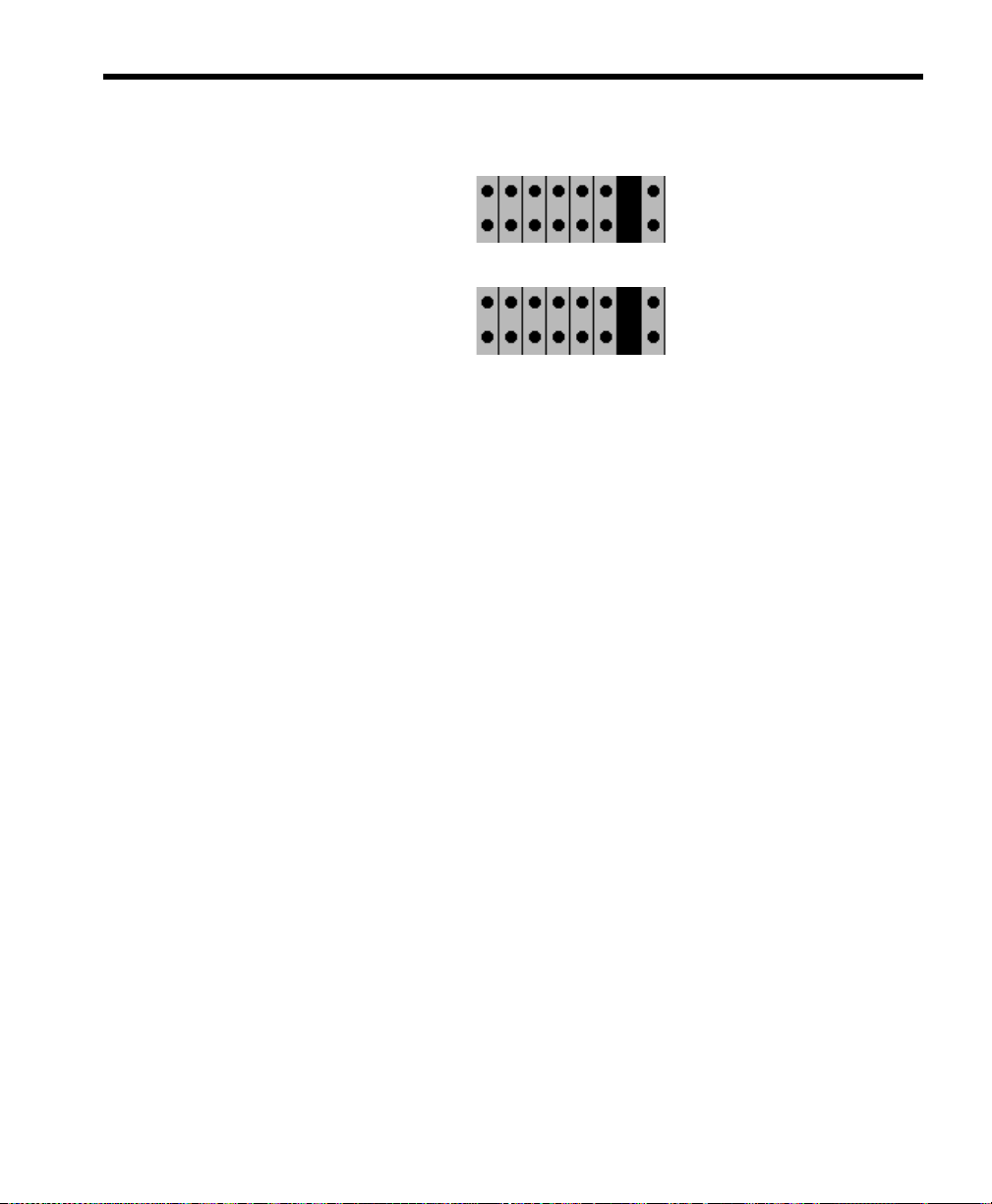
Closed means that two pins are covered/connected by the shorting jumper,
and Open means that the two pins are not covered/ conn ected b y the shorting
jumper. In the diagrams in this chapter, the blacked out pin positions
represent closed positions.
IP
T
: Installers often place shorting jumpers over only one pin
when the position is Open. This does not connect the pins,
but it does prevent losing jumpers.
Notice that the jumper positions numbered 3 through 7 are always closed
and that the jumper positions numbered 8 and 9 are always open. You will
change only the leftmost three jumper positions (those numbered 0, 1, and 2
in the table).
Page 22

10 Installing Amanda@Work.Group/DOS
The next table show the jumper positions graphically.
A Graphical View
Board
1
2
3
4
5
Hex
Address
300
301
302
303
304
Jumper Positions
AUTION
C
6
305
: Do not add or remove shorting jumpers while power is ap-
plied to the board.
Page 23

Chapter 2: Installing RDSP/x32 Boards 11
ShowJump Utility
Brooktrout provides the ShowJump utility which also shows how to
configure the jumpers on various types of Brooktrout boards. On Amanda,
this utility is stored in the C:\PLATFORM directory.
To use ShowJump:
1. At a DOS prompt, type:
C:\PLATFORM\SHOWJUMP
The Brooktrout Board Jumper Configuration Utility Screen displays the
jumper configuration for hex address 300 on boards 2108 a nd 4108
(which Amanda does not support).
2. Press Page Down until the board you are interested in is displayed.
3. Then type the hex address and press Enter.
The jumper configuration for the displayed board changes to fit the
address that you entered.
4. Press Esc to exit.
Installing Voice Boards
After making sure the address for the voice board is correct, you can install
it.
To install the voice board:
1. If this is a new installation, go to step 2. Otherwise, shut down Amanda
and turn off the computer:
a. Press Alt+S (if Amanda is running as a standalone) or s (if
Amanda is running as a voice server).
b. Type in the p assword. (The default is A MandA with only the
first two and the last letter capitalized.)
c. Press Enter.
Page 24

12 Installing Amanda@Work.Group/DOS
d. Press Y (to confirm the shutdown).
e. Press Y again (to reconfirm).
f. A fter the DOS prompt C:\AMANDA> appears, turn off the
power.
2. Remove the computer cover and locate an available slot. A full length
slot is needed for models 2132 and 4132.
3. Remove the back slot cover and install the voice board. If there is a rear
card guide, slide the end of the voice board into it properly.
4. Close the computer cover and turn on the power.
AUTION
C
: Use an ESD-safe station while configuring and install-
ing your board. Otherwise, static discharge may damage your board. (ESD stands for electrostatic
discharge.)
Connecting Ports
You create a port by connecting a telephone line to a voice board. Amanda
can support from 2 to 24 ports. On a Brooktrout voice board with two
connectors, the top connector represents the first two ports and the bottom
connector represents the second two ports for a total of four ports per board.
Each connector on a voice board is an RJ-14 modular jack. The inner pair is
one port, and the outer pair is the other port.
Page 25

Chapter 2: Installing RDSP/x32 Boards 13
Ports are numbered consecutively from 1 to 24. Port 1 is connected to the
lowest addressed voice board (usually address 300). Each connector on the
voice board is linked to your telephone switching system by a standard 4wire line cord to a standard RJ-14 modular jack which should represent two
analog (single-line) extensions.
Page 26

14 Installing Amanda@Work.Group/DOS
COM1
COM2
VGA Card
Modem
The above diagram shows the back of Amanda.
Voice Ports
432
1/2
3/4
Page 27

Chapter 2: Installing RDSP/x32 Boards 15
Voice Ports
1 & 2
Voice Ports
3 & 4
Telephone
Phone Switch
tline-R.cad
The above diagram shows how the telephones, telephone switching system,
and Amanda are connected.
Page 28

16 Installing Amanda@Work.Group/DOS
Page 29

Chapter 3: Installing RDSP/RTNI Boards
Installation Checklist
The RDSP/RTNI two-board combination puts all the Digital Signal
Processors (DSPs, specialized CPUs) on one board and provides an analog
telephony interface with the other.
You must configure and install each of the following:
• An RDSP/x000 (that is RDSP/4000, RDSP/8000, RDSP/12000,
RDSP/16000, RDSP/24000) board that provides the DSPs.
• An RTNI-xATI (that is RTNI-4ATI, RTNI-8ATI, RTNI-12ATI,
RTNI-16ATI, RTNI-24ATI) bo ard that provides an analog telephony interface.
You must connect the interface board to the RDSP/x000 board using the
MVIP bus cable, which will transfer voice data between the two boards. The
connector cable for this is supplied with the board set. Since the RDSP/x000
board does not provide its own clock, it also receives timing information
from the bus.
In addition, you must connect the RTNI board to the telephone network.
Follow this checklist or use it to verify that you have completed all the
necessary steps for connecting Amanda to the telephone switching system.
Page 30

18 Installing Amanda@Work.Group/DOS
OTE
N
: The GetTones and AccuCall Plus utilities cannot define
dial codes while the RDSP/RTNI two-board combination is
installed. The utilities do not know how to make MVIP
connections to the DSP resource in order to dial. The only
solution is to use a 232 or 432 voice board while you define
the tones. Then you replace the 232 or 432 voice board with
the ATI board combination.
Be sure to…
1. Configure an RDSP/x000 board:
a. Configure MVIP Streams
b. Configure the MVIP Termination
c. Configure the Base I/O Port
2. Configure an RTNI-xATI boa rd:
a. Configure the MVIP Termination
b. Configure the Base I/O Port
c. Configure the Line Interface
3. Configure an RTNI-2T1 board:
a. Configure the Base I/O Port
b. Configure the IRQ Jumpers
c. Configure the Line Interface
4. Install the boards
5. Install the MVIP cable
6. Install Amanda software without errors
7. Connect the line cords from the voice boards to the telephone switching
system
8. Test each voice board port for answering
9. Run Setup to define dial codes
10. Program the telephone switching system for voice mail integration
Page 31

Chapter 3: Installing RDSP/RTNI Boards 19
11. Run Setup to obtain tone patterns
12. Run Setup to define telephone switching system integration patterns
13. Run Setup to define Amanda system configuration options
Requirements
Before installing the RDSP/x000 board, verify that the host system meets
each of the following requirements:
• Bus speed is 8 MHz with 0 wait states or 10 MHz with 1 wait state
• Can provide +5v 3.0 A power to the RDSP/x000 board
These requirements are in addition to those for the system.
Configuring an RDSP/x000 Voice Board
The following figure shows the locations of the jumper blocks and
connectors on the RDSP/x000 board. The tables below it describe those
jumper blocks and connectors and show how to jumper the RDSP/x000
board for use with Amanda.
Later sections of this chapter offer more detailed explanations about how to
jumper this board.
Page 32

20 Installing Amanda@Work.Group/DOS
The RDSP/x000 Board
W3
W1
W2
2
J2
1
W4
40
39
Jumper Block and Connector Information
Table 1: Jumper Positions for Use with Amanda
Label Type Description 1 2 3 4 5 6 7 8
W1 Jumper
block
DSi MVIP
stream
Open Open Open Open Open Open Closed Open
W2 Jumper
block
W3 Jumper
block
W4 Jumper
block
DSo MVIP
stream
Base I/O
port
MVIP termination
J2 Connector MVIP bus
Closed means that two pins are covered/connected by the shorting jumper,
and Open means that the two pins are not covered/connected by the shortin g
Open Open Open Open Open Open Closed Open
Closed Closed Closed Closed Closed Open Open
Closed Closed
Page 33

Chapter 3: Installing RDSP/RTNI Boards 21
jumper. In the diagrams in this chapter, the blacked out pin positions
represent closed positions.
IP
T
: Installers often place shorting jumpers over only one pin
when the position is Open. This does not connect the pins,
but it does prevent losing jumpers.
W1
W4
W2
W3
Understanding MVIP Streams
MVIP is a standard protocol for connecting PC resources. The MVIP bus
provides both physical and l ogical hal f-dup lex internal connecti ons for u p to
512 resources.
The MVIP bus is segmented into 8 bidirectional serial data streams, each
composed of a pair of unidirectional streams. Each unidirectional stream can
carry 2.048 megabits of data per second, partitioned by Time Division
Multiplexing into 32 64-kilobits-per-second (Kb/sec.) time slots. A single
MVIP time slot has sufficient bandwidth to do either of the following:
• Carry PCM voice data
• Be a 64 Kb/sec. pipe for data communications
Numbering schemes for both streams and time slots start with 0. An MVI P
board is configured to use one of the eight streams on the bus. The port
associated with each time slot is made up of two half-duplex connections.
Page 34

22 Installing Amanda@Work.Group/DOS
During configuration, each resource on the board is mapped to a discrete
time slot of the stream.
For example, the stream on an RDSP/24000 board automatically maps time
slots 1, 9, 17, and 25 to RDSP resources to 1, 2, 3, and 4, respectively. The
port associated with Time Slot 4 has two halves: the input designated DSi4,
and the output DSo4. The network interface board is the point of reference
for input and output.
Configuring MVIP Streams
Each RDSP/x000 board uses two MVIP streams: one for receiving and one
for transmitting. The RDSP/x000 board can receive on one of the DSi
streams (DSi0 through DSi7) and can transmit on one of the DSo streams
(DSo0 through DSo7). Each RDSP/x000 board is factory-configured to use
streams DSi6 and DSo6. The Amanda Company recommends that you keep
these settings.
The DSi stream jumper block consists of a pin position for each DSi stream.
If you look at the board with the bracket on your right, the leftmost pin
position corresponds to DS i0, the nex t pin pos ition cor respon ds to DSi1, and
so on. The rightmost pin position corresponds to DSi7.
The DSo stream jumper block has the same construction as the DSi stream
jumper block with the leftmost pin position corresponding to DSo0 and the
rightmost pin position corresponding to DSo7.
To configure the DSi and DSo streams:
1. Find the jumper block for the DSi and DSo streams on the board.
The jumper block for the DSi MVIP stream is labeled W1. It is below
the MVIP connector if the bracket is to your right.
The jumper block for the DSo MVIP stream is labeled W2. It is below
the MVIP connector and the W1 block if the bracket is to your right.
Page 35
Chapter 3: Installing RDSP/RTNI Boards 23
2. The settings should be as shown below:
W1
W2
3. Only the second to last pin position should be closed with a shorting
jumper.
AUTION
C
: Do not add or remove shorting jumper s while power is
applied to the board.
Configuring the MVIP Termination
Each RDSP/x000 can terminate the C2 MVIP and C4 MVIP bus signals. In a
series of boards that are on an MVIP bus, the boards at both ends must
terminate C2 and C4 while the other boards must not terminate the signals.
For example, the following figure shows three boards on an MVIP bus. The
left and right boards must terminate the MVIP bus signals while the middle
board must not. Each RDSP/x000 is configured at the factory to terminate
both C2 and C4.
Page 36

24 Installing Amanda@Work.Group/DOS
The MVIP termination block consists of two pin positions, one for the C2
and one for the C4. If you look at the board with the bracket on your right,
the pin position on the left corresponds to C4 and the pin position on the right
corresponds to C2. The Amanda Company assumes that you are installing
only one RDSP/x000 board and, therefore, that it should terminate both
signals.
To terminate both MVIP bus signals:
1. Find the MVIP termination block on the board.
It is labeled W4 and is below the MVIP connector at the right of the W1
block if the bracket is to your right.
2. For use with Amanda, close both signals’ pin positions using shorting
jumpers (as shown below).
W4
AUTION
C
: Do not add or remove shorting jumpers while power is
applied to the board.
Page 37

Chapter 3: Installing RDSP/RTNI Boards 25
Configuring the Base I/O Port
Each RDSP/x000 uses 47 I/O ports in addition to its base I/O port. Seven o f
these additional I/O ports are contiguous to the base I/O port. For examp le, if
the RDSP/x000’s base I/O port is 300H, then the seve n con tig uou s I/ O ports
are 301H, 302H, 303H, 304H, 305H, 306H and 30 7H . The RDSP /x0 00 al so
uses five additional I/O ports offset from the base I/O port and each of its
seven contiguous I/O ports:
• I/O port plus 400H
• I/O port plus 800H
• I/O port plus C00H
• I/O port plus 1000H
• I/O port plus FC00H
Each RDSP/x000 board is factory-configured to use base I/O port 300H. If
you are installing more than one RDSP/x000 board, you need to change the
base I/O ports so that each board has a unique base I/O port. If you are
installing only one RDSP/x000 board, you need to change its base I/O port
only if there is an I/O port conflict with another device.
Each RDSP/x000 must use a base I/O port in the range 0000H through
3FFH. The Amanda Company assumes that you are installing only one
RDSP board and recommends that you use base I/O port 300H.
To configure the base I/O port:
1. Find the jumper block for the base I/O port.
It is labeled W3 and is below the W2 block if the bracket is to your
right.
2. Set W3 for use with Amanda as shown below.
Close the five positions on the left using shorting jumpers and open the
two positions on the right.
W3
Page 38

26 Installing Amanda@Work.Group/DOS
Hex Jumper positions
Row Address 0 1 2 3 4 5 6
1
300 Closed Closed Closed Closed Closed Open Open
AUTION
C
: Do not add or remove shorting jumpers while power is
applied to the board.
Configuring an RTNI-xATI Voice Board
An RTNI-xATI board’s main function is connecting any line resource with
any other line or MVIP resource. This is commonly called switching. Your
RTNI-xATI board provides Analog-to-MVIP switching. The line r esource
for your ATI board is analog, but only digital PCM signals can be switched,
so the board must convert the incoming analog signal to PCM prior to
switching. This conversion is made by the board’s loop start module which
links the MVIP bus and a trunk line. Amanda uses only the linki ng function
and not the switching function of MVIP.
The following figure shows the locations of the jumper blocks and
connectors on the RTNI-xATI board. The tables below it describe those
jumper blocks and connectors. They also show how to jumper the RTNIxATI board for use with Amanda.
Page 39

Chapter 3: Installing RDSP/RTNI Boards 27
Jumper
Label Type Description
Settings
Jumpers
Connectors
EJ10 Jumper block Base I/O Address Open
Open
Closed
Closed
Closed
Closed
Open
Closed
Closed
Closed
W1 Jumper block MVIP Termination Closed
W2 Jumper block MVIP Termination Closed
J1 Connector MVIP bus
J4 Connector Telephony Cable
Closed means that two pins are covered/connected by the shorting jumper,
and Open means that the two pins are not covered/ conn ected b y the shorting
jumper.
EJ10 W1
W2
Page 40

28 Installing Amanda@Work.Group/DOS
Configuring the MVIP Termination
The MVIP termination block consists of two pin positions, one for the C2
and one for the C4. The top pin position (lab eled W1) corresponds to C4 and
the next pin position (labeled W2) corresponds to C2.
You should close both pin positions. The Amanda Company assume s that
you are inst alling only one RTNI-xATI board along with an RDSP/x000
board. In this case, this board should terminate both signals.
To terminate both MVIP bus signals:
1. Find the MVIP termination block on the board.
One pin position is labeled W1 and the other is labeled W2. They are
located just below the J1 connector with the bracket on your right.
2. For use with Amanda, close both signals’ pin positions using shorting
jumpers (as shown below).
W1
W2
AUTION
C
: Do not add or remove sh orting jumpers w hile power is
applied to the board.
Configuring the Base I/O Port
Each voice board must have a unique base I/O port. Each RTNI-xATI board
is factory-configured to use base I/O p ort 308 H. It us es the b ase I/O p ort an d
three others, calculated as offsets of the base I/O port. These I/O ports are:
• Base I/O port
• Base I/O port plus 400H
• Base I/O port plus 800H
• Base I/O port plus C00H
Page 41

Chapter 3: Installing RDSP/RTNI Boards 29
For example, if the RTNI-xATI board’s base I/O port is 308H, then the ATI
board uses the following I/O ports:
• 308H
• 708H
•A08H
•E08H
If you are installing only one RTNI-xATI board, you must change its base I/
O port only if another device in the computer has the same I/O port. The
Amanda Company recommends that you use 308H.
To set the base I/O port:
1. Locate the base I/O port jumper block.
It is labeled EJ10.
2. For use with Amanda, set the jumpers as shown below.
EJ10
AUTION
C
: Do not add or remove shorting jumpers while power is
applied to the board.
Configuring the Line Interface
The line interface configuration of your R TNI-xATI board determines which
CO provisions it requires. You must match the line connection to you r line
interface module configuration as follows:
Page 42

30 Installing Amanda@Work.Group/DOS
Interface Type: 2-Wire Loop Start
USOC Jack Connector: RJ21X
REN/Service Code: X.XB
Facility Interface Code: 02LS2
The Loop Start module links your MVIP bus and a telep ho ne lin e from you r
CO or PBX. For a loop start, you alert your CO to an outbound call by
connecting the tip to the ring, thereby closing the loop and allowing current
to flow.
Physical Connections
After you have installed the board (as explained in “Installing the Boards” on
page 32), use the cable supplied with the RTNI-xATI board to connect the
Amanda system to the telephone network. Connect the 62-pin connector to
the RTNI-xATI board and the Amphenol 50-pin connector to a 66 Block.
Pinout Table for Amphenol 50-pin Connector
Pin Description-Color code Pin Description-Color code
26 T1: Channel 1 Tip-white/blue 13 R13: Channel 13 Ring-green/black
1 R1: Channel 1 Ring-blue/white 39 T14: Channel 14 Tip-black/brown
27 T2: Channel 2 Tip-white/orange 14 R14: Channel 14 Ring-brown/black
2 R2: Channel 2 Ring-orange/white 40 T15: Channel 15 Tip-black/gray
28 T3: Channel 3 Tip-white/green 15 R15: Channel 15 Ring-gray/black
3 R3: Channel 3 Ring-green/white 41 T16: Channel 16 Tip-blue/yellow
29 T4: Channel 4 Tip-white/brown 16 R16: Channel 16 Ring-yellow/blue
4 R4: Channel 4 Ring-brown/white 42 T17: Channel 17 Tip-yellow/orange
30 T5: Channel 5 Tip-white/gray 17 R17: Channe l 17 Ring-ora nge/yellow
Page 43

Chapter 3: Installing RDSP/RTNI Boards 31
Pinout Table for Amphenol 50-pin Connector (Con-
Pin Description-Color code Pin Description-Color code
5 R5: Channel 5 Ring-gray/white 43 T18: Channel 18 Tip-yellow/green
31 T6: Channel 6 Tip-red/blue 18 R18: Channel 18 Ring-green/yellow
6 R6: Channel 6 Ring-blue/red 44 T19: Channel 19 Tip-yellow/brown
32 T7: Channel 7 Tip-red/orange 19 R19: Channel 19 Ring-brown/yellow
7 R7: Channel 7 Ring-orange/red 45 T20: Channel 20 Tip-yellow/gray
33 T8: Channel 8 Tip-red/green 20 R20: Channel 20 Ring-gray/yellow
8 R8: Channel 8 Ring-green/red 46 T21: Channel 21 Tip-violet/blue
34 T9: Channel 9 Tip-red/brown 21 R21: Channel 21 Ring-blue/violet
9 R9: Channel 9 Ring-brown/red 47 T22: Channel 22 Tip-violet/orange
35 T10: Channel 10 Tip-red/gray 22 R22: Channel 22 Ring-orange/violet
10 R10: Channel 10 Ring-gray/red 48 T23: Channel 23 Tip-violet/green
36 T11: Channel 11 Tip-black/blue 23 R23: Channel 23 Ring-green/violet
11 R11: Channel 11 Ring-blue/black 49 T24: Channel 24 Tip-violet/brown
37 T12: Channel 12 Tip-black/orange 24 R24: Channel 24 Ring-brown/violet
12 R12: Channel 12 Ring-orange/ black 50 Analog Ground-violet/gray
38 T13: Channel 13 Tip-black/ green 25 BAT-: Negative battery terminal-gray/ violet
ShowJump Utility
Brooktrout provides the ShowJump utility which also shows how to
configure the jumpers on various types of Brooktrout boards. On Amanda,
this utility is stored in the C:\PLATFORM directory.
Page 44

32 Installing Amanda@Work.Group/DOS
To use ShowJump:
1. At a DOS prompt, type:
C:\PLATFORM\SHOWJUMP
The Brooktrout Board Jumper Configuration Utility Screen displays the
jumper configuration for hex address 300 on boards 2108 and 4108.
2. Press Down Page until the board you are interested in is displayed.
3. Then type the hex address and press Enter.
The jumper configuration for the displayed board changes to fit the
address that you entered.
4. Press Esc to exit.
Installing the Boards
Use the following procedure to install one or more RDSP/RTNI boards.
To install the board:
1. If this is a new installation, go to step 2. Otherwise, shut down Amanda
and turn off the computer:
a. Press Alt+S (if Amanda is running as a standalone) or s (if
Amanda is running as a voice server).
b. Type in the password. (The default is AMandA with only the
first two and the last letter capitalized.)
c. Press Enter.
d. Press Y (to confirm the shutdown).
e. Press Y again (to reconfirm).
f. A fter the DOS prompt C:\AMANDA> appears, turn off the
power.
2. Remove the cover.
3. Locate free bus slots that have 16-bit-compatible, ISA bus edge connectors.
Page 45

Chapter 3: Installing RDSP/RTNI Boards 33
4. Carefully align the boards with the slot and firmly seat the boards into
the computer .
5. Use a bracket screw to securely fasten the boards’ brackets.
The bracket provides grounding for the board.
6. Turn the computer back on.
7. From the C:> DOS prompt, follow the installation instructions in
“Chapter 5: Installing Amanda Software.”
AUTION
C
: Use an ESD-safe station while configuring and install-
ing your board. Otherwise, static discharge may damage your board.
Installing the MVIP Cable
After installing an RDSP/x000 board you need to connect the MVIP bus
cable to each board.
This 40-pin MVIP-compliant connector is at the top of the b oard if yo u loo k
at the board with the bracket to your right. Use the MVIP connector to
connect the RDSP/x000 board to a telephone network interface board.
If your MVIP connector cable has more than two connector positions, use
the two end-positions for this installation.
Configuring Amanda to Use the ATI Board
There are a couple of Amanda’s configuration options that must be set
correctly when you are using an RTNI-xATI voice board. See “Running
Setup” on page 49 for information about using the Setup utility to set or
check these advanced configuration options.
The configuration optio n ati_mode must be set to true. Then Amanda makes
the connections needed for the ATI board.
Page 46

34 Installing Amanda@Work.Group/DOS
Be aware that RTNI-xATI voice boards cannot detect rotary. If you use an
RTNI-xATI voice board, you must leave the rotary configuration option set
to false.
Page 47

Chapter 4: Other Cards and Devices
Installing a LAN Card
To use Amanda as a voice server, you must install a LAN card, also called a
network interface card (NIC). The card must be NE2000 compatible.
If you have any problems with the installation and you purchased the NIC
from The Amanda Company, please contact Customer Service.
To install a LAN card:
1. Configure the card.
If you purchased your LAN card from The Amanda Company, it is pre-
configured for IRQ 10, I/O address 340H, and is to be used with
unshielded twisted pair (UTP) cable. These are the default settings.
If you purchase another LAN card, use this IRQ and address. Follow
that LAN card’s instructions for installation.
OTE
N
: Addresses 300 through 305 are not available for the LAN
card. See “Chapter 2: Installing RDSP/x32 Boards” and
“Chapter 3: Installing RDSP/RTNI Boards” for more information.
2. If this is a new installation, go to step 3. Otherwise, shut down Amanda
and turn off the computer:
a. Press Alt+S (if Amanda is running as a standalone) or s (if
Amanda is running as a voice server).
Page 48

36 Installing Amanda@Work.Group/DOS
b. Type in the password. (The default is AMandA with only the
first two and the last letter capitalized.)
c. Press Enter.
d. Press Y (to confirm the shutdown).
e. Press Y again (to reconfirm).
f. A fter the DOS prompt C:\AMANDA> appears, turn off the
power.
3. Remove the computer cover and locate an available slot.
4. Remove the back slot cover and install the LAN card. If there is a rear
card guide, slide the end of the LAN card into it properly.
AUTION
C
5. Connect the LAN card to the rest of the network.
: When installing your LAN card, you must be careful
about electrostatic discharges (ESD). Use an ESD-safe
environment, a wrist guard, and s o on. Otherwise, s tatic discharge may damage your card.
The Amanda Voice Server sends an d receives NetBEUI commands, and
can be part of any network that supports NetBIOS over NetBEUI.
6. Reassemble the computer and restart it by turning the power switch on.
Using a UPS
The Amanda Company strongly recommends the installation of an
uninterrupted power supply (UPS) with every Amanda system. It provides
clean power to Amanda and keeps the pr obab ility of a computer lockup (and
the resulting loss of data or even loss of the system) as low as possible.
According to some reports, power problems are the primary reason why
computers lose data (45.3%). The next closest cause is storm damage at
9.4%. (Human error and sabotage rank eighth with 3.2%.)
Page 49

Chapter 4: Other Cards and Devices 37
According to a Bell Laboratories study entitled “The Quality of US
Commercial AC Power,” the main categories of AC power irregularities
across the nation are sags (or brownouts), power surges, blackouts, and
overvoltages. The best solution is a UPS, which can handle 99.3% of these
power problems.
A UPS is a special type of AC power line conditioner. When compared to
the other devices available, such as surge suppressors, filters, isolation
transformers, tap changing regulators, and voltage regulating transformers,
the UPS is rated highest by Bell Laboratories and is relatively inexpensive.
The cost of installing a UPS is nominal when compared to the cost of
repairing a damaged Amanda system or compared to the loss of confidence
from callers and internal Amanda users.
For more information about what causes power irregularities and what
damage they can do to Amanda, call to be faxed Technical Note 10, “The
Importance of a UPS.”
Page 50

38 Installing Amanda@Work.Group/DOS
Page 51

Chapter 5: Installing Amanda Software
Running the Installation Program
Install Amanda software only after you have:
• Installed the voice boards.
• (Voice server only) In stalled an NE2 000-comp atible Ethernet LAN
card.
Follow the installation checklist that is in the chapter that explains how to
configure the voice boards you use:
• “Chapter 2: Installing RDSP/x32 Boards”
• “Chapter 3: Installing RDSP/RTNI Boards”
If you are installing Amanda as a voice server, have your MS Workgroup
Add-on for DOS disk at hand.
To start the Amanda installation program:
1. Insert the disk labeled “Amanda@Work.Group/DOS, Installation Disk 1
of 5” into a floppy disk drive.
2. From the DOS prompt C:\>, type the command:
A:\INSTALL
(If the disk is in drive B:, use B:\INSTALL B:.)
Then press Enter.
Page 52

40 Installing Amanda@Work.Group/DOS
You see a screen similar to the following:
Correct operation of an Amanda Call Processing system depends on accurate
time and date settings in the computer. To assure correct operation,
please verify these now. Here are the present time and date:
Current time is 3:13:04.99p
Current date is Tue 01-14-1997
Are these values correct[N,Y]?
3. Type Y for Yes or N for No.
If you type Y, proceed to step 4.
If you type N, you are p rompt ed for a new dat e and t ime, si milar to what
is shown below.
a. Type a new date then press Enter or just press Enter to keep the
current date.
b. Type a new time then press Enter or just press Enter to keep the
current time.
Please correct the Time and/or Date now.
Current date is Tue 01-14-1997
Enter new date (mm-dd-yy): 01-14-97
Current time is 3:14:36.11p
Enter new time:
Page 53

Chapter 5: Installing Amanda Software 41
Information similar to the following appears on the screen.
This program installs or un-installs Amanda@Work.Group/DOS
Version 7.xx Revision X on your computer system.
You may press the [Esc] key at any time to stop
the installation.
PLEASE NOTE: This installation stores backup copies of any files
that it overwrites on your hard disk. If after
installing you wish to revert to your previous
system, run this install program again and select
the "Un-install ..." option.
Press [Esc] to quit, any other key to continue ...
4. Press any key on the keyboard to continue.
An installation, reinstallation, or an update menu appears.
INSTALLATION MENU
Select the type of installation that you want to be performed.
Use the arrow keys to make a selection; then press Enter.
Install Amanda@Work.Group/DOS Version 7.xx Revision X
Test the configuration of this system only
Exit this installation program now
Page 54

42 Installing Amanda@Work.Group/DOS
REINSTALLATION MENU
Amanda@Work.Group/DOS Version 7.xx Revision X is already
installed on this machine.
Select the action that you want to be performed.
Use the arrow keys to make a selection; then press Enter.
Re-install Amanda@Work.Group/DOS Version 7.xx Revision X
Un-install the existing Amanda@Work.Group/DOS 7.xx Revision X system
Test configuration of this machine only
Exit this installation program now
UPDATE MENU
Amanda@Work.Group/DOS Version 7.xx Revision X using RH-RDSP
style boards appears to be installed on this machine.
Select the type of installation that you want to be performed.
Use the arrow keys to make a selection; then press Enter.
Update existing Amanda@Work.Group/DOS 7.xx Rev. X
Test configuration of this machine only
Exit this installation program now
5. In any case, select the first option on the menu then press Enter.
If this is a new installation, go to step 6. Otherwise, go to step 7.
Page 55

Chapter 5: Installing Amanda Software 43
6. You see a screen similar to the following:
Since this a first time installation, Amanda@Work.Group/DOS needs to know
if this system uses Brooktrout RDSP/x32 or RDSP/x000 with RTNI-xATI
style boards. Make this choice very carefully since this choice is
PERMANENT!
Select the Brooktrout board type for this installation from the list.
Use the arrow keys to make a selection; then press Enter.
Brooktrout RDSP/x32 style two or four port boards
Brooktrout RDSP/x000 with RTNI-xATI style boards
I am not sure; stop so I can find out first
Use the arrow keys to select the appropriate style of Brooktrout voice
board then press Enter.
7. The next screen asks wh ether you are ins talling Amanda as a standalone
system or as a voice server.
Page 56

44 Installing Amanda@Work.Group/DOS
Amanda@Work.Group/DOS can be installed as a networked Voice Server,
integrated with a local area network (LAN), or as a stand-alone system.
If you elect the Voice Server installation, you must have a properly set
NE2000 compatible Ethernet LAN adaptor installed in this machine prior to
installing this software.
[If you install the LAN adaptor, it MUST be set for IRQ 10 and I/O
address 340, AND you MUST have your MS WORKGROUP ADD-ON FOR DOS disk]
Select the type of configuration that you want to be performed.
Use the arrow keys to make a selection; then press Enter.
No LAN card. Configure Stand-alone system.
The LAN card is installed. Configure Voice Server system.
Exit. I need to install the LAN card first.
If you plan to use Amanda client software to configure Amanda and
allow users to access messages from their computers as well as their
telephones, you need to install Amanda as a voice server, select the second option “The LAN card is installed. Configure Voice Server system. ”
If you plan to configure Amanda from this computer and allow users to
access messages only from their telephones, select the first option “No
LAN card. Configure Stand-alone system.”
8. The next few screens display information about your computer and the
installation. Follow the directions on the screen.
If everything is OK, the installation can continue. Otherwise, the installation stop s.
The first screen of the following examp les appear s only fo r n ew ins tallations. If you are installing Amanda as a standa lone system, some scr eens
will have less information than the examples.
Page 57

Chapter 5: Installing Amanda Software 45
Since this is a new installation, a new CONFIG.SYS file will be
created; you do not need to take any action yourself.
Press [Esc] to quit, any other key to continue ...
Checking your computer for the proper components and conflicts .
. .
Verifying computer processor type . . . OK
Verifying the video adaptor type . . . . OK
Verifying total amount of memory . . . . OK
Verifying total conventional memory. . . OK
Verifying operating system version . . . OK
Verifying sufficient free disk space . . OK
Press [Esc] to quit, any other key to continue ...
Page 58

46 Installing Amanda@Work.Group/DOS
Please note that you have the following additional components . . .
Serial port COM1 at address : 1016
Serial port COM2 at address : 760
Serial port COM3 at address : 744
Parallel port LPT1 at address: 888
Video Adaptor Card type : VGA (Video Graphics Array)
Video Monitor Display type : Color
Available disk space : 176295936
Press [Esc] to quit, any other key to continue ...
Your original installation of Amanda@Work.Group/DOS 7.xx Revision X
is nearly finished.
The system will next reboot and the initial memory configuration
will begin.
Next, the network portion of the Voice Server will be installed.
Finally, since this is a new installation, the SETUP program will
run automatically to create a configuration file with all default
values for you. Last, the system will reboot again and Amanda
will be started.
REMOVE INSTALLATION "DISK 5 of 5" FROM DISK DRIVE.
Press any key to continue ...
If the installation proceeds, you will be asked to insert each of the five
installation disks into your floppy disk drive in order.
Page 59

Chapter 5: Installing Amanda Software 47
If you selected a networked Voice Server installation, you will also be
asked to install the MS-NETWORK files required to connect your
Amanda@Work.Group/DOS Voice Server to the network. You will be
asked to remove the disk labeled “Microsoft Workgroup Add-On for
MS-DOS, Disk 1 - Setup” from its sealed envelope and insert it in your
floppy disk drive.
Opening the sealed envelope indicates your acceptance of the Micr osoft
software license terms shown on the inside cover of the User’s Guide
for Microsoft WORKGROUP ADD-ON MS-DOS included in your package.
During the installation process, your computer will reboot once or
twice.
9. Follow the directions on the screens. Eventually, a screen informs you
that “This completes the installation….”
OTE
N
: If this is an upgrade or a reinstallation, the installation pro-
gram does not update your existing CONFIG.SYS file.
However, it suggests that you change your CONFIG.SYS
to work better with Amanda.
It recommends that you reset the DOS environment memory size to an amount ba sed on the inf ormation yo u provi ded about ports during the installation.
For example, if the pro gram s ugg est s a setting of 346, you
should add or change the /E parameter in your SHELL
statement. It might look like the following:
SHELL=C:\COMMAND.COM /E:346 /P
The installation program also suggests that you remove the
EMS memory limit allocated for your m emory manager (if
that manager is EMM386.EXE).
For example, suppose the DEVICE statement for
EMM386.EXE is similar to the following:
DEVICE=C:\DOS\EMM386.EXE 272 …
You remove the 272. The EMS memory limit is the only
solitary number in the DEVICE statement.
10. Set up Amanda to work with your telephone switching system and
according to your voice mail preferences.
Use the next few chapters to define dial codes, define tone and integration patterns, and set Amanda’s configuration options.
Page 60

48 Installing Amanda@Work.Group/DOS
Updating Amanda
If you are upgrading Amand a software, the ins tallation screens are somewhat
different from the new installation described above. Follow the directions on
the screen, and the installation process should go smoothly.
If the installation program recommends changes to your CONFIG.SYS file,
you need to make these changes yourself. The installation program does
NOT create a new CONFIG.SYS file for you because commands you added
or changed to run your system could be replaced.
If you installed Amanda as a standalone only, change C:\CONFIG.SYS, the
CONFIG.SYS file in the root directory.
If you installed Amanda as a voice server, make the recommended changes
to both C:\AMANDA\DOSMODE\CONFIG.SYS and
C:\AMANDA\NETMODE\CONFIG.SYS. Depending on the mode in which
you run Amanda, the CONFIG.SYS file (and other files) are copied to the
root directory (C:\) from either C:\AMANDA\DOSMODE or
C:\AMANDA\NETMODE. Changing the CONFIG.SYS in the root
directory only is like not changing the file at all because it will be replaced
every time you start Amanda.
Page 61

Chapter 6: Running the Setup Utility
Running Setup
You must configure Amanda to work properly with your telephone
switching system and to let Amanda know your customer’s voice mail and
other preferences. The Amanda Company provides the Setup utility to make
configuring Amanda easier.
You run Setup to configure dial codes, tone patterns, DTMF integration
patterns, and Amanda’s system configuration options.
To run Setup:
1. If Amanda i s running, shut down t he Amanda s ystem.
a. Press Alt+S (if Amanda is running as a standalone) or s (if
Amanda is running as a voice server).
b. Type in the p assword. (The default is A MandA with only the
first two and the last letter capitalized.)
c. Press Enter.
d. Press Y (to confirm the shutdown).
e. Press Y again (to reconfirm).
2. Change to the AMANDA directory—unless you are there already. At
the DOS prompt , type:
CD C:\AMANDA
Then press Enter.
Page 62

50 Installing Amanda@Work.Group/DOS
3. Now that the DOS prompt reads C:\AMANDA, type:
SETUP
Then press Enter.
The Amanda@Work. Grou p/D OS Configuration Utility menu appears.
4. From this menu, you define the following for your telephone switching
system and Amanda. Each is described in one of the next few chapters:
• Telephone System Dial Codes
• Telephone System Tone Patterns
• System Integration Patterns
• System Configuration Options
System Co nfiguration Options contains two sections:
General Configuration Displays dialog boxes that guide you through
the options that are most often changed, whether they appear in the INSTALL.CFG file or the
default template for mailboxes (normally mailbox 997).
These dialog boxes are explained in “Chapter
10: Configuring Amanda.”
Advanced Configuration Allows you to change any configuration s etting
in INSTALL.CFG. The options are divided
into categories to make it easier to locate the
options you need to change. The options are parameter lists. Each option is explained in
“Chapter 18: Configuration Reference.”
Page 63

Chapter 7: Defining Dial Codes
Defining Dial Codes
To communicate with the telephone switching system, Amanda must know
the switching system’s dial codes. Most Amanda systems are connected to
only one switching system, but you can connect your system to two.
By default, the 1001.PBX file is used to store dial codes. You can change
this if you choose. However The Amanda Company has reserved the
numeric names from 1002 to 200 1, so do not us e any number in t hat range as
the name of your file.
As part of a new installation, the file 1001.PBX is created for you based on
the Panasonic KX-T308/616/1232 telephone switching system. If you are
upgrading your Amanda system, the file you used for dial codes in the past
will be renamed to 1001 (and 2001 if two switches are used). Also, the Setup
utility may not know what switching system your dial codes file is based on.
The names of the switching systems appear in the .PBX files containing
codes for these systems and are displayed by the Setup utility. Yours may be
based on an older versi on of Amanda that did not have the switching system
names in the files. If so, yours may be identified by Setup as “not defin ed.”
OTE
N
: Instead of using Setup, you can edit your .PBX file in the
C:\AMANDA\PBX.DB directory using the JOVE utility.
See “Chapter 12: Utilities,” in Administering Aman-
da@Work.Group/DOS for information about JOVE.
Page 64
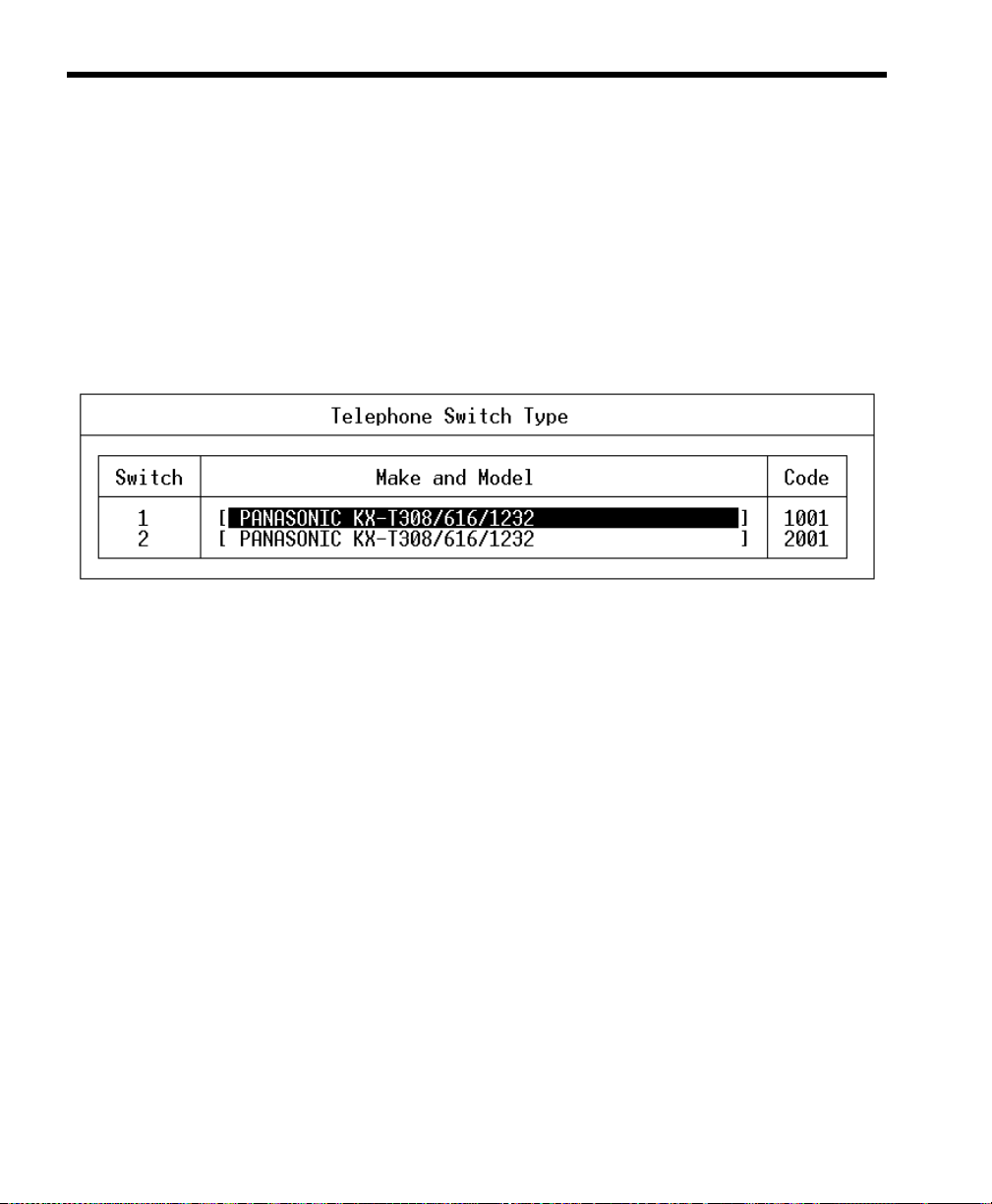
52 Installing Amanda@Work.Group/DOS
To define dial codes :
1. Run Setup as explained in “Running Setup” on page 49.
2. From the Configuration Utility menu, press 1 to select Telephone System Dial Codes.
The T elep hone S witc h Type screen lists 1001.PBX and 2001. PBX al ong
with the names of the switching systems they are based on or identifies
the switching system as not defined.
3. From the Telephone Switch Type screen, do one of the following:
• If the telephone switching system is the correct one (or if the tele-
phone switching system is the one you have used in the past—even
though it is identified as not defined):
• Select the file to be edited then press Enter.
Setup displays the dial codes and their descriptions.
• If the telephone switching system is not the one listed:
a. Select one of the .PBX files.
b. Press F2 to display a list of switching systems.
c. Use the arrow keys to select the name of your system or the
name of a system wh ic h has codes similar to yo urs then
press Enter.
d. Press Enter again t o display the di al codes and their des crip-
tions.
Page 65

Chapter 7: Defining Dial Codes 53
4. To change any dial codes that do not apply to your system:
a. Use the following Dial Codes Table to understand each of the
codes displayed on the screen.
b. Use the Up Arrow, Down Arrow, Tab, or Enter keys to select
the code you want to change.
c. Type the new code over the current code (if there is one).
(You can also use Backspace, Delete, spacebar, and the Right
Arrow and Left Arrow keys to edit the code.)
d. When you are finished, press F10 to save your changes.
(To return to the Telephone System Dial Codes screen without saving your changes, press Esc.)
e. Repeat steps A through D for any other codes to be changed.
5. When you have finished defining the dial codes, press Esc to return to
the Amanda Configuration Utility menu.
Dial Codes Table
Dial Code Label Description
What to dial to put the caller on transfer hold:
The code Amanda dials to ask the telephone switching sys tem to put the
caller on transfer hold before she transfers a caller to an extension.
Usually, this code is “F-” (a h ookflash followed by a hal f-second pause).
This may need to be changed to “F--” (a hookflash followed by a onesecond pause) or “F,” (a hookflash followed by a two-second pause) fo r
telephone switching systems that are slow to pro vide a transfer dial tone
after a hookflash. (Don’t use the quotation marks in the dial code.)
If tmo_dtwait is greater than 0, the number of dashes set for this option
is irrelevant. Use the value 0 for tmo_dtwait for faster call processing.
For more information about tmo_dtwait, see “What to dial to put the caller on transfer hold:” on page 53.
If you are editing C:\AMANDA\PBX.DB\1001.PBX instead of using
Setup, this is the dl_dtwait option.
Page 66

54 Installing Amanda@Work.Group/DOS
Dial Codes Table (Continued)
Dial Code Label Description
What to dial when there is
no transfer dial tone:
What to dial to return to
the caller after ring no answer:
What to dial to return to
the caller after busy:
The code Amanda dials to return to the caller if both of the following are
true:
You configure Amanda to wai t for a transfer dial tone before transferring
a call to an extension
There is no transfer dial tone
In this case, Amanda treats the attempted transfer as though the exten-
sion was busy.
Some telephone switching systems use “F-”, others use “-”. (Don’t use
the quotation marks in the dial code.)
If you are editing C:\AMANDA\PBX.DB\1001.PBX instead of using
Setup, this is the dl_ndtret option.
During supervised transfers, if the extens ion r ings th e s pecified n umber
of times but is not answered, Amanda dials this code to ask the telephone
switching system to reconnect the caller to Amanda. (See the questionnaire in “Chapter 10: Con figuring Amanda” for mo re informatio n about
configuring the number of rings.)
Usually, this code is “F-”. (Don’t use the quotation marks in the dial
code.)
If you are editing C:\AMANDA\PBX.DB\1001.PBX instead of using
Setup, this is the dl_rnaret option.
During supervised transfers, Amanda dials this code to ask the telephone
switching system to reconnect the caller to Amanda if the extension is
busy.
Usually, this code is “F-”. (Don’t use the quotation marks in the dial
code.)
If you are editing C:\AMANDA\PBX.DB\1001.PBX instead of using
Setup, this is the dl_bsyret option.
Page 67

Chapter 7: Defining Dial Codes 55
Dial Codes Table (Continued)
Dial Code Label Description
What to dial after a call
screening reject:
What to dial to connect a
caller to an extension:
What to dial before the
mailbox extension:
The code Amanda dials to reconnect to the caller if all of the following
are true:
Amanda is performing a supervised transfer
Call screening is ON
The user at the extension that was called rejects the caller
In this case, Amanda plays the mailbox’s current greeting.
Usually, this code is “F-”. (Don’t use the quotation marks in the dial
code.)
If you are editing C:\AMANDA\PBX.DB\1001.PBX instead of using
Setup, this is the dl_hupret option.
During supervised transfers, Amanda dials this code to complete the call
transfer after detecting an answer at the called extension. If call screening is ON, Amanda dials this code only after the user at the extension ac-
cepts the call.
Usually, this code is “H” (for Hang up). (D on’t us e the quotation marks
in the dial code.)
If you are editing C:\AMANDA\PBX.DB\1001.PBX instead of using
Setup, this is the dl_connect option.
If Amanda needs to dial something after dial tone detection, but before
dialing the extension number, enter that code here.
Usually this is left blank.
If you are editing C:\AMANDA\PBX.DB\1001.PBX instead of using
Setup, this is the dl_prefix option.
What to dial after the mailbox extension:
If Amanda needs to dial something after dialing the extension number,
enter that code here.
Don’t use an “H” for a blind transfer here becau se this setting is g lobal.
Sometimes you need “1-” to byp ass the hands-free answer feature (v oice
announce) on some telephone systems. (Don’t use the quotation marks
in the dial code.)
If you are editing C:\AMANDA\PBX.DB\1001.PBX instead of using
Setup, this is the dl_suffix option.
Page 68

56 Installing Amanda@Work.Group/DOS
Dial Codes Table (Continued)
Dial Code Label Description
What to dial on each port
after the system starts:
What to dial on each port
before shutdown:
What to dial when a port
goes off-hook:
What to dial to create or
record a conference call:
If you want Amanda to dial some initialization codes when she first
starts up, define those co des here. For example, yo u may want to remov e
call forwarding on the ports.
Usually this is left blank.
If you are editing C:\AMANDA\PBX.DB\1001.PBX instead of using
Setup, this is the dl_init option.
If you want Amanda to dial certain codes when she shuts down, define
those codes here. For example, enabling call forwarding on the ports lets
a live operator take the calls when Amanda shuts down.
Usually this is left blank.
If you are editing C:\AMANDA\PBX.DB\1001.PBX instead of using
Setup, this is the dl_stop option.
If Amanda must dial some special codes as she goes o ff-h ook to enab le
a special feature, define those special codes her e. For example, you may
enable special types of SMDI integration over a serial port.
Usually this is left blank.
If you are editing C:\AMANDA\PBX.DB\1001.PBX instead of using
Setup, this is the dl_pickup option.
Controls how to do a conference call when the called party answers the
telephone.
You provide the digits used to conference the caller, called party, and
Amanda (for example, “*3”). (Don’t use the q uotation marks in the dial
code.) If your telephone switc hing s ystem does no t have th is capabi lity,
leave it blank.
For example, if the Extension field for a mailbox contains 127KM,
Amanda dials 127. When an answer is detected, Amanda dials the conference dial code (such as “*3”) which conferences the caller, the called
party, and Amanda. Instead of hanging up when she connects the two
parties, Amanda records the conversation as a messag e in mailbo x 127.
If you are editing C:\AMANDA\PBX.DB\1001.PBX instead of using
Setup, this is the dl_conference option.
Page 69

Chapter 7: Defining Dial Codes 57
Dial Codes Table (Continued)
Dial Code Label Description
Number of seconds to wait
for dial tone detection:
Number of 1/100 seconds
to use for Flash time:
Which DTMF tone to listen to for hangup detection:
This is the number o f s econds Amanda waits for your telephone sw it ching system to provide a conti nuous di al tone for on e full seco nd. If yo ur
system has few DTMF receivers or intercom paths for call transfers, one
may not be immediately available for Amanda to transfer a call. In this
case, this number should be greater than 0.
Use 0 when Amanda does not wait for a dial tone (as when the telephone
switching system returns stutter dial tone or silence on a transfer). A
good value is 4 (seconds) when she does wait for a dial ton e. The r a nge
is 0–127.
If you are editing C:\AMANDA\PBX.DB\1001.PBX instead of using
Setup, this is the tmo_dtwait option.
Determines how long Amanda remains on-hook while performi n g a
hookflash. The value is in hundredths of seconds.
The usual value is 55 (just over half a second).
When set too short, the hookfl ash does not hap pen; when set too l ong, it
hangs up.
If you are editing C:\AMANDA\PBX.DB\1001.PBX instead of using
Setup, this is the flashtm option.
If your telephone switching system plays a specific DTMF tone or se-
quence of tones when a caller hangs up (to make hangup detection faster), enter that DTMF digit here.
If your telephone switching system has this capability, the code is usually the letter “d” which represents DTMF D. This may be a sequence of
DTMF digits rather than a single DTMF digit. The maximum length is
10 characters. If your system does not support this feature, leave it blank.
If you are editing C:\AMANDA\PBX.DB\1001.PBX instead of using
Setup, this is the dt_hangup option.
What to dial to turn on the
message waiting indicator:
What to dial to turn off the
message waiting indicator:
If your telephone switc hing system has message waiting indicators, enter
the code needed to turn the indicator on.
If your telephone switc hing system has message waiting indicators, enter
the code needed to turn the indicator off.
Page 70

58 Installing Amanda@Work.Group/DOS
Page 71

Chapter 8: Defining Tone Patterns
Using this Chapter
You can use either GetTones, an Amanda Company utility, AccuCall Plus, a
Brooktrout utility, to define tone patterns. Both are exp lained in this chapter.
Neither work with the RDSP/RTNI two-board combination. These utilities
do not know how to make MVIP connections to the DSP resourc e in order to
dial. The only solution is to use a 232 or 432 voice board while you define
the tones. Then you replace the 232 or 432 voice board with the ATI board
combination.
Using GetTones
Amanda must recognize telephone switching system tone patterns when
performing supervised transfers. The Setup utility runs another utility,
named GetTones, to “learn” the tone patterns for ringi ng, bus y, hang-up, and
reorder (also called fast busy).
Before running the GetTones utility, you must have satisfied all of the
following requirements:
• Define the dial codes. See “Chapter 7: Defining Dial Codes.”
• Connect ports 1 and 2 (the top RJ-14 jack of the first Brooktrout
board) to valid, working single-line extensions on the telephone
switching system.
• Know the extension number to which port 1 is connected.
• Verify that the extension to which port 1 is connected is not in any
hunt group, and does not have any call forwarding programmed.
Page 72

60 Installing Amanda@Work.Group/DOS
• Verify that the extension to which port 2 is connected has outside
line access and can dial a test telephon e number that is answered and
does not hang up after answering (time or weather lines are good
choices to call).
• Define a non-Amanda extension that has a telephone connected, is
not forwarded, and will not be answered. This becomes your Ring
No Answer (RNA) test station.
To define telephone switching system tone patterns:
1. Make sure that you have satisfied all the above requirements.
2. Run Setup as explained in “Running Setup” on page 49.
3. From the Configuration Utility menu, press 2 to select Telephone System Tone Patterns.
The GetTones for Brooktrout Voice Boards screen appears.
4. By default, the output file has the same name as your .PBX file. However, it ends with the extension .TON.
Page 73

Chapter 8: Defining Tone Patterns 61
5. Enter the out dial code, por t 1’s station number , the reor der cod e, and t he
RNA station number. Use the Up Arrow, Down Arrow, Tab, or Enter
key to move from one entry to the next.
outdial code Type the outside line access and telephone
numbers for a connection to test for tone patterns (such as the time or weather number). For
example:
9,5551111
Then press Enter.
port 1 station number Type the extension for a standalone (no call
hunting or forwarding) single-line (analog) extension connected to port 1.
Then press Enter.
reorder code Type any dial code that generates a reorder tone
pattern on the telephone switching system.
Typically, invalid extension numbers work
well, for example, 555 generall y works. If not,
try 444 or 777 or any number that generates a
fast busy tone pattern.
Then press Enter.
Ring No Answer
station number
6. Press F4 to run GetTones.
GetTones obtains the ring, busy, reorder, and hangup patterns of the
telephone switching system. Messages appear on your screen as the utility gets and tests these patterns.
Type a non-Amanda extension that has a telephone connected and is not answered or call
forwarded. If voice-announce or call-announce
is enabled, remember to enter the extension
plus the additional digit or digits that force the
extension to ring. For example, if the RNA test
station is 112, type:
1121-
Then press Enter.
Page 74

62 Installing Amanda@Work.Group/DOS
OTE
N
: If you have problems with the GetTones utility, such as not
getting good patterns or not being abl e to verify a t one p attern, try using AccuCall Plus, a Brooktrout utility that also
captures tone patterns. See “Using AccuCall Plus” on
page 62.
Using AccuCall Plus
The C:\AMANDA\PBX.DB\1001.T ON file defines the tone patterns that the
telephone switching system returns to Amanda. Amanda recognizes these
tones and uses her knowledge of them when she transfers calls. AccuCall
Plus is a Brooktrout utility that allows you to set up ring, busy, reorder/fast
busy/error, and special tone (such as a fax CNG tone) definitions.
This section is primarily for running tests that create new .TON files. If your
telephone switching system performs inband signaling integration, you may
not need the Ring No Answer (RNA) or ringback pattern.
You might edit an existing file to adjust the cadence or the percentage of
variation. For example, suppose a ring is usually one second on followed by
three seconds off. However, sometimes it is a bit shorter or longer. You may
want to increase the percentage of variation to allow for the differences. If
the busy and reorder tones are very similar, you might need to reduce the
percentage of variation to differentiate between them.
Amanda must be shut down before you run AccuCall Plus.
To run AccuCall Plus:
1. If Amanda i s running, sh ut down the Amanda syste m:
a. Press Alt+S (if Amanda is running as a standalone) or s (if
Amanda is running as a voice server).
b. Type in the password. (The default is AMandA with only the
first two and the last letter capitalized.)
c. Press Enter.
d. Press Y (to confirm the shutdown).
e. Press Y again (to reconfirm).
Page 75

Chapter 8: Defining Tone Patterns 63
When the C:\AMANDA prompt appears, you can start running AccuCall Plus.
2. Change directory to C:\ACCUCALL by typing:
cd c:\accucall
3. Press Enter.
4. You can create a new 1001.TON file or edit an existing file.
To create a new 1001.TON file, run AccuCall by typing:
accucall
To edit an existing 1001.TON file, run AccuCall by typing:
accucall C:\AMANDA\PBX.DB\1001.TON
5. Press Enter.
The AccuCall Plus main screen has several options. The list of function
keys at the bottom of the screen indicate which keys go with each
option.
Page 76

64 Installing Amanda@Work.Group/DOS
6. Select “AUTO RUN” by pressing F6.
Page 77

Chapter 8: Defining Tone Patterns 65
To define the Ring No Answer (RNA) tone pattern:
1. Type a telephone number for an extension in the Phone No. field. This
extension number must not be forwarded, not in a hunt group, not in
hands free/speaker phone mode, and not be answered by anyone.
2. Type 3 in the Verification Count field. This is the number of times you
want to run the test.
3. Type 10 in the Minimum Cycles field. This is the number of rings AccuCall Plus will listen to before completing the test cycle.
4. Select Full (the default) as the value for the Frequency Range field.
The possible values are:
Full (300 Hz to 1700 Hz)
High (800 Hz to 1700 Hz)
This is the range of frequencies that AccuCall Plus listens to.
5. The Frequencies Detected W indo w displays the f requencies detected b y
AccuCall Plus to characterize the tone.
6. The Cadence Detected W indow displays the cadence that AccuCall Plus
detected to characterize the tone. (This is displayed as a horizontal bar
graph.)
7. Press F9 to begin the test.
8. After AccuCall Plus has determined the system tone pattern, you can
customize the tone description using the Edit Tones box:
Name: Example: Panasonic Double Ring
Type: Ring1 if single ring, single pause
Ring2 if double ring, single pause
Terminating: NO
Cadence: NO
Frequency1: Determined by test
Frequency2: Determined by test
Page 78

66 Installing Amanda@Work.Group/DOS
PCPM Code: 8 (always for ring tones)
Quick Count: None
On Time: Determined by test
On Max Variation: Determined by test
On Min Variation: Determined by test
Off Time: Determined by test
Off Max Variation: Determined by test
Off Min Variation: Determined by test
9. Save the tone by pressing F8 (twice).
10. From the main screen, press F3 to go to the Filters screen. The Undefined Tone Frequencies box on the right side of the screen lists any
undefined frequencies that were found by the test.
11. Add these frequencies to the Filter table on the left side. Write each frequency in the Filter table, replacing the word “none” with the frequency.
12. Then press F10 to save this information and return to the main screen.
OTE
N
: All the listed frequencies must be at least 40 Hz apart
so Amanda can distinguish them.
To define the Busy tone pattern:
1. Fill in the telephone number for an extension that is offhook and
connected to either another internal extension or to an outside line.
2. Type 3 in the Verification Count field. This is the number of times you
want to run the test.
3. Type 10 in the Minimum Cycles field. This is the number of rings AccuCall Plus will listen to before completing the test cycle.
Page 79

Chapter 8: Defining Tone Patterns 67
4. Select Full (the default) as the value for the Frequency Range field.
The possible values are:
Full (300 Hz to 1700 Hz)
High (800 Hz to 1700 Hz)
This is the range of frequencies that AccuCall Plus listens to.
5. The Frequencies Detected W indo w displays the f requencies detected b y
AccuCall Plus to characterize the tone.
6. The Cadence Detected W indow displays the cadence that AccuCall Plus
detected to characterize the tone. (This is displayed as a horizontal bar
graph.)
7. Press F9 to begin the test.
8. After AccuCall Plus has determined the system tone pattern, you can
customize the tone description using the Edit Tones box:
Name: Example: Panasonic Busy
Type: Busy1 if regular busy cadence
Busy2 if double busy cadence
Terminating: YES (always)
Cadence: NO
Frequency1: Determined by test
Frequency2: Determined by test
PCPM Code: 7 (always for busy tones)
Quick Count: None
On Time: Determined by test
On Max Variation: Determined by test
On Min Variation: Determined by test
Off Time: Determined by test
Off Max Variation: Determined by test
Off Min Variation: Determined by test
Page 80

68 Installing Amanda@Work.Group/DOS
OTE
N
: A normal single busy to ne i s approximately 500 msec
on and 500 msec off.
9. Save the tone by pressing F8 (twice).
10. Press F8 to add the tone.
11. From the main screen, press F3 to go to the Filters screen. The Undefined Tone Frequencies box on the right side of the screen lists any
undefined frequencies that were found by the test.
12. Add these frequencies to the Filter table on the left side. Write each frequency in the Filter table, replacing the word “none” with the frequency.
Make sure that the busy frequencies are listed in the first four positions
in the table (these positions are for terminating tones). When a tone is a
terminating tone, Amanda does not wait for it to be repeated before taking control of the call.
13. Then press F10 to save this information and return to the main screen.
To define the Reorder/Fast Busy/Error tone pattern:
1. T ype a telephone number fo r an invalid exten sion in the Phone No. field.
This extension number must return the reorder tone. For example, you
might use 777 or 888. Test this tone from a single-line telephone before
you run this test.
2. Type 3 in the Verification Count field. This is the number of times you
want to run the test.
3. Type 10 in the Minimum Cycles field. This is the number of rings AccuCall Plus will listen to before completing the test cycle.
4. Select Full (the default) as the value for the Frequency Range field.
The possible values are:
Full (300 Hz to 1700 Hz)
High (800 Hz to 1700 Hz)
This is the range of frequencies that AccuCall Plus listens to.
Page 81

Chapter 8: Defining Tone Patterns 69
5. The Frequencies Detected W indo w displays the f requencies detected b y
AccuCall Plus to characterize the tone.
6. The Cadence Detected W indow displays the cadence that AccuCall Plus
detected to characterize the tone. (This is displayed as a horizontal bar
graph.)
7. Press F9 to begin the test.
8. After AccuCall Plus has determined the system tone pattern, you can
customize the tone description using the Edit Tones box:
Name: Example: Panasonic Reorder Tone
Type: Busy if normal reorder
Terminating: YES
Cadence: NO
Frequency1: Determined by test
Frequency2: Determined by test
PCPM Code: 7 (always for busy tones)
Quick Count: None
On Time: Determined by test
On Max Variation: Determined by test
On Min Variation: Determined by test
Off Time: Determined by test
Off Max Variation: Determined by test
Off Min Variation: Determined by test
9. Save the tone by pressing F8 (twice).
10. From the main screen, press F3 to go to the Filters screen. The Undefined Tone Frequencies box on the right side of the screen lists any
undefined frequencies that were found by the test.
Page 82

70 Installing Amanda@Work.Group/DOS
11. Add these frequencies to the Filter table on the left side. Write each frequency in the Filter table, replacing the word “none” with the frequency.
Make sure that the reorder frequencies are listed in the first four positions in the table (these positions are for terminating tones).
12. Then press F10 to save this information and return to the main screen.
To finish AccuCall Plus :
1. Press F7 to save the tone file.
2. Type the file name C:\AMANDA\PB X.DB\1001.TON.
3. Press F8 to save the file.
AccuCall Plus will not allow you to save to file unless you have defined
all the filters. It will also refuse to save to file if any two frequencies are
within 40Hz of each other.
If you have two frequencies that are closer than 40Hz, the best strategy
is to select a value that is between them and then go back to edit every
tone pattern that contains the two frequencies and replace them with that
value. To edit tones press <F8> from the main menu.
4. Exit the AccuCall Plus program by pressing F10.
Page 83

Chapter 9: Defining Integration Patterns
Using the Trace File for Integration
If your telephone switching system supports DTMF integration (also called
inband integration), you can:
1. Perform tests that add integration information to the TRACE.OUT file.
2. Convert that information to a set of integration strings.
3. Add the integration strings to the 1001.PBX file in the
C:\AMANDA\PBX.DB directory using the Setup or JOVE utilities.
OTE
N
: See “Chapter 12: Utilities,” in Administering Aman-
da@Work.Place for information about JOVE.
Depending on the telephone switching system you selected when you
defined dial codes (see “Defining Dial Codes” on page 51), some of the
integration patterns might be already filled in. Many telephone switching
systems are programmable, so existing patterns on the System Integration
Patterns screen may still need modification.
Make sure you define dial codes before performing the procedures in this
chapter. Otherwise you will overwrite all the integration information as the
Setup utility creates the 1001.PBX file for you using The Amanda
Company’s predefined .PBX file for the PBX that you select.
Page 84

72 Installing Amanda@Work.Group/DOS
Setting Up the Trace File
To check that trace files are being created:
1. If Amanda i s running, sh ut down the Amanda syste m.
2. At the DOS prompt, type the following to go to the root directory:
CD\
3. Then press Enter.
4. Edit the Amanda.bat file by typing:
JOVE AMANDA.BAT
5. Then press Enter.
The JOVE editor appears on the screen. Towards the bottom of the page
is a line that starts RAMANDA. You are ready to proceed if the line
reads:
RAMANDA /t5 /s1300 %1 %2 %3
If not, edit the line so that it is identical to this line.
6. To save and close the file, press the four following key combinations in
order:
Ctrl+X
Ctrl+S
Ctrl+X
Ctrl+C
7. At the DOS prompt, change directories to the pbx database by typing:
CD\AMANDA\PBX.DB
Then press Enter.
8. Edit the Pbx file by typing:
JOVE 1001.PBX
9. Then press Enter.
Page 85

Chapter 9: Defining Integration Patterns 73
10. Press Page Down display the lower portion of the file where the integration (if any) is displayed.
11. Use Down Arrow to move the cursor to the bottom of the file to a blank
line.
12. Type the following:
integration 10 ‘rrrrrrrrrr’
This new integration string will capture up to 10 digits of In Band Signaling that will be displayed in the trace file for later inclusion in
1001.PBX.
13. To save and close the file, press the four following key combinations in
order:
Ctrl+X
Ctrl+S
Ctrl+X
Ctrl+C
14. At the DOS prompt, type:
CD\
15. Then press Enter.
16. Start Amanda by typing:
AMANDA
17. Then press Enter.
Creating Test Patterns
After enabling the Trace capability and restarting Amanda, the telephone
switching system must be programmed to perform the following
capabilities:
• Select an extension that forwards on Ring No Answer to Amanda.
• Select another extension that forwards to the above extension on
Ring No Answer.
Page 86

74 Installing Amanda@Work.Group/DOS
• Select a third extension that forwards on Busy to Amanda.
• Select a fourth extension that forwards to the third extension on
Busy.
• Select a fifth extension that forwards all calls to Amanda.
• If applicable, create a hunt group that will forward back to Amanda
if the hunt group is busy or rings without answer.
• Create a Direct Inward Line by having an o utside CO trunk line r ing
at an extension that will forward on Ring No Answer and Busy to
Amanda. Tests 5 and 6 below do not have CO line identificat ion enabled. Tests 7 and 8 do.
Running the Tests
To run the tests:
1. Start Amanda by typing the following at the DOS prompt:
amanda
2. Then press Enter.
Test 1
• Place a call to the extension that forwards on Ring No Answer to
Amanda. Once Amanda has received the forwarded call, hang up.
Test 2
• Place a call to the second extension that is forwarded to the first extension. When Amanda has received the call, hang up.
Test 3
• Place a call to the third extension that forwards on Busy to Amanda.
Make sure that the extension is offhook and con nected to another extension or outside line. Once Amanda has received the bus y forwarded call, hang up.
Page 87

Chapter 9: Defining Integration Patterns 75
Test 4
• Place a call to the fourth extension that is busy forwarded to the third
extension. Make sure that both extensions are offhook and either
connected to each other, or to outside lines. Once Amanda has received the busy forwarded call, hang up.
Test 5
• Call in on the CO line that is directed to an extension that is forwarded to Amanda on Ring No Answer. Make sure that CO Line ID is
disabled. Once Amanda receives the call, hang up.
Test 6
• Call in on the CO line that is directed to an extension that is forwarded to Amanda on Busy. Make sure that the CO Line ID is disabled.
Once Amanda receives the call, hang up.
Test 7
• Repeat test 5 with CO Line ID enabled.
Test 8
• Repeat test 6 with CO Line ID enabled.
Test 9
• Call directly into Amanda from any extension. When Amanda answers the call, hang up.
Reading the Trace File
To read the trace file:
1. Shut down Amanda.
2. At the C:\AMANDA> prompt, type:
JOVE TRACE.OUT
Page 88

76 Installing Amanda@Work.Group/DOS
3. Then press Enter.
The first line should read similar to:
Oct 09 15:51:00 Begin trace of Amanda…
4. Press Ctrl+S to perform a search.
5. Type the following search text:
Using dtmf
6. Then press Enter.
The JOVE editor searches for the first call’s integration string. The cursor should move to the trace line that reads similar to:
Oct 09 15:53:00 ichan01: Using dtmf data:
#123
The # sign indicates a Ring No Answer forwarded call, and the 123 (for
example) is the extension that forwarded the call to Amanda. These digits could be any combination of DTMF digits. For example, the AT&T
Partner sends:
#03##123#
The #03## is the Ring No Answer code, and the 123# is the extension
number that forwarded. Different telephone switching systems (and
often different models) send different digits.
7. WRITE DOWN THE INTEGRATION INFORMATION FOR THIS
CALL.
8. Press Ctrl+S again.
9. Keep the same search string by just pressing Enter.
You should progress to the next call’s digits.
10. WRITE DOWN THE INTEGRATION INFORMATION FOR THIS
CALL.
Page 89

Chapter 9: Defining Integration Patterns 77
11. Repeat steps 8 through 10 until all 9 integration stings have been
recorded. Some of the strings may be identical (although the extension
may be different if you tested from different stations).
12. To return to the C:\Amanda> prompt, press the following key combinations:
Ctrl+X
Ctrl+C
To decide what integration strings to add to 1001.PBX:
1. Look at the integration string from Test 1. This represents a Ring No
Answer call that forwarded to Amanda. Locate the characters that match
the extension number that forwarded. On your notepad, rewr ite the
string so that the extension number is replaced by the lower case letter
r’s. For example, if your string w as “#123”, then your new string woul d
be “#rrr”. In the case of the Partner example, the “#03##123# would be
changed to “#03##rrr#.
OTE
N
: You may have 2, 3, 4 or more di gits in your ex tens ion
numbers. The number of r’s will match the number of
digits in your extension dial plan.
2. Go to the integration string for Test 2. It may be similar to the one
above, or it may contain a more complex string that has both the first
and second extensions listed. If the string is identical to the previous
string (for example, #03##123#), draw a line through it on your notepad.
If both extensions are listed, determine which number was the first
extension (originally called) and which was the second extension. If
your string looks similar to “#122123”, then the 122 was the second
extension, and 123 was the first extension. On your string, replace the
first extension with the lower case r’s and the first extension with lower
case s’s. Our example would look like “#sssrrr”. The Partner would
change from “#03##122#123#” to #03## sss #rrr#”.
3. The integration string from Test 3 may be identical to the string from
Test 1 (except for the extension number). If so, draw a line through it.
Page 90

78 Installing Amanda@Work.Group/DOS
If not, then your switch sends a unique busy forwarded integration to
Amanda. For example, the string may look like “*123”. The “*” denotes
a busy forwarded call, and the “123” is the extension that forwarded.
Replace the “123” with lower case b’s. Your string woul d now loo k like
“*bbb”.
4. The integration string from Test 4 may be identical to the one from Test
3. If so, draw a line through it.
If not, then identify the first extension number and replace the number
with lower case b’s. Identify the second extension number and replace
the number with lower case s’s. Your string may have looked like
“*122123” and should now look like “*sssbbb”.
5. The integration string from Test 5 is to differentiate a trunk based call
from a station based transfer if the switch offers this level of differentiation. If this string is identical to string one or three, draw a line through
it.
If not, evaluate the new string to see what other information was sent in
addition to “123” which is the forwarding extension. If the integration
string contains the trunk ID number (even though it is supposed to be
disabled), replace the numbers with either x’s (if the trunk ID is insignificant).
6. Repeat step 5 for the string from Test 6, but replace the extension number with b’s rather than r’s.
7. Repeat step 5 for Test 7. If the string is identical to the one from Test 5,
draw a line through it.
8. Repeat step 5 for Test 8, but replace the extension number with b’s
rather than r’s. If the string is identical to the one from Test 6, draw a
line through it.
9. Test 9 captures the signaling for a direct call into voice mail. The integration string probably includes a prefix (usu ally 1 d igit—but it could be
several digits) and the extension number of the calling user. Replace the
extension number with e’s.
Page 91

Chapter 9: Defining Integration Patterns 79
10. It is extremely important that there are no duplicate integration patterns.
T o make sure that each pattern is dif ferent, list them on a piece of paper ,
then rewrite them changing all character codes to zeros. What is left are
dial code masks which must all be different. For example, using the following dial codes:
dial code masks are
which are all different. If any dial code masks are the same, you must
modify the duplicates or delete them.
1***eee, #02#sss#rrr#
1***000, #02#000#000#
#03##rrr#
, and
#03##000#
, and
, the
,
Adding Integration Strings
You can define integration patterns using either one of the following:
• The Setup utility
• The JOVE editor to edit 1001.PBX.
To define DTMF integration patterns using the Setup utility:
1. Run Setup as explained in “Running Setup” on page 49.
2. From the Configuration Utility menu, press 3 to select Telephone System Integration Patterns.
The Telephone Switch Type screen appears.
3. From the Telephone Switch Type screen, select the name of your .PBX
file then press Enter.
Page 92
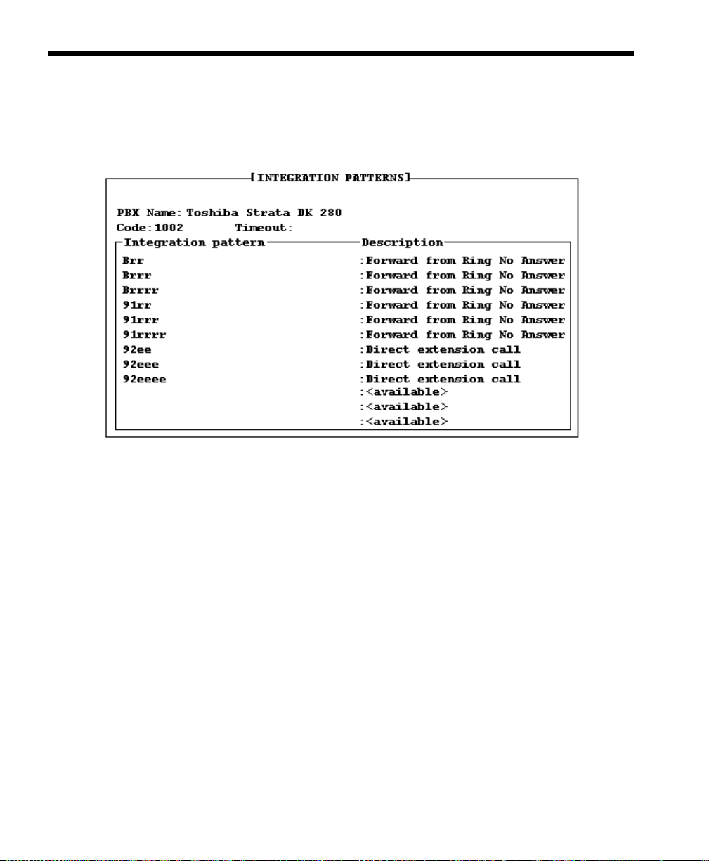
80 Installing Amanda@Work.Group/DOS
The Integration Patterns screen appears. Its first line tells the name and
code (a number between 1001 and 2001) for your switching system (if
they appear in the .PBX file). The following example shows a Toshiba
model.
4. Type a number of tenths of seconds in the Timeout box.
A value of 0 prevents integration. Any other value is the amount of time
that Amanda will wait for information from the telephone switching system. A suggested value for this timeout is 10 (which equ als 1 second). In
some cases you may need a value of 15 or 20.
Depending on the telephone switching system you selected when you
defined dial codes (see “Defining Dial Codes” on page 51), some of the
integration patterns might be already filled in.
OTE
N
: To move from the timeout field to the integration pat-
terns and vice versa, press Ctrl+Home.
5. Many telephone switching systems are programmable, so existing patterns on the System Integration Patterns screen may still need modification.
Page 93

Chapter 9: Defining Integration Patterns 81
Do one or more of the following:
• Verify that the existing patterns are accurate by checking the manual for your telephone switching system.
• Edit the existing patterns manually. (Select one, use the arrow keys
to move around, and type over anything that needs to be changed.)
For example, if the Ring No Answer pattern is #6rr, the rr stands for
any two-digit extension. If the #6 is accurate, but you plan to have
three or four-digit extension numbers, you must do some editing.
For three-digit numbers, change the Ring No Answer pattern to
#6rrr instead of #6rr. (See “Using Character Codes” on page 82 for
more information about rrr and other codes.)
• Delete a pattern by deleting all the characters in it.
To add integration strings to 1001.PBX using JOVE:
1. At the prompt, type:
CD PBX.DB
2. Then press Enter.
3. Type:
JOVE 1001.PBX
4. Then press Enter. This is the same file we edited earlier.
5. Press Down Arrow until you select the line that reads:
integration 10 ‘rrrrrrrrrr’
6. Press Delete to remove this line.
7. Take the integration strings you created in the previous pro cedur e. Type
each one on a separate line in 1001.PBX. For example:
integration 10 ‘#03##rrr#
integration 10 ‘#03##sss#rrr#
integration 10 ‘#00#ee#
Page 94

82 Installing Amanda@Work.Group/DOS
OTE
N
: The 10 is a suggested value for the timeout. 10 equals
1 second. Any other value is the amount of time that
Amanda will wait for information from the telephone
switching system. In some cases you may need a value
of 15 or 20. A value of 0 prevents integration.
These are in addition to the dial codes and any other integration strings
that may have been in the original file. Enter them at the end of the file.
Do not duplicate lines, but do remove any lines that are inaccurate.
8. To save and close the file, press the four following key combinations in
order:
Ctrl+X
Ctrl+S
Ctrl+X
Ctrl+C
To restart Amanda:
1. At the DOS prompt, type:
CD\
2. Then press Enter.
3. Type:
AMANDA
4. Then press Enter.
Using Character Codes
You must modify the DTMF patterns so that the integration patterns becom e
general (not specific to extensions 111 and 127). Call states and extension
information are defined by using one of the character codes shown below.
Each character code represents a call state, the position of the extension
number in the pattern, and the number of digits in the extension. When
inband signaling strings com e from the telephone switch ing system, Amanda
compares them to the defined integrati on pattern s and decides how to han dle
the calls.
Page 95

Chapter 9: Defining Integration Patterns 83
The character codes in the integration patterns are defined as follows:
Code Description
b Busy call state
When bbb (or bbbb ) app e ar s in the inte g r ation pattern, Amanda checks
the Busy Chain. If the Busy Chain is blank, she plays the custom busy
message for mailbox bbb ( or bbbb) or the system busy message.
c ANI or Caller ID digits
When a string of c’s appears in the integration pattern, Amanda stores the
DTMF characters at those locatio ns in t he port v ariable %H . With t oken
programming the %H can be used to identify callers and so forth.
e Direct dial call state (used to access a mailbox directly by Amanda asking
i Immediate record call state (plays the record tone and starts recording a
r Ring-no-answer call state that indicates who the call was for and that it
s Information regarding where the call came from (for handling message
for a security code)
When eee (or eeee) appears in the integration pattern, Amanda assumes
the caller wants to log in to mailbox eee (or eeee) and asks for the security
code.
message)
When iii (or iiii) appears in the integration pattern, Amanda begins re-
cording a message for mailbox iii (or iiii ) without play ing a prompt first.
was not answered
When rrr (or rrrr) appears in the integration pattern, Amanda checks the
Ring No Answer (RNA) Chain. If the RNA Chain is blank, she plays the
current greeting for mailbox rrr (or rrrr) or the system greeting.
See the configur ation option “int egration_greeti ng” on page 196 for information about how the system greeting can be played when an integrated call has both the rrr and sss (or rrrr and ssss) fields set.
replies)
If sss (or ssss) is found in the integration pattern along with b’s or r’s,
Amanda recognizes mailbox sss as the sender of the message—if one is
left.
:
T
IP
When using s’s, the integration requires User IDs for all telephones, even those in the file room and lobby.
Page 96

84 Installing Amanda@Work.Group/DOS
Code Description
t Trunk call or CO line ID; this can also be used for dynamic port alloca-
x Wild card that matches anything (use this carefully)
tion
When ttt (or tttt) appears in the integration pattern, Amanda processes
mailbox ttt (or tttt) normally. Whenever a call comes in on trunk line 3,
for example, mailbox 3 is processed. If trun k lines 1 to 20 support two
companies that share an Amanda system, mailbox’s 1–10 can have
@G(990) in their Extension fields—causing Amanda to play one company’s greeting. mailbox’s 11–20 can have @G(880) in their Extension
fields—causing Amanda to play the other company’s greeting.
For example 6xxxx would match every inband signaling string that had
a 6 followed by four other characters.
Realize that the character codes you use define not only the placement of the
extension information in the pattern, but also the call state, that is, Ring No
Answer, Busy, Direct, and so forth. Therefore, you can control Amanda’s
behavior based upon your specific requirements. For example, if your
customer does not wish to allow for Busy call states, then modify the
integration character codes and replace the b’s with r’s.
Some telephone switching systems have timing problems that cause the first
DTMF digit to be missed. In such cases, it is useful to add integration
patterns that are variations of the current patterns. For example, you might
add a second pattern for Direct calls (
1***eee
in our example) as
***eee
These are identical—except the first digit is missing in the second pattern.
You can also try reducing the delay time (Delay op tion on SMDI t ab in Setup
utility).
.
Never remove leading digits from a pattern if they differentiate this pattern
from another or if they are “active” digits (such as r’s and b’s).
Page 97

Chapter 9: Defining Integration Patterns 85
Running Integration Helper
If you know that your telephone switching system supports DTMF
integration, the Integration Helper utility also allows you to determine the
integration patterns.
Before running the Integration Helper be sure that you:
• Enable your telephone switching system for voice mail integration.
• Program a test extension for call coverage, or call forwarding on
Ring No Answer and Busy, to Amanda. The follo wing procedure assumes that this extension is 111, but it can be any extension.
• Make another extension available for placing test calls. The following procedure assumes that this extension is 127.
To run Integration Helper:
1. Press F4 to run the Integration Helper utility.
The following appears on the screen:
Integration Helper—Waiting for a call on any
port…To abort press ESC…
2. Place sample calls by calling from the available extension (127) to your
test extension (111). Use these calls to generate DTMF tones so Integration Helper can capture them. You can capture Ring No Answer, Busy,
and Direct call codes—using extensions and CO trunk lines. See “Placing Test Calls” on page 86.
3. As a code is captured, it appears on the Edit Integration Pattern screen.
You see the captured pattern on two lines, one that is for display only
and the other which you edit. For example, you need to replace extension numbers with patterns such as rrr for ring no answer. (See “Using
Character Codes” on page 82 for more information.)
4. When you have finished, press Esc to return to the System Integration
Patterns screen. The screen should be filled with the captured DTMF
digits (per your edits) and the descriptions of those codes.
Page 98

86 Installing Amanda@Work.Group/DOS
Placing Test Calls
You can place test calls of the following types:
Available extension (127) calls the test extension (111) for Ring No
Answer:
After a Ring No Answer condition occurs, the call should be forwarded to
the Integration Helper program which answers the call and captures the
DTMF digits played by the telephone switching system. You define what
type of test call you made.
Available extension (127) calls the test extension (111) while the test
extension is Busy:
Verify that the test extension (111) has been call forwarded Busy to the
single-line ports you h ave p rogrammed for Aman da. Make th e test exte nsion
(11 1) Busy. From the available extension (127), call the test extension (111).
The test extension (111) should forward to the single-line ports im m edi ately
after the Integration Helper captures the DTMF digits (if any).
Test extension (111) calls directly to Integration Helper:
From the test extension (111), call the single-line ports. Integration Helper
captures the DTMF digits (if any). Note that some telephone switching
systems use different codes depending upon whether this direct call was
made by dialing an extension or by pressi ng a message lig ht. You should run
both tests if you suspect this to be true of your system.
Availa ble extension (127) using a CO line calls in and rings the test
extension (111) for Ring No Answer:
From the available extension (127), select an outside CO line and call in to
where you are installing Amanda. When the receptionist answers, ask to be
blind transferred to the test extension (111), which should forward to the
Integration Helper after a certain number of rings.
Page 99

Chapter 9: Defining Integration Patterns 87
A vailable extension (127) using a CO line calls in while the test extension
(111) is Busy:
Make the test extension (111) busy. From the available extension (127),
select an outside CO line and call the company where you are installing
Amanda. When the receptionist answers, ask to be blind transferred to the
test extension (111), which should forward to the Integration Helper
immediately.
Forward from Ring No Answer Example
You may have two patterns labeled “Forward from Ring No Answer.” Both
should contain the extension number (111) that was call forwarded to the
Integration Helper. This is the extension that did not answer. One of the
patterns may contain the available extension number you called from (127).
For example, suppose the integration patterns were:
#02#127#111#
and
#03##111
You replace the digits of the test extension (111, the extension that did not
answer) with r’s and the digits of the telephone from which the call was
made, 127, with s’s:
#02#sss#rrr#
and
#03##rrr
Page 100

88 Installing Amanda@Work.Group/DOS
This takes care of extensions that have exactly three digits (such as 111 and
127). To handle four-digit extensions, for example, you would have used:
#02#ssss#rrrr#
and
#03##rrrr
Direct Call Example
As a result of the Direct test call, one pattern should be labeled “Direct
call…” and contain the extension number for the telephone from which you
called (111).
Replace the extension number with e’s. For example, change:
1***111
to:
1***eee
This takes care of extensions that have exactly three digits (such as 111 and
127). To handle four-digit extensions, for example, you would have used:
1***eeee
Forward from Busy Example
For patterns labeled “Forward from Busy,” you replace the extension number
that was busy with b’s. If there is a pattern that contains the extension from
which the call was made, replace the extension number with s’s.
 Loading...