

Amana VTC093B-0, VTC093B-2, VTC09EB-3, VTC093B-4, VTC123B-0 Product Specifications
...
PRODUCT SPECIFICATIONS
VTC / VTH
VERTICAL TERMINAL
A
IR CONDITIONER AND HEAT PUMP
No other unit in the industry offers so many
extras already built in as standard on every
unit. Don’t settle for anything less than the
Amana® brand Standard Ad van tage!
Evaporator Coil Freeze Pro tec tion
•
Compressor Restart Delay
•
Low Ambient Lock-out
•
Manual Outside Air Damper
•
Wall-mount Thermostat
•
Electrical Disconnect
•
Random Unit Restart
•
Front Desk Control
•
Fan On/Off Delay
•
High-effi ciency Operation
•
Quiet Operation
•
Reliability and Durability
•
¾ Ton through 2 Tons
SS-VTAC www.goodmanmfg.com 5/08
COOLING: 8,350 - 23,800 BTU/H
H
EAT PUMP: 8,120 - 22,800 BTU/H
ELECTRIC HEAT: 5,100 - 34,100 BTU/H
UP TO 3.5 COP
Supersedes 12/07

P
RODUCT SPECIFICATIONS
FEATURES
Front Desk Control
•
Enable or disable each unit from the front desk to save energy
used to con di tion unoccupied rooms.
Fan Delay
•
Allows the evaporator blower to con tin ue running for up to 45 sec .
after the ther mo stat is satisfi ed, maximizing cooling performance.
Random Restart
•
Protects against damage to electrical circuits by preventing all
units from starting at one time after power disruption. Random
restart occurs in 3 to 4 min.
Evaporator Coil Freeze Protection
•
Prevents ice build-up on coils and compressor damage during
the cooling mode. Attached to the coil, a temperature sensor
will de-energize the compressor when freezing conditions are
detected and re-energize the compressor when the coil warms
up again.
Ductable Return Air
•
Permits the con nec tion of return air ductwork using the provid-
ed tabs (usually not required) on the inlet of the evap o ra tor coil.
(Figure 5, pg. 9)
Note: Duct systems and registered sizes must be properly designed for
the CFM and external static pressure rating of the unit.
Adjustable Outside Air (manual)
•
Meets code re quire ments for outside air introduction. The air
vent (Figure 6, pg. 9) allows up to 50 CFM of outside air to be
introduced into the equipment closet. The air mixes with return
air entering the closet through the return air grille.
Note: Negative pressure can be introduced through an external source to
raise the 50 CFM level. Consult with the factory.
Compressor Restart Delay – (3 min.)
•
Ensures that system pressure equalizes before the system re-
starts, so compressor life is extended.
Low Ambient Lockout
•
Locks out compressor at 40ºF and below, thus extending com-
pressor life.
Electrical Dis con nect (Factory-installed)
•
Makes service and maintenance easier.
Filter Brackets (Field-installed)
•
Installed over evaporator coil and shipped with throw-away fi l-
ter (20” x 24” x 1”; see Figure 5, pg. 9).
Unique “Sleeve Drain” Condensate System
•
(Factory-installed) – Connects evaporator drain pan to a vertical
pipe connection in the unit’s base pan via a drain line. Evaporator condensate is delivered from the unit to a catch tray in the
wall sleeve and exits the sleeve through the ¾” male NPT fi tting
to allow complete piping of the drain to a condensate riser during the rough-in stage. This eliminates condensate connection
problems when connecting the HVAC drain to the riser after the
HVAC unit is installed in the closet. Unit can be removed for
service without disconnecting the condensate piping. Additional
closet space is not needed to connect the drain.
Secondary Overfl ow
•
Should the primary condensate riser become clogged, water will
fi ll the catch tray and be diverted through the sleeve to the exterior of the building, ensuring no leakage into the interior area.
Rain water entering the sleeve is automatically diverted to the
building exterior.
NOMENCLATURE
VT 09
4,5
3
Product Category Engineering
V Vertical Package Revisions
Terminal Unit
Model Type A Standard Model
C Air Conditioner H Hot Water Model
H Heat Pump
System Cooling Capacity 00 0.0 KW 05 5.0 kW
09 9,000 BTU/h 02 2.0 KW 06 6.0 kW
12 12,000 BTU/h 03 3.0 kW 08 8.0 kW
18 18,000 BTU/h 04 4.0 kW 10 10 kW
24 24,000 BTU/h Hot Water Models (H)
Voltage Design Series
3 230/208v-60 Hz-1 Ph A Unit manufactured prior to 01/2006
B
3
7
6 8,9
A11AC
03
101,2
Option Code
230v-208v Models
0A 2-row coil 0B 3-row coil
B Unit meets 2006 DOE requirement
Electric Heat
2 www.goodmanmfg.com SS-VTAC
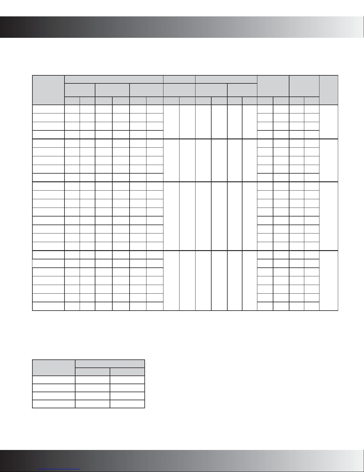
VTC MODEL SPECIFICATIONS—COOLING/ELECTRIC HEAT
ELECTRICAL DATA (208/240V-1 PH-60HZ)
P
RODUCT SPECIFICATIONS
Model
VTC093B-0
VTC093B-2
VTC09EB-3
VTC093B-4
VTC123B-0
VTC123B-2
VTC123B-3
VTC123B-4
VTC123B-5
VTC183B-0
VTC183B-2
VTC183B-3
VTC183B-4
VTC183B-5
VTC183B-6
VTC183B-8
VTC183B-10
VTC243B-0
VTC243B-3
VTC243B-4
VTC243B-5
VTC243B-6
VTC243B-8
VTC243B-10
Electric Heat Data Blower Data Condenser Data
kW BTU/h
240V 208V 240V 208V 240V 208V AMPS HP RLA LRA FLA HP 208V 230V 208V 230V
0 0.0 0.0 0.0 0.0 0.0
2 1.5 6,800 5,100 9.0 7.9 10 12 15 15
3 2.25 10,200 7,700 13.2 11.5 15 18 20 20
4 3.0 13,600 10,200 17.4 15.1 19 23 20 25
0 0.0 0.0 0.0 0.0 0.0
2 1.5 6,800 5,100 9.0 7.9 10 12 15 15
3 2.25 10,200 7,700 13.2 11.5 15 18 20 20
4 3.0 13,600 10,200 17.4 15.1 19 23 20 25
5 3.75 17,000 12,800 22.0 19.0 24 28 25 30
0 0.0 0.0 0.0 0.0 0.0
2 1.5 6,800 5,100 9.2 8.1 13 13 15 15
3 2.25 10,200 7,700 13.4 11.7 15 18 20 20
4 3.0 13,600 10,200 17.5 15.3 19 23 25 25
5 3.75 17,000 12,800 22.0 19.0 24 28 25 30
6 4.5 20,500 15,350 26.0 23.0 28 34 30 35
8 6.0 27,300 20,500 34.0 30.0 37 44 40 45
10 7.5 34,100 25,600 43.0 37.0 47 54 50 60
0 0.0 0.0 0.0 0.0 0.0
3 2.25 10,200 7,700 14.0 12.3 18 18 20 20
4 3.0 13,600 10,200 18.2 15.9 21 24 25 25
5 3.75 17,000 12,800 22.0 20.0 26 28 30 30
6 4.5 20,500 15,350 27.0 23.0 30 34 35 35
8 6.0 27,300 20,500 35.0 30.0 39 45 45 50
10 7.5 34,100 25,600 43.0 38.0 48 55 50 60
Total Heating
Amps
Evaporator
Motor
0.72 1/8 3.7 21 0.5 1/15
0.72 1/8 5.0 24 0.5 1/15
0.87 1/8 9.0 48 0.72 1/10
1.4 1/4 10.5 61 2.3 1/4
Compressor
Condenser
Motor
Minimum
Circuit
Ampacity
7 7 15 15
10 10 15 15
13 13 15 15
18 18 20 20
Maximum
Circuit
Protection
Ship
Weight
245
245
255
255
OOLING PERFORMANCE DATA
C
Model
VTC093B
VTC123B
VTC183B
VTC243B
¹ T ested in accordance with ARI Standard 310/380-93
at 95°F DB/75°F WB outdoors and 80°F DB/67°F
WB indoors.
SS-VTAC www.goodmanmfg.com 3
Standard Ratings
BTU/h EER
8,350 9.3
11,500 9.6
18,900 9.7
23,100 9.1
1
P
RODUCT SPECIFICATIONS
VTC MODEL SPECIFICATIONS—COOLING/ELECTRIC HEAT (CONT.)
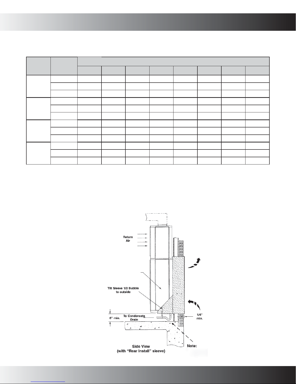
BLOWER DATA
Model
VTC093B
VTC123B
VTC183B
VTC243B
Notes:
(1) VTC12, 18- and 24-blower motors are factory-wired for medium (cooling) and low (heating) fan operation.
VTC09 is low speed for both.
(2) VTH12, 18- and 24-blower motors are factory-wired for medium (cooling/heat pump) and low (electric heat) speed operation.
VTH09 is low speed in all modes.
Motor
Speed
Connection
High 490 475 460 450 435 420 400 ---
Med 375 360 350 340 330 315 300 ---
Low 290 280 270 260 240 230 215 ---
High 490 475 460 450 435 420 400 ---
Med 375 360 350 340 330 315 300 ---
Low 290 280 270 260 240 230 215 ---
High 660 655 650 645 640 635 625 610
Med 580 578 575 570 565 560 550 540
Low 485 480 475 470 465 460 455 450
High 1,030 1,000 980 950 920 890 860 820
Med 880 860 840 820 790 760 730 710
Low 770 760 750 740 720 700 680 660
0.05 0.10 0.15 0.20 0.25 0.30 0.35 0.40
CFM vs. External Static Pressure
DIMENSIONAL DATA
*See Wall Sleeve Installation
In struc tions for complete
details.
VTC/VTH Unit
4 www.goodmanmfg.com SS-VTAC
"P" Trap Is shown for illustration
purposes only. It may not be
required by local codes.
 Loading...