

Page 1
International Commercial Microwave—Technical Information
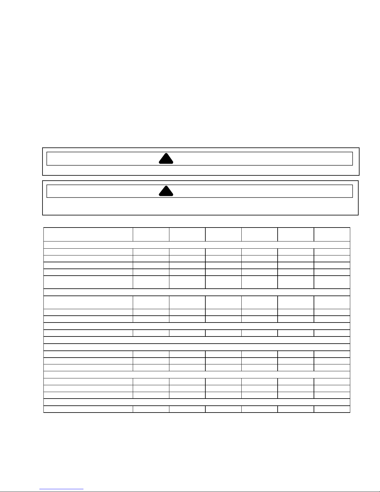
230 V, 50 Hz Models
UHDC5112 P1331234M
HDC5142 P1331237M UHDC5142 P1331238M
HDC5182 P1331241M UHDC5182 P1331242M
DEC11E2 P1331235M UC11E2 P1331236M
DEC14E2 P1331239M DEC18E2 P1331243M
UC14E2 P1331240M UC18E2 P1331244M
• Due to possibility of personal injury or property damage, always contact an authorized technician for servicing or
repair of this unit.
• Refer to Service Manual RS5320013 for detailed installation, operating, testing, troubleshooting, and disassembly
instructions.
CAUTION
!
All safety information must be followed as provided in Service Manual RS5320013.
!
To avoid risk of electrical shock, personal injury, or death, disconnect power to oven and discharge capacitor
before servicing, unless testing requires power.
Models UHDC5112
UC11E2
Power Source
Voltage AC 230 VAC 230 VAC 230 VAC 230 VAC 230 VAC 230 VAC
Amperage (single unit) 13 A 13 A 13 A 13 A 13 A 13 A
Frequency 50 Hz 50 Hz 50 Hz 50 Hz 50 Hz 50 Hz
Single phase, 3 wire earthed X X X X X X
Plug BS 1363A CEE 7/7
Power Output
Nominal microwave energy
(IEC705)
Minimum temperature rise (∆T) 11ºF/5.5ºC 11ºF/5.5ºC 14ºF/7.5ºC 14ºF/7.5ºC 18ºF/10ºC 18ºF/10ºC
Operating frequency 2450 MHz 2450 MHz 2450 MHz 2450 MHz 2450 MHz 2450 MHz
Power Consumption
Cook condition microwave 1800 Watts 1800 Watts 2300 Watts 2300 Watts 3000 Watts 3000 Watts
Dimensions
Cabinet
Width 423 mm 423 mm 423 mm 423 mm 423 mm 423 mm
Height 335 mm 335 mm 335 mm 335 mm 335 mm 335 mm
Depth 548 mm 548 mm 578 mm 578 mm 578 mm 578 mm
Oven Interior
Width 331 mm 331 mm 331 mm 331 mm 331 mm 331 mm
Height 175 mm 175 mm 175 mm 175 mm 175 mm 175 mm
Depth 305 mm 305 mm 305 mm 305 mm 305 mm 305 mm
Weight
Crated 29 kg 29 kg 31 kg 31 kg 31 kg 31 kg
1100 Watts 1100 Watts 1400 Watts 1400 Watts 1800 Watts 1800 Watts
WARNI NG
DEC11E2 UHDC5142
UC14E2
BS 1363A CEE 7/7
Schuko
HDC5142
DEC14E2
Schuko
UHDC5182
UC18E2
BS 1363A CEE 7/7
HDC5182
DEC18E2
Schuko
November 2006 16027612
©2006 Maytag Services
1
Page 2
Component Specifications
!
WARNING
To avoid risk of electrical shock, personal injury, or death, disconnect power to oven and discharge capacitor
before servicing, unless testing requires power.
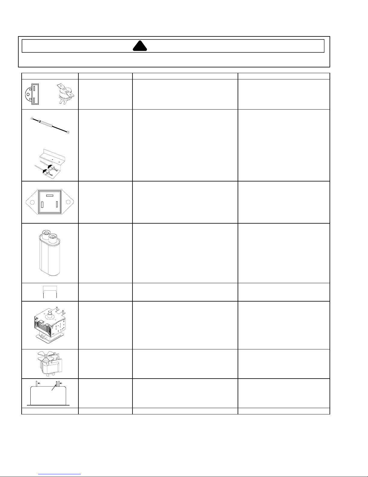
Illustration Component Testing Results
Open at 104° C (219° F).
Open at 138° C (280° F) and
closed at 82° C (180° F).
Infinite resistance should be
measured in one direction and 50KΩ
or more in the opposite direction.
NOTE: Analog meter must contain a
battery of 6 volts minimum.
Caution - Do not operate oven
when wire to terminal MT2 is
removed.
Infinite.
Approximately 40 Ω or more.
Infinite.
Infinite.
Between Terminals: Meter should
momentarily deflect towards zero
then return to over 5 MΩ. If no
deflection occurs, or if continuous
deflection occurs, replace capacitor.
Terminal to Case: Infinite
resistance.
Infinite.
Between Terminals: Less than 1 Ω.
Each terminal to ground measures
Infinite resistance.
NOTE: This test is not conclusive. If
oven does not heat and all other
components test good, replace the
magnetron and retest.
Approximately 30 Ω.
1100 Watt units
1400 and 1800 Watt
units
MT2
MT1 GA TE
Thermal Cutout Disconnect all wires from TCO.
Diode Assembly
Triac Disconnect wires to triac.
Capacitor
Snubber Assembly Disconnect wires to snubber.
Magnetron
Blower Motor Remove all wires from motor.
Measure resistance across terminals.
Cavity Thermal Fuse..................................
Magnetron TCO .........................................
Discharge Capacitors
Remove diode lead from capacitor and
connect ohmmeter.
Reverse leads for second test.
Measure resistance from:
MT1 to MT2 ...................................................
MT1 to Gate...................................................
MT2 to Gate...................................................
All terminals to ground ...................................
Discharge Capacitors
Remove wires from capacitor terminals and
connect ohmmeter, set on highest
resistance scale to terminals.
Also check between each terminal and
capacitor case.
Measure resistance across terminals.............
Discharge Capacitors
Remove wires from magnetron and connect
ohmmeter to terminals. Also check
between each terminal and ground.
Measure resistance across coil......................
Line
Wire Harness Test continuity of wires .................................. Continuity.
Load
Earth
Line filter Line to Line....................................................
16027612 November 2006
Load to Load..................................................
Line to Load ...................................................
Any terminal to Earth .....................................
2
.8 MΩ
.
.8 MΩ
.
Continuity.
Infinite.
©2006 Maytag Services
Page 3
Component Specifications
!
WARNING
To avoid risk of electrical shock, personal injury, or death, disconnect power to oven and discharge capacitor
before servicing, unless testing requires power.
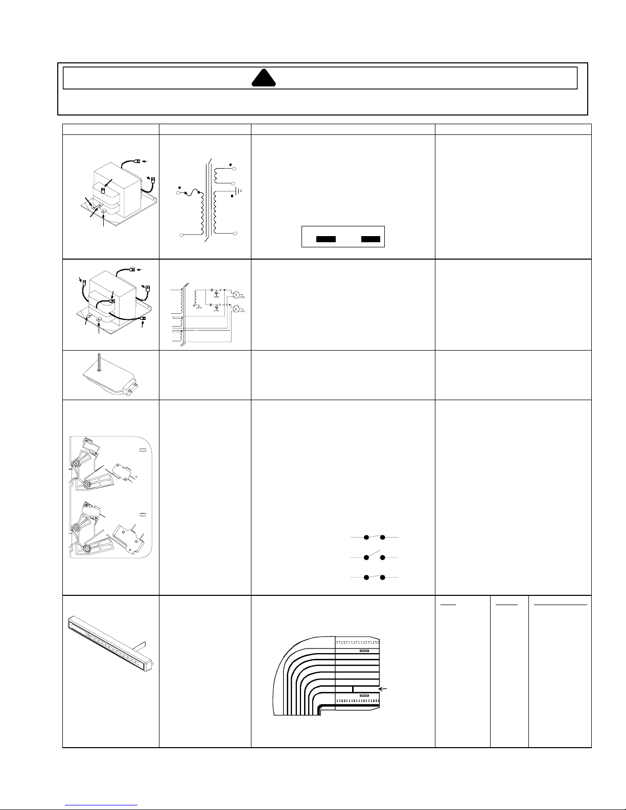
Illustration Component Testing Results
This transformer is equipped with a
155° C thermal cutout.
1.3 Ω
.
1.3 Ω
.
<1 Ω
.
70 Ω
.
Infinite resistance. If not, replace
transformer.
1 Ω
.
<1 Ω
.
<1 Ω
.
45 Ω
.
Infinite resistance. If not, replace
transformer.
Approximately 12 KΩ
.
COM
220
6
COM
230
230
Transformer
1100 Watt
6
5
4
(COM)
3
Discharge Capacitor
Remove all wires from terminals, and
measure resistance from:
5
220 to Common...............................................
230 to Common...............................................
6
Terminal 5 to 6 ................................................
Terminal 4 to Earth screw on transformer .......
Terminal 4 to any other terminal......................
(230V)
1
Transformer
5
1800 and 1400 Watt
8
4
7
#
# 1
# 2
#
# 6
# 7
#
4
5
8
Stirrer motor
230 VAC
4
3
1
Gray Pink
Discharge Capacitor
Remove all wires from terminals, and
measure resistance from:
230 to Common...............................................
Terminal 5 to 6 ................................................
Terminal 7 to 8 ................................................
Terminal 4 to Earth screw on transformer .......
Terminal 4 to any other terminal......................
Remove all wires from motor.
Measure resistance across terminals..............
Interlock switch
assembly
Monito r
Primary /
Logic
Secondar y
Touch Panel
Assembly
Disconnect wires to switch.
With door open measure resistance from:
Terminal C to NO Primary ..........................
Terminal C to NO Secondary .....................
Terminal C to NC Monitor...........................
With door closed measure resistance from:
Terminal C to NO Primary ..........................
Terminal C to NO Secondary .....................
Terminal C to NC Monitor...........................
Door Closed
Primary / Logic
Monitor
Secondary
C
C
C
NO
NC
NO
Continuity is indicated as 100 Ω and below.
Pin 1: Ground.
10
9
8
7
6
5
4
3
2
1
Split
Infinite.
Infinite.
Continuity.
Continuity.
Continuity.
Infinite.
Pad
1
2
3
4
5
6
7
8
9
0
Start
Stop/Reset
Power Level
X 2
Time Entry
Trace
8 & 10
7 & 10
6 & 10
5 & 10
4 & 10
3 & 10
8 & 9
7 & 9
6 & 9
5 & 9
4 & 9
4 & 8
5 & 8
6 & 8
7 & 8
Measurement
Continuity
Continuity
Continuity
Continuity
Continuity
Continuity
Continuity
Continuity
Continuity
Continuity
Continuity
Continuity
Continuity
Continuity
Continuity
November 2006 16027612
©2006 Maytag Services
3
Page 4

Component Specications
!
WARNING
To avoid risk of electrical shock, personal injury, or death, disconnect power to oven and discharge capacitor
before servicing, unless testing requires power.
Illustrati stluseR gnitseT tnenopmoC no
Line voltage to control board
P2 connector
Pin 1—Pin 3..............................................
Output drive voltage to triac
10
Triac terminals............................................
Gate—T1..................................................
Fan relay (controls blower motor, antenna
motor(s), and oven light)
Control board ..............................................
Terminals C—J.........................................
Cook relay
Control board ..............................................
Terminals F—K.........................................
Line voltage (All Conditions).
0 VAC (Idle and Standby).
0.9 VAC (Cook).
Line voltage (Idle).
0 VAC (Standby and Cook).
Line voltage (Idle).
0 volts (Standby and Cook).
P2
Pin #1
Pin #1
Controller board
K
F
J
C
B
A
1
P2
10
P1
P1
P1 connector used
for touch panel
ribbon
1
Error Code Table
Error Code Corrective Action
F1 Replace HV/LV Board
F2 Replace HV/LV Board
F3 Replace HV/LV Board
F4 Replace HV/LV Board
F5 Replace Touch Panel
Usage Test
The Usage Test is used to access Magnetron Hours, Magnetron Cycles and Door Cycles. Use the following
procedure to access the data:
F6 Replace HV/LV Board
1. Open door.
2. Press and hold pad 3 for ve (5) seconds.
NOTE: After ve (5) seconds, SErv illuminates in the display.
3. Press pad 1 for Magnetron Hours.
4. Press pad 2 for Magnetron Cycles.
5. Press pad 3 for Door Cycles.
Conditions
Initial Power Up Condition: Apply power to oven with door closed.
Idle Condition: Oven plugged in, display blank (no other components operating).
Standby Condition: Open oven door, light and motors operate.
Cook Condition: Food load
in oven, coo
k cycle initiated.
4
©2006 Maytag Services
6002 rebmevoN 21672061
Page 5

Component Specifications
!
To avoid risk of electrical shock, personal injury, or death, disconnect power to oven and discharge capacitor
before servicing, unless testing requires power.
WARNING
Power Test
All Amana and Menumaster microwave oven power outputs are rated using the IEC705 standards. Using the IEC705
test method requires precision measurements and equipment that is not practical to be performed in the field. Using
the test shown below will indicate if the oven performance is satisfactory.
Test equipment required:
• 1000 ml test container and thermometer (Amana power test kit R0157397 Fahrenheit / Menumaster power
test kit M95D5 Celsius).
• Digital watch / watch with a second hand for use on ovens with electromechanical timers.
Important Notes:
• Low line voltage will cause low temperature rise / power output.
• Ovens must be on a dedicated circuit, properly grounded, and polarized. Other equipment on the same
circuit may cause a low temperature rise / power output.
• This test and results are not a true IEC705 test procedure and are only intended to provide servicers with an
easy means of determining if the microwave oven cooking output is correct.
Procedure
1. Fill the test container to the 1000 ml line with cool tap water.
NOTE: Water temperature should be approximately 60°
2. Using the thermometer, stir water for five to ten seconds; measure, and record the temperature (T1).
3. Place test container of water in the center of oven cavity and close door.
4. Heat the water for a 33-second full power cycle.
NOTE: Use a digital watch or a watch with a second hand for ovens with electromechanical timers.
1. At end of the cycle, remove test container. Using the thermometer, stir water for five to ten seconds and record
temperature (T2).
2. Subtract the starting water temperature (T1), from the ending water temperature (T2) to obtain the temperature
rise (∆T).
3. If the temperature rise (∆T) meets or exceeds the minimum, the test is complete. If the temperature rise (∆T)
fails to meet the minimum temperature rise, test the line voltage to verify it is correct. Then repeat steps 1-6
making sure to change the water. If the temperature rise (∆T) fails to meet the minimum temperature rise again
the oven will require service.
F / 16° C.
Minimum Temperature Rise at Thirty-Three (33) Seconds Run Time
∆T Cooking ∆T Cooking ∆T Cooking ∆T Cooking
(°F) Power Output (°F) Power Output (°C) Power Output (°C) Power Output
10 .................1000 20 ................. 2000 5 .............. 1000 11............ 2000
11 .................1100 21 ................. 2100 5.5 ............ 1100 11.5......... 2100
12 .................1200 22 ................. 2200 6.5 ............ 1200 12............ 2200
14 .................1400 24 ................. 2400 7.5 ............ 1400 13............ 2400
17 .................1700 25 ................. 2500 9.5 ............ 1700 13.5......... 2500
18 .................1800 27 ................. 2700 10 ............. 1800 15............ 2700
19 .................1900 30 ................. 3000 10.5 .......... 1900 16.5......... 3000
November 2006 16027612
©2006 Maytag Services
5
Page 6

Wiring and Schematic Diagrams
!
To avoid risk of electrical shock, personal injury, or death, disconnect power to oven and discharge capacitor
before servicing, unless testing requires power.
WARNING
UHDC5112
DEC11E2 UC11E2
16027612 November 2006
12845002
6
©2006 Maytag Services
Page 7

Wiring and Schematic Diagrams
!
To avoid risk of electrical shock, personal injury, or death, disconnect power to oven and discharge capacitor
before servicing, unless testing requires power.
WARNING
UHDC5112
DEC11E2 UC11E2
November 2006 16027612
©2006 Maytag Services
12845002
DANGER
!
HIGH VOLTAGE
7
Page 8
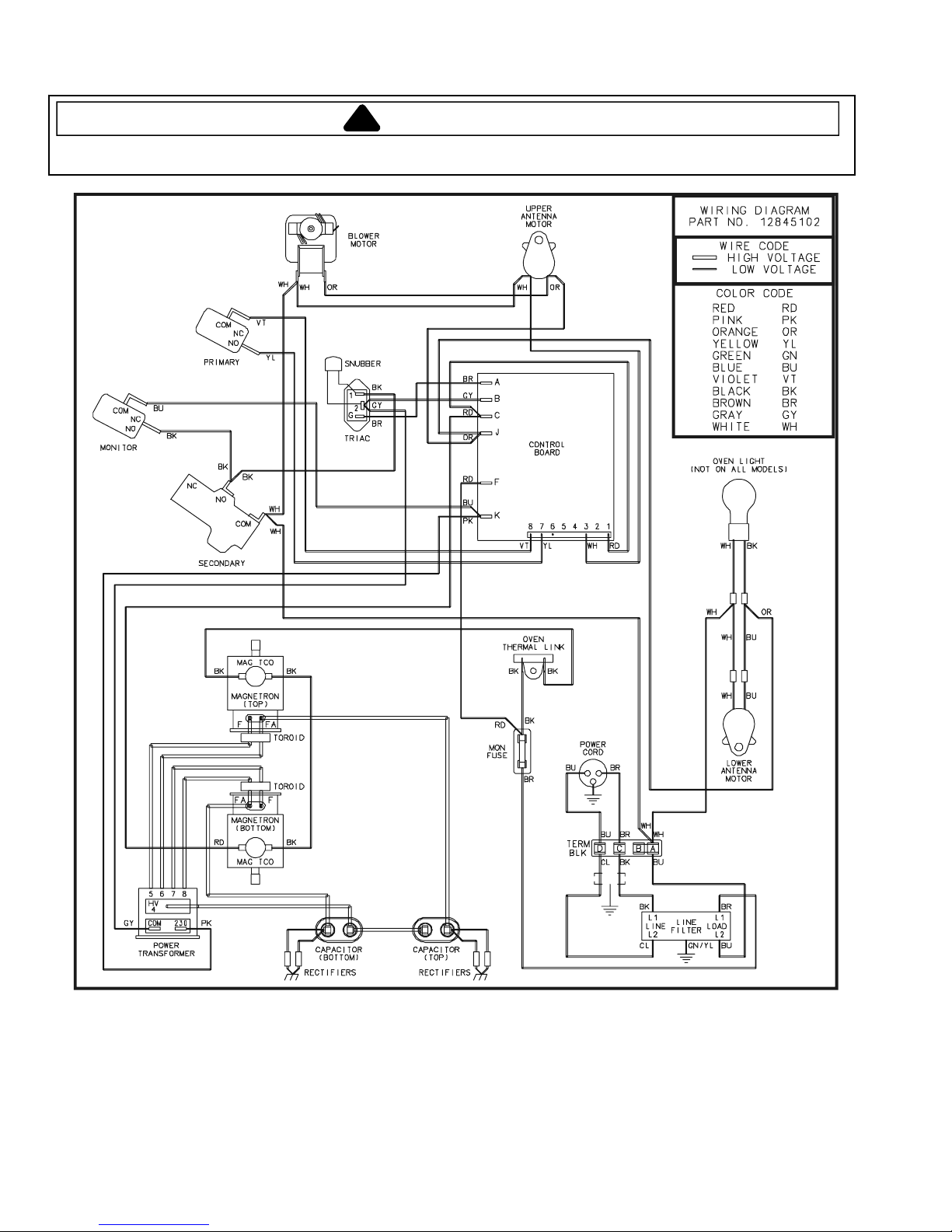
Wiring and Schematic Diagrams
!
To avoid risk of electrical shock, personal injury, or death, disconnect power to oven and discharge capacitor
before servicing, unless testing requires power.
WARNING
HDC5142 UHDC5142
DEC14E2 UC14E2
HDC5182 UHDC5182
DEC18E2 UC18E2
16027612 November 2006
12845102
8
©2006 Maytag Services
Page 9

Wiring and Schematic Diagrams
!
To avoid risk of electrical shock, personal injury, or death, disconnect power to oven and discharge capacitor
before servicing, unless testing requires power.
WARNING
HDC5142 UHDC5142
DEC14E2 UC14E2
HDC5182 UHDC5182
DEC18E2 UC18E2
November 2006 16027612
©2006 Maytag Services
12845102
DANGER
!
HIGH VOLTAGE
9
 Loading...