

Amana SZD20MPE-P1120204WE Owner’s Manual

nl iiiii ilnll II I I IIIIII
_ana_ 24" Deep
Side-By-Side Built-In Refrigerator
Use & Care Manual
i,l,i , ,HI '"n" ,,,,,,,,,,,,,,,i
_.,aea 20

Welcome to
the Amana Family
Your purchase of an Amana refrig-
erator/freezer--a household
appliance known for its quality and
reliability--is sincerely appreciated by
Amana Refrigeration, Inc. Your total
satisfaction with this new product is
extremely important to us, and this
Use and Care Manual will aid you in
understanding the operation of your
new appliance.
Each product is thoroughly tested
and checked at the factory. Once in
your home, you may want to make a
few simple adjustments of control set-
tings, etc. to tailor your new unit to
your own individual requirements.
These adjustments are easily made
following the instructions in this
manual.
Should your new unit ever require
service, certain product information
will aid in obtaining service faster! For
your convenience and protection,
please record this information in the
box at right and retain this booklet for
future reference.
The Registration Card in the packet
with the manual should be filled out
and returned to Amana Refrigera-
tion, Inc.
Record in the space below
the information found on the
nameplate of your refriger-
ator. The nameplate is
located on the ceiling of the
refrigerator section. Also,
please retain a copy of your
sales receipt for future
reference should warranty
service be needed.
Serial No,
Model No...........................
Manufacturing No
Date of Purchase
Selling Dealer
, WARNING
Electrical Grounding Instructions--This appliance is equipped with a three-prong (grounding)
plug for your protection against possible shock hazards. Where a two-prong wall receptacle is
encountered, it is the personal responsibility end obligation of the customer to contact a
qualified electrician and have it replaced with a properly grounded three-prong wall receptacle in
accordance with the National Electrical Code (see figure.)
Unit is designed to operate on a separate 103 to 126 V.A.C., 15 amp., 60 cycle line.
DO NOT UNDER ANY CIRCUMSTANCES CUT OR REMOVE THE ROUND
GROUNDING PRONG FROM THE PLUG. "['HE UNIT MUST BE GROUNDED AT
ALL TIMES. DO NOT REMOVE WARNING TAG FROM THE SERVICE CORD.
WARNING o.oo.o,.o.ooo..cL.
DO NOT USE A TWO-PRONG ADAPTER, !1_'; J'
DO NOT USE AN EXTENSION CORD, "OUNDGROU"D="GP_ONG
Contents Page
E_ectricaJWarning ................ 2
Unpacking ...................... 3
Door Handle Removal ............. 3
Door Removal ................... 3
Placement, Door Alignment
and Leveling .................... 5
Door Panel and Dispenser
Trim InstallationInstructions ......... 6
The Ice 'N Water Dispenser ......... 8
General Features ................ 11
2
Setting the Controls .............. 12
Refrigerator Features ............. 13
_LECTRIC.AL PLUG WITH GROUNDING PRONG ELECTRICAL REC_ACLE WITH
Contents Page
Freezer Features .............. 15
Other Features ................. 16
Save Energy ................... 17
Care and Cleaning .............. 18
Non-Use Periods ................ 20
Sounds ....................... 21
Before Calling For Service ......... 22
Amana Asure .................. 23
Amana Toll-Free ................ 23

Unpacking, Door Handle and Door Removal
the sound reducing cone. The drain
CAUTION:
To Avoid The Risk Of Personal
Injury use caution in
unpacking, handling, removing,
instalFing and cleaning atl parts
of product which may have
sharp edges.
pan locating stops prevent the pan
from being installed backwards,
Remove all tape and packing
material from inside the unit.
SPECIAL NOTE: Ifcabinet is
unable to fit through doorway safely,
you may have to remove the door
handles, or door assemblies. Refer
to the following chart and diagrams.
,CAUTiON:
To Avoid The Risk Of Personal
Injury wear protective hand
covering.
Remove a}l tape and packing mate-
rial. To remove tape residue, touch
a portion of the tape to the residue
and lift it off, If adhesive residue still
remains, try cleaning the sticky area
with a clean cloth soaked in mild
dish washing soap, Wipe area
clean, tf the wood base is still
attached, have someone help you
tilt the unit onto its back, placing a
sturdy support underneath. Remove
the mounting bolts from the base
and discard bolts and wood base.
IMPORTANT! DOnot leave the cabi-
net on it's back longer than it takes
to remove the wooden base and do
not connect the power cord until
after al! the inside packing has
been removed and the cabinet has
been leveled for proper operation.
With the unit upright, pull the toe
grille from the bottom front (see
Figure 1) and make sure the defrost
drain pan is located underneath the
defrost water drain tube. Two drain
pan side supports (attached to the
cabinet bottom) keep the pan in the
proper location, to make the auto-
matic defrost drain water drop on
To Remove Door Handles
1. Remove screws with a phillips
screwdriver from top of handle
(end cap). (See Figure 2.)
2. Remove end cap,
3. Remove screw from bottom end
cap. (Goes into doer.) Note:
Screws are in at an angle -- do
not scratch handle edge.
4. Pull out vinyl decorator strip by
pulling straight up.
5. Remove screws retaining handle.
6. Handles will easily fall away,
To Remove The Door Assemblies
NOTE: If unit is already in-
stalled slide unit out from
cabinetry first.
t, CAUTION
To Avoid The Risk Of Personal
injuryfirst tape the top of doors for
safety after removing top door
trim. (See Figure 2A)
2, Remove the 3 screws from the
top of the aluminum extruded
trim (See Figure 2).
3. Slide out trim from under end cap.
TO REMOVE THE DOORS
CAUTION:
To Avoid Personal Injury,
securely hold onto the door
handles while removing screws.
PHILLIPS
SCREW-
DRIVER
END CAP
TOP OF
CABINET
TRiM
.................,y
FIGURE 2A
Located Bottom Right Side, , ,,n_,,,,,,
-- 3
FIGURE 1
TOP OF FREEZER DOOR
FIGURE 2

Door Removal
, ILCAUTION:
To Avoid The Risk Of Personal
Injury Or Property Damage
have two people remove the
door, One to hold the door and
one to remove the safety tape,
and help with the tools,
4, Remove the top hinge covers
(see Figure 3).
FIGURE 3
[ CAUTION
ToAvoid Electrical Shock or Death
Disconnect the Power Cord,
5. Mark around the upper hinge
brackets with a pencil to locate
them for reassembly (see Figure
3A).
TOP HINGE PLATE
O}SCONNECT WATER TU_
R_:MOV_ THE TUB_
CLAMp SCR_'W
REMOVE TH_ TUB_
__LAMP
WArE !
1UBE LOOSEN THIS p_.AgTIC UNION
_TTO_I OF FR_EZE_I OOOR
A_IO pt_LL THE TUBE
FIGURE 5
8. Remove the upper door hinges,
(3) screws per upper hinge (see
Figure 6).
r_UT
DRIVER
k
CRITICAL:
H_NG_
B_GKE _
GROUND
WIRES
I FIGURE 6
g. The freezer door water line will
thread through the bottom hinge,
lift the door off carefully (see
Figure 7).
P
FIGURE 3A
J WARNING:
To Avoid The Risk Of Electrical
Shock, Personal Injury or
Death: DISCONNECT the
power cord BEFORE removing
the top hinge,
6, Disconnect top hinge freezer
door wires (see Figure 4),
10.
Remove the refrigerator door
assemblies by lifting off the
bottom hinge pins. Note: At this
point the refrigerator may fit
2/:2
LOWE_H_E S_C_ET FIGURE 7
through the doorway. If not,
proceed to steps 11 and 12.
11. Mark around the lower hinge
brackets (see Figure 8),
7. Disconnect freezer door bottom
hinge water line by loosening
the 1/4"O.D. plastic tube union nut
(see Figure 5).
,,,,,
4
12_Remove the lower hinge bracket
screws. (2) screws per lower
hinge,
To install the door assemblies,
assemble in reverse order.
• WATE_ I YklllE U_4;ON
FIGURE 8

Placement, Door Alignment and Leveling
Placement
On some counter tops there is a 1"
overhang. If this is the case, the
front corners of the counter top
must be trimmed off at a 45° angle
for the refrigerator and freezer door
clearance (see Figure 9), Tobuild-in
your refrigerator a Perimeter Trim Kit
is available from your dealer at an
additional cost.
A recessed electrical outlet installed
on the back wallallows for a built-in
installation of your refrigerator,
Suggested height requirement for
recessed electrical outlet is 3 to 4 ft.
from floor.
To build in your refrigerator with
other options, such as wood or
laminate consult with a local kitchen
designer.
CAUTION:
To Avoid Property Damage to
soft vinyl flooring follow the
floor product manufacturer's
recommendations when
installing or moving the
refrigerator.
ELE(_fR_L 1
24 _
TOP VIEW OF AMANA
20 CU* FT, REFRIGERATOR
.........½
!" OVERHANG_
Leveling
Install the refrigerator on a solid
floor that is strong enough to
support the combined weight of the
unit, approximately 320 Ibs,; and the
food, maximum of 625 Ibs, with an
approximate combined weight of
945 Ibs.
The refrigerator must be level from
side to side, front to back to insure
complete door closing and proper
Door Alignment
The doors on this refrigerator were
aligned at the factory. Once the
refrigerator is properly leveled, the
doors will be aligned. If further
adjustment is required, please follow
the steps below.
1. Before checking alignment, open
and close both doors to insure
they are resting on the bottom
bearings,
2. Check alignment of doors at
TOP CENTER. See Figure 11, If
doors are aligned, go to step 4,
FREEZER DOOR / TRIM
TRIM
i
REFRIGERATOR DOOR
i
/
231/t.
24" 1
_L _..J
\ 1"O'VE_HANG
ice making. This allows doors to
close firmly, Your refrigerator is
equipped with front and rear
leveling feet. Adjust the wheels or
leveling feet to level the refrigerator.
To raise, turn screw or leveling feet
clockwise, To lower, turn counter-
clockwise. See Figure 10. Improper
leveling wilt cause water spills and
uneven ice cube size,
3, If doors are not aligned:
4. If one of the front rollers is not
TOP OF
COUNTER
FIGURE
A_
Lower the front roller (turn
___lI_ _ ,,,,,.,_
Rear Leveling i
Screw _
the screw clockwise one turn
at a time) on the side of the
refrigerator which has the
lower door. See Figure 10.
B, Open and close both doors.
C. Recheck alignment.
D. If doors are not aligned
repeat steps A through C.
touching the floor (refrigerator
will rock), lower that roller only
enough to contact the floor.
FIGURE 10
FIGURE 11
5

Door Panel and
Dispenser Trim Installation Instructions
Tools Needed -- Standard Straight
Screwdriver, Phillips Screwdriver,
1/4" Hex Nut Driver and Tightly
Fitted Gloves
1. Remove screw from both top
and bottom handle end cap. See
Figure 12 and 13.
i
Bottom
End Cap
FIGURE 12 FIGURE 13
2. Remove end caps and place
aside until needed. See
Figure 14.
5, Remove screws retaining handle,
See Figure 16, Handles will
easily fall away. If you have a
conventional model skip to step
number 10, If you have a
dispensing model proceed with
step number 6.
FIGURE 16
6. DispenserTrim parts are shipped
separately and are located in
the top crisper drawer in the
refrigerator compartment.
(Dispensing Modets Oniy.)
FIGURE 14
3. Slide out gray vinyl decorator
strip located in the inset of the
handle. See Figure 15.
FIGURE 15
, CAUTION:
To Avoid Personal Injury
securely hold onto the door
handles while removing screws.
4. NOTE: Screws are in at an
angle -- DO NOT scratch
handle edge.
FIGURE 17
These trim pieces are designed
to fit above AND below the
dispenser and provide a groove
for panel installation. See
Figure 17. (Dispensing Models
Only.)
.
To install the decorator trim
gently slide the trim into the
groove above the dispenser as
shown in Figure 17. (Dispensing
Models Only.)
g.
To install the 2nd piece of trim
below the dispenser follow the
directions in step 8. See
Figure 17 for placement.
(Dispensing Models Only.)
CAUTION:
To Avoid Property Damage
take care not to tilt or start
panel at an angle, to do so _yill
cause panel to jam and may
damage the trim.
6
m

Door Panel and
Dispenser Trim Installation Instruction (cont.)
10. Gently insert the decorator panel
into grooves and slide EVENLY
until the panel is securely in
place.
11. To replace handles reverse the
procedures above. Numbers 1
through 5.
Decorator Doors
Tools Needed -- Standard Straight
Screwdriver and Tightly Fitted Gloves
The door fronts are to be decorated
with panels to accent your kitchen
decor. Models are equipped with
metal door edge trim kits required
to do this.
Dimensions
ICE 'N WATER SXS MODEL
(ALL OIMENSIONS IN tNCHES)
?INCLUDES DOOR TRIM
The basic %" trim kit is attached to
the door edges and hold lt4"-thick
panels. A _'16"filler such as card-
board is requiredfor 1h6"panel. Ask
your Amana dealer about panel
availability, or you may supply your
own panels.
For your convenience the panel
dimensions are listed below:
SBI20
Freezer Door 14"x 631A6"
Refrigerator Door 19_ x 631/_s"
SBD20
Upper Freezer Door 14"x 18¾"
Lower Freezer Door 14"x 3111/ts"
Refrigerator Door 19%"x 631A6"
5 s/
CONVENTIONAL SXS MODEL
1INCLUDESDOORTRIM
J t t
e C
I
O----I
O r hi Topoi
Do | 1[ I Cabinet
Handle _ pp- I 1%"
B C
]
T-
I
"A.... B.... C" OC*BAC;KOC"BACK
CAPANETFP.ZgOOR REFDOOR TO TO
MO_L WIDTH OPEN_ OPEN90_ HANDLE FK4)N1
35#4 3_ 4_ Z/_ 23W
*Os'teCale
"D.... E"
7
The Ice 'N Water Dispenser
Connect the Ice 'N Water
System To Cold Water
Supply,
Refer to the instructions on the
back of the cabinet.
, CAUTION
Toavoid cross threading and water
leaks, turn the water tube fittings by
hand several times before tightening
with wrenches, DO NOT OVER-
TIGHTEN. Also be sure to double
check for water leaks after turning on
the water pressure to the refrigerato_
The automatic ice 'N Water,_
Dispensing Compartment
The Amana Ice 'N Water Dispensing
Compartment will give you carefree
use with minimal attention.
Automatic Nite Lite
This isan optional feature that
comeson automaticallywhen
it's dark, If you wouldprefer
not to use the nite litefeature,
there is an on/offswitch just
above the ice and waterdis-
pensing bars, Push this switch
in once to turn off the nite lite,
Nite Lite Bulb
Replacement
Should the nite lite bulb ever
need to be replaced, it is
located just above the water
dispenser bar. Replace with a
120 volt, 6 watt Sylvania 6S6
bulb or order from your Amana
Service Dept., part number
M0360001.
Do not add ice to ice bin.
Do not try to speed ice dispensing
by adding cubes of ice that you
may have purchased or made in
some other way. The unit has been
"matched" to the automatic ice
maker and will not operate properly
with different shaped or sized cubes.
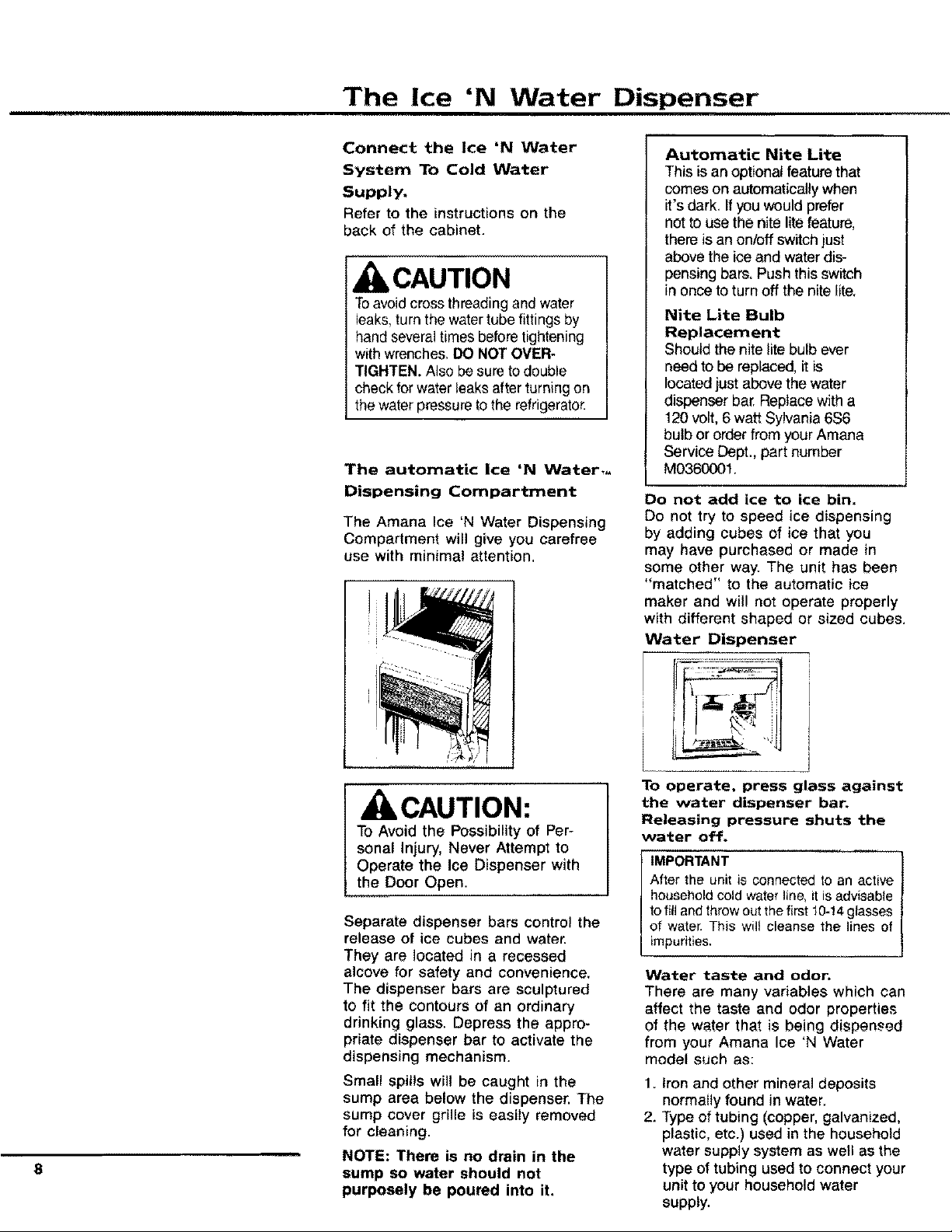
Water Dispenser
To operate, press glass against
CAUTION:
To Avoid the Possibility of Per-
sonal Injury, Never Attempt to
Operate the Ice Dispenser with
the Door Open.
Separate dispenser bars control the
release of ice cubes and water.
They are located in a recessed
alcove for safety and convenience,
The dispenser bars are sculptured
to fit the contours of an ordinary
drinking glass. Depress the appro-
priate dispenser bar to activate the
dispensing mechanism.
Small spills will be caught in the
sump area below the dispenser. The
sump cover grille is easily removed
for cleaning.
8
NOTE: There is no drain in the
sump so water should not
purposely be poured into it,
the water dispenser bar.
Releasing pressure shuts the
water off.
IMPORTANT
After the unit is connected to an active
household cold water line, it is advisable
to fill and throw out the first 10-14 glasses
of water. This wilt cleanse the lines of
impurities,
Water taste and odor.
There are many variables which can
affect the taste and odor properties
of the water that is being dispensed
from your Amana Ice 'N Water
model such as:
1. Iron and other mineral deposits
normally found in water.
2. Type of tubing (copper, galvanized,
plastic, etc.) used in the household
water supply system as well as the
type of tubing used to connect your
unit to your household water
supply.
 Loading...