

RSW2TK27
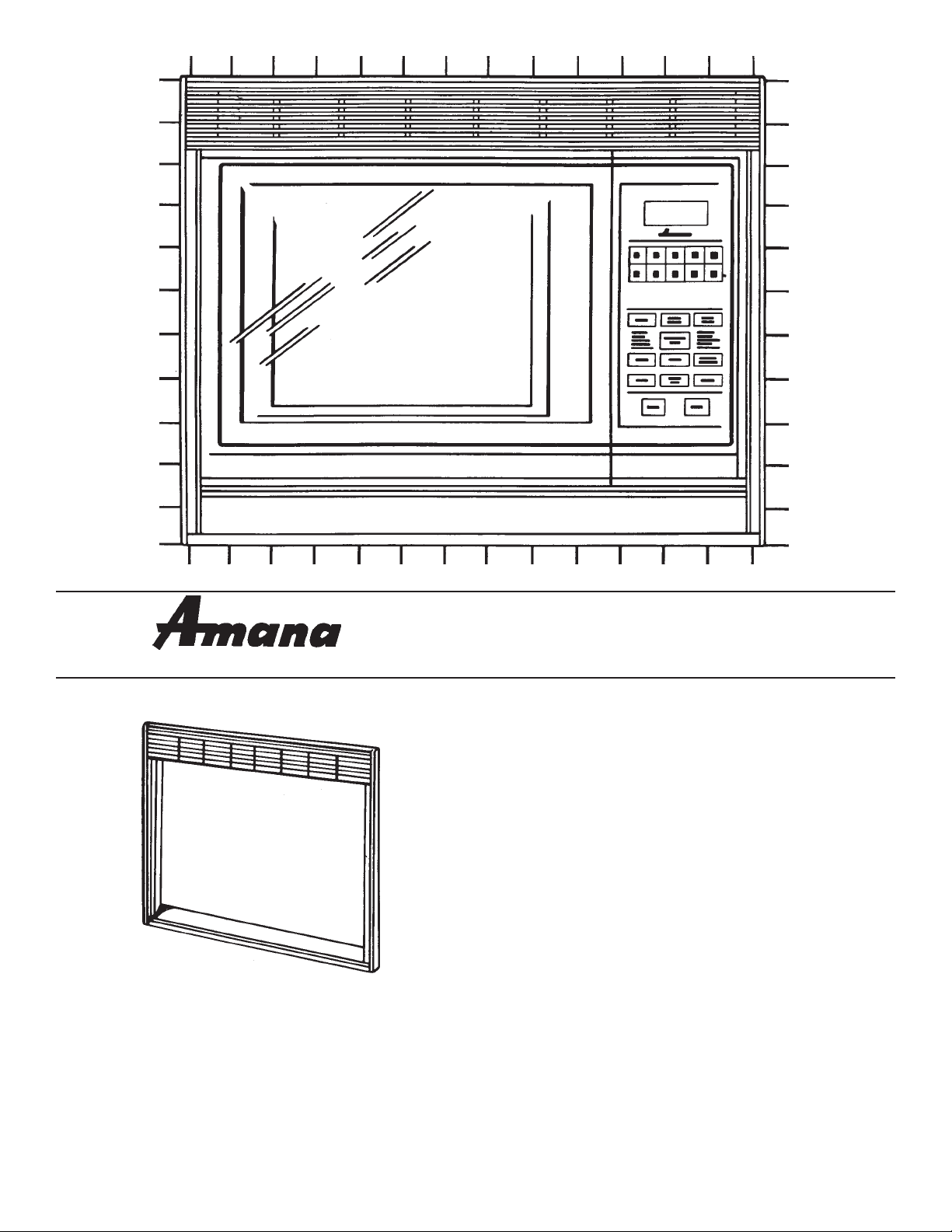
assembled trim
frame
Microwave Oven
â
Installation Instructions
RSW2TK27
Built-In Trim Kit
for 60 Hz 'RSW' or 'RW" Model Series
Read all instructions before starting installation.
Important-Save these instructions for electrical
inspector's use.
1
2
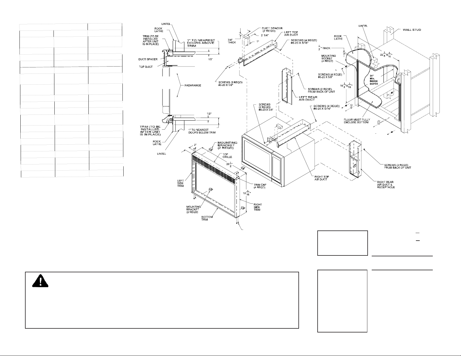
Parts of Kit
Item
Qty
Part No.
Wide Rear Duct (with
electrical cord)
1
D7723701
Wide Top Duct
1
D7723706
Narrow Rear Duct
1
D7723702
Narrow Top Duct
1
D7723707
Stop Bracket
2
A3277303
Short Gray Sheet
Metal Screws
8
M0211516
Long Gray Sheet
Metal Screws
10
M0211519
Mounting S ocke t
4
10804601
Mounting B rac ket
2
10804701
Mounting B rac ket
2
10804702
Flat Head Chrome
Screws
8
M0213517
Template Mounting
1
10808701
Duct Spacer
2
10352601
Trim Cap-Left
2
10331402
Trim Cap-Right
2
10327102
Top Gri lle
1
10326708
Bottom Trim
1
10805503
Left Side Trim
1
10805603
Right Si de Tri m
1
10805703
Caution
If installing this kit above a wall oven:
SCREWS (8 REQD)
#6-20 X 3/4"
FLAT HEAD
Due to large differences in wall oven designs, the only acceptable combination is a
"RSW" or "RW" model series microwave oven above an Amana AO24 or AO27 wall
oven. To protect against excessive heat from the wall oven below it, bottom of
microwave oven cutout must have a full floor.
If not installing above a wall oven, make
cutout at any height convenient to user.
Cutout dimensions:
+ 1/16"
Microwave
Oven Cutout
Height 16 1/2"
Width 22 1/8" + 1/16"
Depth 20" minimum.
minimum distance between cutouts is 1-1/4"
Wall Oven
Cutout
(Consult
Appropriate
Instructions)
«

120V-15AMP
GROUNDING INSTRUCTIONS
This appliance MUST be grounded. In the event of an electrical short
circuit, grounding reduces the risk of electric shock by providing an
escape wire for the electric current. This appliance is equipped with a
cord having a grounding wire with a grounding plug. The plug must be
plugged into an outlet that is properly installed and grounded. DO NOT
use a two-prong adapter.
WARNING - IMPROPER USE OF THE GROUNDING PLUG CAN
RESULT IN A RISK OF ELECTRIC SHOCK OR DEATH.
Consult a qualified electrician or serviceman if the grounding instructions
are not completely understood, or if doubt exists as to whether the
appliance is properly grounded. It is the installer's responsibility to
ensure that the circuit and receptacle are grounded and polarized in
accordance with local codes and the National Electric Code. Do not use
an extension cord.
This kit should be plugged into a separate 120 volt, 15 amp, 60 hertz
circuit. This kit is not to be used on a 50 hertz circuit. When a
microwave oven is on a circuit with other appliances, an increase in
cooking times may be required and fuses can be blown.
Power Cord
A short power cord is provided to reduce the risks resulting from becoming entangled in or tripping over a
longer cord.
Caution: Installation above wall ovens
This built-in kit is designed to be installed above an Amana conventional electric wall oven
only (see note on page 2). Other brands of wall ovens may not provide sufficient insulation to
isolate the microwave oven from excessive heat. Various components, including touch
controls (if oven has this feature), may fail to function properly.
Materials Needed (Not Supplied)
Phillips and standard screwdrivers
120 volt, 15 amp, 60 Hz electrical receptacle
switchbox and cover plate
Installation
1. Prepare wall cutout according to dimensions
shown on page 2. Route proper wiring, as noted
in the grounding instructions above, to cutout.
Electrical receptacle may be surface-mounted or
flush-mounted anywhere 19 1/2" to 24" from the
front of the cutout.
2. Match and assemble the top and rear ducts.
Secure with the short gray sheet metal screws.
(Rear ducts fit inside top ducts.)
3

3. Remove the five screws from the edge of outer
case at back of oven. Do not remove any other
screws!
4. Position duct assemblies on oven back and top
(wide duct on the left). Attach with screws just
removed from oven.
5. Before installing wide duct assembly, plug oven
into electrical receptacle in duct housing. Loop
oven cord and push it into duct as shown. Do
not trap cord between duct and back of oven.
7. Plug duct cord into receptacle in cutout. Slide
oven in until duct spacers contact wall above
cutout. Position stop brackets below oven near
front feet and secure to wall with long gray sheet
metal screws.
7. Slide plastic mounting brackets into top and
bottom trim pieces.
8. Assemble trim frame by inserting trim caps into
left and right side trims, then aligning holes in
top grille and bottom trim with channels in side
trims. Secure with flat head chrome screws.
6. Attach duct spacers to ducts using long gray
sheet metal screws. Center spacers on ducts as
shown on page 2.
Save these instructions for electrical inspector's use.
Part No. 10686002
Printed in U.S.A.
9. Temporarily slip assembled frame over oven
(wide grille at top). Check alignment of trim and
oven to be sure everything is lined up correctly.
10. Remove trim frame and set aside.
11. Use mounting template to locate 4 screws and
attach mounting sockets to wall.
12. Line up mounting brackets in the frame with
mounting sockets. Snap the frame onto sockets.
ã1994 Amana Refrigeration, Inc.
Amana, Iowa 52204
4
 Loading...