

Amana PBC093G00CC Installation manual
THROUGH THE W ALL
ROOM AIR CONDITIONER
WITH OPTIONAL ELECTRIC HEAT
INSTALLATION INSTRUCTIONS
RECOGNIZE THIS SYMBOL AS A SAFETY PRECAUTION.
ATTENTION INSTALLING PERSONNEL
As a professional installer you have an obligation to know the product better than the customer. This includes all
safety precautions and related items.
Prior to actual installation, thoroughly familiarize yourself with this Instruction Manual. Pay special attention to all
safety warnings. Often during installation or repair it is possible to place yourself in a position which is more
hazardous than when the unit is in operation.
Remember, it is your responsibility to install the product safely and to know it well enough to be able to instruct a
customer in its safe use.
Safety is a matter of common sense...a matter of thinking before acting. Most dealers have a list of specific good
safety practices...follow them.
The precautions listed in this Installation Manual are intended as supplemental to existing practices. However, if
there is a direct conflict between existing practices and the content of this manual, the precautions listed here take
precedence.
is a registered trademark of Maytag Corporation or its related companies and is used under
license to Goodman Company, L.P., Houston, TX. All rights reserved.
IO-749B
July 2013
www.amana-ptac.com
© 2010, 2012-2013 Goodman Company, L.P.
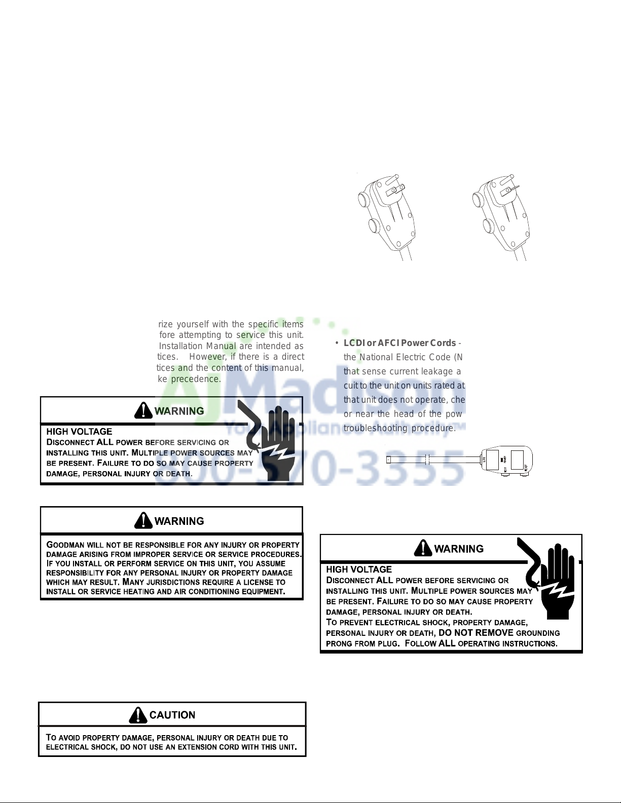
TABLE OF CONTENTS
UNIT FEATURES
Important Note to Homeowner .................................................... 2
Important Note to Servicer........................................................... 2
Operating Instructions ................................................................. 2
Unit Features ................................................................................ 2
Installation Instructions ............................................................... 3
Wiring........................................................................................... 6
Air Conditioner Features ............................................................. 7
Additional Information ................................................................. 8
Normal Operating Sounds and Conditions ................................ 9
Obtaining Service ........................................................................ 9
Consumer Warranty .................................................................. 10
Commercial Warranty ................................................................11
IMPORTANT NOTE TO THE HOMEOWNER
This manual is to be used by qualified, professionally trained HVAC
technicians only. Goodman does not assume any responsibility
for property damage or personal injury for improper service procedures or services performed by an unqualified person.
IMPORTANT NOTE TO THE SERVICER
Read this manual and familiarize yourself with the specific items
which must be adhered to before attempting to service this unit.
The precautions listed in this Installation Manual are intended as
supplemental to existing practices. However, if there is a direct
conflict between existing practices and the content of this manual,
the precautions listed here take precedence.
This unit has many features which are different than those found
on conventional units. The servicer must be familiar with these
features in order to properly service the unit.
Check the data specification plate and ensure the proper voltage
and current rating is available for the type power plug on the unit.
DO NOT REMOVE THE GROUNDING PRONG FROM THE POWER
CORD. Note the types of acceptable plugs in Figure 1.
Refer to the data serial plate for electrical requirements.
120V
15 Amp
230V
20 Amp
Figure 1
• LCDI or AFCI Power Cords - Underwriters Laboratories and
the National Electric Code (NEC) now require power cords
that sense current leakage and can open the electrical circuit to the unit on units rated at 250 volts or less. In the event
that unit does not operate, check the reset button located on
or near the head of the power cord as part of the normal
troubleshooting procedure.
OPERATING INSTRUCTIONS
Check the data specification plate and ensure the proper voltage
and current rating is available for the type power plug on the unit.
DO NOT REMOVE THE GROUNDING PRONG FROM THE POWER
CORD. Note the types of acceptable plugs on the following figure.
Refer to the data serial plate for electrical requirements.
LCDI Power Cord
Figure 2
VOLTAGE MEASUREMENTS
Before connecting the unit, measure the supply voltage. Voltage
must fall within the voltage utilization range given in the following
table.
2
Operating Voltage
Unit Voltage
Voltage Utili zat ion Ra ng e
Rating Min imum Maximum
230/280 187 253
115 103 126
INSTALLATION INSTRUCTIONS
To ensure that the unit operates safely and efficiently, it must be
installed, operated, and maintained according to these installation and operating instructions and all local codes and ordinances,
or, in their absence, with the latest edition of the National Electrical
Code. The proper installation of this unit is described in the following sections. Following the steps in the order presented should
ensure proper installation.
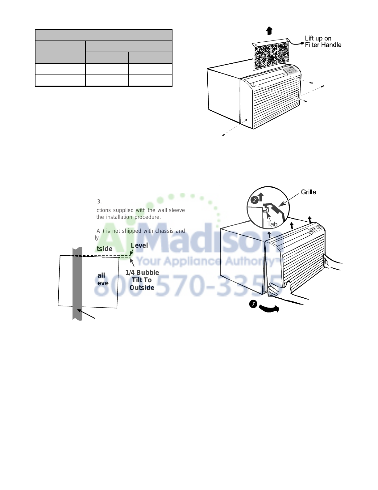
SLEEVE INST ALLA TION
In order for condensate water to drain properly inside the unit, the
sleeve must be installed properly:
• Level from right to left.
• A slight downward pitch from the indoor side to the outdoor
side as shown in Figure 3.
Refer to the Installation Instructions supplied with the wall sleeve
for a complete description of the installation procedure.
Figure A
The front grille can be removed for more thorough cleaning or to
make the model and serial numbers accessible. To remove, pull
the filter out and remove the four grille screws.
NOTE: Wall sleeve (PBWS01A ) is not shipped with chassis and
must be purchased separately.
OutsideInside
Wall
Sleeve
Level
1/4 Bubble
Tilt To
Outside
Outside
Wall
Figure 3
CHASSIS INST ALLATION
1. Remove front grille. See Figure A.
Pull the grille out from the bottom and lift up from the tabs on the
top of the case.
2. Remove the grounding screw and wire next to the grounding
symbol on right side of chassis control panel (Figure 3). Attach other end of ground wire to the hole in the bottom right
side of the sleeve with #8 x 3/8” blunt point sheet metal screw .
The hole on the sleeve is indicated by grounding symbol on
the sleeve. Slide chassis part of the way into the sleeve and
reattach the ground wire back to the hole on the right side on
the control panel area next to the grounding symbol.
3
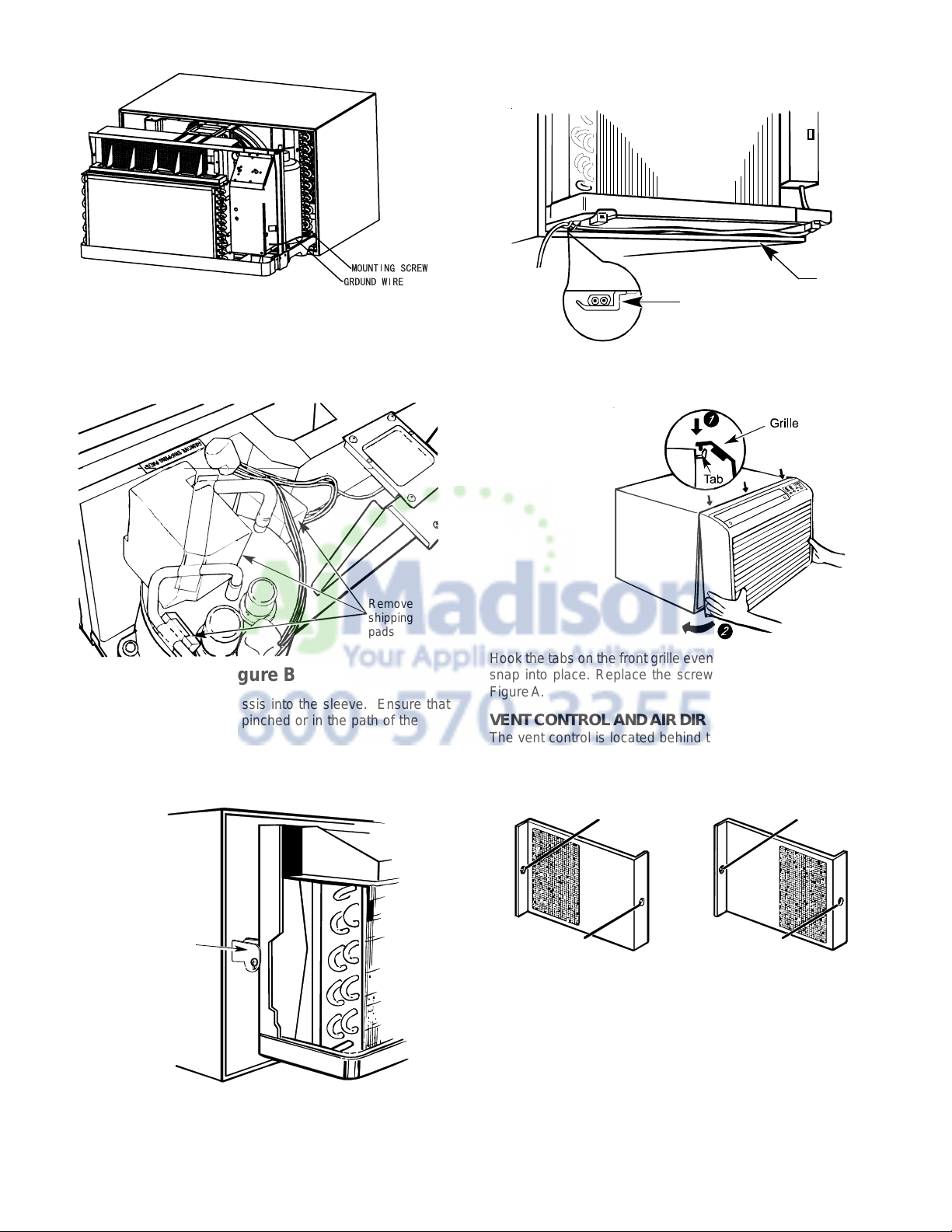
Figure 3
6. If outlet is on the left side of the unit, route power cord as
shown in Figure D.
Power
Clamp
Cord
3. Remove shipping pads inside air conditioner next to
compressor. (See Figure B.)
Remove
shipping
pads
Figure B
4. Carefully slide the chassis into the sleeve. Ensure that
the ground wire is not pinched or in the path of the
condenser fan.
5. Loosen locking plate screw and rotate tab with tab
behind wall case flange (See Figure C) then tighten
locking plate screw.
Figure D
To replace front grille:
Hook the tabs on the front grille even with the tabs on the case and
snap into place. Replace the screws and filter. Refer to Page 3,
Figure A.
VENT CONTROL AND AIR DIRECTION (See Figure E)
The vent control is located behind the front grille on the right
side of the air discharge area. When set at CLOSE only the air
inside the room will be circulated and conditioned. When set at
OPEN, some inside air is exhausted outside.
Locating
Hole
Locating
Hole
Locking
Plate
Figure C
Screw Hole
OPEN posi t io n
(Mesh end toward back)
To open or close the vent:
1. Remove the front grille.
2. Remove the vent card screw.
4
Screw Hole
CLOSE position
(Mesh end toward front)
Figure E
 Loading...