

Page 1
Amana Technical Information Electric Range
ARR6400 P1142670N, Pi143415N, P1143432N, P1143457N, P1143607N, P1143640N,
P1143653N, P1143674N
ART6510 P1143460N, P1143469N, P1143482N, P1143611N, P1143630N, P1143657N
• Due to possibilityof personal injuryor property damage, always contact an authorized technician for servicing or
repair of this unit.
• This technical sheet replaces RT2320003 Rev. 8.
• Refer to Service Manual RS2320004 for detailed installation, operating, testing, troubleshooting, and disassembly
instructions.
• Refer to Parts Manual RP2320040 for part number information.
CAUTION
MI safety information must be followed as provided in Service Manual RS2320004.
[ WARNING
To avoid risk of electrical shock, personal injury, or death, disconnect power to oven before servicing, unless
testing requires it.
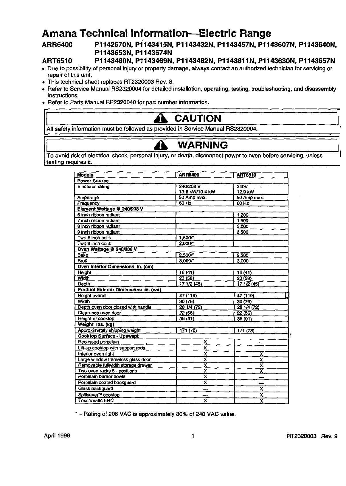
Models I ARR6400 I ART6510
I Power Source
Electrical rating 240/208 V 240V
Amperage
Frequency
Element Wattage @ 240/208 v
6 inch ribbon radiant
7 inch ribbon radiant
8 inch ribbon radiant
9 inch ribbon radiant
Two 6 inch coils
Two 8 inch coils
Oven Wattage @ 240/208 V
Bake
Broil
Oven Interior ,Dimensions In. (cm)
Height
Width
Depth
Product Exterior Dimensions In. (cm)
Height overall
Width
Depth oven door dosed with handle "
Clearance oven door
Height of cooktop
Weight Ibs. (kg)
Approximately shipping wel'ght
Cook'top Surface - Upswept
Recessed porcelain
Lilt-up cooktop with support rods
Interior oven light
La_e window frameless glass door
Removable fullwidth storage drawer
Two oven racks 5 - positions
Porcelain burner bowie
Porcelain coated baek_luard
Glass back_luard
S_llsaver TM cooktop
Touchmatic ERC
13.8 kW/10.4 kW 12,9 kW
50 Amp max. 50 Amp max.
60Hz 60Hz
1,200
t r500
2_000
2,500
1,500/*
2,600/*
2t500/* 2r500
3000/* 3r000
16 (41} 16 (41)
2"3(58) 23 (58)
t7 1/2 (45) 17 1/2 (45)
47(119) 47(110)
s0_76) 30(76)
20 1/4{72) 28 1/4('/2)
22(56) 22(56)
36(91) 36(91)
171 (78) 171 _78)
X
X
x
X
x
X
X
X
X
X
X
X
X
X"
X
X
I
!
II
"- Rating of 208 VAC is approximately 80% of 240 VAC value.
April 1999 1 RT2320003 Rev. 9
Page 2
Component Testing Procedures
To avoid risk of electrical shock, personal injury, or death, disconnect power to oven before servicing, unless
f WARNING
testing requires it.
'1
nlustration
31823701
31722801
301491
31734606--2600 W 6" and 8"
31730101 Coilsurface terminal Remove element and turn surface
31794701-1200 W Ribbon radiant Remove one wire lead from element Continuity,if not replace.
31794601-1500 W elements and measure resistanceof the 1200W: 45 to 51
31794501-2000 W element, t50OW: 36 to 41
31794801-2500 W 200OW: 27 to 31
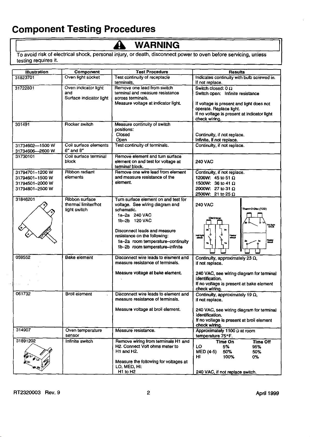
31846201
Component
Oven light socket
Oven indicator light
and
Surface indicator light
Rocker switch
block element on and test for voltage at 240 VAC
Ribbon surface
thermal limiter/hot
lightswitch
Test continuityof receptacle
terminals.
Remove one lead from switch
terminal and measure resistance
acrossterminals.
Measure voltage at indicatorlight.
Measure continuityofswitch
positions:
Closed
Open
Test continuityofterminals.
terminal block.
Tum surface element on and test for
voltage. See wiring diagram and
schematic.
la-2a 240 VAC
lb-2b 120 VAC
Test Procedure
Results
Indicates continuitywith bulbscrewed in.
If not replace.
Switchclosed: 0
Switchopen: Infinite resistance
]f voltage is present and lightdoes not
operate. Replace light.
If no voltage is present at indicatorlight
checkwidng.
Continuity, if not replace.
Intinife,if notreplace.
Continuity, if notreplace.31734602--1500 W Coil surface elements
2500W: 21 to 25
240 VAC
Etectmv_
059552
061732
314907
31891202
I Bake element
Broil element
Oven temperature
sensor
Infinite switch
Disconnect leads and measure
resistanceon the following:
la-2a roomtemperature-continuity
lb-2b room temperature-infinite
Disconnectwire leads to element and
measure resistance of terminals.
Measure voltage at bake element.
Disconnectwire leads to element and
measure resistance of terminals.
Measure voltage at broilelement.
Measure resistance.
Remove wiring fromterminalsH1 and
H2. Connect Volt ohms meter to
H1 and H2.
Measure the followingfor voltages at
LO, MED, HI:
H1 to H2
Continuity,approximately 23 Q,
ifnot replace.
240 VAC, see wiring diagram forterminal
identification.
Ifno voltage is presentat bake element
check widng.
Continuity, approximately 19 £_,
if not replace.
240 VAC, see wiringdiagram for terminal
identification.
If novoltage is present at broilelement
checkwidng.
Approximately1100 _ at room
temperature 75°F.
Time On Time Off
LO 5% 95%
MED (4-5) 50% 50%
HI 100% 0%
240 VAC, if notreplace switch.
RT2320003 Rev. 9 2 Apd11999
Page 3
Component Testing Information
To avoid risk of electrical shock, personal injury, or death, diSconnect power to oven before servicing, unless
I I WARNING
testing requires iL
I
Illustration
053584
31715201--LH
31715202--RH
065780
305797
Component Test Procedure Results
Control limit Normally Closed
Verify proper operation.
Closed 245°F Continuity
Open 275°F Infinite
If open at roomtemperature, replace.
Hinge
Door lock switch
Door plungerswitch
Carefully open the hinge fully, and
insert a wooden dowelor screwdriver
bitinto opening.
Remove top and bottom screws
: securing hinge.
Slide hinge top towards rear of unit
and guide hinge out throughframe
opening or storage drawer.
Switch connectionin following
positions:
Unlooked
Looked
;et ERC to Clean
Remove switchfrom unit and measure
the following points:
C-NC
C NO
I 4_ CAUTION II
Do notplace hands in hinge area when
Ovendooris removed. Hinge can snap
closed and pinch hands or fingers.
COM-NO=Open, COM-NC=Closed
COM-NO=Clceed, COM-NC--Open
Lock LED should flash
LookLED and Oven LED should
illuminate,If LockLED does not
illuminate,check switch and widng.
Plunger ininfinite, Plunger out continuity.
Plunger incontinuity, Plunger out infinite.
I
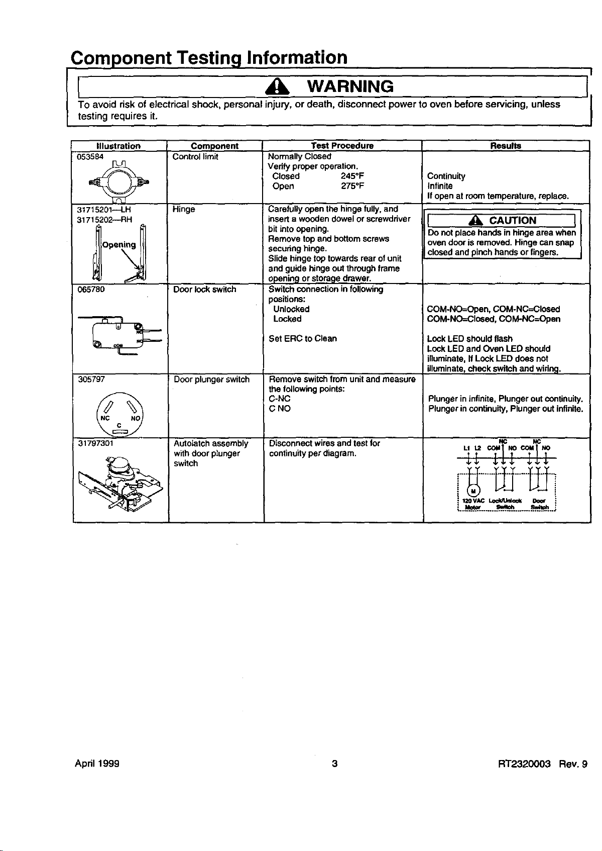
31797301
Autotatch assembly
withdoor plunger
switch
Disconnect wires and test for
continuityperdiagram
NC NC
__, ,_
,:....a_H.__.....___.o_ _.. ;
April 1999 3 RT2320003 Rev 9
Page 4

Component Testing Procedures
To avoid risk of electrical shock, personal injury, or death, disconnect power to oven before servicing, unless
I L WARNING
testing requires it.
IllustraUon
ERC3 Controlled
ERC3 Controlled
ERC3 Controlled
ERC3 Controlled
Component
ERC3 - Touchmatic
electronic range
control
Oven temperature
adjustment
Twelve hour off
Child lock out
Drive requirements
Based on a 60
second cycle.
F1---Shorted pad button.
F2---Oven cavity over temperature.
F3---Open circuitinoven temperature
sensor circuit.
F4_Shorted circuitin oven
temperature circuit.
F5--Defective watchdogcircuitin
contmL
F"/-_Failure of door lockswitchsensing
with door looked.
Fg--Failure of door lockswitching
sensingwith door unlocked.
DOOR--Look status is not sensed
within 20 seconds of energizing door
lookrelay.
Push BAKE pad.
Push SLEWpad until an oven
temperature greaterthan 500°F
displays.
I Immediately pushand hold BAKEpad
until"00" displays,approximately 5
seconds.
To decrease oventeroperatara (for a
cooler oven), Push SLEWpad until
negative numbersappear, Oven can be
adjustedfrom -05° to -35° ower. To
avoid over adjustingoven move
temperature -5° each time.
To increase oventemperature (for a
warmer oven), Push SLEWped until
positive numbersappear. Oven can be
adjusted from 5" to 35 ° higher. To avoid
over adjusting oven move temperature
5° each time.
Push OVEN CANCEL button.
Temperature adjustment willbe
retained even througha powerfailure.
Controlwillautomaticallycancel any
cookingoperationand remove all relay
ddves 12 hoursafter the last pad touch.
Controlinputfeatures willbe disabled
and display will indicate"OFF", when
BAKE and CLOCK are pushed
simultaneouslyand held for 5 seconds.
Controlwill returnto normal operat on
by repeatingthe procedure.
Bake
Broil
Clean
Stage 1
Stage 2
Lock light
Test Procedure
Results
Verify actuator operation.
Check sensorwidng, sensor, and
temperature limiter,
Check sensor resistanceand wiring.
Check sensor resistanceand widng.
Replace ERC3.
Check latch switchand door motor.
Check latch switchand door motor.
Vedfy operationof door latchswitches.
While increasingor decreasing oven
temperature, this does not affect self-
cleaningtemperature.
100% bake 10°1,broil
0O,_,bake 100% broil HI
0% bake 93% broil 5
0% bake 87% broil 4
0% bake 80% broil 3
0% bake 73% bmil 2
0% bake 57"/,,broil 1
Time controlled15 minutes 0% bake
100% broil.
Time controlled100% bake 10o/obroil.
On at the startof the clean cycle.
Off at approximately 400°F + 25°F.
'1
RT2320003 Rev. 9 4 Apd11999
Page 5

Wiring Diagram and Schematic
To avoid risk of electrical shock, personal injury, or death, disconnect power to oven before servicing, unless
[ WARNING
testing requires it.
I
I[NPERATURE CO. 9BIN 9SOCKET
SENSOR PLUG CAP
Lr SI IlK
B PIN I_C
I LOCK
u J\ $ I L
WB BU \ " I I
RU 2SOCKET
CIR OR
BOON
lATCH $I
VT VT
5TERNCONNECTOR
RELAY CONNECTIONS
(BR) (LI) (BA)
YL 2SOONBAKE
16
CA
ELECTRONICRANGE
CONTROL(E.R,C.)
J4- IOIERN CONNECTOR
OVENHIGHLIMIT
UOO0t
BROtL
_L
NO
OR
SURFAC[ ELEg [BES
R.F. R,R.
K2
12 LI
IOH1 A
IFACE Vl
EOR H
BACKCUARO IUOA NEON
SUHUACEELEKENTS
L,R. L.F.
18 IB 16 I
CA
CA CA Ok C
BU YL
SWITCH
R.R.
16CA BK
MAINTOP
_6CA RD _
_H CBASS]SCNO
10 HASSIS
_GROUNO
L_F_
(,,TG,K'
! El P
SURFACE
BE
LE'T
COLOR COLOR '
REO KO ROUGE
ORANC_O_
YElLO_ Y L JAUN_
GREE_ O_ VEBI
BLUE eu BLEU_U
WOL_) VT v_OlEl
BLACK BK NOIR
Re0H_ e_
NOTES:
I ALLINT[RNALN(RESAR_ 1BGA,)SB "C XLUNLESSOIBER()S[ NOTEO
2 ALLREPLAC[MENFIVIB[S MUSE HAVE SANE BALING AS
OBIG IKAI W liE[S,
_ S[[ S[BIAIPLAI[ FORINPUIVOLFAC[_AIIAO[ RATING,
40_NOT[BOPIlONAIEOUIPMEKIANDBELAI[OIVIRING ROE
SUPPII[O ON SOME MOO[IS
5,[LEN[NT WAFIAC[SVARY BYIIOOEL. REPLKCENENIELEMENTS
NUSI HAVE sag[ NKEIAG[ AS ORIGINALELEKENIS.
U.FOR RANGL INSTALLAIION,USECOPPER glUE ONLY.
).GROUNDSIRAPN01 US[G BOB FOUR VIIR[ INSIALLAEIOKS,
]
( ,,,.r_,, L,.', -ELECIRICALSHOCKHAZARO
I /_x w AKI_III_b DISCONNECTPOWER AIMAIN
i/LJ\ FUSE ORC_RCUII BREAKER BEFORE SERVICING
J/-JI_FAILURE TO DO SO COULD RESULI INSERIOUS
INJURY OR DEATH
April 1999 5 RT2320003 Rev. 9
CLEFL [NO $ RICHI ENO $ FLUOR,
FLUOR. FLUOR. LIGHT
LIC HE LlOHT SW IICH
UALLASE
BU_WH
-RSOUE DE CHOC ELECIRQUE
DANGER _)EBRANCHERL'ALIMENIATIONELECTRIQUE.
AVANT DI"NIRETENIR CETTE UNITE.
LEIRANQUE DE RESPECI DECETTE CONSIGNE POURRAIT
AVOIRCOI,II_ERESULTAT UNF BLESSURE GRAVE OU uORIELLE
ARFI6400
Page 6

Wiring Diagram and Schematic
I _lb WARNING
To avoid risk of electrical shock, personal injury, ordeath, disconnect power to oven before servicing, unless
testing requires it.
RED
ELI) _E_ { SUREAOENEOR
2600W
SUR[AC[
!500W
(NOIE _)
2600R
1500W
_TJan
RF I
KK I
E
L_ IL2 I
tl IL2 I
FLUOR.
LIGHTS¥ _ TLUOR.LIGHT _ BALLAST
E_] YL (SURFACE) =
L_
,'0 T;o
_OVEN
LIGHT
SWITCH
$ STARTER
OVEN
:_ LIGHT
40W
SWITCH _e
BOOR
oJ2
BLACK
WHITE
(N)
;REENOrBARE
CHASS{S
GRBUNO
(FOUR W IRE
INSTALLATIONS
ONLY)
DRI
(L2)
_ GROUND
SERAR
NOT USEDFOR
tNSTALLATtORS
WH
J440
J4_
DOOR LOCK
wHMOTOR GROUNDSTRAP
RD FOUR"NIRE
J2-S
Vl BOOR LATCH
SWITCH
J2,4
G_I RANGE
CONDIIIONS
SHOWN:
"J2-5
{LEUENTSOTF
_)OOR UNLA[CHEB
II
AND CLOSEO
SCHEMATIC
CIRCUIT
WHEN LINE
BREAKNOI USED
ARR6400
35-51890601 49
RT2320003 Rev. 9 6 Apd11999
Page 7

Wiring Diagram and Schematic
To avoid risk of electrical shock, personal injury, or death, disconnect power to oven before servicing, unless
[ WARNING
testing requires it.
RD
[[_PE_T_E PIN g SOCKET st2 _2
_I60R DOOR CAP
SW BK OR SF? VT SF2
T
I4GA GN
)LIGHT
OULEUR
JAUNE
BLEU
NOIR
NOTES :
ALL INTERNAL W[RES ARE IBGA, 150"rC XL UNL[$S
O/HERWISE NOTED• SF2 IS SEW-2/SF2 2OO'rC.
2. ALL REPLACEktENT WIRES MUST HAVE SAME RATING AS
OR]G[NAL WIRES. MAIN /
3. SEE SERIAL PLAIE FOR INPUT VOUAGE/_/ATTACE RA]ING. TERMINAL I
• _OR (--)DENOTES OPTIONAL EQUIPMENT AND RELATED WIRING NOT BLOCK
SUPPLIED ON SOME MODELS.
5 _LEMENT WATTAGES VARY BY MODEL REPLACEMENT ELEMENTS
MUST HAVE SAME WATIAGE AS ORIGINAL ELEMENTS. _ POWER CO
6 FOR RANO_ ]NSIALLAT]ON, USE COPPER WIRE ONLY" _nIAGRAFA
7 GROUND STRAP NO1 USED FOR FOUR WIRE INSTALLATIONS
WARN I NC - ELECTRICAL SHOCK HAZARO - RISQUE DE CHOC EL_CTRIQUE
BLAN_ ,
DISCONNECT POWER AT MAIN DAN_ER- DEBRANCHER L'AL[MZNTATION ELECTRIQUE_
FUSE OR CIRCUIT BREAKER BEFORE SERVICING.
FAILURE TO DO SO COULD RESULT IN SERIOUS LE MANQUE DE RESPECT DE CETIE CONSIGNE P0URRAIF
INJURY OR DEATH AVOIR COMME RESULTAT UNE BLESSURE GRAVE 0U MORTELLE.
3R_(OVEN
(N)wH I
BK 14GA t_ !
(NOIE 7)
F--j_
(N
/
x
AVANT D'ENIRETENIR CETTE UNITE.
STRAP
GROUND
CHASSIS
RO
GND
ART6510
April 1999 7 RT2320003 Rev. 9
Page 8

Wiring Diagram and Schematic
To avoid risk of electrical shock, personal injury, or death, disconnect power to oven before servicing, unless
I _k WARNING II
testing requires it.
RED
(L1) (SEE NOTE 5)
RD
SURf
NEON (
RF
2500W
"LFLF
R
WH
LR
2OOOW
H1 q
LI
FLUOR. LIGHT
(SURFACE)
STARTER
_OVEN
LIGHT 40W
SENSOR ROT USED FOR
LF
120_
PLI[L2
DOOR
SWITCH
LOCK _GROUND
STRAP :
GROUND STRAP
FOUR WIRE
INSTALLATIONS
X_
_cuI1 WHEN tlNE
BR[AKNOT USED
RESISTER
J2-3 BARE
DOOR LATCH
SWITCH CHASSIS
RANGE
CONDITIONS
SHOWN:
-ELEMENTS OF,:" AND AT
ROOM TEMPERATURE
-DOOR UNLATCHED
AND CLOSED
SCHEMA1- I C
EN
GROUNO
(FOUR WIRE
INSIALLAT IONS
ONLY)
ART6510
RT2320003 Rev, 9 8 Apn11999
 Loading...