

Amana P1113406S, P1113401S, P1113405S, AO27DGW, P1132514N Service Manual
...
Service
Double Gas Wall Ovens
Service Manual for
Amana
®
Models and manufacturing
numbers in this manual
AO27DG P1113401S
AO27DG P1113405S
AO27DGW P1113406S
AO27DG1/W1/DGK P1132514N
AO27D* P1132519N
AO27DG* P1132525N
PHO303UB P1132513N
PHO303UWW P1132513N
PHO303UK P1132513N
PHO103UB P1132503N
PHO203UWW P1132509N
This manual is to be used by qualified appliance
technicians only. Amana does not assume any
responsibility for property damage or personal
injury for improper service procedures done by
an unqualified person.
RA233001
Revision 3
June 1998

Important Information
Pride and workmanship go into every product to provide our customers with quality products. It is possible, however,
that during its lifetime a product may require service. Products should be serviced only by a qualified service
technician who is familiar with the safety procedures required in the repair and who is equipped with the proper tools,
parts, testing instruments and the appropriate service manual. REVIEW ALL SERVICE INFORMATION IN THE
APPROPRIATE SERVICE MANUAL BEFORE BEGINNING REPAIRS.
IMPORTANT NOTICES
IF REPAIRS ARE ATTEMPTED BY UNQUALIFIED PERSONS, DANGEROUS
WARNING
!
CONDITIONS (SUCH AS EXPOSURE TO ELECTRICAL SHOCK) MAY RESULT. THIS MAY CAUSE SERIOUS INJURY OR DEATH.
CAUTION
!
IF YOU PERFORM SERVICE ON YOUR OWN PRODUCT, YOU ASSUME RESPONSIBILITY FOR ANY
PERSONAL INJURY OR PROPERTY DAMAGE WHICH MAY RESULT.
To locate an authorized servicer, please consult your telephone book or the dealer from whom you purchased this
product. For further assistance, please contact:
CONSUMER AFFAIRS DEPT. OR 1-319-622-5511
AMANA REFRIGERATION, INC. CALL and ask for
AMANA, IOWA 52204 Consumer Affairs
If outside the United States contact:
RECOGNIZE SAFETY SYMBOLS, WORDS AND LABELS
AMANA WILL NOT BE RESPONSIBLE FOR ANY INJURY OR PROPERTY
DAMAGE ARISING FROM IMPROPER SERVICE OR SERVICE PROCEDURES.
AMANA
ATTN: CONSUMER AFF AIRS DEPT .
AMANA, IOWA 52204, USA
Telephone: (319) 622-5511
Facsimile: (319) 622-2180
DANGER
!
WARNING
!
CAUTION
!
RA233001 Rev. 3 2
DANGER - Immediate hazards which WILL result in
severe personal injury or death.
WARNING - Hazards or unsafe practices which COULD
result in severe personal injury or death.
CAUTION - Hazards or unsafe practices which COULD
result in minor personal injury or product or property damage.

Contents
Introduction
General Information ............................................................................................................................................... 5
Model Identification and Ordering Replacement Parts ........................................................................................... 5
Modern Maid Cooking Products Nomenclature...................................................................................................... 5
Amana Cooking Products Nomenclature .............................................................................................................. 5
Specifications and Features ................................................................................................................................... 6
Safety Precautions ................................................................................................................................................. 7
General........................................................................................................................ .................................... 7
Oven................................................................................................................................................................ 7
Safety Procedures ........................................................................................................................................... 7
Oven fires ........................................................................................................................................................ 7
Installation Instructions
Cabinet Opening .................................................................................................................................................... 8
Installation Requirement......................................................................................................................................... 8
Gas Connection ..................................................................................................................................................... 8
Pressure Testing .................................................................................................................................................... 8
Electrical Connection ............................................................................................................................................. 8
Place Oven in Opening .......................................................................................................................................... 9
Final Gas Connection............................................................................................................................................. 9
Testing for Leaks.................................................................................................................................................. 10
Adjusting the Bake Burner Flame Size................................................................................................................. 10
Broil Burner Flames ..............................................................................................................................................11
Pressure Regulator Conversion ............................................................................................................................1 1
Converting Bake Burners ..................................................................................................................................... 12
Converting Insta-Broil Burners ............................................................................................................................. 12
Oven Removal and Replacement ........................................................................................................................ 13
General Use and Oven Controls
Maintenance ........................................................................................................................................................ 14
Oven Doors ................................................................................................................................................... 14
Replacing Oven Light .................................................................................................................................... 14
Removing Oven Bottom................................................................................................................................. 14
Adjusting Oven Temperature ......................................................................................................................... 14
Clock and Timer Instructions................................................................................................................................ 15
Baking.................................................................................................................................................................. 15
Automatic Baking........................................................................................................................................... 15
Delayed Baking.............................................................................................................................................. 15
Broiling ................................................................................................................................................................. 16
Insta-Broil Cooking Area................................................................................................................................ 16
Operating the Broiler...................................................................................................................................... 16
Self-Cleaning ....................................................................................................................................................... 16
Cancel Remaining Cleaning Time.................................................................................................................. 16
Delayed Self-Cleaning ................................................................................................................................... 16
Canceling Remaining Cleaning Time............................................................................................................. 17
Test Procedures
Oven Thermostat ................................................................................................................................................. 18
Selector Switch .................................................................................................................................................... 18
Sail Switch ........................................................................................................................................................... 19
Momentary Door Latch Switch ............................................................................................................................. 19
Door Latch Solenoid............................................................................................................................................. 20
Top and Rear Latch Switches............................................................................................................................... 20
Clean Relay.......................................................................................................................................................... 21
Thermal Fan Switch ............................................................................................................................................. 21
Fan Motors........................................................................................................................................................... 22
Electronic Clock Timer ......................................................................................................................................... 22
Timer Tests – Switch Contact Operations ............................................................................................................ 22
3 RA233001 Rev . 3

Bake and Broil Ignitors ......................................................................................................................................... 24
Indicator Lights..................................................................................................................................................... 25
Oven Light Switch ................................................................................................................................................ 25
Troubleshooting Procedures
Oven Operation.................................................................................................................................................... 26
Self-Clean Operation............................................................................................................................................ 28
Oven Door............................................................................................................................................................ 29
Fan Motor............................................................................................................................................................. 30
Oven Light............................................................................................................................................................ 30
Disassembly Instructions
Control Panel Glass ............................................................................................................................................. 31
Electronic Clock ................................................................................................................................................... 31
Control Panel Mounting Bracket........................................................................................................................... 31
Oven Light Switch ................................................................................................................................................ 31
Indicator Light ...................................................................................................................................................... 31
Selector Switch .................................................................................................................................................... 31
Oven Thermostat ................................................................................................................................................. 31
Power Cord .......................................................................................................................................................... 31
Door Hinge.............................................................................................................................................................32
Compression Door Hinge .......................................................................................................................................32
Oven Door (Model A027DG) ...................................................................................................................................32
Frameless Door Disassembly ................................................................................................................................32
Broil Gas V alve ......................................................................................................................................................32
Bake Gas V alve .....................................................................................................................................................32
Gas Manifold .........................................................................................................................................................33
Control Panel Flueway ...........................................................................................................................................33
Lower Oven Flue ....................................................................................................................................................33
Upper Oven Flue ....................................................................................................................................................33
Sail Switch ............................................................................................................................................................33
Fan Motor ..............................................................................................................................................................33
Thermal Fan ..........................................................................................................................................................33
Oven Light .............................................................................................................................................................34
Oven Light Socket .................................................................................................................................................34
One Piece Oven Light Bulb/Oven Light Socket ......................................................................................................34
Pressure Regulator ................................................................................................................................................34
Shut-Off V alve ........................................................................................................................................................34
Momentary and Door Lock Switch .........................................................................................................................34
Door Lock ..............................................................................................................................................................35
Door Lock Solenoid ...............................................................................................................................................35
Lower Oven Door Lock ...........................................................................................................................................35
Lower Oven Momentary and Door Lock Switch ......................................................................................................35
Lower Oven Door Lock Solenoid ............................................................................................................................36
Broil Ignitor ............................................................................................................................................................36
Broil Burner ...........................................................................................................................................................3 6
Oven Burner Ignitor ................................................................................................................................................36
Oven Burner...........................................................................................................................................................36
Oven Liner .............................................................................................................................................................36
Wiring Diagrams and Schematics
Operation Diagrams ........................................................................................................................................ 37-40
Schematic – All Models........................................................................................................................................ 41
Wiring Diagram for AO27DG, PHO103 and PHO203 .......................................................................................... 42
Wiring Diagram for AO27DG1 and PHO303 ........................................................................................................ 43
RA233001 Rev. 3 4
Introduction
General Information
This manual provides complete instructions and suggestions for handling, installing and servicing Amana
double gas wall ovens.
The directions, information and warnings in this
manual are developed from experience with, and careful testing, of the product. If the unit is installed according to the manual, it will operate properly and will require minimal servicing. A unit in proper operating order ensures the customer all the benefits provided by
clean, modern gas cooking.
This manual contains all the information needed by authorized Amana service technicians to install and ser-
Amana Cooking Products Nomenclature
AO27DG1/W1
Amana
Product Group
G - Gas Range
R - Electric Range
K - Cooktop
CO - Convection Wall
Oven
O - Wall Oven
DG1 -Downdraft
DH - Downdraft
Halogen Cartridge
DS - Gas or Elec-
G - Gas on Glass
H - Halogen
Product Type
Gas Cooktop,
1 pc Grate
Electric
Cooktop, Op-
tional
tric Downdraft
Slide-In
Range
Cooktop,
Sealed Burners
Smoothtop
Range, 1 Dual
2H - Halogen
R - Electric
S - Gas Range,
T - Radiant
2T - Radiant
vice Amana double gas wall ovens. There may be,
however, some parts which need further explanation.
Amana maintains a toll-free technical support line to
answer questions from authorized service technicians.
The number is 1-800-AMANA99.
Model Identification and
Ordering Replacement Parts
A unit’s model and manufacturing numbers are recorded
on its rating label. The rating label is located on the
upper door frame. It can be seen by opening the upper
oven door. Before ordering parts, write down the correct
model and manufacturing numbers from the rating label.
This avoids incorrect shipments and delays. Please refer
to the parts catalog when ordering replacement parts.
Color
Door
Element
Smoothtop
Cooktop, 2
Halogen Elements,1 Dual
Roughtop
Range, Calrod
Elements
Sealed Burners
Smoothtop
Range
Smoothtop
Range or
Cooktop, 1
Dual Element
Features
Range Features - Variable
Cooktop Width
• 30 = 30"
• 35 = 35"
• 300 = 30", reduced
depth (20-1/4")
Wall Oven Width/Fuel
• 24SE2 = 24" Single
Electric (2.9 cu. ft.
oven), Soft Look Trim
• 27SE = 27" Single Electric (3.3 cu. ft. oven)
• 27DG = 27" Double Gas
(Two 3.3 cu. ft. ovens)
No Designator - Ebony
K - Chrome Top
L - Almond
LG - Almond, Glass
W(1*) - Whi te
WW - White on White
E(1*) - Ebony
* Enhancements: Electric Variable Intensity
System, Gas One Piece
Grates
Product Group
D - Dishwasher
F - Electric Product
G - Refrigerator
K - Cooktop
M - Microwave Oven
P - Gas Product
X - Kit or Accessory
Modern Main Cooking Products Nomenclature
Product Type
BR - Backguard Kit
DC - Electric
Single/
Double Con
vection Wall
Oven, SelfClean
DO - Electric Com
bination
Wall Oven,
Self- Clean
DU - Electric Slide-
In Range,
Self-Clean
PHO303UK
ET - Electric
Cooktop (Coil
or
Downdraft)
GO - Gas Wall Oven,
Manual Clean
GT - Gas Cooktop
HO - Double Gas
Wall Oven,
Self- Clean
HU - Gas Slide-In
Range, Self-
Clean
KO - Gas Wall Oven,
Continuous
Clean
Series
Variable
Features
Variable
Fuel
N - Natural Gas
Only
U - Universal (Set
for natural gas)
1 - 120 Volts,
60 Hz.
2 - 240 Volts,
60 Hz.
Color
W - White
WW - White on White
WW1 - White on White/1
pc. grate
B - Black
B1 - Black/1pc grate
L - Almond
K - Chrome Top
D - Black Glass
5 RA233001 Rev . 3
Introduction
-
-
Specifications Models
AO27DG1/W1
Oven Interior Dimensions (Door Closed)
Height (cm) 16" (41) 16" (41) 16" (41)
Width (cm) 19-1/4" (49) 19-1/4" (49) 19-1/4" (49)
Depth (cm) 18-5/8" (47) 18-5/8" (47) 17" (43)
Oven Exterior Dimensions
Height (cm) 54-5/8" (139) 54-5/8" (139) 54-1/2" (138)
Width (cm) 26-5/8" (68) 26-5/8" (68) 27" (69)
Depth - oven door closed with handle (CM ) 24-3/4 (63) 24-3/4 (63) 27-1/2" (70)
Clearance - oven door (cm ) 16-1/2" (42) 16-1/2" (42) 20" (51)
Oven (BTU's - Nat./LP)
Upper and Lower Bake 15,500/14,000 15,500/14,000 15,500/14,000
Upper and Lower Broil 12,000/12,000 12,000/12,000 12,000/12,000
Electrical Requirements
120VAC, 60Hz, 3
Electrical
Wire, Single
Phase, 15 AMP
PHO303, 203 &
103
120VAC, 60Hz, 3
Wire, Single
Phase, 15 AMP
AO27DG
120VAC, 60Hz, 3Wire, Single
Phase, 15 AMP
Weight
Approxi mate Shipping (kg) 309lbs. (140) 309lbs. (140) 309lbs. (140)
Features Models
AO27DG1/W1 PHO303 A027DG
3.3 Cu. Ft. Porcelain Self-Cleaning Upper
and Lower Oven
Electronic Clock/Timer X X X
Insta-Broil Broiling System X X X
Removable Counterbal anc ed Glass Oven
Door W ith Window
Interior Oven Li ght X X X
Two Oven Racks - Each Oven X X X
Porcelai n B r oiler Pan and Grid X X X
Natural or LP Gas Operation X X X
XXX
XXX
RA233001 Rev. 3 6

Introduction
Safety Precautions
General
1. The oven must be installed and properly grounded
by a qualified installer or service technician.
2. Never use the oven for heating a room.
3. Do not store items on the oventop. Items stored on
the oventop can become hot and melt.
4. Wear proper apparel. Loose-fitting garments
should never be worn while using the oven.
5. Gasoline, or other flammable vapors or liquids and
combustible materials should not be stored near
the oven. They may ignite, causing a fire.
6. Use only dry potholders. Using damp potholders on
hot surfaces may result in steam burns. Do not let
a potholder touch an element. Do not use a towel
or a bulky cloth as a potholder.
7. Do not leave children unattended in an area where
the oven is in use.
8. Never sit, stand or lean on any part of the oven.
Oven
1. Use care when opening the oven door. Let hot air
or steam escape before removing or replacing
food.
2. Do not heat unopened food containers in the oven.
Buildup of pressure may cause a container to
burst.
3. Keep the oven vent ducts unobstructed.
4. Place oven racks in desired position while oven is
cool. If a rack must be moved while the oven is hot,
use a dry potholder.
5. Do not use aluminum foil to line the oven bottom.
Aluminum foil can cause a fire and will seriously
affect baking results.
6. Do not touch the interior surfaces of the oven during or immediately after use. Do not let clothing or
other flammable materials contact bake or broil elements. Although these surfaces may be dark in
color, they can still be hot enough to burn.
7. Other oven areas can become hot enough to cause
burns, such as vent openings, window, oven door
and oven racks.
8. Do not use oven cavities for storage space.
9. Do not drape towels or other materials on the oven
door handle. These items may contact an element
or become too hot and ignite.
10. Do not use aluminum foil to cover the broiler grid.
The foil can trap grease on top of the grid, causing
it to ignite.
11. Do not attempt to clean the gasket located on the
inside of the oven door. Cleaning the gasket may
cause damage. This gasket is required to seal the
oven.
Safety Procedures
Due to the nature of cooking, fires can occur as a result of overcooking or excessive grease. Use the following procedures to extinguish a fire in the unlikely
event one occurs:
Oven Fires
1. Do not open oven door.
2. Turn all controls to
3. As an added precaution turn off electricity at main
circuit breaker or fuse box.
4. Allow food or grease to burn itself out in oven.
WARNING
!
If smoke or fire persist, call the local fire department.
OFF
.
7 RA233001 Rev . 3

Installation Instructions
Cabinet Opening
Prepare the opening for the oven in a wall cabinet 25
inches wide by 54 inches high by 23-3/4 inches deep.
The bottom of the cabinet opening must be 12-1/2
inches above the floor.
The bottom of the opening must be level and square for
proper installation. The opening must completely enclose the unit. Any openings must be sealed before installation.
Gas Connection
The gas supply pipe should be 1/2-inch rigid pipe or an
AGA or CGA design approved flexible connector. Use a
pipe joint compound resistant to the action of propane
gas on all male threads.
The manual shut-off valve must be installed in an accessible location outside the oven. The customer should
know how and where to turn off the gas supply.
Assemble the supply line up to the union as shown in
the following illustration.
Cabinet Cutout
Installation Requirement
The oven is shipped from the factory set for use with
natural gas. It may be converted for use with LP gas.
Instructions to convert to LP use are found on
pages 11-13.
The installation must conform with local codes or, in the
absence of local codes, with the National Fuel Gas
Code, ANSI Z223.1-latest edition; in Canada CAN/CGAB149.1 or -B149.2.
If the oven is installed in a mobile home, the installation
must conform with the Manufactured Home Construction and Safety Standards, Title 24CFR, Part 3280 (formerly the Federal Standard for Mobile Home Constructions and Safety, Title 24, HUD Part 280) or, when such
standard is not applicable, the Standard for Manufactured Home Installations, ANSI A225.1/NFPA 501A, or
with local codes. When installed in mobile housing in
Canada, the installation must conform with CSA Standard Z240.4-1 for gas-equipped mobile housing and with
local codes.
RA233001 Rev . 3 8
Gas Supply Connection
When using a flexible connector, the connections
should be made as shown replacing only the 1/2-inch
rigid pipe with the flexible connector.
Do not attach the supply line to the regulator until the
electrical connection has been made. The supply line
connection can only be made after the unit is placed in
the cabinet opening.
Pressure Testing
The oven and its individual shut-off valve must be disconnected from the gas supply piping system during
any pressure testing of that system at test pressures in
excess of 1/2 psig (3.5 kPa).
The gas supply pressure for testing the regulator setting
must be seven inches WCP for natural gas and 11
inches WCP for LP gas. The maximum supply pressure
for the oven must not exceed 14 inches WCP.
Electrical Connection
When the appliance is installed, it must be electrically
grounded in accordance with local codes, or in the absence of local codes, with the current National Electrical Code, ANSI/NFPA 70, or in Canada, CSA Standard
Installation Instructions
C22.1, Canadian Electric Code, Part 1. In Canada, the
installation must conform with CSA standards Z240.6.1
electrical requirements for mobile homes.
The wiring diagram is located behind the control panel
taped to the side of the oven near the gas pressure regulator.
The receptacle should be checked by an authorized
electrician to make sure it is properly grounded. This
should be a 120 volt, 60hz, properly grounded, threeprong receptacle protected by a 15-amp circuit breaker
or time delay fuse.
The power supply cord on double gas wall ovens is
equipped with a three-prong (grounding) plug for protection against shock hazard. It should be plugged into a
properly grounded receptacle.
If there is any doubt as to whether the wall receptacle is
properly grounded, the customer should have it checked
by an authorized service electrician. Where a standard
two-prong wall receptacle is encountered, it is the personal responsibility and obligation of the customer to
have it replaced with a properly grounded three-prong
wall receptacle.
Before the final gas connection is made and the oven is
position, the electrical supply cord should be plugged
into the receptacle. Do not turn the power on at the main
circuit breaker until the final gas connection is made. In
the event of a power failure, the oven cannot be operated.
DANGER
!
To avoid the risk of electrical shock or fire, a threewire grounded conductor system must be used.
Relying upon the gas line for ground may result in
fire or expose persons to the risk of electric shock as
well as erratic control operation.
the cabinet. Do not pinch the power cord.
6. Locate the holes in the oven frame. Drill 1/8-inch
pilot into the cabinet front and secure the oven using
the four screws provided.
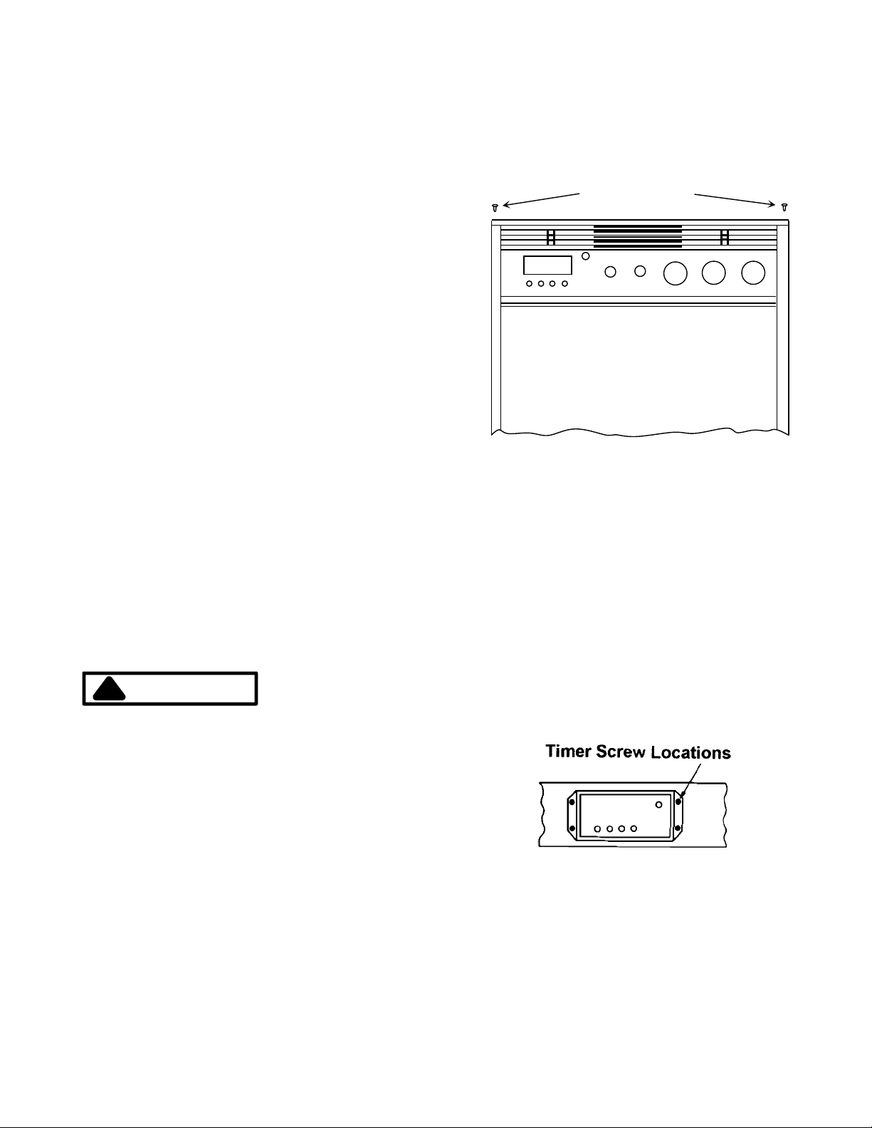
Oven Screw Locations
Screw Location
Final Gas Connection
The electrical supply should be turned off at the main
circuit breaker before attempting to make the final gas
connection.
The gas supply line assembled earlier must be connected to the pressure regulator on the oven. To gain
access to the pressure regulator, the control panel and
timer must be removed.
1. Remove knobs from the timer and control panel by
pulling them straight out.
2. Remove two screws securing control panel in place
as indicated in the illustration below.
Place Oven in Opening
Slide the oven on its cardboard shipping base to the
cabinet opening.
1. One person should lean the oven to the side.
2. A second person must remove the four screws from
the shipping base. Discard the screws and the shipping base.
3. Remove the oven doors by pulling them up and off
the oven.
4. One person should be positioned on each side of
the unit. Grasping the unit inside the lower oven and
on the bottom, lift it into the cabinet opening.
5. Plug in the power cord and push the oven back into
3. Remove four screws holding the timer in place.
4. Pull the timer forward and place it on the top oven
rack. There should not be any stress placed on the
harness connections.
5. Connect the supply line to the regulator using a
1/2-inch nipple, union and elbow. The supply line
should be accessed by reaching through the opening in the control panel area and through the upper
cabinet doors or removable panel. Use two
9 RA233001 Rev . 3

Installation Instructions
wrenches when tightening the connection. The
pressure regulator is die cast and will crack if too
much pressure is applied. Seal the connection with
an approved pipe joint compound.
WARNING
!
To avoid the risk of fire, personal injury or property
damage, do not overtighten the supply line to the
regulator. Overtightening the supply line can cause
the regulator to crack and leak gas.
Testing for Leaks
1. Turn on house gas supply.
2. Open the oven manual shut-off valve in gas supply
line.
3. Cover each gas connection with soap suds.
Bubbles indicate a leak.
4. If a leak is present, turn off the gas supply.
5. Tighten the joint or unscrew it completely and apply
additional pipe joint compound and retighten the
connection.
6. Retest each connection and repeat the above procedure until bubbles cease forming at the connections.
Outer Mantle - Dark Blue
Inner Cone - Blue-Green
Flame – Sectional View
1. Disconnect the electrical and gas supplies.
2. Remove the upper or lower oven door.
3. Remove screw under the plastic door latch knob.
Lift off the plastic knob (applies to upper oven only).
4. Remove three screws securing trim below oven
doors. Remove trim.
All factory fittings have been tested and tightened. Retest the factory fittings. If a leak is present, tighten the
fitting but do not add additional pipe joint compound.
Replace the timer and control panel by reversing steps
one through three under
nine.
WARNING
!
To avoid the risk of a fire, personal injury or property
damage, do not test for gas leaks with an open
flame. Do not apply pipe joint compound on factory
fittings.
Final Gas Connection
on page
Adjusting the Bake Burner Flame Size
The upper and lower ovens each have a bake burner.
The bake burner flame should have a glue-green inner
core and a dark blue outer mantle. The flame should be
clean and soft without yellow tips, blowing or lifting. The
flame should be 1/2-inch long (see following illustration). If the flame does not appear normal, adjust the air
shutter according to the following the directions.
Trim Removal
5. Loosen air shutter lock screw on bake burner. Close
the air shutter to decrease the amount of air to the
flame or open to increase the air amount. Retighten
lock screw.
Air Shutter
Lock Screw
RA233001 Rev . 3 10
Bake Burner

Installation Instructions
6. Reconnect electrical and gas supplies. Test flame
size and shape. If flame needs further adjustment,
repeat steps one through five.
7. When the flame is properly adjusted, verify air channel is in place, reassemble the trim and plastic door
knob latch.
Important Note: The air channel must be in place before operating the oven.
WARNING
!
To avoid the risk of electrical shock and personal
injury, do not attempt to insert anything in the
openings of the protective shield around the ignitor
coil. Do not attempt to clean this area.
Broil Burner Flames
There are two broiler burners, one in the top of each
oven. The broil burners will have a hazy or fuzzy appearance when in operation. This haze may be a maximum
of 3/8-inch thick and is normal for this type of burner.
examples.
Example One
1. Remove pressure regulator cap with a 7/8-inch
wrench.
2. Remove plastic insert from cap. Insert fits tightly in
cap.
3. Reverse plastic insert. Push firmly into hole in the
cap.
4. Verify insert fits tightly in hole. Do not disturb spring
in regulator body.
5. Replace cap in regulator body.
Important Note: The broil burner flames are not adjustable because the burners are equipped with a fixed orifice. The burners do not have air shutters.
Broil Burner Flame
Pressure Regulator Conversion
Several varieties of gas pressure regulators may equip
Amana and Modern Maid gas cooking products. All gas
pressure regulators perform the same function. In most
instances, universal pressure regulators are used in gas
cooking products. A universal regulator can be modified
to use either natural gas or liquefied petroleum (LP) gas
supplies.
Cooking products with universal pressure regulators are
set for a natural gas supply at the factory. Gas cooking
products can be connected to a natural gas supply without modifying the pressure regulator.
Example Two
1. Remove cap with screwdriver.
2. Remove insert.
3 Reverse insert and replace. “LPG10” is visible. Do
not disturb spring in regulator body.
4. Replace cap.
A universal pressure regulator, however, must be modified when connecting a gas cooking product to an LP
gas supply. How each type of universal pressure regulator is converted to LP use is illustrated in the following
Example Three
11 RA233001 Rev. 3

Installation Instructions
1. Remove cap marked “Nat.”
2. Reverse cap. “LP” now appears on cap.
3. Reinsert cap. Do not disturb spring beneath the
cap. Verify fiber washer is correctly placed between
cap the regulator body.
Important Note: Some models may not have
washers. If washer is not supplied, none is needed.
Example Four
1. Remove cap with screwdriver slot.
2. Reverse and replace cap. Verify “LPG10” is visible.
Do not disturb spring beneath cap.
Example Five
1. Remove cap with screwdriver slot.
2. Remove black insert marked “NAT” from cap. (Insert
fits tightly in cap.)
3. Reverse insert.
4. Replace in hole. Verify “LP” is visible. Verify that
insert is pressed firmly into shoulder. Do not disturb
spring in regulator body.
5. Replace cap in regulator body and tighten.
1. Remove cap with screwdriver slot.
2. Remove spring and washer. Washer will be at bottom of spring as illustrated below.
3. Reverse to bring washer to the top.
4. Reinstall spring and washer.
5. Tighten cap.
Converting Bake Burners
The bake burner is behind the horizontal trim on the
front of the unit below each oven door.
1. Remove oven doors by lifting them up and off the
unit.
2. Remove screw under the plastic door latch knob.
Lift off the plastic knob (applies to upper oven only).
3. Remove three screws securing the trim below the
oven doors. Remove the trim.
4. Locate the oven burner orifice hood. The orifice hood
is brass and protrudes into the oven burner air shutter.
5. Turn the orifice hood down onto the pin, approximately 1-1/2 to 2 turns. Do not overtighten the hood.
Overtightening may distort the hole.
6. Adjust the air shutters to a 11/16-inch opening.
7. Reassemble trim and latch knob. Check burners for
proper flame appearance.
Example Six
RA233001 Rev . 3 12
Important Note: The air channel must be in place before operating the oven.
Converting Insta-Broil Burners
The broil burner spuds must be changed from a natural
gas spud to an LP spud. Both upper and lower oven
broilers must be converted.
1. Remove screw securing broiler burner to the oven
cavity at the front of the burner.
2. Remove the burner by gently pulling to left and
down. Be careful not to damage ignitor. Spud will be

Installation Instructions
visible in the rear wall of oven.
3. Locate and remove the #59 LP gas spud wired to
the inlet pipe.
Gas Supply Connection
4. Use a 5/16-inch nut driver and remove the #52 natural gas spud from each oven. Save for future conversions. Wire the #52 natural gas spuds to the inlet
pipe.
5. Install the #59 LP spud in the orifice opening.
6. Reinstall the broiler burner using the screws removed in step 1.
The broil burner flames are not adjustable because the
burner is equipped with a fixed orifice. The burner does
not have an air shutter.
Bake burners are rated at 14,000 BTU for LP gas and
15,500 for natural gas. Broil burners are rated at 12,000
BTU for LP gas and 12,000 BTU for natural gas.
Oven Removal and Replacement
1. Turn off electrical and gas supplies.
2. Remove control panel and timer.
3. Disconnect gas connection.
4. Pull the oven forward out of the opening.
5. Unplug power cord.
6. Replace the oven using directions outlined earlier in
this section.
13 RA233001 Rev. 3
 Loading...