

Amana NEC3120FW0 Owner’s Manual
120-Volt Electric
120-Volt Electric
Compact Dryer
Use and Care Guide
Para una versión de estas instrucciones en español, visite www.amana.com
Table of Contents
DRYER SAFETY ......................................................................... 2
INSTALLATION INSTRUCTIONS ............................................... 4
USING YOUR DRYER .............................................................. 10
DRYER CARE ........................................................................... 12
TROUBLESHOOTING .............................................................. 13
WARRANTY .............................................................................. 15
ASSISTANCE OR SERVICE ..................................BACK COVER
Compact Dryer
par le dessus guide
d’utilisation et
d’entretien
Table des matières
SÉCURITÉ DE LA SÉCHEUSE ................................................ 16
INSTRUCTIONS D’INSTALLATION ......................................... 18
UTILISATION DE LA SÉCHEUSE ............................................ 24
ENTRETIEN DE LA SÉCHEUSE .............................................. 26
DÉPANNAGE ............................................................................ 27
GARANTIE ................................................................................ 30
ASSISTANCE OU SERVICE ............... COUVERTURE ARRIÈRE
W10773366A
W10773375A-SP
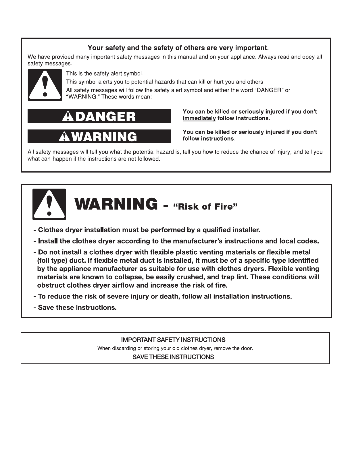
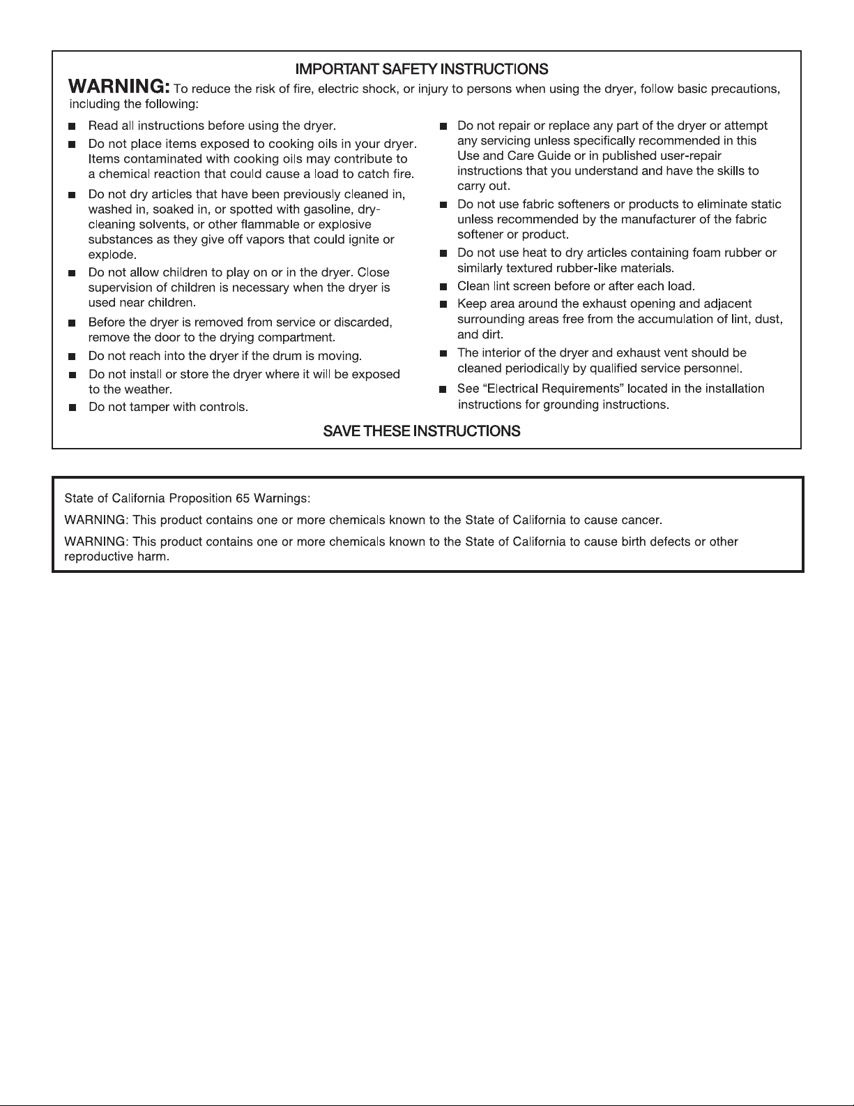
Dryer Safety
2
3
Installation Instructions
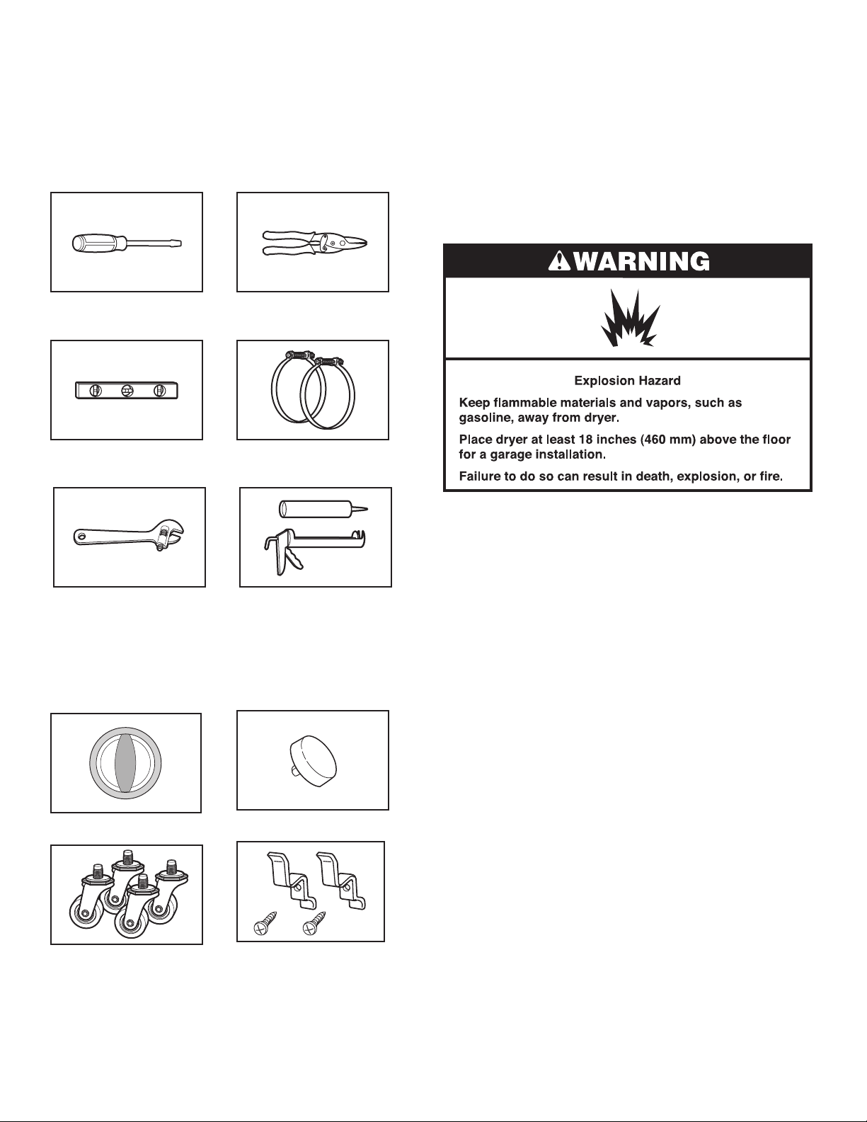
Tools and Parts
Tools needed
Gather the required tools and parts before starting installation.
Read and follow the instructions provided with any tools
listed here.
Flat-blade screwdriver Tin snips (new vent
installations)
Level Vent clamps
Parts needed
Check local codes, existing electrical supply and venting, and
see “Venting Requirements” and “Electrical Requirements” before
purchasing parts.
■ Mobile home installations require metal exhaust system
hardware.
For information on ordering, please refer to “Assistance or
Service” on the back cover. You may also contact the dealer
from whom you purchased your dryer.
Location Requirements
Adjustable wrench that opens
to 1" (25 mm) or hex-head
socket wrench
Caulking gun and compound
(for installing new exhaust vent)
Parts supplied
Remove parts package from the dryer drum. Check that all parts
listed are included.
Cycle control knob Start button
You will need
■ A location that allows for proper exhaust installation. See
“Venting Requirements.”
■ A 120-volt, 60-Hz., AC only, 15- or 20-amp circuit.
■ A grounded electrical outlet located within 2 ft (610 mm) of
either side of the dryer. See “Electrical Requirements.”
■ A sturdy floor to support the dryer weight (dryer and load)
of 115 lbs (52 kg). The combined weight of a companion
appliance should also be considered.
■ A level floor with a maximum slope of 1" (25 mm) under
entire dryer.
Do not operate your dryer at temperatures below 45ºF (7ºC). At
lower temperatures, the dryer might not shut off at the end of an
automatic cycle. Drying times can be extended.
The dryer must not be installed or stored in an area where it will
be exposed to water and/or weather.
Check code requirements. Some codes limit, or do not permit,
installation of the dryer in garages, closets, mobile homes, or
sleeping quarters. Contact your local building inspector.
Casters (4) Cord brackets (2) and
screws (2)
4
Installation Clearances
AB
(25 mm)
(305 mm)
(305 mm)
A B
C
(76 mm)
(76 mm)
The location must be large enough to allow the dryer door to
open fully.
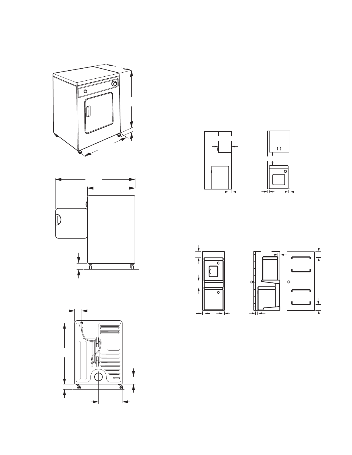
Dryer Dimensions
Front View
3
*20
/4"
(527 mm)
31"
(787 mm)
3
/4"
3
/4"
1
(44 mm)
(606 mm)
Side View
36"
(914 mm)
237/8"
20
(527 mm)
Minimum spacing for recessed area and
closet installation
The following dimensions shown are for the minimum spacing
allowed when the dryer is to be operated with, or without, the
Stack Stand Kit. To purchase a Stack Stand Kit, see “Assistance
or Service.”
■ Additional spacing should be considered for ease of
installation and servicing.
■ Additional clearances might be required for wall, door, and
floor moldings.
■ For closet installation with a door, minimum ventilation
openings in the top and bottom of the door are required.
Louvered doors with equivalent ventilation openings
are acceptable.
■ Companion appliance spacing should also be considered.
Recessed or closet installation - Dryer only
14"*
(356 mm)
18"* (457 mm)
51/2"*
(140 mm)
1"
(25 mm)
1"
13/4"
(44 mm)
Back View
1
3
/2"
(89 mm)
1
/4"
29
(743 mm)
13/4"
(44 mm)
(303 mm)
”
11
A. Side view - closet or confined area
B. Recessed area
*Most installations require a minimum 5½" (140 mm) clearance
behind the dryer for the exhaust vent with elbows. See “Venting
Requirements.”
Recessed or closet installation - Stacked
12"*
12"*
(25 mm)
51/2"
(76 mm)
48 in. *
(309.7 cm )
DRYER
24 in. *
WASHER
1"
1"
(25 mm)
1"*
(25 mm)
(154.8 cm )
A. Recessed area
B. Side view - closet or confined area
C. Closet door with vents
2
3"*
2
2
2
3"*
Mobile Home - Additional Location Requirements
31/4"
(83 mm)
This dryer is suitable for mobile home installations. The
installation must conform to the Manufactured Home
Construction and Safety Standard, Title 24 CFR, Part 3280
(formerly the Federal Standard for Mobile Home Construction and
Safety, Title 245, HUD Part 280) or Standard CAN/CSA-Z240 MH.
Mobile home installations require:
7
/8"
■ Metal exhaust system hardware, which is available for
purchase from your dealer.
■ Special provisions must be made in mobile homes to
introduce outside air into the dryer. The opening (such as a
nearby window) should be at least twice as large as the dryer
exhaust opening.
5
 Loading...