

Amana LGA90AW-PLGA90AW, LGA60AW-PLGA60AW, LGA60AL-PLGA60AL, LGA30AW-PLGA30AW, LGA50AL-PLGA50AL Installation Guide
...Page 1
Installation Instructions
Home Laundry Automatic l)ryers
(Electric and Gas. Models)
D3111E3A
KEEP THESE INSTt_UCTIONS FOR FUTURE REFERENCE. (If the dryer changes ownership, be
sure this manual accompanies the dryer.)
_1 WARNING
FOR YOUR SAFETY, the information in this manual must be followed to minimize the trisk of
fire or explosion or to prevent property damage, personal injury or death.
• Do not store or use gasoline or other flammable vapors and liquids in the vicinity of this or any
other appliance.
• WHAT TO DO IF YOU SMELL GAS:
- Do not try to light any appliance.
- Do not touch any electrical switch; do not use any phone in your building.
- Clear the room, building or area of all occupants.
- Immediately call your gas supplier from a neighbor's phone. Follow the gas supplier's
instructions.
- If you cannot reach your gas supplier, call the fire department.
• Installation and service must be performed by a qualified installer, service agency or the gas
supplier.
W033
W052
Part No. 503953
May 1997
Page 2
Table Of
Contents
Rei_lacement Parts ;,!2L_.,,L:.Z.2._I,I..I..,:_'........LI .............. ................ :.. 2
Roughing In Dimensions ..................................................................... 3
Before You Start
Tools ................................................................................................ 4
Exhaust ............................................................................................. 4
Electrical ........................................................................................... 4
Gas ..................................................................................................... 4
Location ............................................................................................. 4
Installing the Dryer
STEP 1 (Position and Level the Dryer) ........................................... 5
STEP 2 (Connect Dryer Exhaust System) ........... :............................. 5
STEP 3 (Connect Gas Supply Pipe) .................................................. 6
STEP 4 (Connect Electrical Plug) ,.................................................... 7
STEP 5 (Wipe Out Inside of Dryer) .................................................. 8
STEP 6 (Plug in the Dryer) ............................................................... 8
STEP 7 (Check Installation) .............................................................. 8
Heat Source Check ................................................................................ 9
Electric Dryers .................................................................................. 9
Gas Dryers ........................................................................................ 9
Reversing Door Procedure ................................................................. 10
Manufactured (Mobile) Home Installation ....................................... 11
Electrical Requirements (Electric Dryers) ....................................... 12
Electrical Plug Connection .................................................. ............... 13
Electrical Requirements (Gas Dryers) .............................................. 14
Gas Requirements .............................................................................. 15
Location Requirements ...................................................................... 16
Dryer Exhaust Requirements ........................................................... 17
Exhaust System Materials ............................................................... 17
Make UP Air Requirements ............................................................. 17
Exhaust System ............................................................................... 18
Exhaust Direction ............................................................................ 18
Exhaust System Maintenance .......................................................... 19
Dryer Airflow ................................................................................. 19
Reduced Clearance Elbow ............................................................... 19
User-Maintenance Instructions ......................................................... 20
Lubrication ............ ......................................................................... 20
Care of Your Dryer ......................................................................... 20
Exhaust System ............................................................................... 20
Information for Handy Reference .......................... Inside Back Cover
Installer Check .................................................................... Back Cover
Replacement Parts...
If replacement parts are required,
contact the source where you
purchased your dryer, or contact
© Copyright 1997, Raytheon Appliances
Alll rights reserved. No part of the contents of this book may be reproduced or transmitted in any form or by any means without
the written permission of the publisher.
2 503953
Raytheon Appliances
Amana Home Appliance Division
2800 220th Trail
P.O. Box 8901
Amana, IA 52204-0001
Phone:
(800) 843-0304 in U.S.A.
(319) 622-5511 Outside U.S.A.
FAX: (319) 622-2977
for the name and address of the
nearest authorized Amana parts
distributor.
Page 3
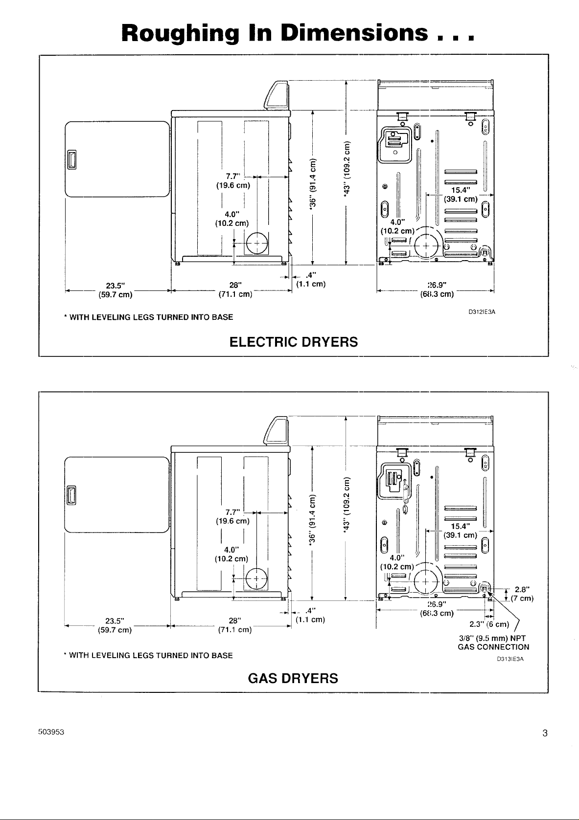
Roughing In Dimensions...
1--
E
o
v
23.5"
(59.7 cm)
* WITH LEVELING LEGS TURNED INTO BASE
(71.1 cm)
i
28"
ELECTRIC DRYERS
E
o
o_
26.9"
(6&3 cm) ---"
D3121E3A
!
E
o
o3
o
v
_ III 15.4"
4.0" _LW '===='
(10.2cm)/ L"\_
u_,=_ /,,'_',-_'_
.-__,,,,4(7 o_)
23.5"
(59.7 cm)
* WITH LEVELING LEGS TURNED INTO BASE
28"
(71.1 cm)
GAS DRYERS
503953 3
(68.3 cm) _2
2.3"(6c_) /
3/8" (9.5 mm) NPT
GAS CONNECTION
D3131E3A
Page 4
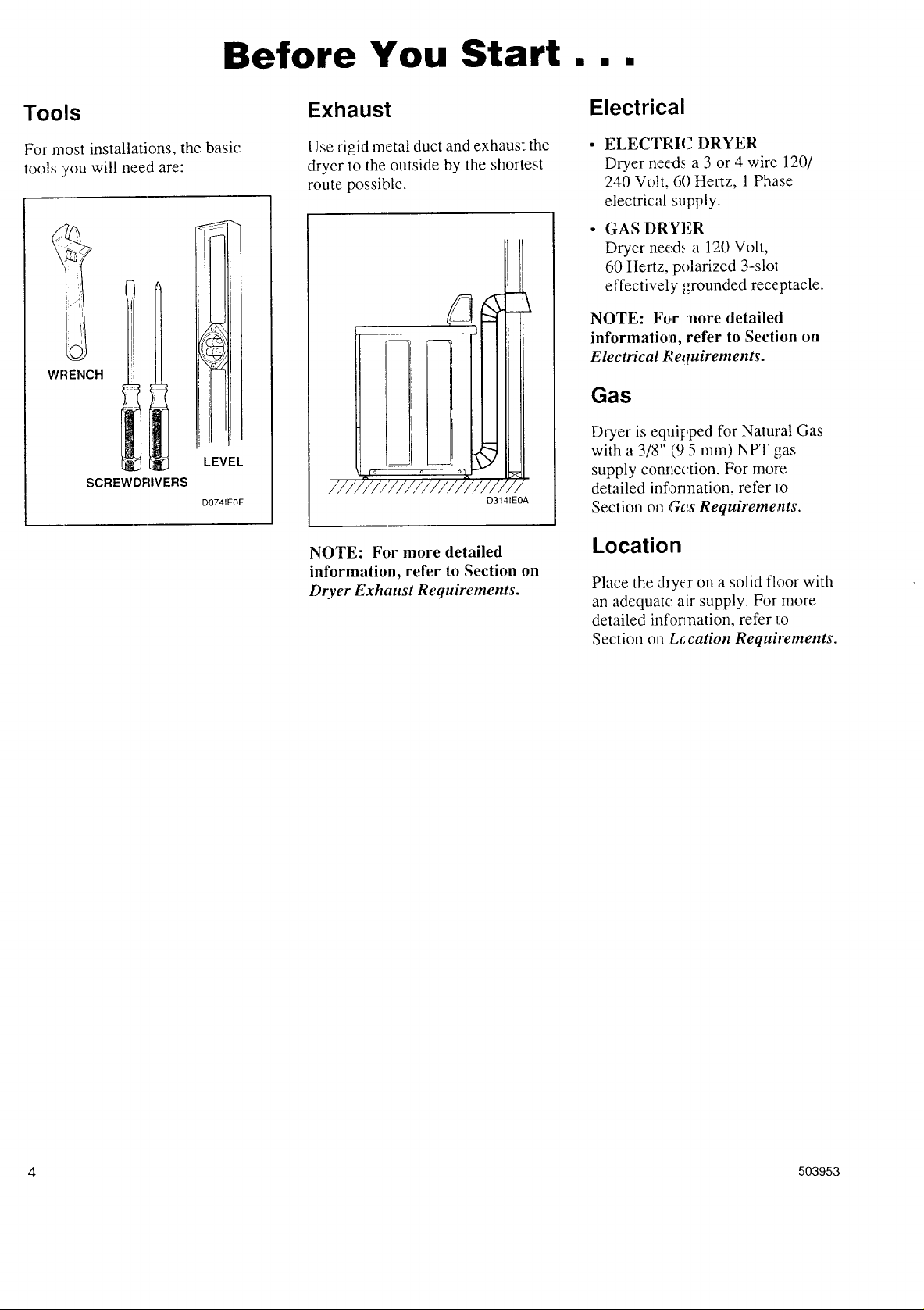
Before You Start...
Tools
For most installations, the basic
tools you will need are:
WRENCH
1'
i ii
LEVEL
SCREWDRIVERS
D0741EOF
Exhaust
Use rigid metal duct and exhaust the
dryer to the outside by the shortest
route possible.
o o o]
_///////////,r/ ////
///
NOTE: For more detailed
information, refer to Section on
Dryer Exhaust Requirements.
D3141EOA
Electrical
• • • (-1ELEC I RI _ DRYER
Dryer needs a 3 or 4 wire 120/
240 Volt, 60 Hertz, 1 Phase
electrical supply.
• GAS DRYER
Dryer need: a 120 Volt,
60 Hertz, polarized 3-slot
effectively _grounded receptacle.
NOTE: For :more detailed
information, refer to Section on
Electrical Requirements.
Gas
Dryer is equipped for Natural Gas
with a 3/8" (9 5 mm) NPT gas
supply connection. For more
detailed infarmation, refer lo
Section oll Gvs Requirements.
Location
Place the dryer on a solid floor with
an adequate air supply. For more
detailed information, refer I:o
Section on Lc.cation Requirements.
4 503953
Page 5
STEP 1 : ..........
Po., iti( ,n /
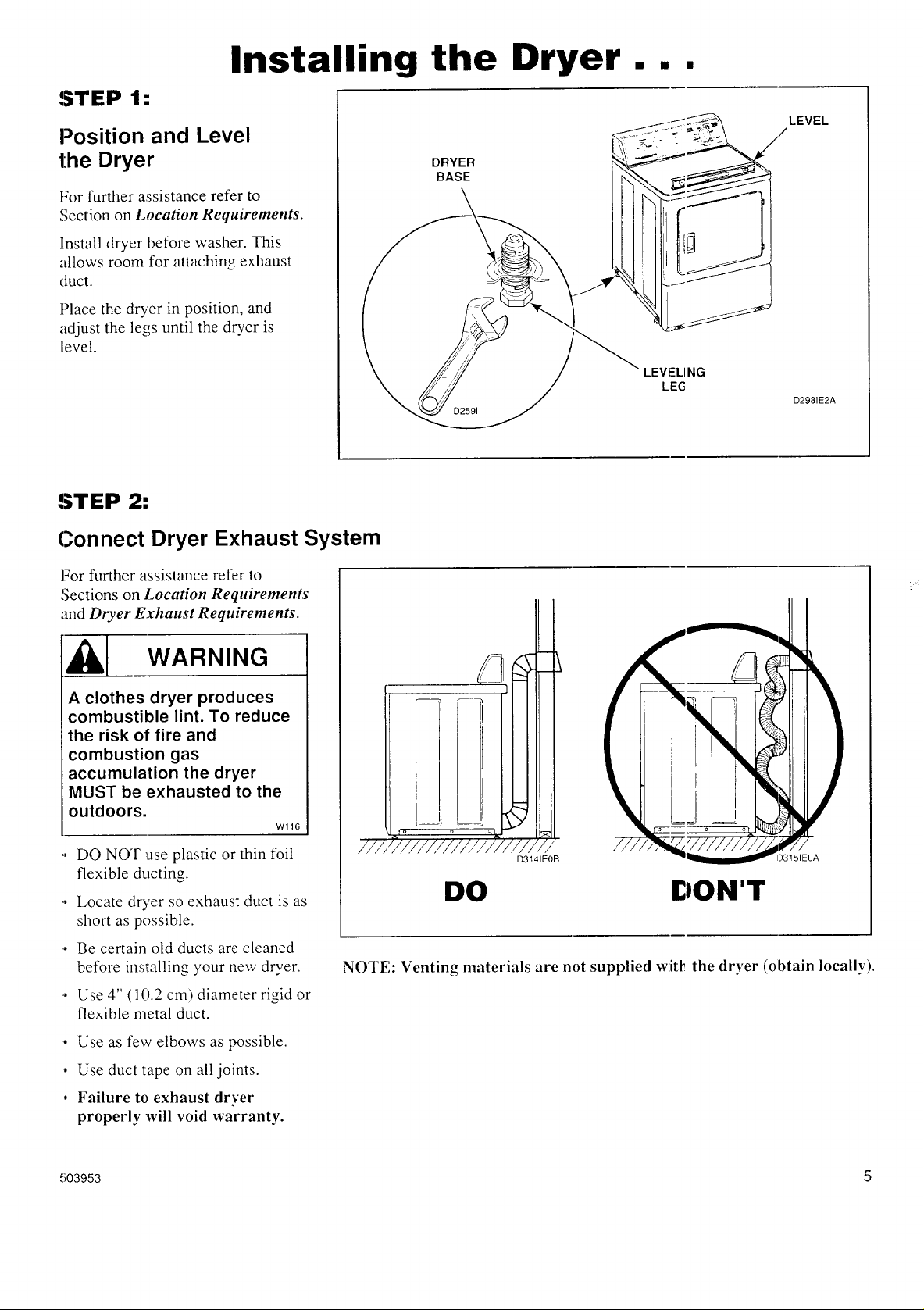
Position and Level
,nsta,,,n,Or,er
the Dryer
BASE
For f
For further assistance refer to
Section on Location Requirements.
Insta
Install dryer before washer. This
allo,_
allows room for attaching exhaust
duct.
Place the dryer in position, and [
adjust the legs until the dryer is
level.
LEVELING
LEG
STEP 2:
Connect Dryer Exhaust System
For further assistance refer to
,_ecttons on Location Requirements
and Dryer Exhaust Requirements.
D2981E2A
-----_ WARNING
A clothes dryer produces
combustible lint. To reduce
the risk of fire and
combustion gas
accumulation the dryer
MUST be exhausted to the
outdoors.
Wl16
,. DO NOT use plastic or thin foil
flexible ducting.
,. Locate dryer so exhaust duct is as
short as possible.
,. Be certain old ducts are cleaned
before installing your new dryer.
,. Use 4" (l 0.2 cm) diameter rigid or
flexible metal duct.
• Use as few elbows as possible.
• Use duct tape on all joints.
. Failure to exhaust dryer
properly will void warranty.
D314]EOB
)3151EOA
DO DON'T
NOTE: Venting materials are not supplied w:itl!:the dryer (obtain locally).
503953 5
Page 6
STEP 3: (Gas Dryer ONLY)
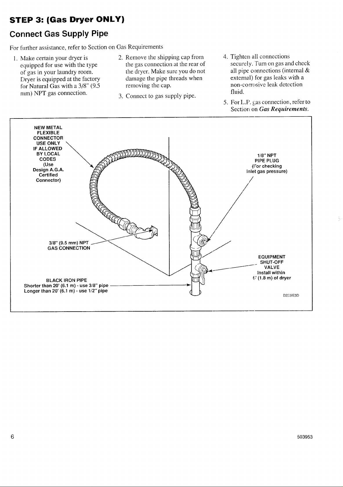
Connect Gas Supply Pipe
For further assistance, refer to Section on Gas Requirements
1. Make certain your dryer is
equipped fc)r use with the type
of gas in your laundry room.
Dryer is equipped at the factory
for Natural Gas with a 3/8" (9.5
mm) NPT gas connection.
NEW METAL
FLEXIBLE
CONNECTOR
USE ONLY
IF ALLOWED
BY LOCAL
CODES
(Use
Design A.G.A.
Certified
Connector)
2. Remove the shipping cap from
the gas connection at the rear of
the dryer. Make sure you do not
damage the pipe threads when
removing the cap.
3. Connect to gas supply pipe.
4. Tighten all connections;
securely. Turn on gas and check
all pipe connections (internal &
external) for gas leaks with a
non-cocrosive leak detection
fluid.
5. For L.P. gas connection,, refer to
Section on Gas Requirements.
1/8" NPT
PIPE PLUG
(For checking
inlet gas pressure)
/
3/8" (9.5 mm) NPT
GAS CONNECTION
BLACK IRON PIPE
Shorter than 20' (6.1 rn) - use 3/8" pipe
Longer than 20' (6.1 m) - use 1/2" pipe
jr
.__....._/- VALVE
EQUIPMENT
SHUT-OFF
Install within
(i' (1.8 rn) of dryer
D2331E3D
6 503953
Page 7
STEP 4: (ELECTRIC DRYER ONLY)
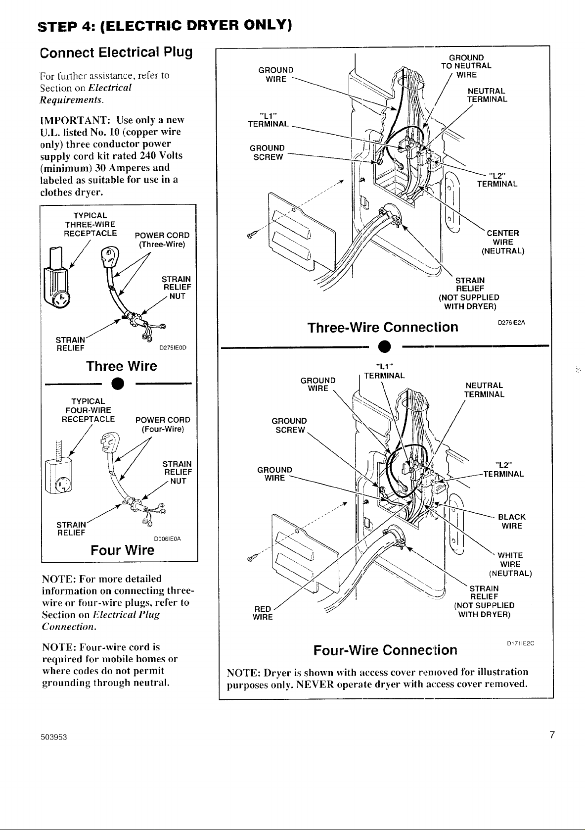
Connect Electrical Plug
For further assistance, refer to
Section on Plectrical
.Requirements.
IMPORTANT: Use only a new
U.L. listed No. 10 (copper wire
only) three conductor power
supply cord kit rated 240 Volts
(minimum) 30 Amperes and
labeled as suitable for use in a
clothes dryer.
TYPICAL
THREE..WIRE
RECEPTACLE POWER CORD
(Three-Wire)
RELIEF
NUT
S_FRAIN
STRAIN/f-m_ ===_
RELIEF D2751EOD
GROUND
WIRE
"L1"
TERMINAL
GROUND
SCREW
Three-Wire Connection
e
GROUND
TO NEUTRAL
NEUTRAL
WIRE
TERMINAL
TERMINAL
CENTER
(NFUTRAL)
STRAIN
RELIEF
(NOT SUPPLIED
WITH DRYER)
"L2"
WIRE
D2761E2A
Three Wire
e
TYPICAL
FOUR-WIRE
RECEPTACLE POWER CORD
(Four-Wire)
__ STRAIN
RELIEF
Four Wire
NOTE: For more detailed
information on connecting three-
wire or four-wire plugs, refer to
Section on Electrical Plug
Connection.
NOTE: Four-wire cord is
required for mobile homes or
where codes do not permit
grounding through neutral.
D0061EOA
"L1"
GROUND
WIRE
TERMINAL
NEUTRAL
TERMINAL
\
GROUND
SCREW.
GROUND
WIRE
RED
WIRE
(NOT SUPPLIED
WITH DRYER)
Four-Wire Conneclion
NOTE: Dryer is shown with access cover removed for illustration
purposes only. NEVER operate dryer wilh access cover removed.
"L2"
BLACK
WIRE
WHITE
WIRE
(NEUTRAL)
AIN
RELIEF
D!711E2C
IAL
503953 7
Page 8
STEP 5:
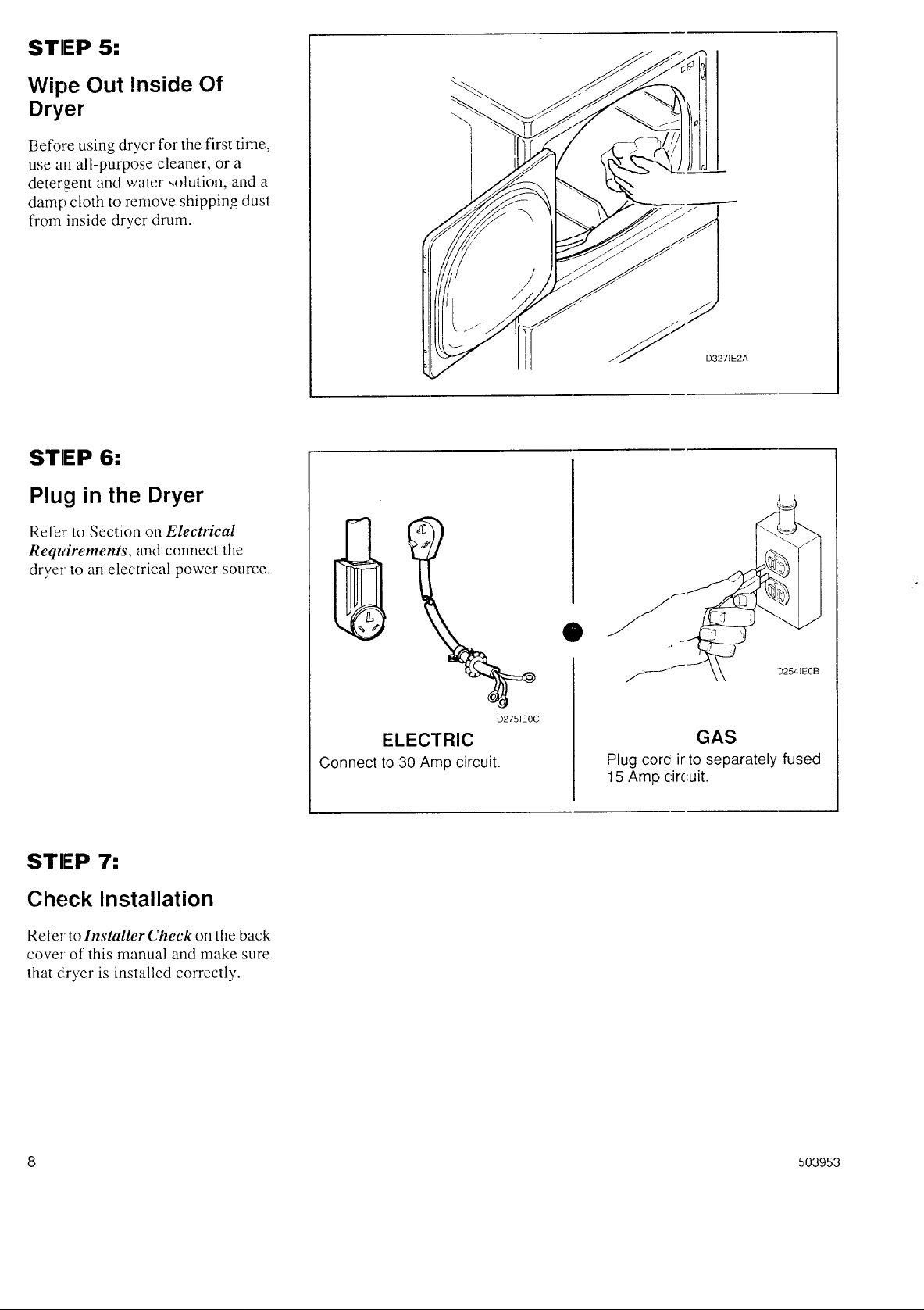
Wipe Out Inside Of
Dryer
Befo_:e using dryer for the first time,
use an all-purpose cleaner, or a
detergent and water solution, and a
damp cloth to remove shipping dust
from inside dryer drum.
STEP 6;
Plug in the Dryer
D3271E2A
Ret'e_: to Section on Electrical
Requirements, and connect the
dryer to an electrical power source.
STEP 7:
Check Installation
Refer to Installer Check on the back
cover of this manual and make sure
that dryer is installed correctly.
ELECTRIC
Connect to 30 Amp circuit.
O
32541EOB
D2751EOC
GAS
Plug corc into separately fused
15 Amp circuit.
8 503953
Page 9

Heat Source Check...
Electric Dryers
Close the loading door and start the
dryer in a heat setting (refer to the
Use and Care Guide supplied with
the dryer). After the dryer has
To view the burner flame, remove
the lower front panel of the dryer.
Close the loading door, start the
dryer in a heat setting (refer to the
Use and Care Guide supplied with
the dryer); the dryer will start, the
igniter will glow red and the main
burner will ignite
][MPORTANT: If all air is not
purged out of gas line, gas igniter
may go off before gas is ignited. If
this happens, after approximately
two minules igniter will again
attempt gas ignition.
operated for three minutes, the
exhaust air or exhaust pipe shouhl
be warm.
Gas Dryers
After the dryer has operated for
approximately five minutes,
observe burner flame through lower
front panel. Adjust the air shutter to
obtain a soft, uniform blue flame. (A
lazy, yellow tipped flame indicates
lack of air. A harsh, roaring, very
blue flame indicates too much air.)
Adjust the air shutter as follows:
a. Loosen the air shutter
lockscrew.
b. Turn the air shutter to the left to
get a luminous yellow-tipped
flame, then turn it back slowly
to the right to obtain a steady,
soft blue flame.
c. ASter the air shutter is adjusted
for proper flame, tighten the air
shut :er lockscrew securely.
d. Reir stall the lower front panel.
WARNING
For personal safety, lower
front panel must be in place
during normal operation.
W046
After ::he dryer has operated for
approximately three minutes,
exhaust air or exhaust pipe should
be wa::m.
1/8" (3.1 mm) PIPE PLUG
(For checking
manifold pressure)
AIR SHUTTER
LOCKSCREW
/
APPLIANCE
MAIN GAS
VALVE
AIR
SHUTTER
D3161E3A
503953 9
Page 10

Reversing Door Procedure...
The, door on this dryer is completely reversible. To reverse door
proceed as follows:
D271PEOA
Remove four hinge attaching
screws.
®
I D272PEOA
I
&
Remove all nine screws.
®
®
P /
I
I
oIIJ.JiI]
Pull bottom of door liner out,
then pull down, removing door
liner from do3r panel.
®
/-js- [_
i,i ........
kL --"
Rotate door panel 180 degrees
as shown.
D273PEOA
$
D270PEOA
Reinstall nine screws removed
in S:ep 2.
D276PEOB
Remove door strike from door
liner and reinstall on opposite
side.
®
Using a screwdriver, remove
two door plugs, and reinstall on
opposite side of door opening.
< . 269PE0
Insert liner under flange on top
of door, then push bottom of
door liner nt3 place.
®
D275PEOA
Reinstall foL r hinge attaching
screws re-noved in Step 1.
10 503953
Page 11

Manufactured (Mobile) Home
Installation...
IMPORTANT: Installation must conform to "_
the Manufactured Home Construction and |
Safety Standards, Title 24 CFR, Part 32-80 or l
andard CAN/CSA-Z240 MH__p...J
The dryer can be installed in a
manufactured (mobile) home by
following these instructions:
1. IMPORTANT: Gas dryers
MUST be permanently
attached to the floor at the
time of installation. Order No.
526P3 Dryer Installation Kit
for a manufactured (mobile)
home installation. Follow the
instructions supplied with the
kit.
2. Electrical Connections (Electric
Dryer Only) must be a 4-wire
connection, refer to page 13.
3. Venting--Dryer MUST be
exhausted to the outdoors.
WARNING
To reduce the risk of fire and
combustion gas
accumulation, the dryer
MUST BE EXHAUSTED TO
THE OUTDOORS. Refer to
Section on Dryer Exhaust
Requirements.
W047
The dryer can be exhausted to the
outdoors through the back, left,
right or bottom panel. Gas dryers
cannot be exhausted out the left
side because of the burner
housing.
The dryer exhaust duct must be:
secured to the mobile home
structure.
Exhaust ducts MUST NOT be
connected with sheet metal
screws or fasteners which extend
into the duct.
Exhaust duct must not be
connected to any other duct, vent
or chimney.
Dryer exhaust duct MUST NO-['
terminate under the mobile home.
For proper operation, it is
important that tile dryer has an
ample amount of outside make-
up air. The free area of any
opening for the introduction ot
outside air must be at least 25 in2
( 163 cm2).
• When exhausting the, dryer to the
outdoors, the dryer can be
installed with "0" inch clearance
a! the sides and rear. Clearance of
the du =t from combustible
constraction must be a minimum
of 2 irlches (5.08 cm).
• Venting materials are not
supplied with the dryer (obtain
locally).
WARNING
To reduce the risk of fire, the
exhaust duct and weather
hood MUST be fabricated of
a material that will not
support combustion. Rigid
or flex ible metal pipe is
reconl mended for a clothes
dryer.
W048
503953 11
Page 12

Electrical Requirements...
NOTE: The wiring diagram is
located inside the control hood.
WARNING
To reduce the risk of fire,
electric shock, serious
injury or death, all wiring
and grounding MUST
conform with the latest
edition of the National
Electrical Code, ANSI/NFPA
70, or the Canadian
Electrical Code, CSA C22.1,
and such local regulations
as might apply. It is the
customer's responsibility to
have the wiring and fuses
checked by a qualified
electrician to make sure
your home has adequate
electrical power to operate
the dryer.
Grounding Instructions
This dryer must be connected to a
grounded metal, permanent wiring
system; or an equipment-grounding
conductor must be run with the
circuit conductors and connected to
the equipinent-grounding terminal
or lead on the dryer.
W113
(Electric Dryers)
POWER SUPPLY
_ CIRCUIT BREAKER
I [ ] NEUTRAL WtRE NEUTRAL WIRE
FUSE BOX
INTERMEDIATE _='_'_ /
(MAY BE METALLIC OR
OMITTED IF I _ I TM NON-MErALLIC
SERVICE I I_ _ • SHEATHED CABLE
ENTRANCE I I I I (COPPERWIRE
BOX IS WALLFUSED)_ _ ONLY)
RECEPTACLE _ PIGTAIL
L1 L2
PIGTAIL CONNECTION
/ 30-Amp
/ Three-wire
I i q_ A typical
240 _+12
VAC
NOTE: Use COPPER WIRE only.
Shorter than 15' (4.5 m) use 10 A.W.G.
Longer than 15' (4.5 m) use 8 A.W.G.
3-WIRE GROUNDED NEUTRAL
E ENTRANCE SWITCH BOX
120/240 VOLT, 60 HERTZ AC 1 PHASE
SEE NOTE BELOW) --'--_"
0 AMPERE ]:USES OR -----}
TO DRYER
S (SEE NOTE BELDW)
Receptacle
OOWER SUPPLY
INTERMEDIATE
SHUT-OFF BOX
(MAY OR MAY
NOT BE FUSED}
"RAL
L I L2
DIRECT CONNECTION
DOC31E2E
NOTE: The power cord (pigtail) is
NOT supplied with the electric dryer.
Type of pigtail ancl gauge of wire
must conform to local codes and
instructions.
The method of wiring the dryer is
optional and subject to local code
requirements,
NOTE: Connect the dryer to the power
:supply with the MAXIMUM RATED
'VOLTAGE listed on the nameplate.
12 503953
Page 13

Electrical Plug Connection...
-Three-Wire Plug Four-Wire Plug
I
D2841EOA
1. Remove access cover from
rear o1!dryer.
l. Remove access cover from rear
of dryer.
!
D2841EOA
GROUND
SCREW
4. Attach power cord ground
(greta:) wire to rear bulkhead
using ground screw removed in
Step 2.
"LI"
TERMINAL
WHITE
NEUTFIAL
TERMINAL
TERMINAL
BLACK
Use the three screws from the
.
envelope located in the cylinder
to attach the remaining power
cord wires to the terminal block
as tol tows:
"L2"
D2891EOC
D2851EOB
2. Use a strain relief and insert
end of power cord through
power supply hole.
"LI" /Ill 11 _ NEUTRAL
TERM ._._INAL
)y_ TERL2NAL
_f_ D2861EOA
. Use the three screws flom the
envelope located in the
cylinder to attach the power
cord wires to the terminal
block.
4. Tighten all screws and
reinstall access cover
removed in Step 1.
D2871EOC
2. Remove ground screw and save
for use in Step 4. Remove wire
and use in Step 5.
POWER
CORD
WIRE
D288;EOB
3. Use a strain relief and insert end
of power cord through power
supply hole.
a. Red wire to "LI" terminal.
b. BIack wire to "[,2" terminal.
c. White wire to Neutral
te[minal.
NOTE: When installing the white
wire, loop the free eyelet end of
the ground wire (removed in Step
2) and atlach along with the white
wire to the neutral (center)
terminal on the terminal block.
6. Tighten all screws ;and reinstall
access cover remo,,ed in Step 1.
503953 13
Page 14

Electrical
D..,, ; +
(Gas Dryers)
NOTE: The wiring diagram is
located inside the control hood.
WARNING
To reduce the risk of fire,
electric shock, serious
injury or death, all wiring
and grounding MUST
conform with the latest
edition of the National
Electrical Code, ANSl/NFPA
70, or the Canadian
Electrical Code, CSA C22.1,
and such local regulations
as might apply. It is the
customer's responsibility to
have the wiring and fuses
checked by a qualified
electrician to make sure
your home has adequate
electrical power to operate
the dryer.
• DO NOT
OVERLOAD
CIRCUITS
• DO NOT
USE AN
ADAPTER
• DO NOT
USE AN
EXTENSION
CCRD
DO091EOC
Wl!3
Grounding Instructions
The dryer must be grounded. In the
event of malfunction or breakdown,
grounding will reduce the risk of
electric shock by providing a path of
least resistance for electric cmTent.
The dryer is equipped with a cord
having an equipment-grounding
conductor and a 3-prong grounding
plug. The three-prong grounding
plug on the power cord should be
plugged directly into a polarized
three-slot effectively grounded
receptacle rated 110/120 Volts AC
(alternating current) 15 Amps.
WARNING
Improper connection of the
equipment-grounding
conductor can result in a
risk of electric shock. Check
with a qualified electrician
or service person if you are
in doubt as to whether the
dryer is properly grounded.
W038
Do not modify the plug provided
with the dryer--if it will not fit the
outlet, have a proper outlet installed
by a qualified electrician.
WARNING
STANDARD 120 VOLT,
60 HFRTZ, 3-WIRE
EFFECTIVELY GROUNDED CIRCUIT
L1 NEUTRAL
115 + 1;
V.A.C.
NEUTRAL_ -I
SIDE
ROUND
GROUNDING
PRONG
D0901EOD
NOTE: Have a qualified
electrician check the polarity of
the wall receptacle. If a voltage
reading is measured other than
that illustral ed, the qualified
electrician should correct the
problem.
Do not operale other appliances on
the same ci:cuit when this appliance
is operating.
WARNING
This dryer is equipped with
a three-prong (grounding)
plug for your protection
against shock hazard and
should be plugged directly
into a properly grounded
three-prong receptacle. Do
To reduce the risk of an
electric sh ock or fire, DO
NOT use an extension cord
or an adapter to connect the
dryer to the electrical power
source.
W037
not cut or remove the
grounding prong from this
plug.
W035
14 503953
Page 15

Gas Requirements...,
NOTE: The gas service to a gas
dryer must conform with the local
codes and ordinances, or in the
absence of local codes and
ordinances, with the latest edition
of the National Fuel Gas Code
ANSI Z223.1/NFPA 54 or the
CAN/CGA-B149, National Gas
_[nstallation Code.
Natural Gas service must be
supplied at 6.5 + 1.5 inch water
column pressure.
17orproper operatio n at altitudes
above 2,500 feet (760 m) the natural
gas valve spud orifice size must be
reduced to ensure complete
combustion. See table at right.
L.P. Gas service must be supplied at
10 + 1.5 inch water column
pressure.
NOTE: DO NOT connect the
dryer to L.P. Gas Service without
converting the gas valve. An
LPK1 Sales Accessory (L.P. Gas
Conversion Kit 649P3) must be
installed.)
(Gas Dryers)
WARNING
To reduce the risk of gas leaks, fire or explosion:
• The dryer must be connected to the type of gas as shown on
nameplate located in the door recess.
• Use a new flexible metal connector.
• Use pipe joint compound insoluble in LP Gas on all pipe
threads.
• Purge air and sediment from gas supply line before
connecting it to the dryer. Before tightening the connection,
purge remaining air from gas line to dryer until odor of gas is
detected. This step is required to prevent gas valve
contamination.
• Do not use an open flame to check for gas leaks. Use a non-
corrosive leak detection fluid.
Wl14
Altitude Orifice Size Part
m # Inches mm Number
3000 915 43 0.0890 2.26 503778
6000 !830 44 0.0860 2.18 58719
8000 2440 45 0.0820 2.08 503779
9000 2740 46 0.0810 2.06 503780
10000 3050 47 0.0785 1.99 503781
NOTE: The dryer and its
appliance main gas valve must be
disconnected from the gas supply
piping system during any
pressure testing of that system at
lest pressures in excess of 1/2 psi
(3.45 kPa). (See illustration on
page 10.)
The dryer must be isolated from the
gas supply piping system by closing
the equipment shut-off valve during
any pressure testing of the gas
supply piping system at test
pressures equal to or less than
[/2 psi (3.45 kPa)
NOTE: When connecting to a gas
line, an equipment shutoff valve
must be installed within 6' (1.8 m)
of the dryer. An 1/8" (3.1 ram)
N.P.T. pipe plug must be installed
as shown. See illustration.
NEW METAL \
FLEXIBLE
coN.EChO.\
USE ONLY _,,_ _.
IF ALLOWED _" _
BY LOCAL
CODES ,_
(Use
Design A.G.A. l_
Certified
Connector)
3/8" (9.5 ram) NPT / _
GAS CONNECTION
BLACK IRON PIPE
Shorter than 20' (6.1 m) - use 3/8" pipe ____-
Longer than 20' (6.1 m) - use 1_2" pipe
1/8" (3.1 mm) NPT
PIPE PLUG
._ (For checking
inlet gas; pressure)
QUIPMENT
1"-11 SHUT-OFF
.j] _ _ VALVE
_ _._2_)_ -_ Installed within
,_ 6' (1.8 m) of dryer
503953 15
Page 16

Location Requirements...
Select a location with a solid floor.
No other fuel burning appliance
should be installed in the same
closet with the dryer.
The dryer must not be installed or
stored in an area where it will be
exposed to water and/or weather.
:../
) /i
/i
Leveling legs can be adjusted from
inside the dryer with a 1/4" driver.
All four legs must rest firmly on the
floor so the weight of the dryer is
evenly distributed. The dryer must
not rock.
CLOSET
DOOR
/
__l__J __
-'--Am i
/
i,
The dryer neeJs sufficient clearance
and an adequate air supply for
proper operation and ventilation,
and for easLer installation and
servicing. (M inimum clearances are
shown below )
/ " -: i}
/"
1
CENTERED
AIR
OPENINGS (G)
(_ (20p,mings
Minimum)
**42"
l
•!'
l
i
]
" F
"*'C
SIDE VIEW OUTER
(w/o Closet Door)
AREA DESCRIPTION FREE STANDING / ALCOVE CLOSET INST._LLATION
INSTALLATION :(See Illustration)
(See Illustration)
A Dryer sides and rear clearance 0" (0 cm) 0" (0 cm)
B Dryer top clearance t2" (30.5 cm) 12" (30.5 cm)
C Dryer front clearance Not Applicable 2" (5.1 cm)
D Exhaust duct clearance to 2" (5.1 cm) 2" (5.1 cm)
combustible material
E Weather hood to ground clearance 12" (30.5 cm) 12" (30.5 cm)
F Distance from t]ooror ceiling to Not Applicable 3" (7.6 cm)
hole edge
G* Area of centered air openings m Nol Applicable 40 sq. in./open (260 sq. cm)
closet door
WALL OF
ENCLOSURE
FRONT VIEW
(Closet Door)
D317IE3A
*Louvered door with equivalent air openings is acceptable. (Minimum clearances are sh(,wn.)
** NOTE: For new installations, locate top of wall vent 42 inches above floor to make wmting easier to
connect.
16 503953
Page 17

Dryer Exhaust Requirements...
WARNING
A clothes dryer produces
combustible lint. To reduce
the risk of fire and
combustion gas
accumulation the dryer
MUST be exhausted to the
outdoors..
I
W1!6
This gas appliance contains
or produces a chemical or
chemicals which can cause
death or serious illness and
which are known to the
State of California to cause
cancer, birth defects, or
other reproductive harm. To
reduce the risk from
substances in the fuel or
from fuel combustion, make
sure this appliance is
installed, operated, and
maintained according to the
instructions in this manual.
W115
To reduce the risk of fire and
the accumulation of
combustion gases, DO NOT
exhaust dryer air into a
window well, gas vent,
chimney or enclosed,
unventilated area, such as
an attic, wall, ceiling, crawl
space under a building or
concealed space of a
building.
W045
To reduce the risk of fire, DO
NOT use plastic pipe or
flexible plastic pipe to
exhaust the dryer.
W041
i
_'////////////_/////
///
DO
Exhaust System
Materials
Exhaust duct must be four inches
(10.2 cm) in diameter having no
obstructions. Rigid metal duct is
recommended. Non-combustible
semi-rigid flexible metal duct is
acceptable. Do not use plastic pipe
or flexible plastic pipe, because il
contributes to poor drying
performance and collects lint, which
can lead to a fire hazard.
DO NOT use sheet metal screws on
exhaust pipe joints or other fasten mg
means which extend into the duc!
that could catch lint and reduce the
efficiency of the exhaust system.
Secure all joints with duct tape.
D3141EOB
:,3151EOA
DON'T
Make-Up Air
Requirements
For proper operation it is important
that you .ocate the drycr in an area
that hat an ample amount of make-up
air to replace the amount exhausted
by the dryer.
Energy efficient homes with low air
infiltration rates should be equipped
with an air exchanger that can
accommodate on demand inake-up
air needs in the home. These devices
can be obtained throug;h your
building contractor or building
material suppliers.
Never install flexible duct in
concealed spaces, such as a wall or
ceiling.
503953 17
Page 18

Exhaust System
Exhaust Direction
IMPORTANT: Keep exhaust
duct as short as possible.
NOTE: Be certain old ducts are
cleaned before installing your
new dryer.
For best drying results,
recommended maximum length of
exhaast system is shown below.
To prevent backdraft when dryer is
not in operation, outer end of
exhaust pipe must have a weather
hood with hinged dampers (obtain
locally).
NOTE: Weather hood should he
installed at least 12 inches (30.5
cm) above the ground.
Number of
90 ° Elbows Recommended
The dryer can be exhausted to the
outdoors through the back, left, right
or bottom of the dryer.
EXCEPTION: Gas dryers cannot
be vented out the left side because
of the burner housing.
Dryer is shipped from factory ready
for rear exhaust; no kits required.
Exhausting the dryer through sides
or bottom can be accomplished by
installing a DK1 Sales Accessory
(Directional Exhaust Kit 528P3)
available as optional equipment at
extra cost.
Weather Hood Type
Use only for short run
D3281EOA
528P;I Directional
Exhaust Kit
installations
(10.16 cm)
4"
(10.16 cm) o011E2o
2-1/2"
(6.35 cm)
DO1 [IE2E
Maximum length of 4" (10.2 cm) diameter rigid metal duct.
0
1
2
3
44 feet (13.4 m)
34 feet (10.4 m)
26 feet (7.9 m)
20 feet (6.1 m)
Maximum length of 4" (10.2
0 24 feet (7.3 m)
1 20 feet (6.1 m)
2 16 feet (4.9 m)
3 12 feet (3.7 m)
cm) diameter flexible metal duct.
34 feet (10.4 ra)
26 feet (7.9 rn)
120feet (6.1 rn)
14 feet (4.3 m)
20 feet (6. I m)
16 feet (4.9 m)
12 feet (3.7 m)
8 feet (2.4 no)
NOTE: Deduct 6 feet (1.8 m) for each additional elbow.
18 503953
Page 19

Exhaust System
Maintenance
The dryer interior and the complete
exhaust system should be inspected
after one year of use and cleaned if
necessary. Inspect and clean exhaust
duct every one to two years as
required thereafter. The weather
hood should be checked frequently
to make sure the dampers move
freely, dampers are not pushed in
and that nothing has been set against
them. This maintenance work
should be done by a qualified
service person.
WARNING
To reduce the risk of electric
shock, disconnect the
electrical service to the
dryer before cleaning.
W043
Dryer Airflow
Efficient dryer operation requires
proper dryer airflow. Proper dryer
airflow can be evaluated by
measuring the static pressure.
Static pressure in the dryer's
exhaust duct should be no greater
than that shown in the chart below.
(Check with dryer running and no
load.)
NOTE: This can be measured
with a manometer placed on the
exhaust duct approximately two
feet (61 cm) from the dryer, see
illustration below.
MAXIMUM STATIC
PRESSURE IN
WATER COLUMN
.6 INCHES (1.5 cm)
MANOMETER
Reduced Clearance
Elbow
Installirtg the dryer in shallow
closets ,:an be accomplished by
using an Elbow, Part No. 62688,
which i_;one inch narrower than a
standard venting elbow.
D3191
Reduced Clearance
Elbow
Exhausting the dryer in hard-to-
reach locations can be accomplished
by installing the 521P3 Flexible
Metal Vent Kit, available as
optional equipment at extra cost.
The kit comes in two halves that can
be separately attached to the dryer
and wall outlet. Once attached, the
dryer can be slid back into position
and the two halves can be connected
from the front.
EXHAUST
DUCT
Measuring Static Pressure
DO121EOA
521 P3 Metal
503953 19
Page 20

User.Maintenance Instructions...
• Lubrication
All moving parts are sealed in a
permanent supply of lubricant or
are equipped with oilless
bed.rings, Additional lubrication
will not be necessary.
• Care of Your Dryer
Clean the lint filter after drying
each load. The lint filter may be
washed if needed. Occasionally
reraove lint filter and vacuum the
area under it.
Ordinarily, the dryer cylinder will
need no care_
Wipe the dryer cabinet as needed.
If detergent, bleach or other
washing products have been
spilled on the dryer, wipe
immediately. Some products will
cause permanent damage if
spilled on the cabinet.
Do not allow sharp or rough
objects to lean against the dryer.
The finish could be damaged.
Use only a damp or sudsy cloth
for cleaning the control panel.
Some spray prewash products
may harm the finish on the control
panel.
NOTE: The wiring diagram is
located inside the control panel.
CAUTION
Label all wires prior to
disconnection when
servicing controls. Wiring
errors can cause improper
and dangerous operation.
W049
• Exhaust System
The exhaust duct should be
inspected after one year of use and
cleaned if necessary. Inspect and
clean exhaust duct every one to
two years _Lsrequired thereafter.
The weather hood should be
checked frequently to make sure
the dampers move freely, dampers
are not pushed in and that nothing
has been set against thern.
Keep drTer area clear and free
from coml:,ustible mater!Ms,
gasoline and other flammable
vapors and liquids.
Do no! ob.,:,truct the flow of
combustion and ventilation air.
NOTE: Verify proper operation
after servicing.
20 503953
Page 21

503953 21
Page 22

22 503953
Page 23

Information for Handy Reference...
Raytheon Appliances
Amana Home Appliance Division
2800 220th Trail
P.O. Box 8901
Amana, IA 52204-0001
Date Purchased
Model Numbe.r
Dealer's Name
Dealer's Address
Service Agency
Service Agency Address
NOTE: Record the above information and keep your sales slip. Model and serial numbers are located on
the nameplate.
Serial Number
Phone Numbe:
Phone Numbe:
503953 23
Page 24

Fast Track for Installing the Dryer
(Refer to the manual for more detailed information)
O. Position and Level
The Dryer.
(]]) LEVEL (_
Installer Check...
--ELECTRIC ONLY
O• Connecl Electrical Cord.
J
CHECK
• Connect Dryer Exhaust System.
!iii
CHECK CHECK
-- GAS ONLY
_). ConnectGas
Supply Pipe.
• Check for Gas
Leaks.
-N
J
O. Plug In The Dryer.
EL[__CTRL,
• Wipe Out
I aside Of Dryer.
GAS
"N
J
J
_ CHECK
CHECK
503953
 Loading...