

Page 1
BUILT-IN DISHWASHER
INSTALLATION INSTRUCTIONS
PLEASE READ COMPLETE INSTRUCTIONS BEFORE YOU BEGIN
PRINTED IN USA © 1999 - Maytag Corporation
6 915126
Page 2
TO OK M IC ISSA IY TOR IN STA UAT ION ^
riNG KNIFE
O
RATCHET
O
3/16", 1/4", 5/16" SOCKETS
O
PHILLIPS SCREWDRIVER
O
STANDARD SCREWDRIVER
O
WIRE CUTTERS
O
CRESCENT WRENCH
O
ADJUSTABLE PLIERS
O
LEVEL
^ (Not indiided: Tools required for preparing
the cabinet opening).
UN CRAT ING
® Remove access and toe panels before beginning installation.
0 Remove bolts from the crate base brackets, using 5/16" socket with ratchet. Remove crate base and
discard base and packaging. Until dishwasher is permanently installed, beware of opening the
door as the unit may tip forward.
@ Open the door and remove accessory package from silverware basket
O Remove any extra packing material from outside and inside the dishwasher. This would include plug in water valve inlet
© Loosen front leg bolts with a crescent wrench. Adjust rear leg bolts in same manner.
--------------
; (ifJ’uVPre iraeastteyiaihilei. hfiafti';joAhA!::iv|)llie'insl}5;.a:ih.e:, JiisiiAA5bev:sh<iidife.v:'ban::ihal :ot ipq:i'a1i:vi!r.i lojiAmsp:
SUPPORT ACCESSORIES:
O 3/4" UL Approved Strain Relief (provided)
O 2 Appropriate Sized Wire Nuts
O 3/8" Male (N.P.T.) Compression Elbow
or Flare Elbow
O Thread Sealing Tape or Pipe Thread Compound
O Appropriate Sized Hose Clamp
O 2 Wood Mounting Screws (provided)
Water Hook-Up Kits Available:
{Water line, wafer valve fitting, TpfiofW'' tapp, tee valve jlt.iinn)
5’ Braided Stainless Steel Part #19950153
5' Copper Part #19950152
Available through an autlioitzed Maytag Parts Retailer
NOTE; Make sure you have everything
necessary for proper installation before
going to step 2.
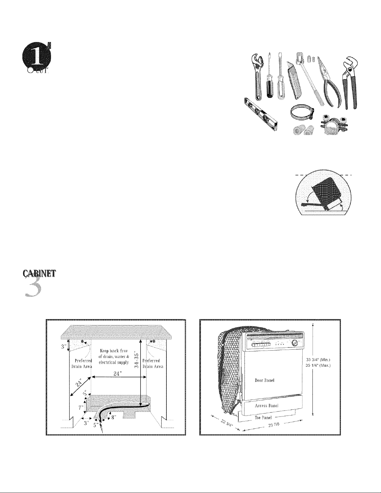
PRIPAIATION
Prepare cabinet as needed. Electrical and water facilities should enter cabinet opening on the floor, or through the back or side walls,
as shown in the shaded poi'tion of the drawing. Preferred drain outlet is shown in the upper portion of the cabinet in drawing below.
Care should be taken to route plumbing away from the motor and blower {if equipped). DO NOT make connections until dishwasher
is in position. Care should be taken to make sure cabinet holes for power cord and hoses have no sharp edges.
cabinet opening dishwasher dimensions
CUSTOM PANELS AVAILABLE Dishwashers come with pre-installed panels. Custom panels are available; stainless steel and
trims kits for wood panels. See your authorized selling dealer for a complete list of products
available.
Page 3

WATM¥ALVEP1IPARATI01 ■ ■
® Remove shipping plug from water inlet valve.
© Install a 90° elbow (3/8” N.P.T) fitting into the water valve using Teflon™ tape
or pipe thread compoiiiid. The opposite end of the fitting should fit in-coming hot
water supply line. Position the end of the elbow towards the rear of the dishwasher,
IMPORTANT: DO NOT connect a sweat type fitting directly to the water valve
as the required heat will damage the water inlet valve. Do not solder within 6”
(15.2 cm) from the water valve.
/3:ii]t ■Pciiiij.
- that the drain hose be routed high enough to provide the 32” loop. If a loop cannot be put in the installation, an air gap (not included)
Diagram A
—-
/A
aiht pcnjhOitvvJlie ;iisjfVV.asll.c.r A isar-k t.b.h.№..l;Ul;;i
ntti he V'.'-.'ilkr va.fve fii lifig.-.°.V : : '.V : r °
;i!!a! iOii
CAUTION; With the door open, dishwasher may tip forward if
it is not secure in position to cabinet.
'i
ivisuifiiiof'lwaie
liit.i qi;-a.l;i.rv.
ikCC. i:'st1
Ci> i;.i cpKiijf
hA
f
is;
ifRAIl iOSI PMPAEATION
Distiwasher drain must have a 32" (81.2) loop. Drain hose may be dipped to either side of the dishwasher (see diagram A). It is preferred
may be used.
IMPORTANT: Routing of the drain hose is most important to insure satisfactory operation. It is not reconiniended
to extend drain line beyond T (2.1 in). However, should this be necessary, it must always be attached to a line
of larger inside diameter. An accessory drain hose extension kit (#904204) is available through your authorized
dealer. DO NOT route drain hose across the top of the tub, all bends must be gradual to prevent kinking or
collapsing of the hose.
IMPORTANT: Drain hose may change position even after installation. To insure proper operation, secure hose
to either side of cabinet wall, or to tub with hose dip (provided) to assure a 32" loop. Make certain there are
no kinks.
IMPORTANT: Do not attach the drain hose to any connection smaller than 1/2” I.D.
(Side view of dishwasher)
IMPORTANT: Never cut the corrugated portion of drain hose. All connections
must be made to rubber portions of drain hose. If cutting of drain hose is required,
do not cut past the 5/8" line.
DIAIN
A 5/8” (1.6 cm) I.D. (Inside Diameter) x 7 ft (2.1 m) corrugated drain hose is positioned
on side of dishwasher tub.
Drain hose connection can be located on either side of compartment Elevate drain hose
to a height of at least 32" (81 cm) above the floor. If drain connection is to be made
below the floor, hose should be left in the looped position. It may be necessary to extend
drain hose for connection. DO NOT reduce the drain hose to less than 1/2" (1.3 cm) ID.
(Inside Diameter),
i'O Srr iO NING TH E DtSH mSH lR
■ O With the door latched, position dishwasher in front of cabinet opening. Insert
drain hose through the opening provided.
0 Guide dishwasher into the cabinet, pulling drain hose through opening as you
proceed. Make sure drain hose is not kinked.
.
Multi-flex Drain Hose
Page 4

posmoNwc; ras dishwashbr {«»»tinued)
Virtii'ii HS'ivijliii!;; dNilvtiifilli-!VKrK!‘ H n|r!:H^i Vijiirir
LE ¥EL WS IWA SII R
Leveling legs align the disliw asher vertically and horizontally, A combination of these
two adjustments are iietessan to properly position the dishwasher and insure proper fit
of door and latch, Dislr,\ashei must be LEVEL, solid, and square,
: :i !|jr;.1;by;vgHn:! !i!c yqnLr lidicHbiaiHiy ittUiiniifitiin tiiHyayy^ cisitti :!: sii.i:atib;i :iH(;et;-:. i
S1CU M16 TH E ilSl WAS ll -: H
Make pilot holes in the underside of counter and drive wood screws, provided in the
accessory package, through holes in the dishwasher mounting bracket. If part of
the bracket extends beyond the cabinet front, they may be trimmed with wire
cutters, provided sufficient material is left to support dishwasher mounting.
lliior to
Note: Dishwasher must be secured properly to
countertop to avoid tipping when the door is open and
to prevent the tub from twisting.
It may be necessary to provide an additional
anchoring source for mounting screws. Wood
strips across the top of dishwasher opening can be
used for solid surface or granite type counters to secure the dishwasher.
iTiii;-:Rt:.!Vi; i.C':Viuintyi-l.t.qrCii;a‘UjrrU;.t;;crcc fc|c: t'Orlijik::/:':
ciwajisiftjv sw;n)tiig;ai>hw.bsi):cr ; ■ ■
iMI i lOS i A TTA CHMI NI '
^ If draining into tlie disposer, check to make sure disposal plug has been removed.
If not, remove as shown.
© With dishwasher in permanent position, clamp drain hose to a properly sized
drain line.
Page 5

MAKING Til mCTMCAL CONIICTIOIS------------
SEE THE ELECTRICAL REQUIREMENTS SECTION
CAUTION: Verify power to dishwasher is off at source.
^ Remove terminal box cover.
® In order to secure the power supply cable, a UL listed strain relief must be used to secure
the power supply to the back of terminal box.
© Strip approximately 3/8” (.09 cm) of insulation from incoming power supply wires. Connect
these wires to wires from dishwasher wire harness located in the terminal box. Connect
wires using the appropriate size wire nuts, twisting and tightening securely over the wire
connections. Connect white to white and black to black.
: :TiA/; ict'cficil
® Attach external ground wire from beliind washer of green grounding screw. If an external
groiiiidwire is used, insert the wire through the cable clamp and attach behind washer of
the green grounding screw. Attach the other end of external ground wire to a suitable
external ground. If a question arises, refer to your local
electrical codes.
iil'oi:.stsiUie.-sc.iiev'h liJlr
ies'.AftiitepCrii /1 eji/f.t
Secure the strain relief and replace the terminal box cover.
'MMm iooiop
ctibii'.' oil wii't reiii.'Jf:
Miaiii nelief
CHECK LOCAL PLUMBING CODES FOR APPROVED PLUMBING
-
----------
"PROCEDURES AND ACCESSORIES.ALL PLUMBING SHOULD BE DONE
IN ACCORDANCE WITH NATIONAL AND LOCAL CODES.
Connect water supply line to water valve. Minimum 3/8" O.D, copper tubing or equivalent
SHUTOFF VALVE; Install a hand shutoff valve in the water supply line in an accessible location, such as under the sink. The shutoff is optional,
but recommended and may be required by local codes. Connections are preferable located toward the left side of dishwasher. Care should be taken
to route plumbing away from motor and blower (if equipped). DO NOT make these connections until the dishwasher is in position.
Care should be taken to protect dishwasher and water lines leading to dishwasher from freezing. Damage from freezing is not covered by the
warranty.
- FINAUZING TII INSTAUATIOl
^ Turn water supply.on and check roniiectioiis for leaks.
0. Turn power supply'OIL ; .
# Re-install Acess and Toe.panels rem.Qved in step 2.
® Run ■dishvyasher.-thro.iigh Rins.e and Hold sir equivalent cycle.
@ Check .drain hose connection for leak,.. . . . .
Page 6

CAUTION: Disconnect electrical power before you start!
This dishwasher is designed for
ALL ELECTRICAL WIRING AND GROUNDING
SHOULD BE DONE IN ACCORDANCE WITH
operation on an adequately
wired individuai 120 VAC,
NATIONAL AND LOCAL CODES.
60 Hz approved electrical
circuit. Use required fuse {15
amp) or comparable circuit
breaker. Two wire with ground
service to the dishwasher
is recommended for connection
at the terminal box and for
ijijiìyTiì ;dtv
ipiicvv; :(ihf
ns :pN:fv.; ii
V ■ bo : -y-sert;
bwasjTiT/topdcijiTiti
: T.iiyt.fcivit: IT: AijfbfT'.'biiflf' id
ivi /
g-r’itooficjbdvtiTTr i;t:j :
■ PntoiA-ud;-wi 1 ti/ ÌTùb-f qiaiV
TO; TÌltó'-eìjTKiSm
Tu
:Ì:T:
. :.
grounding.
GROUNDING INSTRUCTIONS
w Af UdU-ÌV;:-liyrqyirTì'i itìT
1 ' Lid k-Mig : ■ ÌB cO: / TUiVTUU TÌ'iifiUif:
f-'k-ciTtoi
/H/lf;!; fiu
This appliance must be connected to a grounded metal, permanent wiring system; or an equipment-grounding conductor
must be run with the circuit conductors and connected to the equipment-grounding terminal or lead on the appliance.
biybqqkv ic
■■■iÙ-Ty .i:' :
Hbidi Li» rm
■UìViyjih-jyi
/■AfftìyTt:
oUttAitfetiV'y;
ifcphintai
imììrerrts-i
Dhlu\.r.*i SiiU’.iPW
CAUTION: Disconnect electrical power to dishwasher before you start!
CHECK LOCAL PLUMBING CODES FOR APPROVED PLUMBING
PROCEDURES AND ACCESSORIES. ALL PLUMBING SHOULD BE DONE IN
ACCORDANCE WITH NATIONAL AND LOCAL CODES.
BOOR SPRING ABJUSTMINT
The door lias two main springs, one located on each hinge. There are two slots on each hinge that allow
for door adjustment with the access panel removed.
To change door spring tension, use a 1/4" liex-niit driver to either loosen or tighten a single screw located
" *
To increase spring tension: (If door falls too fast) Tighten each screw by turning clockwise.
To decrease spring tension: (If door falls too slowly) Loosen each screw by turning counterclockwise.
For heavy wood panels, an auxiliary booster spring kit is available.
on each door spring adjustment bracket. The spring adjiistnient brackets are located on either side of the
dishwasher frame. These brackets stretch the springs by sliding forward and back along the dishwasher
frame.
 Loading...