

Page 1

Service
Bottom Mount Refrigerators
Base manual covers 84” tall
bottom mount refrigerators.
Service Manual for
Amana
Refer to “Technical Sheet”, part #12074201
for values and wiring schematics.
®
This manual is to be used by qualified appliance
technicians only. Amana does not assume any
responsibility for property damage or personal
injury for improper service procedures done by an
unqualified person.
Raytheon
Appliances
RS1200001
Revision 0
November 1996
Page 2
Safety and Electrical Information
Safety Symbols, Words, and Labels
DANGER
Immediate hazards which will result in
severe personal injury or death.
WARNING
Hazards or unsafe practices which could
result in severe personal injury or death.
Caution
Hazards or unsafe practices which could
result in minor personal injury or product or
property damage.
Amana Refrigeration, Inc. is not responsible for
personal injury or property damage resulting from
improper service. Review all service information
before beginning repairs.
Warranty service must be performed by an
authorized Amana® technician. Amana Refrigeration,
Inc. also recommends contacting an authorized
Amana® technician if service is required after
warranty expires. Contact (319) 622-5511 for further
assistance.
Grounding Information
Standard color for ground wires is green or green with
yellow striping. Ground wires are not to be used as
conductors carrying current. Compressor, condenser
fan motor, evaporator fan motor, defrost timer,
temperature control, and ice maker are grounded
through an individual wire attached to electrical
component and another part of refrigerator. Ground
wires should not be removed from individual
components while servicing unless component is
removed and replaced. It is extremely important to
replace all grounds prior to completing service. When
nib-headed screw is used to complete grounding
circuit, replace screw with a like screw.
Electrical Requirements
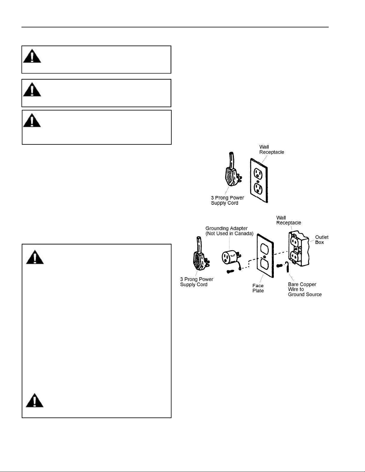
WARNING
Electrical Grounding Instructions -- This
refrigerator is equipped with a three-prong
(grounding) plug for protection against
possible shock hazards. If a two-prong wall
receptacle is encountered, contact a qualified
electrician and have the two-prong wall
receptacle replaced with a properly grounded
three-prong wall receptacle in accordance
with the National Electrical Code.
Refrigerator is designed to operate on a
separate 103 to 126 volt, 15 amp., 60 cycle
line.
Do not under any circumstances cut or
remove the round grounding prong from
the plug. Refrigerator must be grounded
at all times. Do not remove warning tag
from power cord.
WARNING
Do not use a 2 prong adapter.
Do not use an extension cord.
RS1200001 2 November 1996
Page 3

Contents
Safety and Electrical Information
Safety Symbols, Words, and Labels ....................... 2
Electrical Requirements .......................................... 2
Grounding Information ............................................. 2
Installation Instructions ............................................... 5
Sound Information ...................................................... 9
System Diagnosis
Pressure and Relationship Chart........................... 10
Refrigerant Overcharge Symptoms .......................11
Refrigerant Shortage Symptoms............................11
Restriction Symptoms ............................................11
Air in System Symptoms....................................... 12
Low or High Ambient Temperature Installation .........
Symptoms.............................................................. 12
Heat Load Symptoms............................................ 12
HFC134a Service Information
Health, Safety, and Handling................................. 13
Comparison of CFC12 and HFC134a Properties.. 13
Service Equipment ................................................ 14
Drier Replacement ................................................ 14
Replacement Service Compressor ....................... 15
Refrigerant Charge ................................................ 15
Leak Testing........................................................... 15
Evacuation and Charging ...................................... 15
Refrigerant Flow ....................................................... 17
Air Flow ..................................................................... 18
Machine Compartment Assembly ............................ 19
Component Function and Testing............................. 20
Electronic Functional Description ............................. 25
Electronic Testing Mode ........................................ 26
Forced Defrost Activation .................................. 26
Forced Compressor Activation ........................... 26
Open Thermistor Detect..................................... 26
Key Board Functions ............................................. 26
Display On Pad .................................................. 26
Warmer Pad ....................................................... 26
Colder Pad ......................................................... 26
Freezer Temp Pad.............................................. 27
Ref Temp Pad .................................................... 27
Vacation Pad ...................................................... 27
Max Ref Pad ...................................................... 27
Max Frz Pad....................................................... 27
Alarm Off Pad .................................................... 27
Display Off Pad .................................................. 27
Door Open Alarm ............................................... 27
High Temp .......................................................... 27
Temperature Control Operation............................. 27
Adaptive Defrost Operation................................... 28
Power Up Condition............................................... 28
EEPROM Update in Control Memory ................... 28
Accessing Program Mode .................................. 28
Operation............................................................ 29
Mode A Functions .............................................. 29
Mode B Functions .............................................. 29
Exiting Program Mode ....................................... 30
Refrigeration and Defrost Component Checks .........
Made at High Voltage Board ................................. 32
Circuitry ................................................................. 33
Freezer Compartment Refrigeration ......................
Cycle Circuitry .................................................... 33
Fresh Food Compartment Refrigeration ................
Cycle Circuitry .................................................... 33
Fresh Food and Freezer Compartment .................
Refrigeration Cycle Circuity ............................... 33
Adaptive Defrost Circuitry .................................. 33
Door Disassembly Procedures
Air Discharge Grille ............................................... 34
Refrigerator Door................................................... 34
Freezer Drawer and Basket................................... 34
Door Stops............................................................. 34
Door Handles......................................................... 34
Door Gaskets......................................................... 34
Inner Door Liners and Outer Door Shells .............. 34
Refrigerator Door Switch ....................................... 34
Cabinet Components Disassembly Procedures
Refrigerator Fan .................................................... 35
Refrigerator Light Switch ....................................... 35
Refrigerator Light Socket ....................................... 35
Center Mullion ....................................................... 35
Freezer Switches and Thermistor Panel ............... 35
Freezer Evaporator Cover ..................................... 35
Defrost Thermostat................................................ 35
Evaporator Defrost Heater .................................... 35
Evaporator ............................................................. 35
Evaporator Fan Blade ........................................... 35
Evaporator Fan Motor ........................................... 35
Front and Rear Roller Assembly ........................... 35
Water Valve ........................................................... 35
Condensate Drain Pan .......................................... 36
Shelf Support Ladders........................................... 36
Chef's Pantry Assembly ........................................ 36
Refrigerator Thermistor ......................................... 36
Machine Compartment Disassembly Procedures
Machine Compartment Access ............................. 37
Low and High Voltage Board and Showroom Switch
Access ................................................................... 37
Low Voltage Board................................................. 37
High Voltage Board ................................................ 37
Compressor, Condenser, and Condenser .................
Fan Access ............................................................ 37
Capacitor ............................................................... 37
Overload and Relay ............................................... 37
Condenser Fan Blade............................................ 37
Condenser Fan Motor............................................ 37
Precondenser Pan Loop ........................................ 37
Compressor ........................................................... 37
Condensate Drain Pan .......................................... 38
Condenser ............................................................. 38
Power Disconnect Switch ...................................... 38
Showroom Switch.................................................. 38
Typical External Sweat Pattern ................................ 39
Troubleshooting Guide .............................................. 40
November 1996 3 RS1200001
Page 4

Contents
Ice Maker
Operation ............................................................... 42
Specifications ........................................................ 42
Testing Procedures ................................................ 42
Disassembly Procedures ....................................... 43
Cover.................................................................. 43
Module, Motor, and Support Assembly .............. 43
Shut-off Arm ....................................................... 43
Module and Heater Assembly ............................ 43
Fill Cup ............................................................... 43
Ejector Blades or Stripper .................................. 44
Accessing Control Box ....................................... 44
Water Fill Adjustment............................................ 44
Water Problems..................................................... 45
Temperature Problems .......................................... 45
Thermostat ............................................................ 45
Wiring Harness ...................................................... 45
Water Valve ........................................................... 46
Wiring Harness ...................................................... 46
Ice Maker Troubleshooting Chart ............................. 47
Ice Maker Wiring Diagram and Parts Layout ........... 50
Trim Kit Installation Instructions
B136CKR1 and B136CKL1 Custom Handle Kit.... 51
B136SPK1 1/4” Facia Front Enclosure Kit............ 58
B136SPK2 3/4” Side Panel Kit.............................. 65
RS1200001 4 November 1996
Page 5
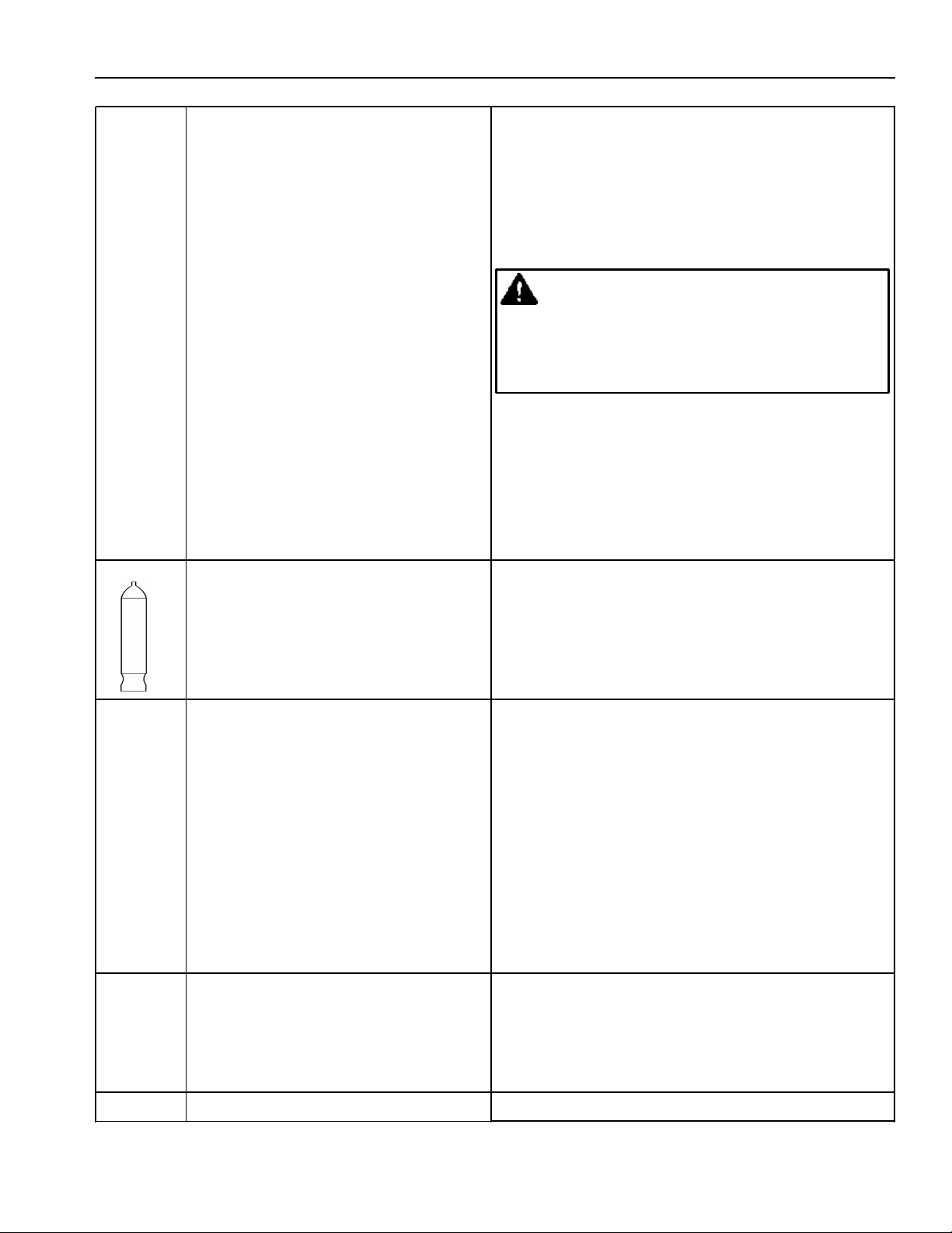
Installation Instructions
Uncrating
WARNING
To avoid severe personal injury or property
damage from refrigerator tipping over, 2 or
more people are required to install
refrigerator. Take caution when removing
refrigerator from skid. Do not drop refrigerator.
Do not open more than one door at a time,
until refrigerator has been secured to
structure. Refrigerator is top heavy and easily
tips.
Caution
To avoid personal injury, wear gloves
when performing any installation procedure.
The 2 x 4 mounting board, for securing refrigerator to
wall, is attached to top rear of refrigerator. Save
cardboard to protect walls when installing refrigerator.
1. Remove top and bottom strap.
2. Remove top cap.
3. Cut along dashes on carton rear with a utility knife
extended 1/4".
4. Remove carton, exterior packaging, and tape from
lag screws. Do not remove nylon cord from power
cord.
5. Remove shipping brackets from skid by removing 4
bolts with a 7/16" socket head screwdriver.
6. Strap refrigerator on cart. To prevent doors from
opening, tilt refrigerator to handle side. Remove
refrigerator from skid.
7. To avoid floor damage, use protective material.
Caution
To avoid property damage, protect soft vinyl
or other flooring with protective material when
moving refrigerator. Verify wheels are clean
before placing refrigerator on flooring.
Securing
WARNING
To avoid severe personal injury or property
damage from refrigerator tipping over, do not
open more than one door at a time, until
refrigerator has been secured to the structure.
Secure refrigerator to structure using lag bolts
located in the refrigerator's machine
compartment.
1. Locate and mark 2 wall studs to mount 2x4. See
"Installation Specifications". Do not cover electrical
outlet with 2x4.
Locate and predrill 1/4" holes in 2x4. Countersink
2x4 for bolt heads using a wood bit. See "Installation
Specifications".
2. Remove 2x4 mounting board from top rear of
refrigerator. Bolt 2x4 securely to wall studs with
supplied bolts. If application does not have studs
such as a framed wall mount to wall, not surface,
using a minimum 1/4" diameter fasteners (not
supplied). If cabinets are deeper than 24" mounting
board must be shimmed and structurally secured to
the 2 x 4 board. Longer bolts are required to shim
mounting board.
3. To avoid water line damage, verify water line is
secure so refrigerator does not run over water line.
See "Installation Specifications" for water line
location.
4. Repair any loose flooring in cutout.
5. Tape door and drawer shut with masking tape.
Before moving the refrigerator in place, confirm the
finished dimensions, electrical and plumbing locations,
and minimum door and drawer clearances are accurate.
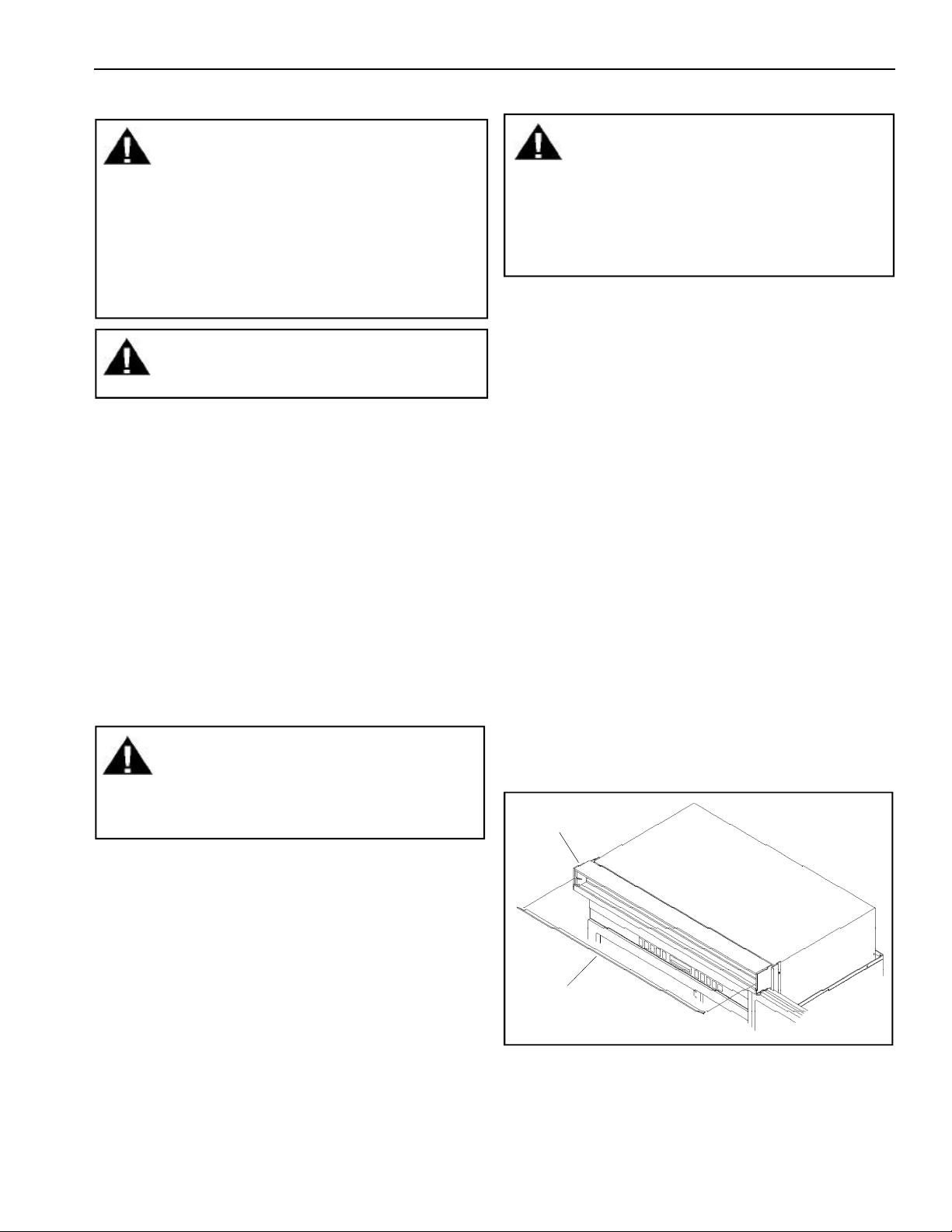
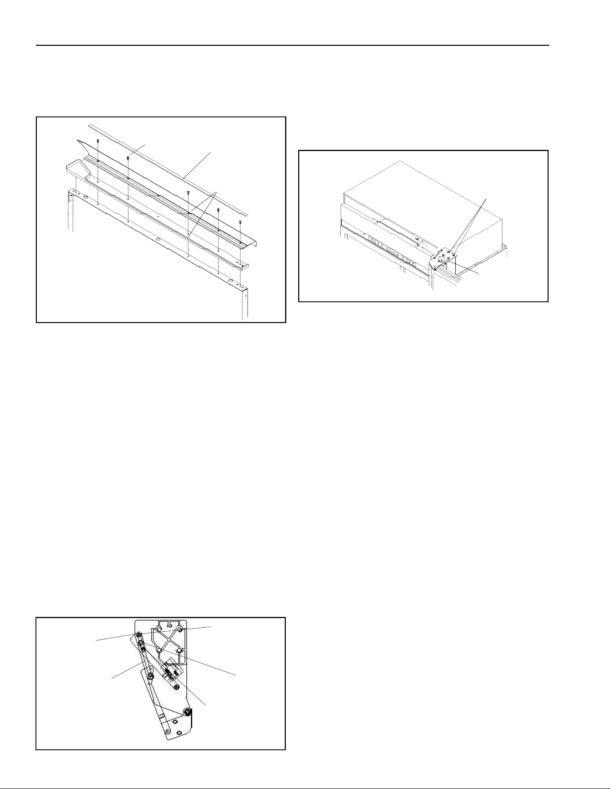
6. Position refrigerator in front of cutout.
7. Remove air grille assembly by lifting center blade.
Air grille
Center air
grille blade
November 1996 5 RS1200001
Page 6
Installation Instructions
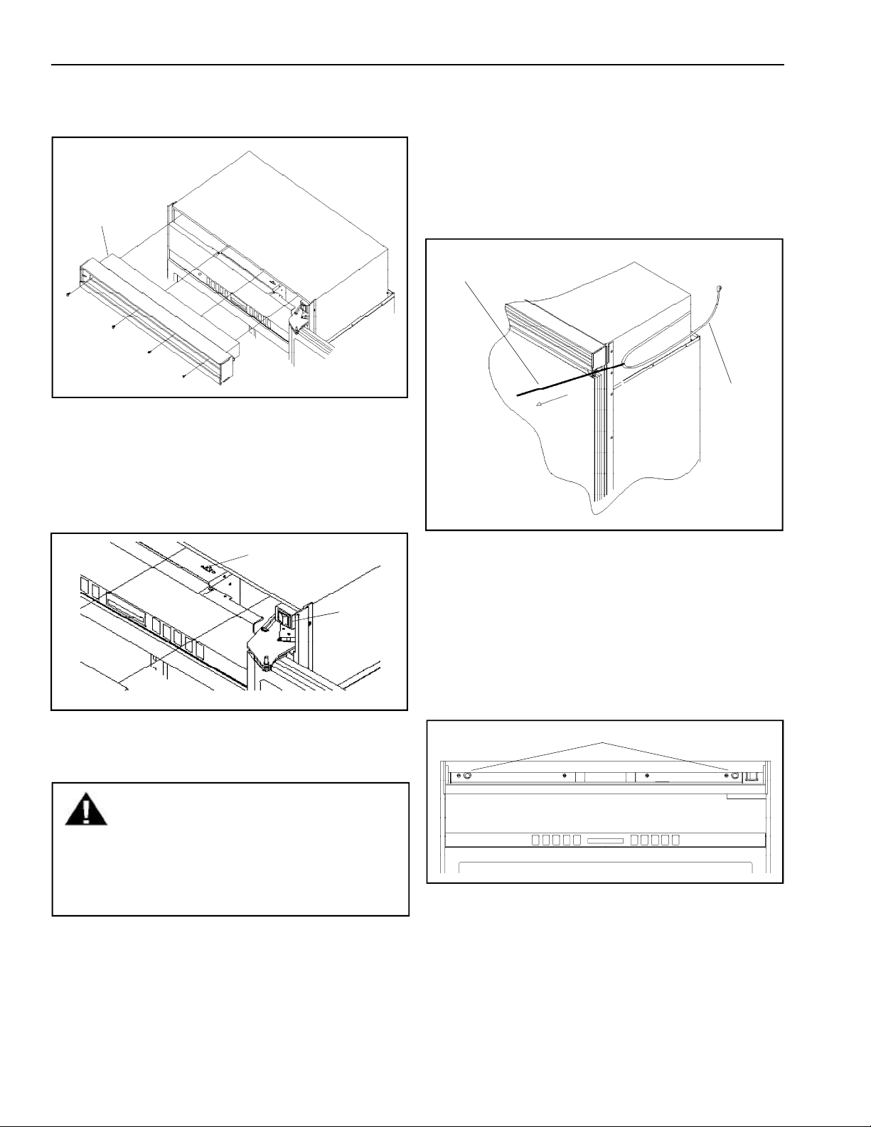
8. Remove (4) 1/4" screws with a magnetic extended
screw driver.
9. Pull air grille assembly forward.
Air grille
assembly
1/4" screws
10. Verify operation by plugging in power cord. Power
switch will be shipped in the on position and the
showroom switch will be shipped in the off position.
Display should flash. Press any key. There is a 6
minute delay before refrigerator starts. Verify
position of each switch if there is no power to
refrigerator.
12. Roll refrigerator into cutout to within 3" of being
flush with kitchen cabinets. To avoid kitchen cabinet
damage, place cardboard between kitchen cabinets
and refrigerator. Push cardboard back with
refrigerator and remove cardboard when refrigerator
is in place. Remove power cord slack by pulling
nylon cord straight out while pushing refrigerator
completely into place. Power and nylon cord will
rest along refrigerator side.
Pull nylon
cord straight
out
Power cord
must rest
as shown
Showroom
switch
Power
switch
11. Pull end of nylon cord around refrigerator side (side
without 1/4" panel installed, if any) level with top of
refrigerator door. Tape cord in place.
WARNING
To avoid electrical shock which can cause
severe personal injury or death, disconnect
power to refrigerator using power switch
before performing any installation procedure.
After performing installation procedure,
connect power using power switch.
13. Level refrigerator by turning front and rear leveling
wheel bolts clockwise to raise refrigerator and
counterclockwise to lower refrigerator. Rotate
stabilizing legs until firmly in place against floor.
14. Align refrigerator with sides of kitchen cabinets
using leveling bolts.
15. Secure lag bolts by removing center air grille blade.
Screw lag bolts securely into 2x4 mounting board
using a magnetic 6" extension socket. See
"Installation Specifications".
Lag bolts
16. Push extra nylon cord back in along side of
refrigerator out of sight or cord can be flush with
refrigerator.
RS1200001 6 November 1996
Page 7
Installation Instructions
Water Connection
The garden hose fitting, compression nut, and sleeve
are located in the literature packet. Amana® Clean
'n Clear™ Bayonet Style Water Filtration System
WF60 is shipped in crisper drawer. See water filter
installation and operating instructions for
specifics.
1. Flush air and impurities from water line by
turning on water supply and running a pint or
more of water into a bucket.
2. Remove plastic cap from water valve fitting.
Connect copper tubing to water valve with
brass nut and brass sleeve. Insert copper tubing
completely into water valve inlet port. Connect
brass nut on copper tubing to water valve inlet
port fitting. Confirm copper tubing is secure by
pulling on copper tubing.
3. Turn on water supply to refrigerator and check
forleaks. Turn off water supply to
refrigerator and correct any leaks. Repeat
this process until no leaks exist. Completely
turn on water supply to refrigerator.
4. Verify drain pan is installed and aligned.
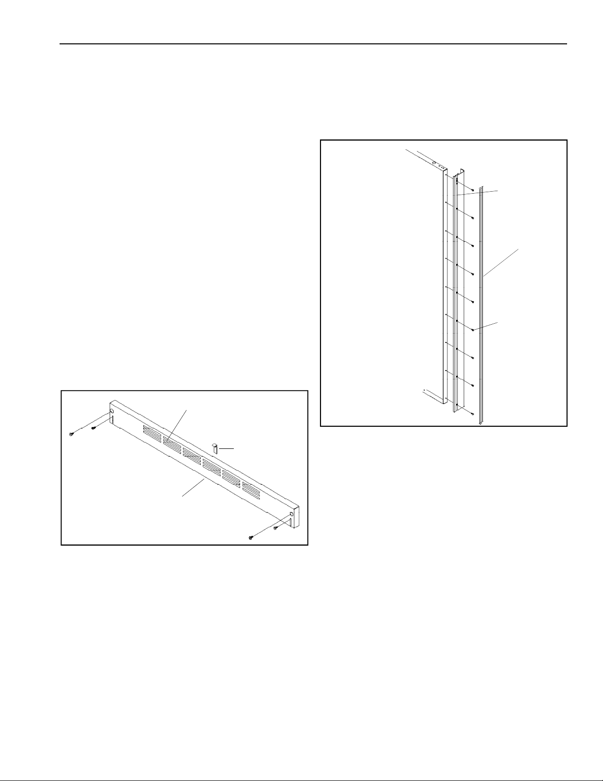
5. Replace toe grille with air vents to the top.
Kitchen flooring must allow toe grille to be
removed. See "Installation Specifications" for
height clearance. See "Custom Finishing
Options" when using a custom toe grille.
Door Panel Installation
Panels must not weigh more than 50 pounds per door.
Refrigerator Door 3/4" Raised Panel
1. Slide out handle screw insert and remove handle
by removing screws with a Phillips
screwdriver.
Handle
Handle screw
insert
Screws
Refrigerator Door
Air vents
Toe grille
Clip
2. Align panel brackets (supplied) with center edge
of panel. Install brackets using 1/4" screws
(supplied).
3. If base panel is less than 1/4" use plastic
shims (supplied). Shims go between bracket and
wood to space panels to desired depth.
4. Drive low profile screws (supplied) with
Phillips screwdriver.
• Panel brackets must be exactly flush to 1/16"
inboard of panel edge.
• For ease of panel installation 2 people are
required to lift and guide panel into trim.
• Install 1 panel at a time.
5. Align panel in trim and push evenly. For
smoother installation apply bar soap on door
trim and refrigerator trim. If panel binds loosen
top or side door trim. Adjust panel and retighten.
6. Install handle with screws. Install screw strip
(supplied) by starting in one corner and pushing
the length of the strip down.
November 1996 7 RS1200001
Page 8
Installation Instructions
Freezer Door 3/4" Raised Panel
1. Slide out handle screw insert and remove handle
by removing screws with a Phillips
screwdriver. Handle is in 2 pieces, reinstall if
pieces come apart.
Screws
Freezer Door
2. 1/2" x 3 1/2" notch is required on hinge side.
3. Remove top handle trim and 1 side trim piece for
ease of installation.
4. Align panel brackets and screws.
5. Align panel in trim and push evenly. Start at one
end and work across. For smoother installation
apply bar soap on door trim and freezer trim. If
panel binds loosen top or side door trim. Adjust
panel and retighten.
6. Install handle with screws. Install screw strip
(supplied) by starting in one corner and pushing
the length of the strip down.
Handle screw
insert
Handle
Door Stop Adjustment
1. Remove center grille blade from top air grille.
2. Remove top air grille by removing (4) 1/4” screws
with a magnetic screw driver. Pull assembly
forward.
3. Open refrigerator door so door stop arm and
shoulder screw are accessible. Shoulder
screws should be in 110° door opening position.
4. Remove shoulder screw and place shoulder
screw
in the 90° or 120° door opening position.
Hinge Adjustment
Verify proper door alignment. Wait until panels are
installed for door settlement. Only the top hinge is
adjustable.
Adjust top hinge by completing the following:
1. Remove air grille blade and air grille assembly.
2. Loosen top hinge screws.
Top hinge
screws
Top hinge
3. Align refrigerator door by lifting.
4. Tighten screws.
5. Install air grille.
6. Replace air grille assembly.
Interior Setup
1. Remove interior packaging.
2. Turn shelves upright.
3. Move dairy module to desired position on
refrigerator door. See "Model Diagram".
4. Twist cardboard in ice bin to release freezer
tray.
5. Remove literature packet from freezer tray and
give to consumer. Complete "Installation
Checklist" with consumer.
Shoulder
screw
Door stop arm
RS1200001 8 November 1996
120° door
opening
position
110° door
opening
position
90° door
opening
position
Page 9

Sound Information
Normal Operating Sounds
This new refrigerator may be replacing a differently
designed, less efficient or smaller refrigerator.
Today’s refrigerators have new features and are more
energy efficient. As a result, certain sounds may be
unfamiliar. These sounds are normal and will soon
become familiar. These sounds also indicate the
refrigerator is operating and performing as designed.
• Freezer and fresh food fan air rushes and whirs.
• Sealed system (evaporator and heat exchanger)
refrigerant flow gurgles, pops or sound like boiling
water.
• Defrost heater sizzles, hisses or pops.
• Condenser fan air rushes and whirs.
• Compressor has a high pitched hum or pulsating
sound.
• Ice cubes from ice maker drop into ice bucket.
• Ice maker water valve hookup buzzes when ice
maker fills with water. This occurs whether or not
refrigerator is connected to water supply. If
refrigerator is not connected to water supply, stop
sound by raising ice maker arm to off position.
• Foam insulation is very energy efficient and has
excellent insulating capabilities. However, foam
insulation is not as sound absorbent as previously
used fiberglass insulation.
November 1996 9 RS1200001
Page 10

System Diagnosis
Pressure and Relationship Chart
Condition Suction
Refrigerant
Overcharge
Refrigerant
Shortage
Partial
Restriction
Air in System
Low Ambient
Installation
(Reverse for
High Ambient
Installation)
Additional
Heat Load
Pressure
Variation
from Normal
Increase Increase War mer War mer Colder Increase
Decrease
Decrease
Near Normal Increase War mer War mer Warmer Increase
Decrease Decrease Colder Warmer Warmer Decrease
Increase Increase War mer War mer Warmer Increase
Head Pressure
Variation from
Normal
Decrease or Increase
See "Refrigerant
Shortage Symptoms"
Decrease or Increase
See "Restriction
Symptoms"
T1 Inlet
Temperature
Variation from
Normal
Colder Warmer Warmer Decrease
Colder Warmer Warmer Decrease
T2 Outlet
Temperature
Variation from
Normal
T3 Suction
Temperature
Variation from
Normal
Variation from
Wattage
Normal
Inefficient
Compressor
Increase Normal or Decrease Warmer or Colder War mer Warmer Decrease
RS1200001 10 November 1996
Page 11

System Diagnosis
Refrigerant Overcharge Symptoms
• Above normal freezer temperature.
• Compressor running continuously.
• Freezing in refrigerator due to Chef’s Pantry
.• High suction and head pressure.
• High wattage.
• Warm evaporator inlet and outlet temperature.
• Below ambient suction tube temperature. Check for
separated heat exchanger when suction temperature
is colder than ambient.
• Refrigerant will flood out causing suction line to frost
or sweat, if defrost system fails and cooling coil is not
defrosted. Correct problem instead of purging
refrigerant.
• Freezer colder than necessary (normal package
temperature is 0° to 2°F).
• Evaporator fan motor not running.
™
Refrigerant Shortage Symptoms
• Rise in refrigerator and freezer temperatures.
Warm beverages will be first indication of
possible refrigerant shortage. Frozen meats and
vegetables will not thaw immediately. Some freezing
may occur in refrigerator section due to additional run
time because of Chef’s Pantry™. Capillary line will not
have full column of liquid with refrigerant shortage. A
noticeable hissing sound in evaporator will be heard.
Hissing should not be mistaken for regular refrigerant
boiling sounds.
• Long or continuous run time.
• Traces of oil caused by leak or cracked refrigerant
line.
• Lower than normal wattage.
• Compressor will feel hot due to heat generated by
motor windings from continuous running. Compressor
will not be as hot as it would be with full charge and
long run times caused by reasons such as dirty
condenser.
• Condenser will feel room temperature.
• Capillary tube will feel warmer than normal.
• If high side leak, both gauges will show lower than
normal readings. As charge becomes less, readings
will lower. Suction pressure gauge will probably
indicate a vacuum.
• If low side leak, suction pressure gauge will show
lower than normal readings, probably in a vacuum.
Head pressure gauge will show higher than normal.
Readings will probably rise because of air drawn in
through leak is compressed by compressor and
accumulates in high side (condenser) of system.
• Partial frosting of evaporator.
Restriction Symptoms
• Refrigeration cooling occurs on low pressure side of
partial restriction.
• Total restriction will stop circulation of refrigerant and
no cooling will occur.
• Touch refrigeration lines. Most common place for
restriction is at drier filter or capillary tube inlet or
outlet.
• If partial restriction there will be temperature
difference at restriction point. Evaporator side will be
cooler. In most cases, frost and/or condensation will
be present. Longer time is required for system to
equalize.
• Kinked line will cause restriction. Visually check entire
system for kinks.
• Slight restriction will give same indications as
refrigerant shortage with lower than normal back
pressure, head pressure, wattage, and warmer
temperatures.
• If total restriction is on discharge side of compressor,
higher than normal head pressures and wattages will
occur. This is only true while low side is being pumped
out and if restriction was between compressor and
first half of condenser.
Diagnose restriction by completing the following:
1. Discharge system.
2. Replace drier-filter.
3. Evacuate and recharge system with specified
refrigerant charge.
If refrigerator performs normally, the following
conditions may exist:
• refrigerant loss
• partially restricted drier
• moisture in system
If refrigerator performs as previously described,
capillary line or condenser may be restricted. Locate
and correct restriction point.
Restriction reduces refrigerant flow rate and heat
removal rate. Total restriction may be caused by
moisture, poorly soldered joint, or solid contaminants
in system. Moisture freezes at evaporator inlet end of
capillary tube. Solid contaminants collect in drier.
Wattage drops because compressor is not circulating
normal amount of refrigerant.
If restriction is on low side suction, pressure will be in
a vacuum and head pressure will be near normal. If
restriction is on high side, suction pressure will be in a
vacuum and head pressure will be higher than normal
during pump out period. In both cases, it will take
longer than 10 minutes for head pressure to equalize
with low side after compressor stops.
November 1996 11 RS1200001
Page 12

System Diagnosis
Air in System Symptoms
Air in system can be caused by low side leak or
improper servicing. If low side leak occurs,
temperature control will not achieve temperatures
and compressor will run continuously. Compressor
will eventually pump low side into a vacuum, drawing
air and moisture into system. Air and R134a do not
mix. Air pressure will be added to normal head
pressure, resulting in higher than normal head
pressures.
Determine if air is present by reading head pressure
gauge with refrigerator off and evaporator and
condenser at same temperature. Verify temperature
on condenser outlet tube. Temperature should be
within 3° or 4°F of what "Pressure and Temperature
Relationship Chart" shows for a given idle head
pressure. If temperature of condenser outlet is
considerably lower than idle head pressure of gauge,
air is in system.
Diagnose air in system by completing the following:
1. Thoroughly check for leaks.
2. Correct leak source. Do not attempt to purge air
off. This could result in an undercharged system.
3. Discharge system.
4. Replace drier-filter.
5. Evacuate and recharge system with specified
refrigerant charge.
When ambient temperature is below cut-in of
temperature control, compressor will not operate.
Drain traps will freeze in ambient temperatures of
32°F.
Heat Load Symptoms
Increased heat load can result from addition of large
supply of foods, excessive door openings, poor door
sealing, interior light remaining on, etc.
Increased heat being absorbed by refrigerant in
evaporator will affect temperature and pressure of
gas returning to compressor. Refrigerator and freezer
temperatures, power consumption, discharge, and
suction pressures are all affected by heat load.
Pressures will be higher than normal under heavy
heat load.
Low or High Ambient Temperature
Installation Symptoms
Lower ambient air temperature reduces condensing
temperature and temperature of liquid entering
evaporator. Increase in refrigeration due to operation
in lower ambient results in decrease in power
consumption and run time. At lower ambients there is
reduction in cabinet heat leak which is partially
responsible for lower power consumption and run
time.
An increase in refrigeration will not occur below
certain minimum ambient temperature. Temperature
varies with type and design of refrigerator.
Ambient temperatures lower than 55°F will affect
efficiency. The higher the ambient temperature, the
higher the head pressure must be to raise the high
side refrigerant temperature above condensing
medium. Head pressure will be higher as ambient
temperature raises. Refrigerators installed in ambient
temperatures lower than 55°F will not perform
effeciently because system pressures are generally
reduced and unbalanced. Lower head pressure forces
less liquid refrigerant through capillary line, resulting
in symptoms of refrigerant shortage. The lower the
ambient temperature, the more pronounced the
condition.
RS1200001 12 November 1996
Page 13
HFC134a Service Information
HFC134a is alternative refrigerant for CFC12.
HFC134a has an ozone depletion potential (ODP)
factor of 0.0 and a global warming potential (GWP)
factor of 0.27. HFC134a is not flammable and has
acceptable toxicity levels. HFC134a is not
interchangeable with CFC12. There are significant
differences between HFC134a and CFC12 which
must be considered when handling and processing
refrigeration system.
Health, Safety, and Handling
Health, safety and handling considerations for
HFC134A are virtually no different than those for
CFC12.
Health, Safety, and Handling CFC12 HFC134a
Allowable overall exposure limit 1,000 ppm Same
Vapor exposure to skin No effect Same
Liquid exposure to skin Can cause frostbite Same
Vapor exposure to eye Very slight irritant Same
Liquid exposure to eye Can cause frostbite Same
Above minimum exposure limit Can cause Asphyxiation, Same
Tachycardia, and Cardia
Arrhythmias
Safety and handling Wear appropriate skin and eye Same
protection. Use with adequate
ventilation.
Spill management Remove or extinguish ignition or Same
combustion sources. Evacuate
or ventilate area.
Fire and explosion hazards May decompose if contact with
flames and heating elements.
Container may explode if heated
due to resulting pressure rise.
Combustion products are toxic.
Storage conditions Procedures/rules for CFC12 Same
also apply for HFC134a
Disposal procedures Recycle or reclaim Same
Comparison of CFC12 and HFC134a
Properties
Properties/Characteristics CFC12 HFC134a
Ozone Depletion Potential (ODP) 1.0* 0.0*
Global Warming Potential (GPW) 3.2* 0.27*
Molecular weight 121 102
Boiling point at 1 atmosphere -22°F (-30°C) -15°F (-26°C)
Vapor pressure at 77°F (25°C) 80 psig 82 psig
Liquid density at 77°F (25°C) 82 lb/ft3 75 lb/ft3
Flammability No No
High-side system operating HFC134a approximately 3 psig
Pressure at 65°F (18°C) ambient higher than CFC12
Low-side system operating HFC134a approximately 2 psig
Pressure at 65°F (18°C) ambient lower than CFC12
* Compared to CFC 11 = 1
Caution
To minimize contamination, exercise extreme
care when servicing HFC134A sealed systems.
• No trace of other refrigerants is allowed in HFC134a
systems. Chlorinated molecules in other refrigerants
such as CFC12, etc. will lead to capillary tube
plugging.
• Ester oil is used in HFC134a systems. Do not use
mineral oil. HFC134a and mineral oils cannot be
mixed. If mineral oils were used in HFC134a systems,
lubricant would not return to compressor and would
cause early compressor failure. If significant amount
of oil has been lost from compressor, replace oil
rather than adding oil.
• Ester oils used in HFC134a systems are so
hydroscopic that by the time an inadequate system
performance is detected, oil will be saturated with
moisture.
• CFC12 has much higher tolerance to system
processing materials, such as drawing compounds,
rust inhibitors, and cleaning compounds, than
HFC134a. Such materials are not soluble in HFC134a
systems. If materials were to be washed from system
surfaces by ester oils, they could accumulate and
eventually plug capillary tube.
• Care must be taken to minimize moisture from
entering HFC134a system. Do not leave compressor
or system open to atmosphere for more than 10
minutes. Excessive moisture in HFC134a system will
react with compressor oil and generate acid.
• Compressor must be replaced when performing low
side leak repair.
• Drier filter must always be replaced with service drier
filter, part #B2150504.
Important: Unbrazing drier filter from tubing will drive
moisture from desiccant and into system, causing
acids to form. Do not unbraze filter drier from tubing.
If CFC12 service drier was installed in HFC134A
system, drier could overload due to excessive
moisture.
• HFC134a compatible copper tubing, part
#R0174075 (1/4" O.D. X 18" length) and part
#R0174076 (5/16" O.D. X 24" length) must be used
when replacing tubing.
• Avoid system contamination by using Towerdraw
E610 evaporating oil, part # R0157532, when flaring,
swaging, or cutting refrigeration tubing.
November 1996 13 RS1200001
Page 14
Service Equipment
HFC134a Service Information
Listed below is equipment needed for proper
servicing of HFC134a systems. Verify equipment is
confirmed by manufacturer as being compatible with
HFC134a and ester oil system.
Equipment must be exclusively used for HFC134a.
Exclusive use of equipment only applies to italic
items.
• Evacuation pump
Check with vacuum pump supplier to verify
equipment is compatible for HFC134a. Robinair,
Model 15600, 2 stage, 6 cubic feet per minute pump
is recommended.
• Four-way manifold gauge set, with low loss hoses
• Leak detector
• Charging cylinder
• Line piercing saddle valve
(Schroeder valves). Seals must be HFC134a and
ester oil compatible. Line piercing valves may be used
for diagnosis but are not suitable for evacuation or
charging, due to minute holes pierced in tubing. Do
not leave mechanical access valves on system.
Valves eventually will leak. Molecules of HFC134a are
smaller than other refrigerants and will leak where
other refrigerants would not.
• Swaging tools
• Flaring tools
• Tubing cutter
• Flux
• Sil-Fos
• Silver solder
• Oil for swaging and flaring
Use only part #R0157532
• Copper tubing
Use only part #R0174075 and #R0174076
• Dry nitrogen
99.5% minimum purity, with -40°F or lower dew point
• Crimp tool
• Tube bender
• Micron vacuum gauge
• Process tube adaptor kit
• Heat trap paste
• ICI appliance grade HFC134a
Drier Replacement
Prior to opening refrigeration system, recover
HFC134a refrigerant for safe disposal.
Every time sealed HFC134a system is repaired, drier
filter must be replaced with, part # B2150504.
Cut drier out of system by completing the following
steps. Do not unbraze drier filter. Applying heat to
remove drier will allow moisture into system.
1. Score capillary tube close to drier and break.
2. Reform inlet tube to drier allowing enough space
for large tube cutter.
3. Cut circumference of drier at 1-1/4", below
condenser inlet tube joint to drier.
4. Remove drier.
5. Apply heat trap paste on post condenser tubes to
protect grommets from high heat.
6. Unbraze remaining part of drier. Remove drier
from system.
7. Discard drier in safe place. Do not leave drier with
customer. If refrigerator is under warranty, old
drier must accompany warranty claim.
DANGER
To avoid death or severe personal injury, cut
drier at correct location. Cutting drier at incorrect
location will allow desiccant beads to scatter.
Completely clean area of beads, if spilled.
RS1200001 14 November 1996
Page 15
HFC134a Service Information
Replacement Service Compressor
HFC134a service compressors will be charged with
ester oil and pressurized with dry nitrogen. Before
replacement compressor is installed, pull out 1 rubber
plug. A pop from pressure release should be heard. If
a pop sound is not heard, do not use compressor.
Positive pressure in compressor is vital to keep
moisture out of ester oil. Do not leave compressor
open to atmosphere for more than 10 minutes.
Compressor Testing Procedures
• Refer to “Temperature and Relationship Chart” for
operating watts, test points, and temperature
relationship test.
• Temperature testing is accomplished by using 3 lead
thermocouple temperature tester in specific locations.
Test point T-1 is outlet on evaporator coil and T-2 is
inlet. Test point T-3 is suction tube temperature
midway between where armaflex ends and suction
port of compressor (approximately 12 inches from
compressor).
• Thermocouple tips should be attached securely to
specified locations.
• Do not test during initial pull down. Allow one off cycle
or balanced temperature condition to occur before
proceeding with testing.
• Refrigerator must operate minimum of 20 minutes
after thermocouples are installed.
• Turn control to colder to obtain required on time.
• Wattage reading must be recorded in conjunction with
temperature test to confirm proper operation.
• Suction and head pressures are listed on
“Temperature and Relationship Chart” Normally these
are not required for diagnosis but used for
confirmation on systems which have been opened.
WARNING
To avoid death or severe personal injury, never
use oxygen, air or acetylene for pressure testing
or cleanout of refrigeration system. Use of
oxygen, air, or acetylene may result in violent
explosion. Oxygen may explode on contact with
oil and acetylene will spontaneously explode
when under pressure.
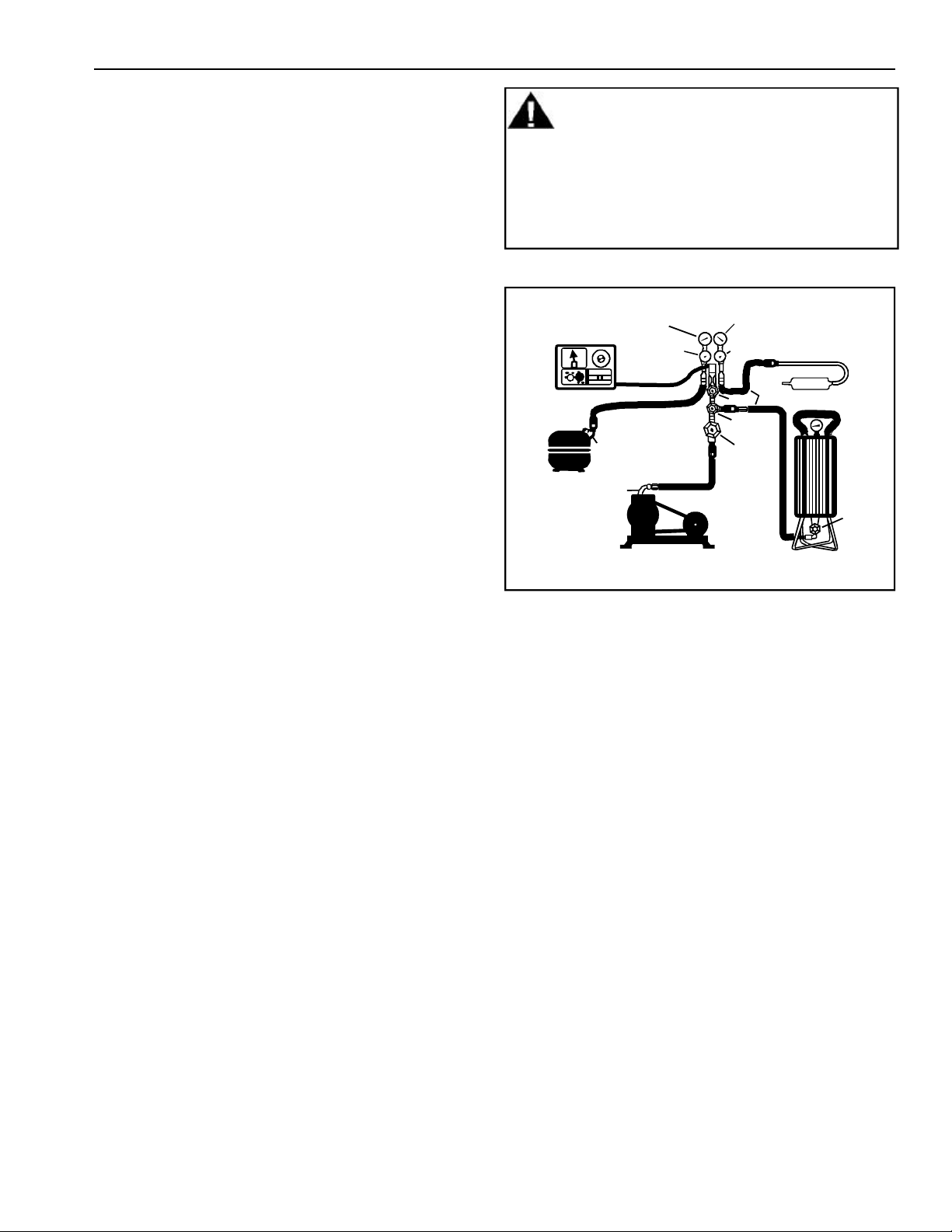
Evacuation and Charging
Thermistor
Vacuum Gauge
Compressor
Low Side Gauge
Charging Hose
Compressor
Process
Tube
.6 cm Copper
Tubing
E
Valve
Vacuum Pump
High Side Gauge
D
Valve
Charging Hose
C
B
A
Drier/Process Tube
F
Valve
Charging
Cylinder
Refrigerant Charge
Refrigerant charge in all capillary tube systems is
critical and exact amount is required for proper
performance. Factory charges are shown on serial
plate. Do not use refrigerant other than shown on
serial plate.
Leak Testing
Undetected leaks lead to repeated service calls and
eventually result in system contaminations,
restrictions, and burned out compressors.
After recharging, sealed system must be thoroughly
tested for leaks. If a very small leak is difficult to
isolate, coat area with soap suds and observe
location of bubbles.
November 1996 15 RS1200001
Page 16

HFC134a Service Information
WARNING
To avoid severe personal injury or death from
fire keep system free from contamination due
to presence of air. Follow instructions exactly.
Before opening system evaporator coil must be at
ambient temperature to minimize moisture infiltration
into system.
1. After capturing refrigerant, replacing drier and
making any repairs, evacuate system from high
side through drier/process tube and low side
through compressor process tube simultaneously.
Evacuation should not be done through line
piercing valve but through I.D. opening of tubes.
2. With valves “C” and “F” closed to thermistor
vacuum gauge and charging cylinder, open all
other valves and start vacuum pump.
3. At approximately 29 inches of vacuum, open valve
“C” to thermistor vacuum gauge and take micron
reading.
4. Continue evacuating system until thermistor
vacuum gauge registers 600 microns.
5. At 600 microns close valve “A” to vacuum pump to
allow micron reading in system to balance. Micron
level will rise. If in 2 minutes, micron level
stabilizes at 1000 microns or below, system is
ready for charging.
• If micron rises above 1000 micron level and
stabilizes, open valve “A” to vacuum pump and
continue evacuating.
• If micron reading rises rapidly and does not
stabilize, a leak still exists in system. Close valve
“A” to vacuum pump and “C” to thermistor vacuum
gauge. Invert charging cylinder and open charging
cylinder valve “F” to add partial charge for leak
checking. With leak detector, check manifold
connections and system for leaks. After locating
leak, capture refrigerant charge, repair leak, and
begin at step 1.
6. Once system is ready to charge, close valve “A”
(vacuum pump), “C” (thermistor vacuum gauge),
and “E” (low side manifold gauge).
7. Check serial plate for correct charge and set scale
on dial-a-charge cylinder for corresponding
HFC134a pressure reading. Do not use captured or
recycled refrigerant in Amana® refrigerators. Use
of captured or recycled refrigerant voids any
warranty.
8. Open valve “F” to charging cylinder and let exact
amount of refrigerant out of cylinder. Close valve.
Low side gauge pressure should rise shortly after
opening charging cylinder valve as system
pressure equalizes through capillary tube. If
pressure does not equalize, a restriction typically
exists at capillary/drier braze joint.
9. If no restriction exists, open valve “E” (low side
manifold gauge) and pinch off high side drier
process tube.
10. Start compressor and draw remaining refrigerant
in charging hoses and manifold into compressor
through compressor process tube. To check high
side pinch-off drier process tube, close valve “D”
(high side gauge). If pinch-off is not leaking, high
side pressure will not rise. If high side pressure
gauge shows an increase, repeat high side pinchoff and open valve “D”. Repeat until high side
pinch-off no longer leaks.
11. Pinch-off compressor process tube and remove
charging hose. Braze stub closed while
compressor is operating.
12. Unplug refrigerator from electrical outlet.
Remove charging hose and braze high side drier
process tube closed.
RS1200001 16 November 1996
Page 17
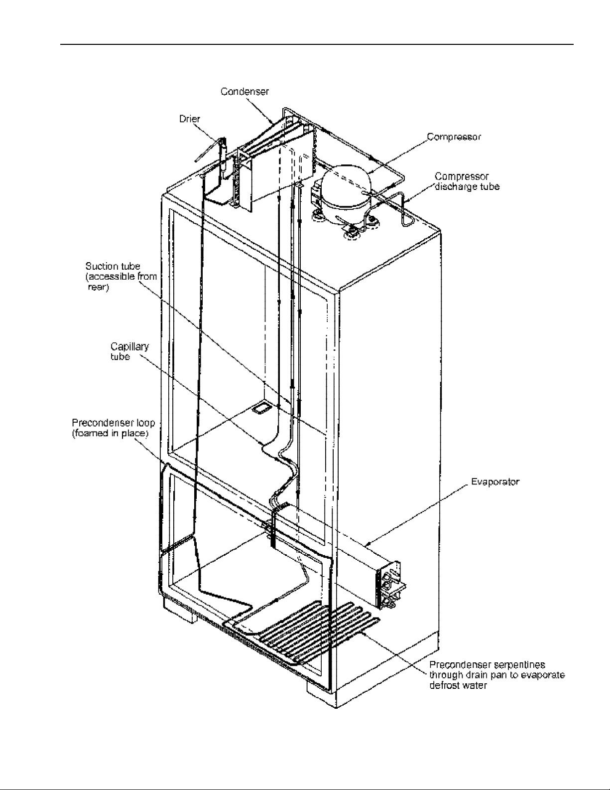
Refrigerant Flow
November 1996 17 RS1200001
Page 18
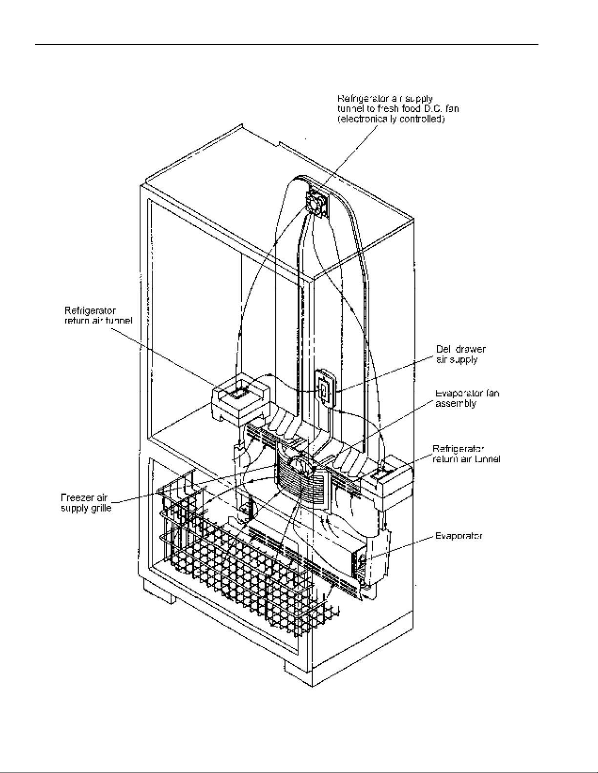
Air Flow
RS1200001 18 November 1996
Page 19
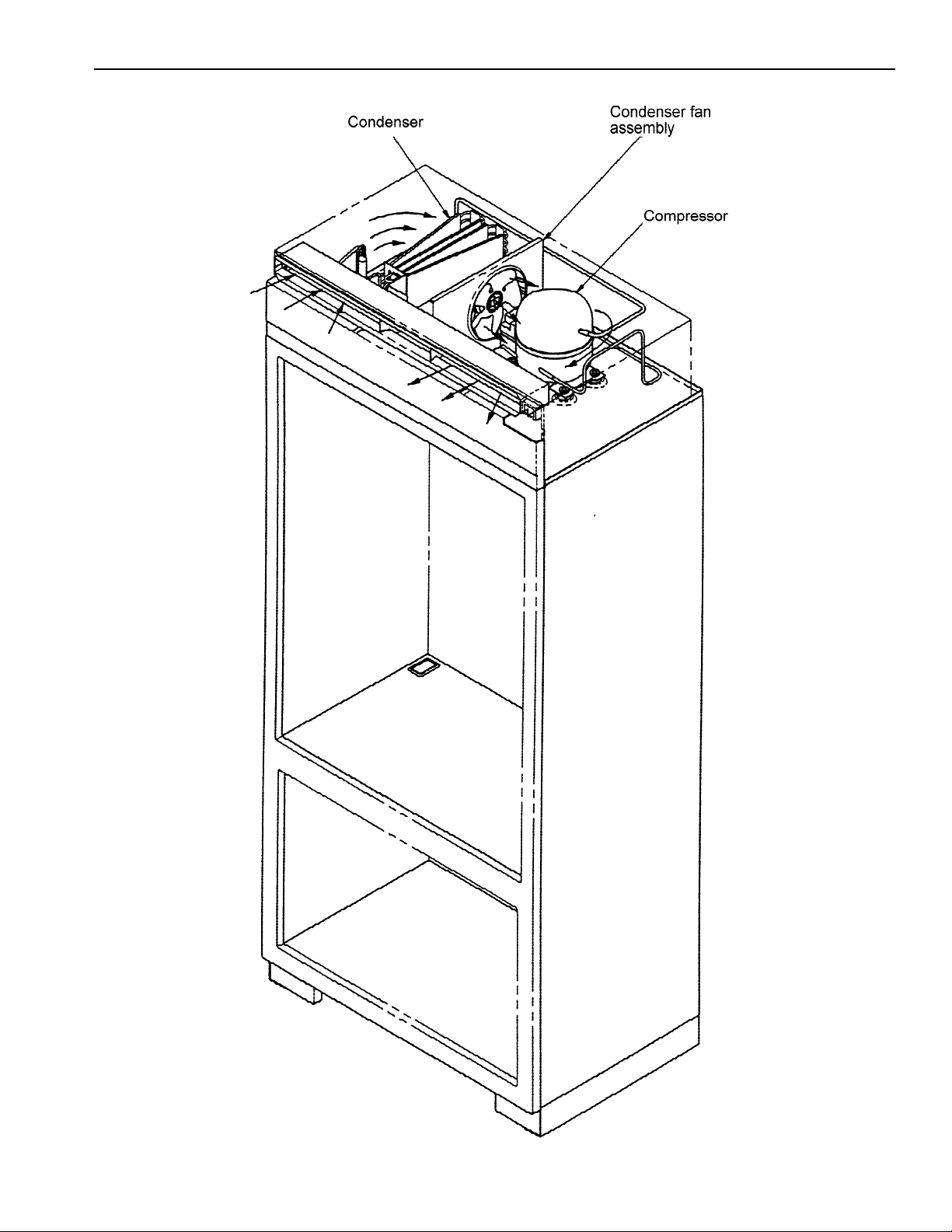
Machine Compartment Assembly
November 1996 19 RS1200001
Page 20
Component Function and Testing
start winding current causes PTC relay to heat. After an
Capacitor Run capacitor connects to relay terminal.
Capillary tube
Capillary is sized in diameter and length to
feed proper amount of refrigerant to
evaporator.
Capillary is soldered to suction line to transfer
heat from capillary and add additional
superheat to gas refrigerant in compressor
suction line.
WARNING
To avoid electrical shock which can cause severe personal
injury or death, discharge capacitor through a resistor before
handling.
1. Disconnect power to refrigerator.
2. Remove capacitor and disconnect capacitor wires.
3. Discharge capacitor by shorting across terminals with a resistor for
1 minute.
4. Check resistance across capacitor terminals with ohmeter set on
"X1K" scale.
• Needle should jump towards 0 ohms and quickly move back to
infinity.
• If needle does not move, the capacitor is open.
• If needle reads a constant value at or near 0 ohms, the capacitor is
shorted.
• If needle jumps towards 0 and then moves back to a constant high
resistance (not infinity), the capacitor has a high resistance leak.
Capillary discharges into evaporator.
Compressor When compressor electrical circuit is energized, the
amount of starting time the start winding circuit turns
off. PTC relay will switch off the start winding circuit
even though compressor has not started (as when
attempting to restart after momentary power
interruption).
With "open" PTC relay, compressor will not start
because there is little or no current to start windings.
Overload protector will open due to high locked rotor
run winding current.
With "shorted" PTC relay or capacitor, compressor will
start and overload protector will quickly open due to
high current of combined run and start windings.
With open or weak capacitor, the compressor will start
and run as normal but will consume more energy.
Check for resistance between:
Terminals "S" & "C"
Terminals "R"& "C"
Ground Test
Disconnect power to refrigerator .Remove compressor leads and use an
ohmmeter set on highest scale. Touch 1 lead to compressor body (clean
point of contact) and the other probe to each compressor terminal. If a
reading is obtained, compressor is grounded and must be replaced.
Operation Test
If motor winding tests fail to show cause for failure:
1. Disconnect power to refrigerator. Wire a test cord to disconnect
switch.
2. Place time delayed fuse, with U.L. rating equal to amp rating of motor,
in test cord socket.
3. Remove overload and relay.
4. Connect start, common, and run leads of test cord on appropriate
terminals of compressor.
5. Attach capacitor leads of test cord together. If capacitor is used,
attach capacitor leads to a good capacitor of same capacity.
6. Plug test cord into volt-watt meter to determine start and run wattage
as well as check for low voltage which can also be a source of
trouble.
7. With power to volt-meter, press start cord switch and release. If
compressor motor starts and draws normal wattage compressor is
okay and trouble is in capacitor, relay, overload, freezer temperature
control, adaptive defrost control, or elsewhere.
RS1200001 Rev. 1 20 April 1998
Page 21
Component Function and Testing
where as gas temperature is reduced, gas condenses
into high pressure liquid state. Heat transfer takes place
restrict normal air movement throughout the condenser.
To avoid severe personal injury or death observe the following:
refrigeration systems without a reliable pressure regulator and
See “Ice Maker” section for service information.
Condenser
Condenser is a tube and wire construction located in
compressor compartment. Condenser is on high
pressure discharge side of compressor.
Refrigerant flows from compressor into a precondenser serpentine below drain pan to evaporate
defrost water. From serpentine, refrigerant flows into
pre-condenser loop (Yoder loop) foamed around
freezer door opening to help control external
condensation around freezer door and on flange.
Higher pressure refrigerant gas is routed to condenser
because discharged gas is at higher temperature than
air that is passing over condenser.
Condenser is air cooled by fan motor. It is very
important that adequate air flow over condenser is
maintained. If efficiency of heat transfer from
condenser to surrounding air is impaired, condensing
temperature becomes higher. Higher temperature liquid
means less heat will be removed during boiling in
evaporation. This is indicated by higher that normal
head pressures, long run time, and high wattage.
Remove any lint, dust accumulation, etc. that would
• Leaks in condenser can usually be detected by using an electronic
leak detector or soap solution. Look for signs of compressor oil when
checking for leaks. A certain amount of compressor oil is circulated
with refrigerant.
• Leaks in post condenser loop are rare as loop is a 1 piece copper
tube.
• In cases of minute leaks it may be necessary to separate condenser
from rest of refrigeration system and pressurize condenser up to a
maximum of 235 PSI with a refrigerant and dry nitrogen combination.
WARNING
• Protect against a sudden eruption if high pressures are
required for leak checking.
• High pressure compressed cases should never be used in
pressure relief valve in the lines.
Drier
Evaporator
Heater,
evaporator
(defrost)
Ice Maker
Desiccant
(20) 8 X 12 4AXH - 7 M.S. - Grams
Inner volume of evaporator allows liquified refrigerant
discharged from capillary to expand into refrigerant
gas.
Act of expansion cools evaporate tube and fin
temperature to approximately -20°F, transfering heat
from freezer section to refrigerant.
Passing through suction line to compressor, the
refrigerant picks up superheat (a relationship between
pressure and temperature that assures complete
vaporization of liquid refrigerant) as result of capillary
being soldered to suction line.
Refrigerant gas is pulled through suction line by
compressor to complete refrigerant cycle.
See "Electronic Functional Description, Adaptive
Defrost Circuitry"
Drier is placed at P.C. loop outlet and passes liquified refrigerant to
capillary.
Drier must be changed whenever sealed refrigeration system is opened.
Drier used in R12 sealed system is not interchangeable with drier used in
R134a sealed system. Replace drier with part #B2150504.
Leaks in evaporator can usually be detected by the use of electronic leak
detector or soap solution. Compressor oil is circulated with refrigerant so
look for oil when checking for leaks.
For minute leaks separate condenser from rest of refrigeration system
and pressurize condenser up to a maximum of 140 PSI with a refrigerant
and dry nitrogen combination. Recheck for leaks.
Check resistance across heater.
Check defrost system by thermocoupling defrost thermostat and plugging
refrigerator in wattmeter. Force into defrost mode. Wattmeter should read
specified watts (according to tech sheet) ± 20 watts. When defrost
thermostat reaches specified temperature (according to tech sheet) ±
5°F., thermostat should interrupt power to heater.
April 1998 21 RS1200001 Rev.1
Page 22

Component Function and Testing
Condenser fan moves cooling air across condenser coil
female pin receptacle terminal which pushes onto compressor common
After a short time, current will have heated the resistor
Solid state relay plugs directly on compressor start and
within relay. Run capacitor is connected to relay
Switch
Continuity
Motor,
condenser psc
Motor, ecm
evaporator fan
Motor,
refrigerator fan
Overload
and compressor body.
The condenser motor is in a parallel circuit with the
compressor.
Evaporator motor moves air across evaporator
coil and throughout refrigerator.
Evaporator fan motor is in a parallel circuit with
compressor, with a delay for warm coil
conditions.
Refrigerator fan circulates cold air into refrigerator
compartment.
The refrigerator fan motor is in a series circuit with the
semi conductor switch.
Overload is a temperature and current sensing type.
Overload opens when sensing a high current or high
compressor temperature.
Check resistance across coil.
Check resistance from ground connector solder. Trace to motor frame
must not exceed .05 ohms. Check power at connector to evaporator
motor.
See "Refrigeration and Defrost Component Checks Made at High Voltage
Board" section for D.C. voltage check at high voltage board. Check for
voltage at motor also.
1. Disconnect power to refrigerator.
2. Remove relay cover and pull relay off compressor.
3. Pull overload protector off compressor common terminal.
3. With ohmmeter, check resistance between 1/4 " male terminal and
After overload opens, overload can require up to 2
hours to reset, depending on ambient temperature and
residual heat load in compressor.
Relay, PTC With power off check resistance.
Switch,
keyboard
When voltage is connected and PTC is cooled, current
passes through PTC to the start winding.
in PTC and resistance will rise. This blocks current
flow through PTC.
Start winding remains in the circuit through the run
capacitor.
run terminals. Relay terminals 2 and 3 are connected
terminal 3. The L2 side of 120 VAC power is
connected to relay terminal 2.
terminal. At ambient temperature, overload protector should have less
than 1 ohm resistance. An open overload protector will have infinite
resistance.
Across terminals 2 & 3:
Normal = 3 to 12 ohms
Shorted = 0 ohms
Open = infinite ohms
Functions
Display On 1 and 3
Freezer Temp 3 and 6
Ref Temp 3 and 7
Warmer 6 and 7
Colder 4 and 6
Vacation 4 and 7
Max Ref 7 and 8
Max Frz 4 and 8
Alarm Off 4 and 5
Display Off 5 and 8
Test
RS1200001 Rev. 1 22 April 1998
Page 23

Component Function and Testing
Switch,
icemaker
interlock, no
Switch, light nc Completes circuit to turn on light when refrigerator or
COM
NO
NC
Switch, power
DPST
3
2
6
5
Switch,
showroom,
SPDT
Opens circuit to icemaker when freezer door is open to
prevent cycle while door is open.
freezer door is opened.
Shuts off all power to refrigerator when switch is off
(open). Refrigerator is shipped with switch on.
1
4
On position completes power to lights and display only.
Off position completes circuit for normal operation.
Check resistance across terminals with:
Switch arm depressed Closed
Switch arm not depressed Open
Check resistance across terminals with
Switch arm depressed Open
Switch arm not depressed Closed
Check resistance across terminals with:
Switch off (open) no continuity between 1 and 2, 4 and 5
Switch on (closed) continuity between 1 and 2, 4 and 5
Check resistance at test points:
Showroom operation - E3, at high voltage board to pin 3 (blue/white wire)
at high voltage wire harness.
Unit run - E9, at high voltage board to pin 3 (blue/white wire) at high
voltage wire harness.
Switch, slide Check resistance across terminals
Switch up
Middle terminal to top terminal 0 Ohms
Middle terminal to lower terminal Infinite Ohms
Switch down
Middle terminal to top terminal Infinite Ohms
Middle terminal to lower terminal
Switch, light Completes light circuit when freezer door is open. Check resistance across terminals with:
Switch arm depressed Open
Switch arm not depressed Closed
Thermistor Senses temperatures within refrigerator and freezer
compartments
See "Electronic Function Description, Temperature Control Operation"
for resistance values for a given temperature.
April 1998 23 RS1200001 Rev.1
Page 24

Component Function and Testing
Thermostat Check resistance across terminals, or for power at thermostat or high
Valve, water Valve control water flow to ice maker. Check resistance across coil windings.
Thermostat is in a series circuit between high voltage
board and defrost heater.
Opens and breaks circuit when thermostat senses
preset temperature above freezing.
After defrost thermostat opens, thermostat remains
open until end of defrost cycle and refrigerator starts
cooling again and defrost thermostat senses a preset
temperature generally below freezing.
At this temperature, defrost thermostat resets (closes)
for next defrost cycle.
voltage board A/C output.
RS1200001 Rev. 1 24 April 1998
Page 25

November 1996 25 RS1200001
Electronic Functional Description
Page 26

Electronic Functional Description
Electronic Testing Mode
Forced Defrost Activation
1. Press Display On pad to activate control panel.
2. Simultaneously press and hold Max Ref pad and
Display Off pad for 3 seconds.
Forced Compressor Activation
1. Press Display On pad to activate control panel.
2. Simultaneously press and hold Max Frz pad and
Display Off pad for 3 seconds.
2. Check for voltage on terminal 7 on pin connector
of high voltage board. Output voltage should
toggle with toggling of light switch. If it does not
toggle high voltage board needs replacing.
3. If terminal 7 on pin connector on high voltage
board changes with opening and closing of door,
orange wire in low voltage harness is broken
(check for continuity between pin 7 on high voltage
pin connector and pin 10 of pin connector on low
voltage board) or low voltage board needs
replacing.
Open Thermistor Detect
If freezer or refrigerator thermistor circuit opens,
wiring to thermistor is open or low voltage board failed.
Freezer or refrigerator indicator light will glow and
temperature indicators 4 through 7 will sequence one
at a time until Alarm Off pad is pressed.
DANGER
High Voltage
1. Check for line voltage on terminal E7 on high
voltage board. With refrigerator door open there
should be 115 VAC, with refrigerator door closed
there should be approximately 0 VAC. If voltage
does not change with light switch and light switch
is turning light off and on, red/white wire is broken
between switch and high voltage board.
2. Check for voltage on terminal 7 on pin connector
of high voltage board. Output voltage should
toggle with toggling of light switch. If output
voltage does not toggle, high voltage board needs
replacing.
3. If terminal 7 on pin connector on high voltage
board changes with opening and closing of door,
orange wire in low voltage harness is broken
(check for continuity between pin 7 on high voltage
pin connector and pin 10 of pin connector on low
voltage board) or low voltage board needs
replacing.
DANGER
High Voltage
1. Check for line voltage on terminal E8 on high
voltage board. With freezer door open there
should be 115 VAC, with door closed there should
be approximately 0 VAC. If voltage does not
change with light switch and light switch is turning
light off and on, violet/white wire is broken
between switch and high voltage board.
Keyboard Functions
Display On Pad
1. Activate control panel by pressing Display On pad.
All other pads, except for Alarm Off remain
inactive until Display On pad is pressed. Once
activated, pads remain programmable for at least
10 minutes.
2. Entry tone indicates a pad was pressed, command
was read, and accepted. Deactivate entry tone by
pressing and holding Display On pad for 3 to 5
seconds. Three short beeps indicate instructions
were accepted. Activate entry tone by pressing
and holding Display On pad for 3 to 5 seconds.
3. Activate temperature setting area of display by
pressing Display On pad.
4. Deactivate flashing lights (power up alarm) after
refrigerator is first plugged in or after power
outage by pressing Display On pad.
Warmer Pad
1. Raise temperature by pressing Warmer pad.
Temperature level raises one bar at a time. If entry
tone is active, beep will sound at each bar until top
level is reached.
2. If pad is pressed continually, temperature level will
raise at accelerated rate.
3. Activate temperature setting area of display by
pressing Warmer pad.
Colder Pad
1. Lower temperature by pressing Colder pad.
Temperature level lowers one bar at a time. If
entry tone is active, beep will sound at each bar
until bottom level is reached.
2. If pad is pressed continually, temperature level will
lower at accelerated rate.
3. Activate temperature setting area of display by
pressing Colder pad.
RS1200001 26 November 1996
Page 27

Electronic Functional Description
Freezer Temp Pad
1. Activate freezer mode by pressing Freezer Temp
pad. Freezer indicator light will glow. Freezer
temperature will be displayed. Factory setting
is “5” .
2. Activate temperature setting area of display by
pressing Freezer Temp pad.
Door Open Alarm
1. Door open alarm sounds and indicator light blinks
if refrigerator or freezer door is open for more than
3 minutes. Deactivate door open alarm by pressing
Alarm Off pad or by closing refrigerator or freezer
door.
2. Door alarm delay can be adjusted.
Ref Temp Pad
1. Activate refrigerator mode by pressing Ref Temp
pad. Refrigerator indicator light will glow.
Refrigerator set temperature will be displayed.
Factory setting is “5”.
2. Activate temperature setting area of display by
pressing Ref Temp pad.
Vacation Pad
Vacation mode defrosts refrigerator less often during
extended non-use periods. Refrigerator will automatically go into vacation mode during extended non-use
periods. Vacation pad is a feature reminder. Pressing
Vacation pad does not send refrigerator into vacation
mode or cause light to glow.
Max Ref Pad
Activate max ref mode by pressing Max Ref pad. Max
Ref indicator light will glow. Refrigerator temperature
will go to level 9 (coldest) for 10 hours or until Max Ref
pad is pressed again. To adjust Max Ref time see
“Mode B Functions, Max Ref Run Time Duration
Adjustment”.
Max Frz Pad
Activate Max Frz mode by pressing Max Frz pad. Max
Frz indicator light will glow. Freezer temperature will
go to level 9 (coldest) for 24 hours or until Max Frz pad
is pressed. To adjust Max Frz time see “Mode B
Functions, Max Frz Run Time Duration Adjustment”.
Alarm Off Pad
1. Deactivate high temperature and door open alarm
by pressing Alarm Off pad.
2. Deactivate door open alarm by pressing Alarm Off
pad for 3 seconds. Activate door open alarm by
pressing Alarm Off pad for 3 seconds.
3. Deactivate flashing lights (power up alarm) after
refrigerator is first plugged in or after power outage
by pressing Alarm Off pad.
High Temp Alarm
High temperature alarm sounds and indicator light
glows if freezer temperature goes above 15°F
(-9.5°C) for 2 hours or refrigerator temperature goes
above 60°F (15.5°C) for 2 hours. Audio alarm stops if
temperature falls below critical temperature and high
temperature condition was activated.
• Deactivate alarm by pressing Alarm Off pad.
Temperature Control Operation
• For a temperature setting, outputs will be turned
off/on based upon cutin/cutout temperatures,
determined by resistance levels of freezer and
refrigerator thermistors.
Refrigerator and Freezer Thermistor
Part # C8983701
Temp
°F (°C)
-20
(-29)
-15
(-26)
-9
(-23)
-6
(-21)
-4
(-18)
5 (-15) 218850 46 (8) 66450
10 (-12) 187470 48 (9) 62970
16 (-9) 161040 50
19 (-7) 138690 55
25 (-4) 119760 61
Resistanc
Ohms
495600 36 (2) 87510
418200 38 (3) 82740
354000 39 (4) 78300
300600 43 (6) 74100
256200 45 (7) 70170
Temp
°F
(°C)
(10)
(13)
(16)
Resistanc
Ohms
59670
52290
45900
Display Off Pad
Deactivate temperature indication area of display by
pressing Display Off pad.
November 1996 27 RS1200001
Page 28

Electronic Functional Description
As the temperature decreases, resistance increases.
As the temperature increases, resistance decreases.
An open thermistor or thermistor circuit will result in
failure of refrigerator to cool. Shorted thermistor will
result in refrigerator to run 100 percent of time except
for defrost.
• Freezer temperature setting and thermistor value
will determine if compressor/condenser fan and
evaporator fan switches are open or closed.
Compressor/condenser fan switch must be open for
6 minutes before switch can close again
(compressor dwell time).
• Refrigerator temperature setting and thermistor
value will determine if fresh food fan switch is to be
open or closed.
• Cutout and cutin temperature values must be
reached and maintained for 15 seconds before
output state will change (digital delay).
Factory set freezer and refrigerator settings
Part # 12067101
Frozen
Food
Cut-out
F° (C°) ±
1.5°
-10 (-23) 29 (-2) 9
Fresh
Food
Cut-out
F° (C°) ±
1.5°
Level
Adaptive Defrost Operation
• Defrost occurs after predetermined length of
compressor run hours. Compressor run time
between defrost changes or adapts, depending upon
recent history of defrost lengths (time it takes for
defrost terminator to open once defrost heater has
been turned on). Defrost terminator opens at 55°F
(13°C) and closes at 20°F (-7°C).
• Compressor run time between defrost (CRTD) will
be one of 3 values under normal operation: CRTD
(1), or CRTD (2) or CRTD (3) defined as 8, 12, and
16 hour lengths. If defrost length is low (DT-LO
defined as 21 minutes) indicating small frost load
CRTD for next defrost cycle is advanced to next
level. If defrost length is high (DI - HI defined as 24
minutes) indicating large frost load CRTD for next
defrost cycle is lowered to next level. Initial value at
power CRTD (0) is 4 hours.
• Vacation mode CRTD equals 96 hours. Vacation
mode CRTD is interrupted with door openings.
Defrost interval will revert back to the previous
interval before Vacation mode.
• Six minute dwell time occurs after defrost terminator
opens before compressor and condenser fan motor
will operate. Ten minute dwell time occurs after
defrost terminator opens before evaporator fan
motor will operate.
• Conventional defrost can be selected.
-8 (-22) 31 (-0.6) 8
-6 (-21) 33 (-0.6) 7
-5 (-21) 34 (1) 6
-4 (-20) 35 (2) 5
-3 (-19) 36 (2) 4
-2 (-19) 37 (3) 3
0 (-18) 39 (4) 2
2 (-17) 41 (5) 1
-10 (-23) ---- Max Ref
---- 29 (-2) Max Frz
• Refrigerator or freezer control calibration can by
adjusted.
Power Up Condition
Nine temperature indicators will flash after refrigerator
is powered up. Refrigerator begins normal operation
immediately, except for 6 minute dwell before
energizing compressor circuit. Indicator lights will stop
flashing after Display On or Alarm Off pads are
pressed.
EEPROM Update in Control Memory
EEPROM is permanent programmable memory
device. Once function is changed and stored in
EEPROM, function is stored permanently and will not
be effected by power loss.
• After keyboard programming changes have been
made to refrigerator and freezer temperatures, entry
tone, and door audio alarm, status is permanently
stored in EEPROM after keyboard is disabled.
Accessing Program Mode
1. Open refrigerator door.
2. Press Display On pad.
3. Press Vacation pad.
4. Press following pads in sequence within
6 seconds: Max Ref, Max Frz, Max Ref, Max Frz.
5. When access is granted, audio annunciator will
sound 3 times and control will be in program
Mode A.
RS1200001 28 November 1996
Page 29

Electronic Functional Description
Operation
Program mode has 2 submodes, Mode A and
Mode B. Access to either mode is toggled with
Display On pad. Entry in program Mode A is indicated
with unmarked light glowing. Control is in program
Mode B if light does not glow.
Mode A Functions - Freezer or Refrigerator
Temperature
1. Choose freezer thermistor temperature display by
pressing Freezer Temp pad. Freezer temp
indicator light will glow. Temperature display will
show thermistor temperature in binary coded
decimal (BCD) format. Indicator lights 1 through 4
represent tens digit with 1 being most significant
bit. Indicator lights 5 through 8 represent ones digit
with 5 being the most significant bit. Indicator light
9 (coldest is + - sign; light glows signifying
negative value).
2. Choose refrigerator thermistor temperature display
by pressing Ref Temp pad. Refrigerator
temperature indicator light will glow. Temperature
display will show thermistor temperature in BCD as
described above.
performed in Mode B by pressing Max Ref pad.
Max Ref light will glow. One temperature indicator
should glow indicating present Max Ref run time
duration. Pressing Warmer pad decreases Max
Ref run time by 2 hours and pressing Colder pad
increases by 2 hours. Times are from 6 hours
(indicated by 1 temperature indicator) to 22 hours
(indicated by coldest temperature indicator).
Default Max Ref run time is 10 hours.
3. Max Frz run time duration adjustment can be
performed by pressing Max Frz pad in
Mode B. Max Frz indicator will glow. Adjustment
process is same as items 1 and 2. Duration times
are in increments of 4 hours, ranging from 8 hours.
1 setting to 40 hours at coldest setting. Default
Max Frz run time duration is 24 hours.
4. Refrigerator temperature offset is calibration
adjustment. Temperatures at which refrigerator
cuts-in and cuts-out are shifted by amount offset is
set. Pressing Ref Temp pad while in Mode B
causes refrigerator indicator to glow and 1 of 9
temperature indicators to glow. Pressing Warmer
pad or Colder pad moves offset up or down range.
Temperature indicators and offsets and what they
imply are shown on chart below. The low voltage
board freezer offset temperature is 0 and
refrigerator offset temperature +2 from factory.
5. Enable freezer temperature offset by pressing
Freezer Temp pad in Mode B. Freezer indicator
will glow. Adjustment process, set point values, is
identical to item 4.
Electronic control value column is calculated in units
of °F. Conversion is °C = (°F - 32)/1.8.
Mode B Functions
1. Door alarm delay can be adjusted from keyboard
when in this mode. Press Alarm Off pad, door
open indicator will glow. One temperature
indicator should glow indicating present delay time
setting. Pressing Warmer pad decreases delay by
1 and pressing Colder pad increases delay by 1.
Delay times selected go from 1 to 9 minutes in 1
minute increments.1 being 1 minute and 9 being 9
minutes. Default door audio delay is 3 minutes.
2. Max Ref run time duration adjustment can be
INDICATOR OFFSET
1 +8
2 +6
3 +4
4 +2
5 0
6 -2
7 -4
8 -6
Coldest -8
November 1996 29 RS1200001
Page 30

Electronic Functional Description
6. Conventional/adaptive defrost mode can be
selected by toggling Vacation pad while in Mode B.
When vacation annunciator glows, adaptive
defrost system has been selected. When vacation
annunciator doesn’t glow, conventional defrost
system is used. Conventional defrost mode uses 8
hour CRTD value.
7. Automatic keyboard disable activated/deactivated
is toggled in Mode B with Display Off pad. If high
temperature indicator glows, keyboard will disable
after 10 minutes. If high temperature indicator
doesn’t glow, keyboard is always enabled. Do not
leave keyboard in a permanently enabled mode.
8. Forced defrost is activated by pressing and
holding Alarm Off pad for 3 seconds. Defrost
function will begin. Program changes will be saved
permanently in EEPROM and program mode will
exit to run mode.
9. Forced pulldown can be made in Mode B by
pressing and holding Max Frz pad 3 seconds.
Refrigeration function will begin. Program changes
will be saved permanently EEPROM.
Compressor, evaporator fan, damper heater, and
condenser fan will come on.
Exiting Program Mode
Deactivate program mode by pressing and holding
Display On pad for 3 seconds. Any changes made
while working in program mode will be saved and
audio annunciator will beep 3 times. Program mode
will be automatically exited if there is no key closure
for 10 minutes. However, any changes made will not
be saved permanently if program mode is exited in this
manner.
RS1200001 30 November 1996
Page 31

Electronic Functional Description
WARNING
To avoid electrical shock which can cause severe personal injury or death, disconnect power to
refrigerator using power switch before servicing. Wires removed during disassembly must be replaced on
proper terminals to insure correct earthing and polarization. After servicing, reconnect power using power
switch.
November 1996 31 RS1200001
Page 32

Electronic Functional Description
WARNING
To avoid electrical shock which can cause severe personal injury or death, disconnect power to
refrigerator using power switch before servicing. Wires removed during disassembly must be replaced on
proper terminals to insure correct earthing and polarization. After servicing, reconnect power using power
switch.
Refrigeration and Defrost Component Checks Made at High Voltage Board
Low voltage board input W1 to D11 approximately -25 VDC
High voltage board input E10 to E9 (Neutral) or ground approximately 120 VAC
Compressor/condenser fan motor “ON” = E4 to E9 (Neutral) ground approximately 120 VAC
“OFF” = E4 to E9 (Neutral) or ground
Compressor/condenser fan motor “CLOSED” = R7 to ground approximately -11 VDC
relay“OPEN” = R7 to ground approximately -25 VDC
Evaporator fan motor relay “CLOSED” = R8 to ground approximately -11 VDC
“OPEN” = R8 to ground -25 VDC
Evaporator fan motor “ON” = E2 to E9 (Neutral) or ground approximately 120 VAC
“OFF” = E2 to E9 (Neutral) or ground 0 VAC
Defrost heater “ON” = E6 to E9 (Neutral) or ground approximately 120 VAC
“OFF” = E6 to E9 (Neutral) or ground 0 VAC
Defrost heater relay “CLOSED” = R9 to ground approximately -11 VDC
“OPEN” = R9 to ground approximately -25 VDC
Defrost terminator “CLOSED” = E5 to E9 (Neutral) or ground approximately 120 VAC
“OPEN” = E5 to E9 (Neutral) or ground 0 VAC
Fresh food fan output voltage “ON” = E1 to ground approximately -25 VDC
High voltage board to fresh food fan “OFF” = E1 to ground 0 VDC
Fresh food fan input voltage “ON” = R10 to ground approximately -11 VDC
Signal to high voltage board from
low voltage board “OFF” = R10 to ground approximately -25 VDC
Filament voltage at pins 11 and 12 = less than 5 VAC
RS1200001 32 November 1996
Page 33

Electronic Functional Description
Circuitry
Refer to “Technical Data Sheet”, part #12074201, for Wiring Schematic.
Freezer Compartment Refrigeration Cycle Circuitry
As freezer thermistor warms, resistance lessons, allowing low voltage signal to be sent to electronic control. In
turn, 2 low voltage signals are sent by electronic control. One to compressor relay coil (C1) and another to
evaporator fan relay coil (F1). With both relay coils energized and contacts closed, high voltage circuits to
compressor, condenser fan motor, and evaporator fan motor are complete.
As thermistor cools during refrigeration cycle, resistance through thermistor increases, blocking low voltage
signal to electronic control, interrupting the cycle.
Fresh Food Compartment Refrigeration Cycle Circuitry
As fresh food thermistor warms, resistance lessens, allowing low voltage signal to be sent to electronic control.
In turn, electronic control sends low voltage signal to 24 VDC fresh food fan.
When fresh food fan motor operates, freezer air is circulated into fresh food compartment. As fresh food
thermistor cools, resistance increases, blocking low voltage signal to electronic control. In turn, electronic
control interrupts the signal to fresh food fan motor.
Fresh Food and Freezer Compartment Refrigeration Cycle Circuitry
Many times cooling will be called for in both compartments as both freezer and fresh food thermistors warm.
Resulting is electronic control signaling for compressor, condenser fan motor, evaporator fan motor, and 24
VDC fresh food fan to operate. Once freezer thermistor has been cooled sufficiently to block the signal to
electronic control, the compressor, condenser fan motor, and evaporator fan motor will shut down. However,
fresh food fan motor will continue to function until fresh food thermistor cools and blocks the signal to electronic
control.
If fresh food thermistor is cooled prior to freezer thermistor, the electronic control will interrupt the signal to the
fresh food fan motor. The compressor, condenser fan motor, and evaporator fan motor will remain in operation
through freezer thermistor.
Adaptive Defrost Circuitry
After proper compressor run time (either 8, 12, or 16 hours), refrigeration cycle is interrupted and a low
voltage signal is sent form electronic control to defrost relay coil (D1 DEF). Powering of relay coil closes relay
contact (D1), completing the high voltage circuit to the defrost heater through the closed defrost terminator
(closes at 20°F (-7°C)). The isolator, part of high voltage PC board, recognizes the presence of line voltage to
the defrost heater. Isolator sends a low voltage signal to electronic control which keeps count of the number of
minutes defrost terminator remains closed (opens at 55°F (13°C)). Length of time defrost terminator remains
closed, determines whether next defrost cycle advances by 4 hours of compressor run, stays at same interval or
backs up by 4 hours of compressor run. If defrost terminator does not open before 30 minutes, defrost cycle will
automatically be terminated by electronic control and refrigeration cycle will resume after a 6 minute dwell time.
Important: When Showroom switch is off, isolator see's line voltage. In turn, isolator keeps electronic controller
from signaling compressor, condenser fan motor, and evaporator fan motor relay coils and keeps fresh food fan
motor off.
November 1996 33 RS1200001
Page 34

Door Disassembly Procedures
Air Discharge Grille
1. Remove center vane. Note placement of vane,
curved/notches end first with curve up.
2. Remove 4 screws.
3. Pull grille assembly forward.
Refrigerator Door
Two people are required for door removal.
1. Remove grille.
2. Turn power switch off.
3. Remove glide pin screw (torx #15M) from
underside of top door hinge pin plate.
4. Loosen four 3/8" bolts enough to raise upper hinge
plate to clear door hinge pin.
5. Lift door off of center hinge plate.
6. Remove door.
Freezer Drawer and Basket
Pull forward and lift up.
Door Stops
1. Remove air discharge grille.
2. Remove two #15 torx screws.
Door Handles
1. Pry off screw trim. New trim will be required for
reassembly.
2. Remove 6 screws on freezer door and 9 on
refrigerator door, using a Phillips screwdriver.
Door Gaskets
1. Gently pull gasket away from door liner.
2. Reinstall by beginning in bottom corner, working
up. Align raised portion of gasket into liner track
and apply pressure.
Inner Door Liners and Outer Door Shells
Replace complete door assembly.
Refrigerator Door Switch
1. Remove air discharge grille
2. Remove two #1 point Phillips screws with an off set
ratchet tool.
RS1200001 34 November 1996
Page 35

Cabinet Components Disassembly Procedures
Refrigerator Fan
1. Remove air grille caps.
2. Remove air grille by removing four 1/4" hex head
screws.
3. Disconnect leads.
4. Remove fan by removing 1/4" hex head screws.
Refrigerator Light Switch
An off set or ratchet #1 point Phillips driver is required.
1. Remove air discharge grille.
2. Remove 2 Phillips screws securing switch to top
door hinge.
Refrigerator Light Socket
1. Remove cover by removing four 1/4" hex head
shoulder screws and sliding cover to rear.
2. Remove bulbs.
3. Remove four 1/4" hex head screws of light socket
housing. Unclip front and drop down.
4. Pry socket through housing.
5. Remove wiring.
Center Mullion
Center mullion is not replaceable.
Freezer Switches and Thermistor Panel
1. Remove screw retaining assembly to evaporator
cover.
2. Remove leads.
3. Pry switch assemblies from cover.
4. Remove thermistor by removing 2 screws.
Freezer Evaporator Cover
1. Remove freezer shelf, freezer basket, ice service
rack, icemaker, switch, and thermistor mounting
plate.
2. Remove four 1/4" hex head evaporator cover
mounting screws.
3. Push ice maker electrical block through opening in
panel. Remove panel.
Defrost Thermostat
1. Unclip thermostat from outlet on evaporator coil.
2. Disconnect orange and brown leads.
Evaporator
Reclaim refrigerant before proceeding with
evaporator removal. To avoid refrigeration system
contamination, do not leave refrigeration system or
compressor open for more than 10 minutes.
1. Remove freezer switch and thermistor cover.
2. Remove evaporator cover.
3. Remove one 1/4" hex head screw from left side
of coil and 2 from right side.
4. Remove defrost thermostat.
5. Remove defrost heater.
6. Shield interior from heat source and unbraze
suction tube at evaporator.
7. Score and break capillary tube at inlet to
evaporator coil.
Evaporator Fan Blade
1. See Evaporator Fan Motor steps 1-4.
2. Pull fan blade off motor shaft. When replacing fan
blade, 1/2" of motor shaft should extend through
hub of fan blade.
Evaporator Fan Motor
1. Remove air discharge grille.
2. Remove two 5/16" hex head screws from
evaporator fan motor mounting bracket.
3. Maneuver motor/bracket from housing.
4. Remove lead and ground wires.
5. Remove two 1/4" hex head screws from brackets.
Toe Grille
1. Remove two 1/4" hex head screws.
2. Pull forward.
Front and Rear Roller Assembly
Refrigerator can not be installed when replacing
roller assembly.
1. Remove toe grille
2. Raise front of refrigerator 4" (101.6 mm) from
floor.
3. Remove cotter pin from shaft.
4. Remove leveling bolt.
5. Drive pin out form roller assembly and out through
access hole in cabinet.
Evaporator Defrost Heater
1. Complete steps 1-3 of evaporator coil removal.
2. Tip bottom of evaporator coil out.
3. Remove 2 clips.
4. Slide heater down and out from coil.
5. Unplug heater leads.
Important
When reassembling, verify air diverter strips have
been reinstalled properly.
November 1996 35 RS1200001
Water Valve
1. Remove toe grille.
2. Disconnect water supply.
3. Disconnect and remove output waterline.
4. Remove two 1/4" hex head screws holding valve/
bracket assembly to left front roller assembly.
5. Unplug wiring harness.
Page 36

Cabinet Components Disassembly Procedures
Condensate Drain Pan
Before removing drain pan, have towels ready to
absorb condensation.
1. Remove toe grille.
2. Pull pan forward.
Shelf Support Ladders
1. Remove shelves
2. Remove four #15 torx screws for each ladder.
Chef's Pantry Assembly
1. Remove drawer by sliding up and out.
2. Remove side support rails by removing three 1/4"
hex head screws on each side.
Refrigerator Thermistor
1. Remove air grille caps by removing four 1/4" hex
head screws.
2. Remove thermistor attached to rear of grille with
tinnerman clip.
RS1200001 36 November 1996
Page 37

Machine Compartment Disassembly Procedures
Machine Compartment Access
1. Remove air discharge grille.
2. Open refrigerator door.
3. Remove machine compartment panel by
removing 2 Phillips screws. Door will drop down
and be held in place by 2 straps. Ribbon
connector must be properly connected when
testing.
Low and High Voltage Board and Showroom
Switch Access
1. See Machine Compartment Access .
2. Remove four 1/4" hex head screws from panel.
Low Voltage Board
1. See Low and High Voltage Board and Showroom
Switch Access.
2. Remove 4 Phillips screws.
3. Disconnect edge connector from right edge of
board.
High Voltage Board
1. See Low and High Voltage Board and Showroom
Switch Access.
2. Remove board by squeezing clip tips.
3. Mark location of wiring to showroom switch at top
right corner of compartment.
4. Unclip molex plug at right side.
5. Pull board forward.
6. Transfer wiring from old board to replacement
board.
Capacitor
WARNING
To avoid electrical shock which can cause
severe personal injury or death, discharge
capacitor before handling.
1. See Compressor, Condenser, Condenser Fan
Access.
2. Remove one 1/4" hex head screw from capacitor
cover.
Overload and Relay
1. See Compressor, Condenser, Condenser Fan
Access.
2. Remove terminal cover by springing plastic clip.
Condenser Fan Blade
1. See Compressor, Condenser, Condenser Fan
Access.
2. Remove nut from motor shaft.
3. Remove fan blade. Replace rubber washer
behind fan blade when reassembling.
Condenser Fan Motor
1. See Condenser Fan Blade
2. Remove three 1/4" hex head screws retaining
shroud to machine compartment floor.
3. Access mounting screws by rotating shroud front
to right.
4. Remove three 1/4" hex head screws.
5. Unplug 2 pin wire harness.
Important
Always recover refrigerants prior to any sealed system
component repair or replacement. Replace drier when
performing a sealed system repair with Amana drier.
Compressor, Condenser, and Condenser Fan
Access
1. See Machine Compartment Access.
2. Unplug ribbon connector.
3. Remove two 1/4" hex head screw retaining straps for
control panel.
4. Remove control panel.
5. Unplug thermistor 3 pin lead.
6. Unplug 12 pin high voltage molex plug.
7. Remove four 1/4" hex head screws that retain low/
high voltage compartment box to floor of machine
compartment.
8. Remove low/high voltage compartment.
Precondenser Pan Loop
1. Remove toe grille.
2. Remove drain pan.
3. Remove "P" clamp from inlet/outlet ends of drain
pan loop.
4. Unbraze inlet and outlet tube joints at front left
corner, next to water valve. Protect adjoining
surfaces from heat source.
Compressor
Always replace drier when repairing refrigeration
system. Wear eye protection.
1. See Compressor, Condenser, Condenser Fan
Access.
2. See Overload and Relay
3. Remove four 7/16" hex head shoulder bolts
mounting compressor to machine compartment
floor.
4. Unbraze suction and discharge tubing from
compressor.
November 1996 37 RS1200001
Page 38

Machine Compartment Disassembly Procedures
Condensate Drain Pan
1. Remove toe grille plate by removing screws.
2. Pull drain pan forward away from condenser.
Condenser
1. See Compressor, Condenser, Condenser Fan
Access.
2. See Condenser Fan Motor, steps 1-3.
3. Remove three 1/4" hex head screws that mount
condenser to machine compartment floor.
4. Score capillary tube at drier and break.
5. Unbraze condenser inlet.
6. Slide condenser assembly out.
7. Unbraze 3/16" copper tube from condenser to
drier to be reused on replacement condenser and
drier.
Power Disconnect Switch
1. See Machine Compartment Access.
2. Remove leads.
3. Pop switch out through front.
Showroom Switch
1. See Low and High Voltage Board and Showroom
Switch Access.
2. Remove screws and pull switch down.
3. Remove leads.
RS1200001 38 November 1996
Page 39

Typical External Sweat Pattern
Condensation Classifications
1 = Haze or fog
2 = Beading
3 = Beads or small drops
4 = Drops running together
See "Troubleshooting Guide", Exterior cabinet condensation
November 1996 39 RS1200001
Page 40

Troubleshooting Guide
Problem Possible Cause
Loud operating sound level • See “Sound Information” section for explanation of
normal operating sounds
• Freezer too warm
• Compressor not operating
Refrigerator too cold • Refrigerator temperature set too cold
• Freezer too warm
• Compressor cuts off on overload
• Freezer too warm
• Compressor operating
• Freezer temperature set too warm
• Defective compressor
• Defective overload or relay
• Chef's Pantry control set too cold or misaligned allowing
freezer air to escape into refrigerator section
• Freezer temperature set too cold
• Restricted condenser air
• Refrigerant shortage or restriction
• Refrigerant overcharge
• Heavy usage
• High ambient
• Restricted condenser air
• Defective condenser fan motor
• Loose or missing condenser fan blade
• Improper voltage
• Defective relay or overload
• Compressor motor winding
• Non-condensibles in system
• Refrigerant overcharge
• Freezer temperature set too warm
• Restricted condenser air
• Defective condenser fan motor
• Opened door
• Heavy usage
• Defective freezer fan motor
• Opened defrost thermostat
• Opened defrost heater
• Loose or missing freezer or condenser fan blade
• Heavily frosted evaporator
• Refrigerant shortage or restriction
• Inefficient compressor
Refrigerator too warm • Refrigerator temperature set too warm
• Freezer temperature set too warm
• Return air or air supply duct blocked
• Chef's Pantry control set too warm or air supply tube
blocked
• Heavy usage
• High ambient
RS1200001 40 November 1996
Page 41

Troubleshooting Guide
Problem Possible Cause
Freezer too cold • Freezer tem perature set too cold
Long off cycle • Low ambient
• Freezer temperature set too warm
Short off cycle • Heavy usage
• High ambient
• Freezer tem perature set too cold
• Light constantly on
• Poor door gasket seal
Long or continuous run cycle • Heavy usage
• High ambient
• Inadequate condenser air flow
• Freezer tem perature set too cold
• Loss or restricted refrigerant
Short run cycle • Light usage
• Low ambient
• Freezer temperature set too warm
Exterior cabinet condensation • High humidity. Des ign accepts beads of water on
cabinet exterior after 4 hours with 0° to 2°F (-18° to -17°C)
freezer food temperature and 38° to 40°F (3° to 4°C)
refrigerator food temperature in 84% R.H. conditions.
See “Typical Sweat Pattern” section under above
conditions.
• Freezer tem perature set too cold
• Poor door gasket seal
• Insulation void
November 1996 41 RS1200001
Page 42

Ice Maker
Operation
Thermostat closes when temperature reaches
17° ± 3°F (-8.3° ± 1.5°C). Current flows through
thermostat to motor. See “Ice Maker Wiring
Diagram”. Motor is linked with drive gear. From
module, there are copper contacts that ride on copper
strips on backside of drive gear. As the drive gear
rotates, contacts will make or break a circuit (tract) to
the copper strips to operate ice maker.
All components can be tested without removing ice
maker or moving refrigerator away from installation.
Remove cover.
Test points are identified on module:
N = Neutral side of line
M = Motor connection
H = Heater Connection
T = Thermostat connection
L = L1 side of line
V = Water valve connection
Specifications
Mold heater: 185 watts, 264 ohms
Thermostat: Close 17 ± 3°F (-8 ± 1°C)
(bimetal) Opens 32° ± 3°F (0°± 1°C)
Water fill: 140 cc, 7.5 sec.
Motor cycle: Stamped in circuit.
Plug in connectors.
One revolution of blades takes
3 minutes plug stall time on ice
(eject and water fill).
Testing Procedures
Verify ice maker has power, shut-off arm is down, and
freezer is cold enough to close bimetal thermostat.
• Test point L and N will verify 120 volts to ice maker
module.
• Test points T and H will verify bimetal thermostat is
open or closed.
• Verify test probes go into test points 1/2 inch
(1.25 cm).
1. Short T and H with a shunt (insulated 14 gauge wire
with ends stripped back 5/8 inch (1.6 cm)) to run
motor. If motor runs, replace bimetal thermostat. If
motor does not run, replace module.
2. Leave jumper in for half of revolution. Touch
heater mold. If heater mold feels warm, heater is
working properly.
3. Remove jumper. Water valve will be energized in
last half of revolution if mold heater has not failed.
RS1200001 42 November 1996
Caution
To avoid ice maker damage do not short any
contacts together other than those specified.
Page 43

Ice Maker
Module Ohmmeter Checks
No Power to Ice Maker and
Ejector Blades in End of Cycle Position
Test Points Component Module Position Ohms
L - H Mold and heater Attached to support 264
L - M Motor Separated from heater 16,100
Module Voltage Checks with Meter or Test Light
Test Points Component Line Voltage 0 Volts
L - N Module Power on Power off
T - H Bimetal Open Closed
L - H Heater On Off
L - M Motor On Off
N - V Water valve On Off
Power to Ice Maker
Disassembly Procedures
Cover
1. Pull water adjustment knob forward.
2. Snap off cover.
WARNING
To avoid electrical shock which can cause
severe personal injury or death, disconnect
power to refrigerator using power switch before
servicing. Wires removed during disassembly
must be replaced on proper terminals to insure
correct earthing and polarization. After
servicing, reconnect power using power switch.
Module, Motor, and Support Assembly
1. Loosen both screws in module access ports.
2. Disconnect shut-off arm.
3. Pull mold from support assembly.
Remove module only by removing 3 screws and
pulling module out of housing.
Shut-Off Arm
1. Pull shut-off arm out from white bushing.
2. Replace by pushing completely in.
3. Follow steps below.
Module and Heater Assembly
1. Remove module and support assembly.
2. Install module and support assembly on
replacement mold and heater assembly.
Mold attachment
screw access ports
Fill Cup
1. Remove module and support assembly.
2. Remove ejector blades and shut-off arm.
3. Pull fill cup from mold.
Shut off arm
Adjustment
screw
November 1996 43 RS1200001
Page 44

Ice Maker
Ejector Blades or Stripper
1. Remove module and support assembly.
2. Install ejector blades, realigning "D" coupling with
module cam.
Accessing Control Box
1. Remove motor and contact assembly from control
box by removing 3 screws.
2. Remove shut-off arm.
3. Pull free.
Mold and heater screw access ports
Caution
To avoid main assembly damage do not
rotate blades or drive gear.
Switches will jam if turned counterclockwise and
gears will be destroyed if turned clockwise. Advance
ice maker into cycle by using a jumper to bridge H to
R. Ice maker will not run if motor is defective. Shut-off
arm must be in on position.
There are several slotted shafts on motor assembly
board. Do not insert screwdriver and attempt to turn
shafts. Slots permit assembly only.
There are nonrepairable and nonreplaceable
components in module. When diagnosing or repairing
ice maker, do not remove module unless replacing
module.
Water valve
energized
7.5 seconds
140 cc fill
11:00 position
Thermostat
opens in this
range and
heater is off
6:00 position
Ejector blade
stop position
1:30 position
Start position:
thermostat closes,
motor on,
heater on
Ejector stall on ice,
motor on
(30 seconds to 5 minutes)
4:00 position
Water Fill Adjustment
Turning water level adjustment screw will move
contact in relationship with contact ring segment. This
causes contact to vary time water valve is energized.
Contact ring is tapered at end of fill time.
• Turning screw clockwise decreases fill time.
• Turning screw counterclockwise increases fill time.
• 1/2 turn equals 20 cc or 1.2 seconds.
• Full turn equals 40 cc or 2.4 seconds.
RS1200001 44 November 1996
Page 45

Ice Maker
Caution
To avoid module damage do not rotate water
adjustment screw more than one full turn in
either direction.
If water valve adjustment screw falls out, put screw in
hole and align as shown below.
Water
adjustment
screw
Thermostat, mold heater, and wiring harness are
replaceable. Any other failure, including motor,
requires replacement of module assembly.
Replacement mold assembly comes with new mold
heater installed.
Thermostat
1. Remove control box from mold by removing
screws.
Screws
2. Pull front of black housing free of mold.
Thermostat is on mold side.
Thermostat
When small hole is centered in large hole, water fill
adjustment is 7.5 seconds (normal fill time).
Water Problems
Poor water quality can cause ice maker to fail or
produce unacceptable cubes. Mineral content or sand
can restrict screen in water fill valve or particle of
sand can keep valve from seating properly.
If water valve does not close, the following could
occur:
• no ice production
• small or hollow ice cubes
• flooding of ice container
Install water filter, part #R0183114, to eliminate bad
taste, odor, and visible contaminates.
Mineral contact can cause lime build up in mold.
Wicking of water over mold and poor cube release
can occur. Silicone is applied at upper edges around
fill cup and stripper.
Temperature Problems
Freezer temperatures above normal 0° ± 2°F
(-18°±1°C) will slow down ice production. Increase ice
production by setting freezer to colder setting.
Thermostat cycling temperature (1 revolution ice
maker) is 17° ± 3°F (-8° ± 1°C). Ice will freeze when
these temperatures are achieved. Cycling time will be
slower if freezer temperature is not cold enough to
achieve mode temperatures easily.
Retaining clips
3. Grasp 1 thermostat clip and pull out.
4. Press in new thermostat. Verify pins are properly
indexed. Electrical assembly does not need to be
removed.
If replacing module, transfer clips to new mold
support. Use new thermal bonding material.
Wiring Harness
Remove wiring harness by pressing retaining tab
and pulling forward.
Press
tab
November 1996 45 RS1200001
Page 46

Ice Maker
Caution
To avoid property damage, test for water
leaks after repair or replacement of water
valve. Do not overtighten connection to
household water supply.
Water Valve
Water valve has 1 solenoid. Valve has 80 mesh
screen water strainer. When tan encapsulated
solenoid is energized, the amount of water entering
ice maker mold is directly proportional to length of
time water valve switch is held closed by timing cam.
Inside valve is a flow washer which acts as a water
pressure regulator. Proper ice maker fill is 140 cc
± 10cc at 7.5 seconds of water fill at an inlet pressure
ranging from 20 to 120 PSI (1.4 to 8.2 bar).
Wiring Harness
A nonresettable thermal fuse micro device 170°F
(78°C) is spliced into red wire of ice maker wiring
harness. Fuse will protect freezer plastic liner from
melting if ice maker should overheat. Excessive heat
can cause no ice production. Replacing wiring
harness will only temporarily solve problem. Replace
ice maker thermostats.
RS1200001 46 November 1996
Page 47

Ice Maker Troubleshooting Chart
No or Low Ice Production
Problem Action
Warm freezer Adjust freezer control or repair refrigerator
Broken locking tab on vertical cam Replac e module
Shorted and burned module shut-off
switch and contacts
Stalled or stripped motor Replace module
Contaminated module.
Motor won't run when “T” and “H” test
points are shorted.
Open or missing thermostat Replace or install thermostat
No power to ice maker (harness) Determine discontinuity by tracing power
Jamm ed cubes
Notice size and density of cubes
Frozen fill tube Replace water valve
Kinked water line Un-kink line and check line for weak sections
Obstructed water line to ice maker or
refrigerator
Clogged water valve Replace water valve
No power to water valve Determine discontinuity by tracing power
Low water pressure Short “T” & “H” test points for 10 seconds.
Open heater circuit Replace mold and heater assembly
Closed therm ostat Replace thermostat
Damaged heater tulips on module Replace m odule
Short heater pins that do not
contact module
Raised shut-off arm Lower shut-off arm to begin cycle
Replace module
2:30 Ejector Position
Replace module
Apply alumilastic
Un-jam cubes
Check fill tube and fill-cup assembly
Clear water line
Remove jumpers. Catch water in glass.
Increase water pressure to 20 -120 psi (1.4 - 8.2 bar)
140 cc's.
Replace mold and heater assem bly
Water or ice in actuator/housing hole Remove module
Dry actuator and housing hole
Small or burred housing hole Repair or replace ice mak er
Large or burred actuator O.D. Replace module
Damaged m odule housing Replace module
Deformed shut-off arm Replace shut-off arm
Little or no alumilastic on thermostat Apply alumilastic to ther m ostat
Housing to mold screws not seated Tighten 2 screws (20-26 in.lb) (22.8 - 29.6 cm.kg)
Heater not staked in mold Replace mold and heater assembly
Apply alumilastic
Incorrect heater temperature Replace mold and heater assembly
Apply alumilastic
Broken shut-off lever or
mislocated shut-off switch
Replace module
November 1996 47 RS1200001
Page 48
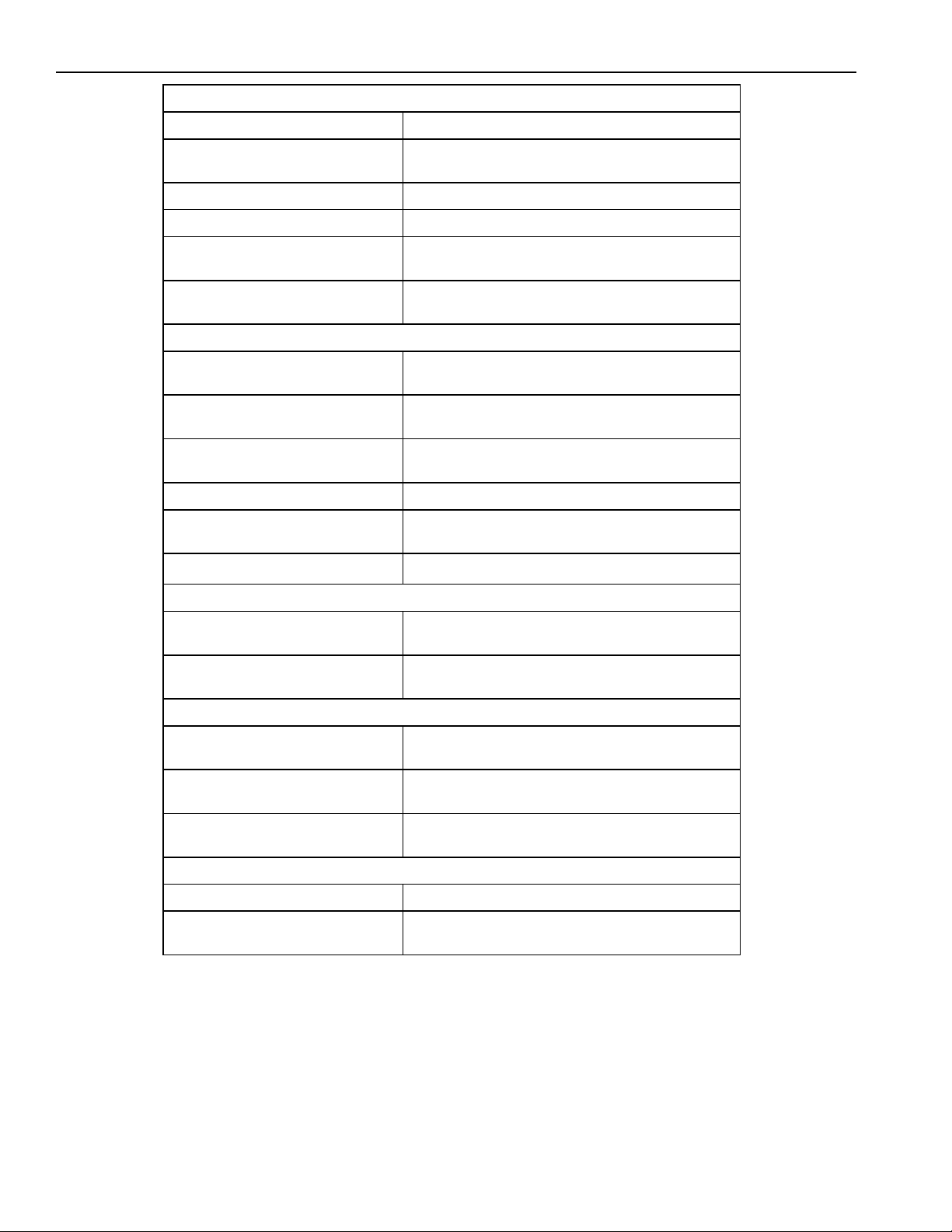
Ice Maker Troubleshooting Chart
3:00 Ejector Position
Contaminated Replace module
Jamm ed cubes
Notice size and density of cubes
Refrigerator or ice maker not level Level refrigerator or ice maker
No power to ice maker Determine discontinuity by tracing power
Excessive water-fill volume Adjust module screw, lower water pressure, or
Cubes falling back into mold during
ejection
Contaminated Replace mold and heater assembly
Thermostat out of calibration Replace therm ost at
Open heater circuit
Motor should oscillate
Little or no alumilastic on thermost at Apply alumilastic to thermostat
Heater not staked in mold Replac e mold and heater assembly
Broken locking tabs on vertical cam Replace module
Un-jam cubes
replace water valve
Replace fill cup
Check fill tube assemby
4:00 Ejector Position
Apply alumilastic
Apply alumilastic
Replace mold and heater assembly
Apply alumilastic
Apply alumilastic
6:00 Ejector Position
Contaminated Replace mold and heater assembly
Apply alumilastic
Insufficient water to ice maker,
small or hollow cubes
Contaminated
Motor will not oscillate
Shut-off arm stuck in ice or
obstructed
Cubes not formed properly Un-Jam
Contaminated Replace module
Cube frozen to fill cup or mold Un-jam
Refer to “Hollow Ice Cubes”
7:30 Ejector Position
Replace m odule
Remove obstruction
Replace m odule
Check fill cup and fill tube assembly
9:00 Ejector Position
Replace fill cup and module
RS1200001 48 November 1996
Page 49

Ice Maker Troubleshooting Chart
Excessive Ice Production
Problem Action
Shut-off arm not in actuator Replace shut-off arm in actuator
Deformed shut-off arm Replace shut-off arm
Broken shut-off lever or
lever bypassing vertical cam
Broken module actuator Replace module
Problem Action
Low water fill volume Adjust module screw, clear water path,
Improper freezer air-flow Direct air flow away from thermostat
Thermostat out of calibration Replace thermostat
Flooding or Ice in Bucket or Freezer
Problem Action
Thermostat out of calibration Replace thermostat
Jammed cube stalled in water-fill cycle Remove cube
Leaky water valve Replace water valve
Excessive water fill volume Replace water valve
Motor stalled in water-fill cycle
(12:00 ejector position)
Contaminated module Replace module
Refrigerator or ice maker not level Level refrigerator or ice maker
Excessive water pressure Decrease water pressure (20-120 psi) (1.4 - 8.2 bar)
Shorted and burned module shut-off
switch and contacts
Broken locking tab on verticle cam
(Stalled in water fill)
Fill-tube not pr operly positioned in
fill cup
Fill cup water opening blocked Replace fill cup
Replace module
Hollow Ice Cubes
or replace water valve
Apply alumilastic
Apply alumilastic
Determine reason for stall
Replace module
Replace module
Replace module
Reposition fill tube
Cubes fall over back of ice maker,
melting in freezer
Replace fill cup
November 1996 49 RS1200001
Page 50

Ice Maker Wiring Diagram and Parts Layout
115
RS1200001 50 November 1996
Page 51

B136CKR1 and B136CKL1 Custom Handle Kit
Introduction
Recognize this symbol as a safety
precaution.
WARNING
To avoid severe personal injury or property
damage from refrigerator tipping over, do not
open more than one door at a time, until
refrigerator has been secured to structure.
Caution
To avoid personal injury protect hands and
arms by wearing gloves. Trim pieces may
have sharp edges.
Caution
To avoid property damage, protect soft vinyl
or other flooring with cardboard, rugs, or other
protective material.
Read entire manual before installing kit. Align parts
checking for proper fit before beginning. All necessary
tools and materials must be available prior to
installation. Verify all listed parts are included in kit. If
parts are missing, contact source from whom kit was
purchased.
• Two people are recommended to install kit.
• Mechanical experience is required to install kit.
• If unable to solve a problem during installation,
contact an authorized Amana technician. Locate
a Factory Service Center or independent
authorized technician by calling 1-800-628-5782
inside U.S.A. and 1-319-622-5511 outside U.S.A.
Service is at owner’s expense.
This kit is designed for applications where custom
handles are desired to replace factory installed handles.
Kit includes trim necessary to hold custom panels in
place on refrigerator door and freezer drawer. Custom
handles are not provided and is the responsibility of the
consumer to provide.
Parts List
B136CKR1
Part Number Description Quantity
12063501 Extrusion freezer door frame 1
12063503 Extrusion door frame 1
12116501 Installation instructions 1
M0275148
12063703 Handle insert 1
B136CKL1
Part Number Description Quantity
12063501 Extrusion freezer door frame 1
12063503 Extrusion door frame 1
12116501 Installation Instructions 1
M0275148
12063703 Handle insert 1
1" Wide double back tape 30"
1" Wide double back tape 30
"
November 1996 51 RS1200001
Page 52

B136CKR1 and B136CKL1 Custom Handle Kit
Panel Dimensions
Refrigerator door without extruded handle
Freezer door without extruded handle
Refrigerator door with or without extruded handle
Freezer door with extruded handle
Refrigerator door with extruded handle
Freezer door with extruded handle
Freezer door without extruded handle
Panel
Depth
3/4" 35 1/4" 51 7/16"
3/4" 35 1/4" 23 1/16"
1/4" 35" 51 1/4"
1/4" 35" 23 11/32" 3 1/2" 1/2"
3/4" 32 1/4" 51 7/16"
3/4" 35 1/4" 20 9/16"
1/4" 35" 22 27/32"
A B C D
Door Panels with Hinge on Right Side and Extruded Handle
Reverse view for hinge on left side
Hinge
clearance
RS1200001 52 November 1996
Page 53

B136CKR1 and B136CKL1 Custom Handle Kit
Refrigerator, Freezer Door Panel with Custom Handle (inches)
Center align panel brackets on back of panel.
Panel brackets
3/4" Panel Mounted to 1/4" Filler Panel and Location of Panel Brackets for 3/4" Panel
Installations
1/4" filler
Door trim
Panel bracket
Front of decorator panel
3/4" raised
overlay panel
panel
November 1996 53 RS1200001
Page 54

B136CKR1 and B136CKL1 Custom Handle Kit
.250
3.780
Freezer Drawer Top Wood Spacer Right Side Hinge Cutout Dimensions For 3/4" Panels
3.780
35.250
(inches) (actual size)
Mount spacer to top of freezer drawer using 1" wide double sided foam tape.
2.892
Radius .888
.703
1.991
Freezer Drawer Right Side Hinge Top Wood Spacer Dimensions (1/2" thick) for 3/4"
Panels (inches)
Mount spacer to top of freezer drawer using 1" wide double sided foam tape.
2.892
Radius .888
2.563
.703
.250
RS1200001 54 November 1996
1.991
2.563
Page 55
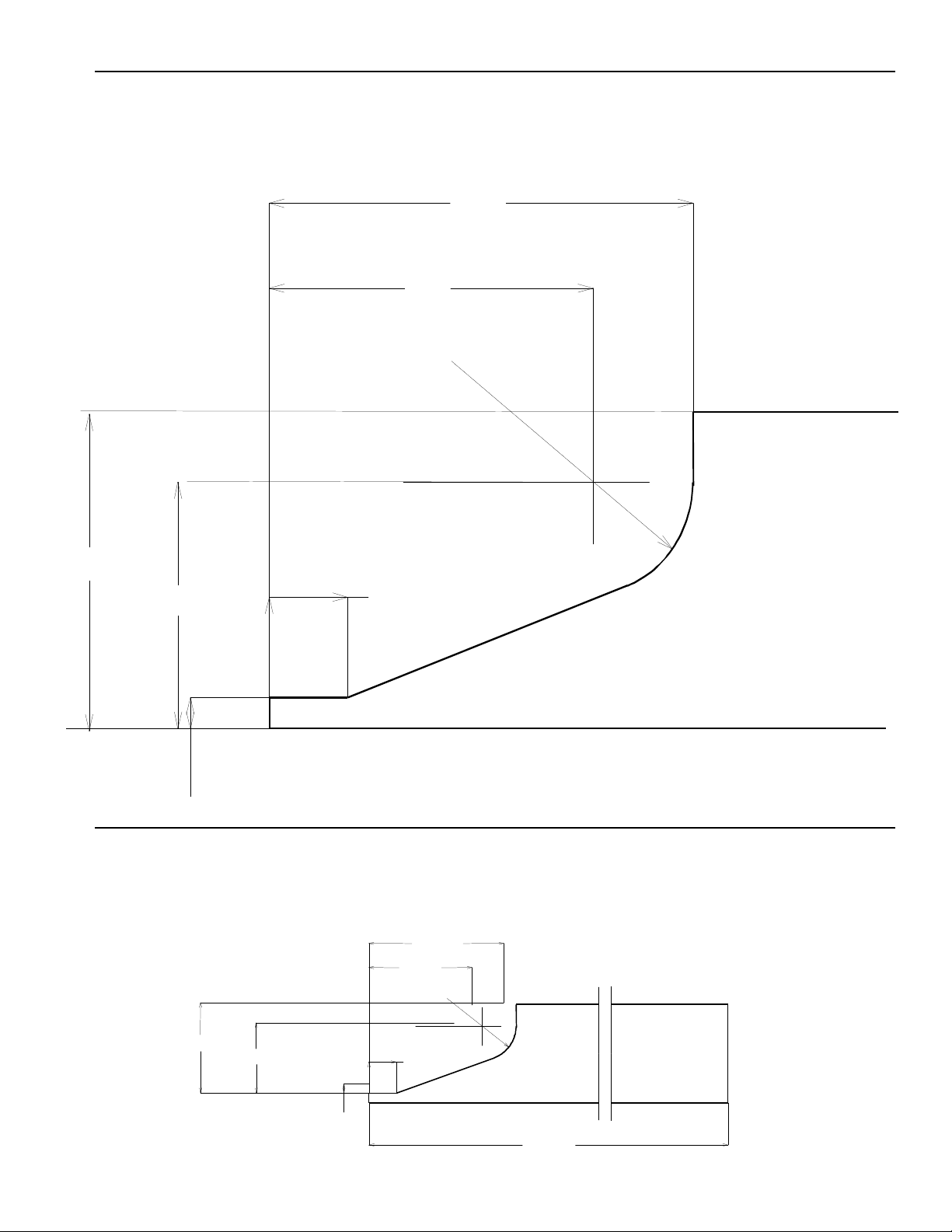
B136CKR1 and B136CKL1 Custom Handle Kit
.250
3.780
Freezer Drawer Top Wood Spacer Left Side Hinge Cutout Dimensions for 3/4" Panels
3.780
35.250
(inches) (actual size)
Mount spacer to top of freezer drawer using 1" wide double sided foam tape.
2.892
Radius .888
2.563
1.991
.703
Freezer Drawer Left Side Hinge Top Wood Spacer Dimensions (1/2" thick) for 3/4" Panels
(inches)
Mount spacer to top of freezer drawer using 1" wide double sided foam tape.
2.892
Radius .888
2.563
November 1996 55 RS1200001
1.991
.703
.250
Page 56

B136CKR1 and B136CKL1 Custom Handle Kit
Procedures
Refrigerator Door
1. Remove handle insert by prying off one end and
pulling handle insert away from door.
2. Remove nine 3/8" screws from refrigerator handle.
Remove handle from door.
Caution
To avoid property damage, maintain grip on
handle after screws have been removed.
Handle will be loose once screws have been
removed and may fall.
Handle
Insert
Refrigerator
handle
3/8"
screws
5. Drive low profile screws into panel with screwdriver.
• Panel brackets must be exactly flush to 1/16"
inboard of panel edge.
• For ease of panel installation, 2 people are
required to lift and guide panel into trim.
• Install 1 panel at a time.
6. Align panel in trim and push evenly. For smoother
installation, apply bar soap on door trim and
refrigerator trim. If panel binds loosen top door trim.
Adjust panel and retighten. See "3/4" Panel
Mounted to 1/4" Filler Panel and Location of Panel
Brackets for 3/4" Panel Installations", page 4.
7. Install new refrigerator door trim by replacing nine,
3/8" screws.
8. Replace handle insert. Start one edge of insert in
track and press other edge into track while working
up side of door.
Freezer Drawer
1. Remove freezer drawer handle insert by prying one
end out of track and pulling upward, away from
drawer.
2. Remove five, 1" screws from freezer drawer handle.
Lift freezer handle and handle/trim spacer off
freezer drawer.
3. Align panel brackets (supplied) with center edge of
panel see "Refrigerator, Freezer Door Panel with
Custom Handle" page 4 . Install brackets using 1/4"
screws.
• Brackets and screws are provided with
refrigerator, and not a part of this kit. Custom
panels are consumers responsibility.
• Panel should have handle already installed.
• Head of screws used to mount handles to panel
must not exceed .15" in height. Screw head
height higher than .15" will interfere when
installing panels. If screws head height is greater
than .15", countersink heads in back of panel.
4. If base panel is less than 1/4", use plastic shims.
Shims go between bracket and wood to space
panels to desired depth.
• Shims are provided with refrigerator, and are not
part of this kit.
1"
screws
Handle
insert
Handle/
Trim
spacer
3. Remove trim insert from one side trim piece by
prying one end out of track and pulling upward away
from the drawer.
4. Remove five 3/8" screws from side trim. Remove
side trim from freezer drawer.
Freezer
handle
RS1200001 56 November 1996
Page 57

B136CKR1 and B136CKL1 Custom Handle Kit
Trim
Top trim
Side trim
5. See "Procedures, Refrigerator Door", steps 3
through 5 for panel assembly procedure.
6. Align panel in trim and push evenly. Start at one end
and work across. For smoother installation, apply
bar soap on door trim and freezer trim.
7. Replace side trim by inserting five, 3/8" screws.
8. Replace trim insert. Start one edge of insert in track
and press other edge into track while working up
side of door.
9. Install new top trim by replacing five, 1" screws.
10. Cut new handle insert to a length of 35 1/4". Install
new trim insert. Start one edge of insert in track and
press other edge into track while working up side of
door.
11. Optional: install filler block on top of top trim using
1" wide double sided foam tape provided.
• For dimensions of filler block see "Freezer Drawer
Top Wood Spacer Right Side Hinge Cutout
Dimensions" pages 5, or "Freezer Drawer Top
Wood Spacer Left Side Hinge Cutout Dimensions"
page 6 of this manual.
• Double sided tape is provided in three, 10" strips.
• Verify placement of filler block before applying
double sided tape. Tape cannot be removed once
applied to filler block.
insert
3/8"
screws
November 1996 57 RS1200001
Page 58

B136SPK1 ¼" Facia Front Enclosure Kit
Introduction
Recognize this symbol as a safety
precaution.
WARNING
To avoid severe personal injury or property
damage from refrigerator tipping over, do not
open more than one door at a time, until
refrigerator has been secured to structure.
Caution
To avoid property damage, protect soft vinyl
or other flooring with cardboard, rugs, or other
protective material.
Caution
To avoid personal injury, wear gloves to
protect hands and arms. Trim pieces may
have sharp edges.
Parts List
Part Number Description Quantity
12115803 Right cabinet extrusion 1
12128401 Cabinet extrusion 2
12200901 Cabinet bracket 2
12098007 Decorator panel bracket 2
12098005 Decorator panel bracket 2
M0215318 Small screw 10
M0210417 Small screw 7
M0223729 Small screw 58
12118504 Left cabinet extrusion 1
12064304 Toe grille 1
12064404 Toe grille 1
12116503 Installation Instructions 1
12119604 Door bracket shim 8
12119605 Door bracket shim 4
12119602 Cabinet bracket shim 8
Read entire manual before installing kit. Align parts
checking for proper fit before beginning. All necessary
tools and materials must be available prior to
installation. Verify all listed parts are included in kit. If
parts are missing, contact source from whom kit was
purchased.
• Two people are recommended to install kit.
• Mechanical experience is required to install kit.
• If unable to solve a problem during installation,
contact an authorized Amana technician. Locate
a Factory Service Center or independent
authorized technician by calling 1-800-628-5782
inside U.S.A. and 1-319-622-5511 outside U.S.A.
Service is at owner’s expense.
This kit is designed for applications requiring a 1/4"
wood side panel be attached to one or both sides of the
refrigerators. Kit may also have a 3/4" wood panel
attached to the base panel to bring the side panel to full
refrigerator depth. Kit includes trim and parts needed to
attach panel to the side of refrigerator.
RS1200001 58 November 1996
Page 59

B136SPK1 ¼" Facia Front Enclosure Kit
Panel Dimensions
Side Panel Dimensions
Panel Thickness Minimum Height Minimum Depth
¼" Side Panels
¾" Side Panels
Panel height will vary depending how high leveling wheels have been raised when leveling
refrigerator, and cabinet height.
If cabinet depth is greater than 24", adjust panel accordingly.
Optional 3/4" panel may be added to cover side extrusion as shown below, and on page 4.
83.125 21.750
83.125 23.982
3/4" Panel
minimum
depth
1/4" Panel
minimum
depth
Minimum
height
November 1996 59 RS1200001
Page 60

B136SPK1 ¼" Facia Front Enclosure Kit
Location of Panel Brackets on Side Panels
If cabinet depth is greater than 24", adjust panel size accordingly.
Left
side
.828
.993
Top view Right
L-Bracket
1/4" Panel
Z-Bracket
1/4" Panel
Refrigerator door
side
.186
21.750
1/4" Minimum
panel depth
.993
23.982
3/4"Minimum
panel depth
Side
panel
Refrigerator door panel
2.500
Front
panel
bracket
Side View
Bottom
panel
bracket
L-Bracket
11.281
2.062
1.50
RS1200001 60 November 1996
Page 61

B136SPK1 ¼" Facia Front Enclosure Kit
Full Side View of Front Panel Bracket, Bottom Panel Bracket, and L-Bracket Location
Front panel
bracket
Bottom
panel
bracket
L-Bracket
November 1996 61 RS1200001
Page 62

B136SPK1 ¼" Facia Front Enclosure Kit
Procedures
1. Remove toe grille from front of refrigerator by
removing 2 screws and pulling forward.
Clip
2. Remove drain pan clip from old toe grille and snap
onto toe grille provided. Install toe grille by
attaching to cabinet in same holes as previous toe
grille, with 2 truss head 1/4" sheet metal screws.
• New toe grille will not be as wide as original toe
grille to allow installation of new side extrusion.
3. Remove front side extrusion and white spacer strip
by removing 11 screws on both left and right sides.
Retain white spacer strip located on machine
compartment side.
4. Install new front side extrusion provided with kit
using screws removed in step 3. Replace white
spacer strip along machine compartment side.
• If cabinet opening is less then 84 1/4" high, side
extrusion needs to be trimmed to desired height.
Front
side extrusion
Side
extrusion
Side of
refrigerator
5. Mount left and right panel brackets to wood panel
using 3/16" phillips screws provided.
• If base panel is not 1/4" thick use plastic shims
provided with kit to bring base panel depth up to
1/4".
3/4" Raised
overlay panel
(Optional)
1/4" Filler
panel
Panel
bracket
RS1200001 62 November 1996
Page 63

B136SPK1 ¼" Facia Front Enclosure Kit
6. Mount bottom panel brackets using five, 3/16"
phillips screws.
• If base panel is not 1/4" thick, use plastic shims
provided with kit to bring base panel depth up to
1/4".
7. Mount bottom cabinet extrusion using five, 1/4" flat
head phillips screws.
9. Slide panels into place on left and right side of
refrigerator. Verify that panel bracket is resting in
track on bottom cabinet extrusion. For smoother
installation, apply bar soap to cabinet extrusions
and panel brackets.
Bottom cabinet
extrusion
8. While facing back of refrigerator, remove 7 screws
from right edge of refrigerator cabinet.
Bottom cabinet
extrusion
Side of
refrigerator
• Also, front panel bracket must fit in gap in front
side extrusion.
Slide
panel in
here
1/4" Panel
3/4" Panel
(Optional)
L-Bracket
Panel
bracket
Remove
screws
10. Line up holes in right side L-bracket with holes from
November 1996 63 RS1200001
Bottom cabinet
extrusion
7 screws removed in step 4. Attach L-bracket to
back of refrigerator using 7 screws removed in
step 4.
Page 64

B136SPK1 ¼" Facia Front Enclosure Kit
11. Line up holes in left side L-bracket with holes in left
side edge of refrigerator back. Attach left side
L-bracket to back of refrigerator using 7 truss head
1/4" sheet metal screws.
Left
L-Bracket
Right
L-Bracket
RS1200001 64 November 1996
Page 65

B136SPK2 ¾" Side Panel Kit
Part Number
Description
Quantity
12098007
Decorator panel bracket
2
12119605
Door bracket shim
4
Introduction
Recognize this symbol as a safety
precaution.
WARNING
To avoid severe personal injury or property
damage from refrigerator tipping over, do not
open more than one door at a time, until
refrigerator has been secured to structure.
Caution
To avoid property damage, protect soft vinyl
or other flooring with cardboard, rugs, or other
protective material.
Caution
To avoid personal injury, wear gloves to
protect hands and arms. Trim pieces may
have sharp edges.
Read entire manual before installing kit. Align parts
checking for proper fit before beginning. All necessary
tools and materials must be available prior to
installation. Verify all listed parts are included in kit. If
parts are missing, contact source from whom kit was
purchased.
• Two people are recommended to install kit.
• Mechanical experience is required to install kit.
• If unable to solve a problem during installation,
contact an authorized Amana technician. Locate
a Factory Service Center or independent
authorized technician by calling 1-800-628-5782
inside U.S.A. and 1-319-622-5511 outside U.S.A.
Service is at owner’s expense.
Parts List
12128401 Bottom cabinet extrusion 2
12200901 Cabinet bracket 2
12098005 Decorator panel bracket 2
M0215318 Small screw 10
M0210417 Small screw 7
M0223729 Small screw 58
12116504 Installation Instructions 1
12119604 Door bracket shim 8
12119602 Cabinet bracket shim 8
This kit is designed for applications with one or both
sides of refrigerator being exposed. Kit includes trim
neccesary to install 3/4", or 1/4" wood panels on side of
refrigerator to coordinate with kitchen decor.
November 1996 65 RS1200001
Page 66

B136SPK2 ¾" Side Panel Kit
Panel height will vary depending how high leveling wheels have been raised when leveling
Panel Dimensions
Side Panel Dimensions
Panel Thickness (Inches) Minimum Height (Inches) Minimum Depth (Inches)
A B C*
¾" Panels
•
refrigerator, and cabinet height.
•
If cabinet depth is greater than 24", adjust panel size accordingly.
•
3/4" panels may be extended to cover door gasket, door side, or door panel as shown by
dimensions below and on page 4.
•
Add refrigerator door panel depth to dimension C if attempting to extend side panel to cover side of
front panel.
83.125 21.875 22.571 24.108
Panel Depth
*
C
B
A
Minimum
Height
RS1200001 66 November 1996
Page 67

B136SPK2 ¾" Side Panel Kit
Location of Panel Brackets on Side Panels
Left Side
.828
L-Bracket
3/4" Panel
Panel Bracket
Top View
Right Side
.186
Minimum
Depth A
Minimum
Depth B
Minimum
Depth C
1.118
.125
3/4" Panel
Refrigerator
Door
Refrigerator
Door Panel
Side view
1.118
C*
11.281
2.500
Front
Panel
Bracket
Bottom
Panel
Bracket
L-Bracket
2.062
1.50
November 1996 67 RS1200001
Page 68

B136SPK2 ¾" Side Panel Kit
Full Side View of Front Panel Bracket, Bottom Panel Bracket, and L-Bracket Location
Front
Panel
Bracket
Bottom
Panel
Bracket
L-Bracket
RS1200001 68 November 1996
Page 69

B136SPK2 ¾" Side Panel Kit
Procedure
1. Mount left and right panel brackets to wood panel
using 3/16" phillips screws provided.
• If base panel is not 1/4" thick, use plastic shims
provided with kit to bring base panel depth up to
1/4".
1/4" filler
3/4" raised
overlay panel
panel
Panel
bracket
4. While facing back of refrigerator, remove 7 screws
from right edge of refrigerator cabinet.
Remove
screws
2. Mount bottom panel brackets using 5, 3/16" phillips
screws.
• If base panel is not 1/4" thick use plastic shims
provided with kit to bring base panel depth up to
1/4".
3. Mount bottom cabinet extrusion using 5, 1/4" flat
head phillips screws.
Bottom cabinet
extrusion
5. Slide panels into place on left and right side of
refrigerator. Verify that panel bracket is resting in
track on bottom cabinet extrusion. For smoother
installation, apply bar soap to cabinet extrusions
and panel brackets.
Bottom cabinet
extrusion
Side of
refrigerator
Panel
Panel
bracket
November 1996 69 RS1200001
Page 70

B136SPK2 ¾" Side Panel Kit
• Front panel bracket must fit in gap in front side
extrusion.
L-bracket
Slide
panel in
here
Bottom cabinet
extrusion
6. Line up holes in right side L-bracket with holes from
7 screws removed in step 4. Attach L-bracket to
back of refrigerator using screws removed in step
4.
7. Line up holes in left side L-bracket with holes in left
side edge of refrigerator back. Attach left side
L-bracket to back of refrigerator using 7 truss head
1/4" sheet metal screws provided in kit.
Left
L-bracket
Right
L-bracket
RS1200001 70 November 1996
 Loading...