

Amana DEC14E, DEC18E, DEC11E, DEC14E2, DEC18E2 Training Manual
...
Training Manual
.6 − 50 Hz Compact Models
HDC−5 _ 50 Hz R2
MENUMASTER
C O M M E R C I A L M I C R O W A V E O V E N
R
June 2007
www.amanacommercial.com
1

Model Number List
DEC11E..........(P1325203M)
(P1330512M)
DEC11E2........(P1331213M)
(P1331235M)
DEC14E..........(P1325207M)
(P1330516M)
DEC14E2........(P1331217M)
(P1331239M)
DEC18E..........(P1325211M)
(P1330520M)
DEC18E2........(P1331221M)
(P1331243M)
HDC511..........(P1325201M)
(P1330510M)
HDC511A .......(P1325213M)
HDC5112........(P1331211M)
MCHDC521 ....(P1331246M)
(P1331225M)
UC11E............(P1325204M)
(P1330513M)
UC11E2..........(P1331214M)
(P1331236M)
UC14E............(P1325208M)
(P1330517M)
UC14E2..........(P1331214M)
(P1331240M)
UC18E............(P1325212M)
(P1330517M)
UC18E2..........(P1331222M)
(P1331244M)
UHDC511 .......(P1325202M)
(P1330511M)
(P1331233M)
HDC514..........(P1325205M)
(P1330514M)
HDC514A .......(P1325214M)
HDC5142........(P1331215M)
(P1331237M)
HDC518..........(P1325209M)
(P1330518M)
HDC518A .......(P1325215M)
HDC5182........(P1331219M)
(P1331241M)
HDC5212........(P1331224M)
(P1331245M)
UHDC5112 .....(P1331212M)
(P1331234M)
UHDC514 .......(P1325206M)
(P1330515M)
UHDC5142 .....(P1331216M)
(P1331238M)
UHDC518 .......(P1325210M)
(P1330519M)
UHDC5182 .....(P1331220M)
(P1331242M)
CDEC14E2.....(P1331251M)
CDEC18E2 (P1331252M)
CDEC21E2.....(P1331253M)
CHDC5142 (P1331248M)
CHDC5182 (P1331249M)
CHDC5212 (P1331250M)
2

Table of Contents
Model Number List...............................................................................................................2
Table of Contents.................................................................................................................3
Specifications.......................................................................................................................4
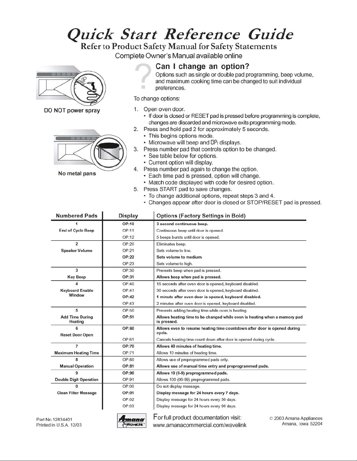
Quick Start Reference Guide...............................................................................................5
Inner Door/Window Removal...............................................................................................7
Technical Bulletin CR-236-B - Broken Tray........................................................................8
Air Flow.................................................................................................................................9
Improved Filter for .6 Compact Ovens..............................................................................10
Interlock Switches..............................................................................................................11
Switch Replacement / Door Adjustment...........................................................................12
Touch Panel and Control Board........................................................................................13
Disassembly ............................................................................................................... 14 – 16
Component Specifications........................................................................................ 17 – 19
Power Testing Procedure.................................................................................................. 20
Isolation Test – Two Magnetron Models...........................................................................21
Wiring and Schematic Diagrams................................................................................22 - 25
3
CAUTION
!
All safety information must be followed as provided in Service Manual RS5320013.
!
WARNING
To avoid risk of electrical shock, personal injury or death; disconnect power to oven and discharge capacitor before servicing, unless testing requires power.
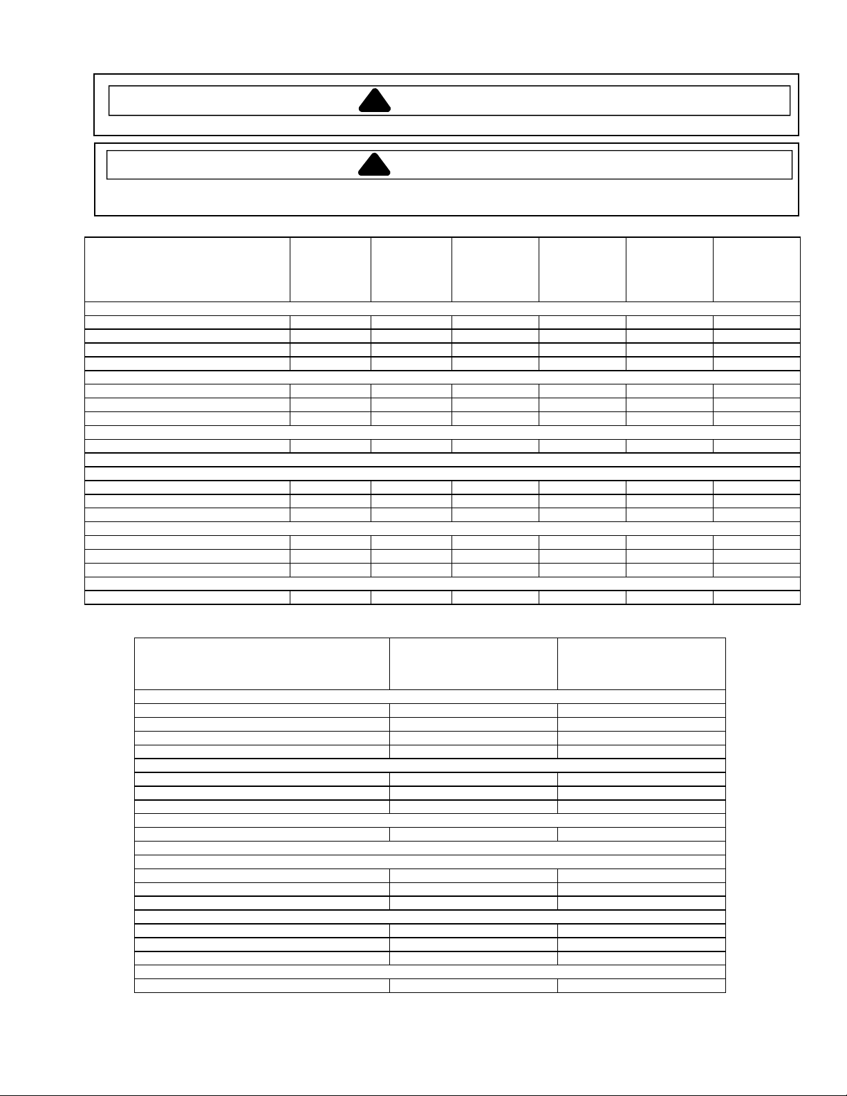
Models
UHDC511*
UC11E*
Power Source
Voltage AC 230 VAC 230 VAC 230 VAC 230 VAC 230 VAC 230 VAC
Amperage (single unit) 13 A 13 A 13 A 13 A 13 A 13 A
Frequency 50 Hz 50 Hz 50 Hz 50 Hz 50 Hz 50 Hz
Single phase, 3 wire earthed X X X X X X
Power Output
Nominal microwave energy (IEC705) 1100 Watts 1100 Watts 1400 Watts 1400 Watts 1800 Watts 1800 Watts
Minimum temperature rise (∆T) 11º F / 5.5º C 11º F / 5.5º C 14º F / 7.5º C 14º F / 7.5º C 18º F / 10º C 18º F / 10º C
Operating frequency 2450 MHz 2450 MHz 2450 MHz 2450 MHz 2450 MHz 2450 MHz
Power Consumption
Cook condition microwave 1800 W / 8 A 1800 W / 8 A 2300 W / 10 A 2300 W / 10 A 3000 W / 13 A 3000 W / 13 A
Dimensions
Cabinet
Width 423 mm 423 mm 423 mm 423 mm 423 mm 423 mm
Height 335 mm 335 mm 335 mm 335 mm 335 mm 335 mm
Depth 548 mm 548 mm 578 mm 578 mm 578 mm 578 mm
Oven Interior
Width 331 mm 331 mm 331 mm 331 mm 331 mm 331 mm
Height 175 mm 175 mm 175 mm 175 mm 175 mm 175 mm
Depth 305 mm 305 mm 305 mm 305 mm 305 mm 305 mm
Weight
Crated 29 kg 29 kg 31 kg 31 kg 31 kg 31 kg
HDC511*
HDC511A
DEC11E*
UHDC514*
UC14E*
HDC514*
HDC514A
DEC14E*
CHDC514
CDEC14E2
UHDC518*
UC18E*
HDC518*
HDC518A
DEC18E*
CHDC518
CDEC18E2
DEC21E2
Models MCHDC521
Power Source
Voltage AC 230 VAC 230 VAC
Amperage (single unit) 16 A 32 A
Frequency 50 Hz 50 Hz
Single phase, 3 wire earthed X X
Power Output
Nominal microwave energy (IEC705) 2100 Watts 2100 Watts
Minimum temperature rise (∆T) 21º F / 11.5º C 21º F / 11.5º C
Operating frequency 2450 MHz 2450 MHz
Power Consumption
Cook condition microwave 3100 Watts / 13.5 A 3100 Watts / 13.5 A
Dimensions
Cabinet
Width 423 mm 423 mm
Height 335 mm 335 mm
Depth 578 mm 578 mm
Oven Interior
Width 331 mm 331 mm
Height 175 mm 175 mm
Depth 305 mm 305 mm
Weight
Crated 31 kg 31 kg
HDC5212
CHDC5212
CDEC21E2
4

5
6
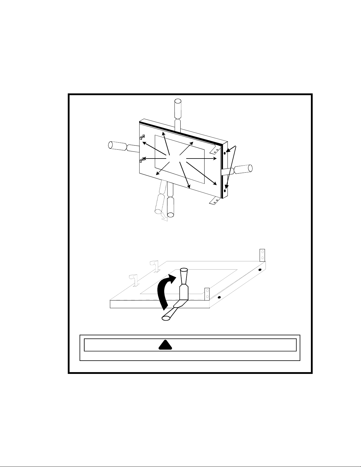
Inner Door/Window Removal
1. Open oven door.
2. Remove screws on hinge side.
3. Beginning at the bottom, carefully insert 1” putty knife between inner and outer door. Pry up on inner
door to release tabs, (2 tabs per side). Work in a clockwise direction to release all tabs, see illustration
below.
3
2
Remove
screws
Tabs
4
1
CAUTION
!
When glass retainer is removed, be careful glass does not fall out of frame.
7
Bulletin
√ Comm. Microwave Dehumidifier Dishwasher
Domm. Microwave √ Export Comm. Heating Product
Laundry Product PTAC Products Range Product
Refrigerator/Fzr Room Air Cond.
Type Parts Manual Update
Policy Letter
√ Service Information
Attention Service Managers
√ Service and Parts Managers
Models CRC and HDC Compact Commercial Ovens
Issue Broken tray as a result of arcing at front lip of cavity.
Warranty Ceramic trays may be claimed under warranty only if damage was caused by
antenna failure (arcing).
Trays are not covered under warranty if there is evidence that damage was caused by impact,
thermal shock (frozen or refrigerated product placed on warm tray), oven operated with metal pans,
oven operated without a food load or lack of proper cleaning and maintenance.
NOTE: Typical symptoms of metal pan usage or empty cavity operation include arc spots on the
front lip of cavity, 1 to 2 inches from either side.
Date July 31, 2001
No CR−236−B
EXCMW-125-B
Page 1 of 1
Action If encountering arcing at front lip of cavity, proceed as follows:
1. Check antenna operation – if either antenna is stalled, hot spots will occur.
2. Remove oven tray.
3. Thoroughly remove any carbon build-up from front lip using fine grade sandpaper.
4. Thoroughly clean cavity and front lip removing all old RTV.
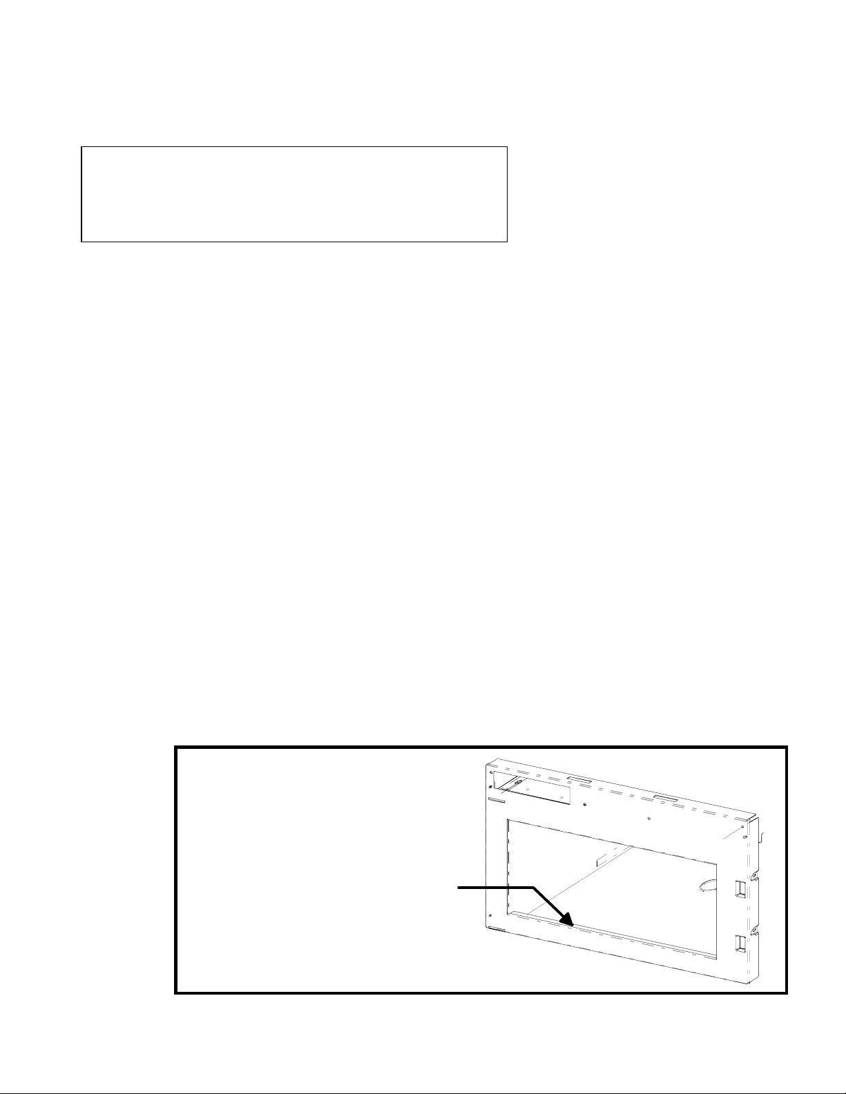
5. Before installing new tray, apply a generous bead of RTV on the front lip of cavity, (see below).
6. Install new tray and reseal using instructions supplied with the tray.
7. If arcing has damaged the oven door, replace inner oven door and inspect door ring weldment
for arcing.*
8. Replace door ring weldment if it is damaged.*
*To ensure proper operation, use the instructions in the Service Manual when reinstalling the
oven door.
Apply a generous bead
of RTV along this lip
before installing oven tray
8
 Loading...