

Page 1

Service
This manual is to be used by qualified appliance
technicians only. Maytag does not assume any
responsibility for property damage or personal
injury for improper service procedures done by
an unqualified person.
International
Bottom Mount
Refrigerators
This Base Manual covers general information
Refer to individual Technical Sheet
for information on specific models
This manual includes, but is
not limited to the following:
Amana
AB1924PEK*
AB2026PEK*
AB2225PEK*
AB2226PEK*
AB2526PEK*
G32026PEK*
G32526PEK*
GB1924PEK*
GB2225PEK*
GB2526PEK*
16023324
July 2004
Page 2
!
!
!
!
Important Information
Important Notices for Servicers and Consumers
Maytag will not be responsible for personal injury or property damage from improper service procedures. Pride and
workmanship go into every product to provide our customers with quality products. It is possible, however, that
during its lifetime a product may require service. Products should be serviced only by a qualified service technician
who is familiar with the safety procedures required in the repair and who is equipped with the proper tools, parts,
testing instruments and the appropriate service information. IT IS THE TECHNICIANS RESPONSIBILITY TO
REVIEW ALL APPROPRIATE SERVICE INFORMATION BEFORE BEGINNING REPAIRS.
WARNING
To avoid risk of severe personal injury or death, disconnect power before working/servicing on appliance to avoid
electrical shock.
To locate an authorized servicer, please consult your telephone book or the dealer from whom you purchased this
product. For further assistance, please contact:
Customer Service Support Center
CAIR Center
Web Site Telephone Number
WWW.AMANA.COM ............................................... 1-800-843-0304
WWW.JENNAIR.COM ............................................ 1-800-536-6247
WWW.MAYTAG.COM ............................................. 1-800-688-9900
CAIR Center in Canada .......................................... 1-800-688-2002
Amana Canada Product .......................................... 1-866-587-2002
Recognize Safety Symbols, Words, and Labels
DANGER
DANGER—Immediate hazards which WILL result in severe personal injury or death.
WARNING
WARNING—Hazards or unsafe practices which COULD result in severe personal injury or death.
CAUTION
CAUTION—Hazards or unsafe practices which COULD result in minor personal injury, product or property
damage.
2 16023324 Rev. 0 ©2004 Maytag Services
Page 3

Table of Contents
Important Information .................................................... 2
Product Design ............................................................. 4
Component Testing ....................................................... 5
Service Procedures ......................................................10
Service Equipment .......................................................10
Drier Replacement ....................................................... 10
Refrigerant Precautions ................................................ 11
Line Piercing Valves ..................................................... 11
Open Lines .................................................................. 11
Compressor Operational Test ....................................... 11
Dehydrating Sealed Refrigeration System .................... 12
Leak Testing .................................................................12
Testing Systems Containing a
Refrigerant Charge ................................................. 12
Testing Systems Containing
No Refrigerant Charge ............................................12
Restrictions .................................................................. 13
Symptoms .............................................................13
Testing for Restrictions .......................................... 13
Evacuation and Charging .............................................. 14
Evacuation .............................................................14
Charging ................................................................ 15
Refrigerant Charge ................................................. 15
HFC134a Service Information ....................................... 16
Health, Safety, and Handling ..................................16
Comparison of CFC12 and HFC134a Properties .....16
Replacement Service Compressor ................................17
Compressor Testing Procedures ............................ 17
Brazing ........................................................................ 17
Refrigerant Flow ...........................................................18
Cabinet Air Flow ...........................................................19
Two Way Machine Compartment Air Flow Diagram ...... 20
One Way Machine Compartment
Air Flow Diagram .........................................................21
Typical External Sweat Pattern...................................22
Troubleshooting Chart................................................23
System Diagnosis ........................................................26
Disassembly Procedures
Fresh Food Door ....................................................29
Freezer Door ..........................................................29
Freezer Drawer ......................................................29
Refrigerator Compartment
Light Bulb ..............................................................29
Light Bulb Assembly .............................................. 29
Light Bulb Sockets ................................................ 30
PC Control Board ...................................................30
Light Switch ...........................................................30
Temp- Assure™ Damper control ............................30
Fresh Food Thermistor ...........................................30
Water Tank ............................................................30
Water Dispenser ....................................................31
Freezer Compartment
Freezer Thermistor ................................................. 31
Light Socket .......................................................... 31
Light Switch ...........................................................31
Freezer Back Panel ............................................... 31
Evaporator Fan and Evaporator Motor ................... 31
Defrost Terminator (thermostat) ..............................32
Defrost Heater ....................................................... 32
Evaporator Removal ...............................................32
Drawer Assembly ................................................... 33
Drawer Rails ..........................................................33
Rack and Pinion Gear ............................................ 33
Bottom of Cabinet
Front roller assembly ............................................. 33
Rear roller assembly............................................33
Machine Compartment
Condenser Fan and Fan motor ............................... 33
Compressor ........................................................... 33
Overload/Relay/Capacitor ....................................... 34
Condensate Drain Pan ........................................... 34
Condensate Drain Tube ..........................................34
Condenser Removal ............................................... 34
Control Board ( Mid Level)
Programming Mode ............................................... 35
Defrost Operation ...................................................35
Forced Defrost Mode ............................................. 35
Service Test Mode .................................................36
Service Test 1-Defrost Thermostat & Defrost Circuit
Test ....................................................................... 37
Service Test 2-Compressor/Condenser Fan Test ....37
Service Test 3-Evaporator/Freezer Fan Test ........... 37
Service Test 4-Fresh Food Thermistor Test ............ 38
Service Test 5-Freezer Thermistor Test .................. 38
Service Test 6-Open Damper Test ..........................39
Service Test 7-FF Performance Adjustment ............ 39
Service Test 8-FZ Performance Adjustment ............39
©2004 Maytag Services 16023324 Rev. 0 3
Page 4
Product Design
!
WARNING
To avoid risk of electrical shock, personal injury, or death, disconnect electrical power source to unit, unless test
procedures require power to be connected. Discharge capacitor through a resistor before attempting to service.
Ensure all earthing wires are connected before certifying unit as repaired and/or operational.
Refrigeration System
Compressor forces high temperature vapor into fan
cooled tube and wire condenser where vapor is cooled
and condensed into high pressure liquid by circulation
of air across condenser coil. (See Refrigerant Flow
Diagram, page 18)
High pressure liquid passes into post-condenser loop
which helps to prevent condensation around freezer
compartment opening and through molecular sieve drier
and into capillary tube. Small inside diameter of
capillary offers resistance, decreasing pressure, and
temperature of liquid discharged into evaporator.
Capillary diameter and length is carefully sized for each
system.
Capillary enters evaporator at top front. Combined liquid
and saturated gas flows through front to bottom of coil
and into suction line. Aluminum tube evaporator coil is
located in freezer compartment where circulating
evaporator fan moves air through coil and into fresh food
compartment.
Large surface of evaporator allows heat to be absorbed
from both fresh food and freezer compartments by
airflow over evaporator coil causing some of the liquid to
evaporate. Temperature of evaporator tubing near end of
running cycle may vary from -25°C to -32°C.
Saturated gas is drawn off through suction line where
superheated gas enters compressor. To raise
temperature of gas, suction line is placed in heat
exchange with capillary.
Defrost System
Mid Level Electronic Defrost
The Control Board adapts the compressor run time
between defrosts to achieve optimum defrost intervals
by monitoring the length of time the defrost heater is
on.
After initial power up, defrost interval is 4 hours
compressor run time. Defrost occurs immediately after
the 4 hours.
Note: Once unit is ready to defrost there is a 4 minute
wait time prior to the beginning of the defrost
cycle.
Optimum defrost is 15 minutes. Each additional minute
the defrost thermostat remains closed, 1 hr. is
subtracted from the previous defrost interval. Each
minute the thermostat opens prior to optimum defrost,
it extends the next defrost interval 1 hr. When defrost
thermostat opens there is a 4-6 minute drip time before
compressor restarts or Control Board will terminate
defrost at 25 minutes if defrost thermostat has not
opened and will reset the defrost interval to the 8 hr.
minimum setting.
4 hours of continuous compressor run resets the next
defrost interval to 8 hours and will initiate a defrost, if 8
hours of compressor run time has also occurred.
Temperature Controls
Freezer compartment temperature is regulated by air
sensing thermostat at top front of freezer compartment
which actuates compressor. Control should be set to
maintain freezer temperature between -17.8°C to -
18.9°C.
Fresh food compartment temperature is regulated by an
air damper control governing amount of refrigerated air
entering fresh food compartment from freezer. Fresh
food compartment temperature should be between
3.3°C and 4.4°C.
4 16023324 Rev. 0 ©2004 Maytag Services
Page 5
Component Testing
!
WARNING
To avoid risk of electrical shock, personal injury, or death, disconnect electrical power source to unit, unless test
procedures require power to be connected. Discharge capacitor through a resistor before attempting to service.
Ensure all earthing wires are connected before certifying unit as repaired and/or operational.
Component Description Test Procedures
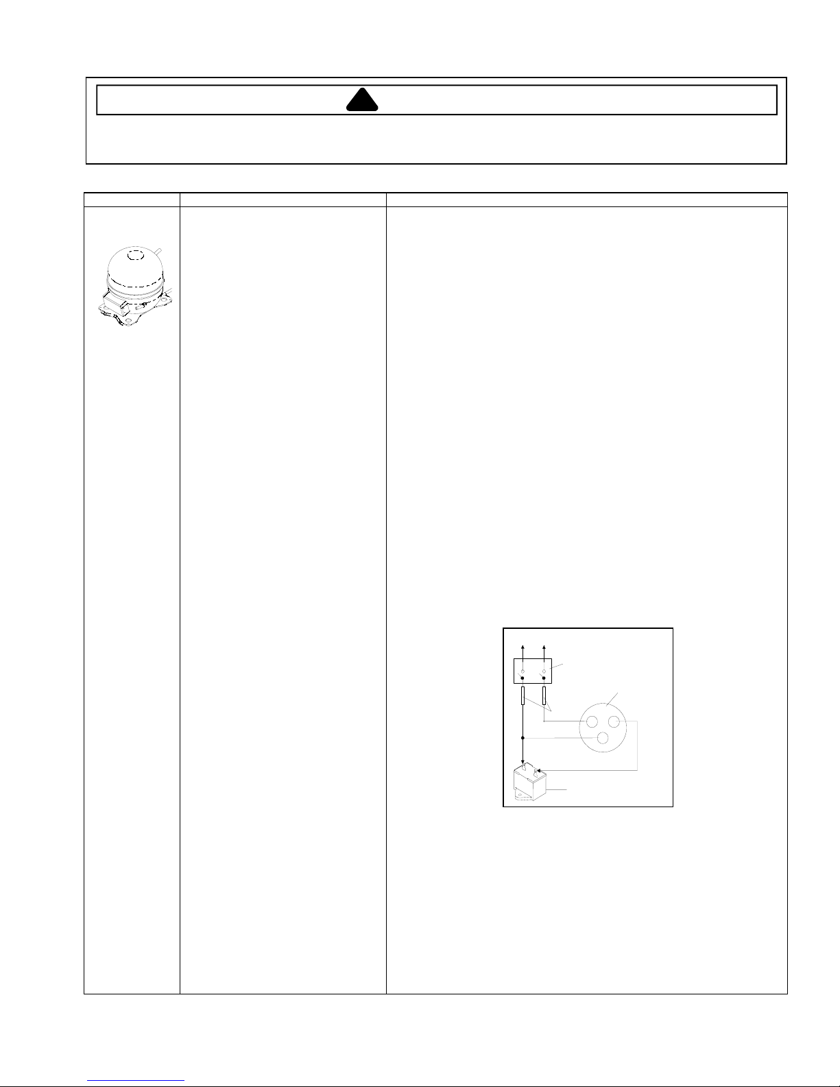
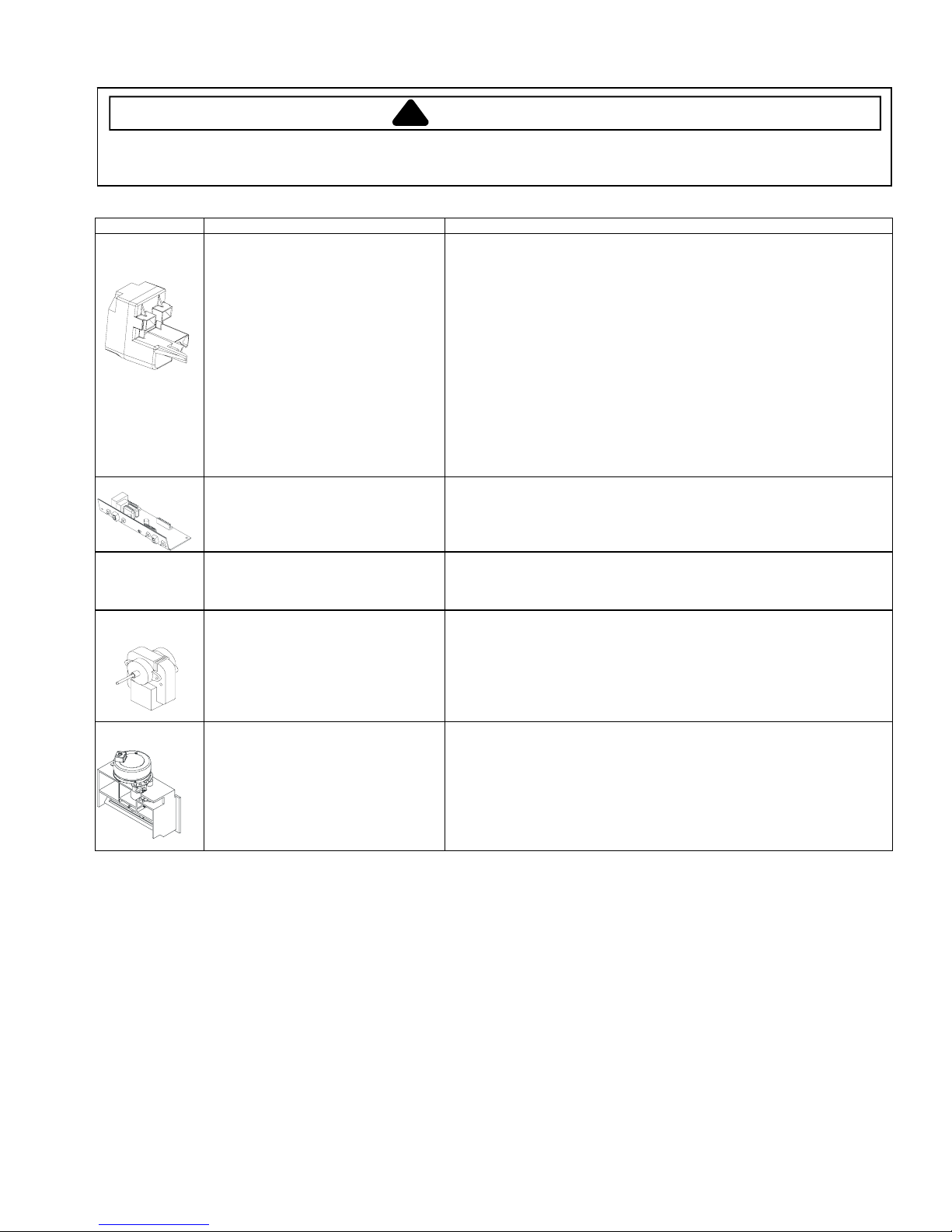
Compressor
When compressor electrical circuit is
energized, the start winding current
causes relay to heat. After an amount of
starting time, the start winding circuit
turns off. The relay will switch off the start
winding circuit even though compressor
has not started (for example, when
attempting to restart after momentary
power interruption).
With “open” relay, compressor will not
start because there is little or no current
to start windings. Overload protection will
open due to high locked rotor run winding
current.
With “shorted” relay or capacitor,
compressor will start and overload
protector will quickly open due to high
current of combined run and start
windings.
With open or weak capacitor, compressor
will start and run as normal but will
consume more energy.
Resistance test
1. Disconnect power to unit.
2. Discharge capacitor by shorting across terminals with a resistor for 1 minute.
NOTE: (Some compressors do not have a run capacitor.)
3. Remove leads from compressor terminals.
4. Set ohmmeter to lowest scale.
5. Check for resistance between
Terminals “S” and “C”, start winding
Terminals “R” and “C”, run winding
If either compressor winding reads open (infinite or very high resistance) or
dead short (0 ohms), replace compressor.
Ground test
1. Disconnect power to refrigerator.
2. Discharge capacitor, if present, by shorting terminals through a resistor.
3. Remove compressor leads and use an ohmmeter set on highest scale.
4. Touch one lead to compressor body (clean point of contact) and other probe
to each compressor terminal.
• If reading is obtained, compressor is grounded and must be replaced.
Operation test
If voltage, capacitor, overload, and motor winding tests do not show cause for
failure, perform the following test:
1. Disconnect power to refrigerator.
2. Discharge capacitor by shorting capacitor terminals through a resistor.
3. Remove leads from compressor terminals.
4. Wire a test cord to power switch.
5. Place time delayed fuse with UL rating equal to amp rating of motor in test
cord socket. (Refer to Technical Data Sheet)
6. Remove overload and relay.
7. Connect start, common and run leads of test cord on appropriate terminals of
compressor.
8. Attach capacitor leads of test cord together. If capacitor is used, attach
capacitor lead to a known good capacitor of same capacity.
To AC supply
©2004 Maytag Services
Switch
Compressor
Fuses
CRS
Capacitor
Test configuration
9. Plug test cord into multimeter to determine start and run wattage and to check
for low voltage, which can also be a source of trouble indications.
10. With power to multimeter, press start cord switch and release.
• If compressor motor starts and draws normal wattage, compressor is okay
and trouble is in capacitor, relay/overload, freezer temperature control, or
elsewhere in system.
• If compressor does not start when direct wired, recover refrigerant at high
side. After refrigerant is recovered, repeat compressor direct wire test. If
compressor runs after recovery but would not run when direct wired before
recover, a restriction in sealed system is indicated.
• If compressor does not run when wired direct after recovery, replace faulty
compressor.
16023324 Rev. 0 5
Page 6
Component Testing
!
WARNING
To avoid risk of electrical shock, personal injury, or death, disconnect electrical power source to unit, unless test
procedures require power to be connected. Discharge capacitor through a resistor before attempting to service.
Ensure all earthing wires are connected before certifying unit as repaired and/or operational.
Component Description Test Procedures
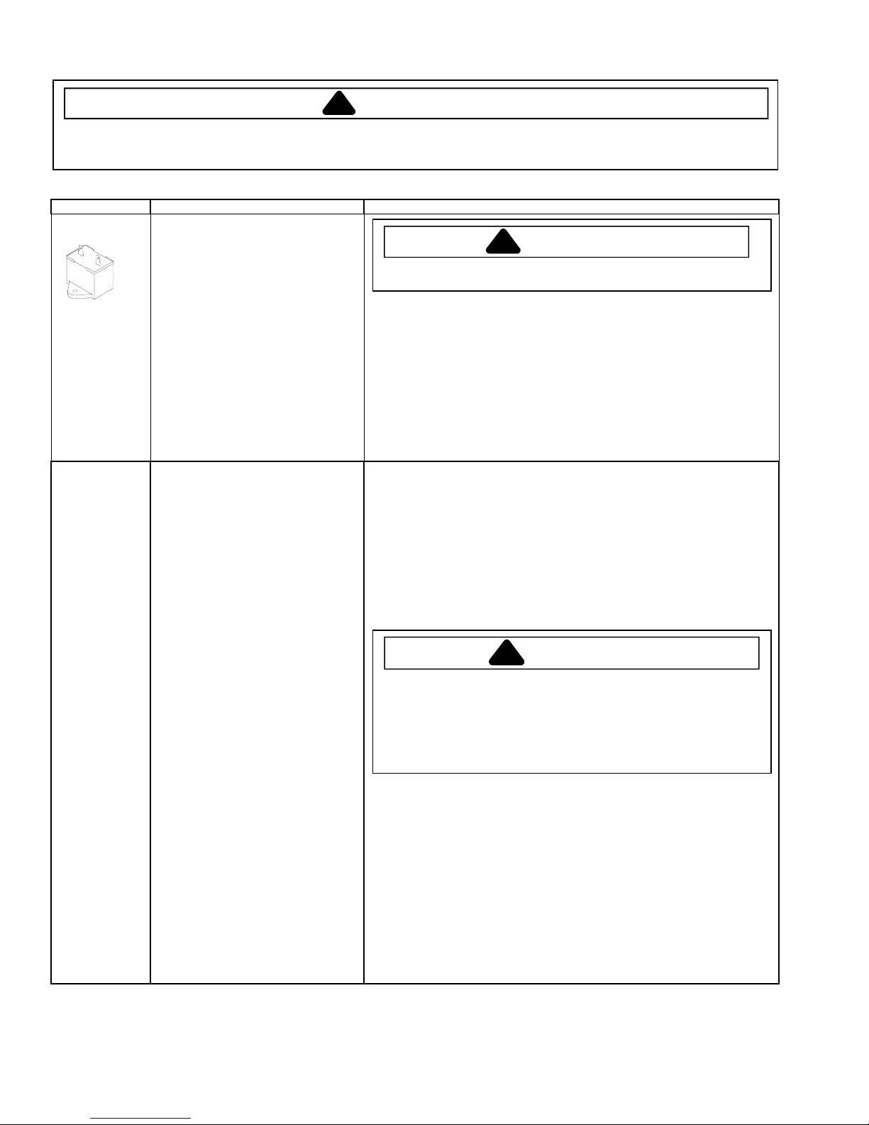
Capacitor
Condenser Condenser is a tube and wire
Run capacitor connects to relay terminal
3 and L side of line.
Some compressors do not require a run
capacitor; refer to the Technical Data
Sheet for the unit being serviced.
construction located in machine
compartment.
Condenser is on high pressure discharge
side of compressor. Condenser function
is to transfer heat absorbed by refrigerant
to ambient.
Higher pressure gas is routed to
condenser where, as gas temperature is
reduced, gas condenses into a high
pressure liquid state. Heat transfer takes
place because discharged gas is at a
higher temperature than air that is
passing over condenser. It is very
important that adequate air flow over
condenser is maintained.
Condenser is air cooled by condenser fan
motor. If efficiency of heat transfer from
condenser to surrounding air is impaired,
condensing temperature becomes higher.
High liquid temperature means liquid will
not remove as much heat during boiling
in evaporator as under normal conditions.
This would be indicated by high than
normal head pressures, long run time,
and high wattage. Remove any lint or
other accumulation, that would restrict
normal air movement through condenser.
From condenser the refrigerant flows into
a post condenser loop which helps
control exterior condensation on flange,
center mullion, and around freezer door.
Refrigerant the flows through the drier to
evaporator and into compressor through
suction line.
To avoid electrical shock which can cause severe personal injury or death,
discharge capacitor through a resistor before handling.
1. Disconnect power to refrigerator.
2. Remove capacitor cover and disconnect capacitor wires.
3. Discharge capacitor by shorting across terminals with a resistor for 1 minute.
4. Check resistance across capacitor terminals with ohmmeter set on “X1K”
scale.
• Good—needle swings to 0 ohms and slowly moves back to infinity.
• Open—needle does not move. Replace capacitor.
• Shorted—needle moves to zero and stays. Replace capacitor.
• High resistance leak—needle jumps toward 0 and then moves back to
constant high resistance (not infinity).
Leaks in condenser can usually be detected by using an electronic leak detector
or soap solution. Look for signs of compressor oil when checking for leaks. A
certain amount of compressor oil is circulated with refrigerant.
Leaks in post condenser loop are rare because loop is a one-piece copper tube.
For minute leaks:
1. Separate condenser from rest of refrigeration system and pressurize
condenser up to a maximum of 16.20 Bar with a refrigerant and dry nitrogen
combination.
2. Recheck for leaks.
To avoid severe personal injury or death from sudden eruption of high
pressures gases, observe the following:
Protect against a sudden eruption if high pressures are required for leak
checking.
Do not use high pressure compressed gases in refrigeration systems
without a reliable pressure regulator and pressure relief valve in the
lines.
WARNING
!
WARNING
!
6 16023324 Rev. 0
©2004 Maytag Services
Page 7
Component Testing
!
WARNING
To avoid risk of electrical shock, personal injury, or death, disconnect electrical power source to unit, unless test
procedures require power to be connected. Discharge capacitor through a resistor before attempting to service.
Ensure all earthing wires are connected before certifying unit as repaired and/or operational.
Component Description Test Procedures
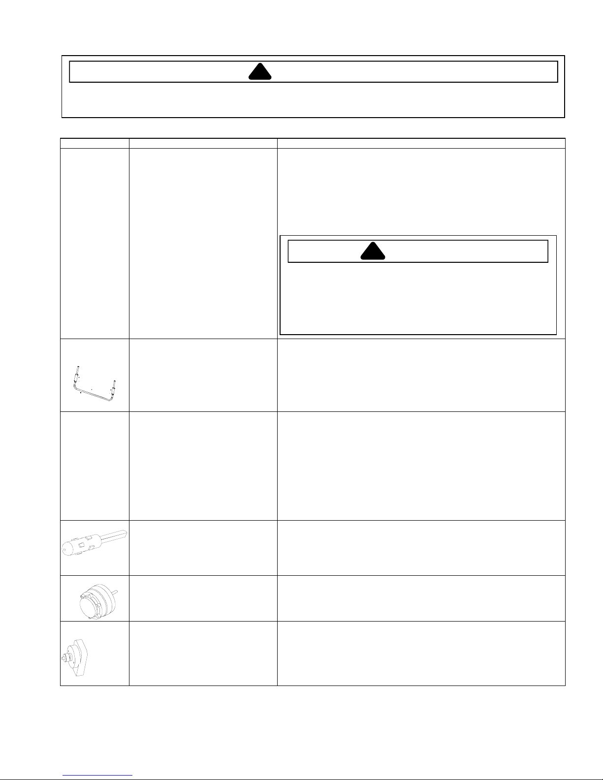
Overload / Relay
Control board
Ice maker Optional on some models.
Evaporator fan
motor
Electric damper
control
When voltage is connected and relay is
cool, current passes through relay to start
winding.
After a short time, current heats the
resistor in relay and resistance will rise
blocking current flow through relay.
Start winding remains in the circuit through
run capacitor.
Solid state relay plugs directly on
compressor start and run terminals. Relay
terminals 2 and 3 are connected within
relay. Run capacitor is connected to relay
terminal 3. L2 side of 120 VAC power is
connected to relay terminal 2.
On some models.
See “Control Board” section for
troubleshooting information.
See “Ice Maker” section for service
information.
Evaporator fan moves air across
evaporator coil and throughout refrigerator
cabinet.
Damper control balances the air delivery
between refrigerator and freezer
compartments providing temperature
control for refrigerator.
Electrical voltage activates damper control
and door closes restricting flow of air from
freezer compartment to refrigerator
compartment.
1. Disconnect power to the refrigerator.
2. Remove relay cover and disconnect leads.
3. Check resistance across terminals 2 and 3 with an ohmmeter:
Normal = 3 to 12 ohms
Shorted = 0 ohms
Open = infinite ohms
1. Disconnect power to unit.
2. Disconnect fan motor leads.
3. Check resistance from ground connection solder. Trace to motor frame must
not exceed .05 ohms.
4. Check for voltage at connector to motor with unit in refrigeration mode and
compressor operating.
Check resistance across terminals.
If no resistance across terminals replace damper control.
©2004 Maytag Services
16023324 Rev. 0 7
Page 8

Component Testing
!
WARNING
To avoid risk of electrical shock, personal injury, or death, disconnect electrical power source to unit, unless test
procedures require power to be connected. Discharge capacitor through a resistor before attempting to service.
Ensure all earthing wires are connected before certifying unit as repaired and/or operational.
Component Description Test Procedures
Switch, refrigerator
light,
Switch, freezer
light
Switch, water
dispenser
Drier
Single pole, single throw switch
completes circuit for light when door is
open.
Single pole, double throw switch
completes circuit for light when door is
open. Opens circuit to icemaker when
door is open.
Single pole, single throw switch
completes circuit for water solenoid when
button is depressed.
Drier is placed at post condenser loop
outlet and passes liquefied refrigerant to
capillary.
Desiccant (20) 8 x 12 4AXH - 7 M>S> Grams
Check resistant across terminals.
Switch arm depressed
“NO” terminals Open
Switch arm up
“NO” terminals Closed
Check resistant across terminals.
Switch arm depressed
“NO” terminals Open
”NC” terminals Closed
Switch arm up
“NO” terminals Closed
“NC” terminals Open
Check resistant across terminals.
Water button not depressed
“NO” terminals Open
Water button depressed
“NO” terminals Closed
Drier must be changed every time the system is opened for testing or
compressor replacement.
NOTE: Drier used in R12 sealed system is not interchangeable with
drier used in R134a sealed system. Always replace drier in R134a
system with Amana part number B2150504.
Before opening refrigeration system, recover HFC134a refrigerant for safe
disposal.
1. Cut drier out of system using the following procedure. Do not unbraze drier.
2. Applying heat to remove drier will drive moisture into the system.
3. Score capillary tube close to drier and break.
4. Reform inlet tube to drier allowing enough space for large tube cutter.
5. Cut circumference of drier 31.75 mm below condenser inlet tube joint to drier.
6. Remove drier.
7. Apply heat trap paste on post condenser tubes to protect grommets from high
heat.
8. Unbraze remaining part of drier. Remove drier from system.
9. Discard drier in safe place. Do not leave drier with customer. If refrigerator is
under warranty, old drier must accompany warranty claim.
To avoid death or severe personal injury, cut drier at correct location.
Cutting drier at incorrect location will allow desiccant beads to scatter. If
spilled, completely clean area of beads.
WARNING
!
8 16023324 Rev. 0
©2004 Maytag Services
Page 9
Component Testing
!
WARNING
To avoid risk of electrical shock, personal injury, or death, disconnect electrical power source to unit, unless test
procedures require power to be connected. Discharge capacitor through a resistor before attempting to service.
Ensure all earthing wires are connected before certifying unit as repaired and/or operational.
Component Description Test Procedures
Evaporator Inner volume of evaporator allows liquid
Evaporator heater
(defrost)
Thermostat
(defrost)
Thermistor
Condenser motor
ECM condenser
motor
refrigerant discharged from capillary to
expand into refrigerant gas.
Expansion cools evaporator tube and fin
temperature to approximately -20°F
transferring heat from freezer section to
refrigerant.
Passing through suction line to
compressor, the refrigerant picks up
superheat (a relationship between
pressure and temperature that assures
complete vaporization of liquid
refrigerant) as the result of capillary tube
soldered to suction line.
Refrigerant gas is pulled through suction
line by compressor, completing
refrigeration cycle.
Activated when defrost thermostat,
defrost timer, and freezer control
complete circuit through heater.
Thermostat is in a series circuit with
terminal 2 of defrost timer, and defrost
heater. Circuit is complete if evaporator
fan motor operates when cold.
Controls the circuit from freezer
thermostat through defrost terminator to
defrost heater. Opens and breaks circuit
when thermostat senses preset high
temperature.
Temperature sensing device Check resistance across leads.
Condenser fan moves cooling air across
condenser coil and compressor body.
Condenser fan motor is in parallel circuit
with compressor.
Condenser fan moves cooling air across
condenser coil and compressor body.
Condenser fan motor is in parallel circuit
with compressor.
Test for leaks in evaporator with electronic leak detector or with soap solution.
Compressor oil is circulated with refrigerant; check for oil when checking for
leaks.
For minute leaks:
1. Separate evaporator from rest of refrigeration system and pressurize
evaporator up to a maximum of 9.65 Bar with a refrigerant and dry nitrogen
combination.
2. Recheck for leaks.
WARNING
!
To avoid severe personal injury or death from sudden eruption of high
pressures gases, observe the following:
Protect against a sudden eruption if high pressures are required for leak
checking.
Do not use high pressure compressed gases in refrigeration systems
without a reliable pressure regulator and pressure relief valve in the
lines.
Check resistance across heater.
To check defrost system:
1. Thermocouple defrost thermostat and plug refrigerator into wattmeter.
2. Turn into defrost mode. Wattmeter should read specified watts (according to
Technical Data Sheet).
3. When defrost thermostat reaches specified temperature ±15°C (see
Technical Data Sheet), thermostat should interrupt power to heater.
Test continuity across terminals.
With power off and evaporator coil below freezing, thermostat should show
continuity when checked with ohmmeter. See “Heater, evaporator (defrost)”
section for additional tests.
After defrost thermostat opens, thermostat remains open until end of defrost cycle
and refrigerator starts cooling again. Defrost thermostat senses a preset low
temperature and resets (closes).
Temperature Resistance
25°C 10,000 ohms
2.2°C 29,500 ohms
-17.7°C 86,300 ohms
Check resistance across coil.
Check resistance across coil.
©2004 Maytag Services
16023324 Rev. 0 9
Page 10
Service Procedures
!
WARNING
To avoid risk of electrical shock, personal injury, or death, disconnect electrical power source to unit, unless test
procedures require power to be connected. Discharge capacitor through a resistor before attempting to service.
Ensure all earthing wires are connected before certifying unit as repaired and/or operational.
Service Equipment
Listed below is equipment needed for proper servicing
of HFC134a systems. Verify equipment is confirmed
by manufacturer as being compatible with HFC134a
and ester oil system.
Equipment must be exclusively used for HFC134a.
Exclusive use of equipment only applies to italic items.
• Evacuation pump
Check with vacuum pump supplier to verify equipment
is compatible for HFC134a. Robinair, Model 15600
2 stage, 6 cubic feet per minute pump is
recommended.
• Four-way manifold gauge set, with low loss hoses
• Leak detector
•
Charging cylinder
• Line piercing saddle valve
(Schroeder valves). Seals must be HFC134a and
ester oil compatible. Line piercing valves may be used
for diagnosis but are not suitable for evacuation or
charging, due to minute holes pierced in tubing. Do
not leave mechanical access valves on system.
Valves eventually will leak. Molecules of HFC134a are
smaller than other refrigerants and will leak where
other refrigerants would not.
• Swagging tools
•
Flaring tools
• Tubing cutter
• Flux
• Sil-Fos
• Silver solder
• Oil for swagging and flaring
Use only part # R0157532
• Copper tubing
Use only part # R0174075 and # R0174076
• Dry nitrogen
99.5% minimum purity, with -40°C or lower dew point
• Crimp tool
• Tube bender
• Micron vacuum gauge
• Process tube adaptor kit
• Heat trap paste
• ICI appliance grade HFC134a
Drier Replacement
Before opening refrigeration system, recover
HFC134a refrigerant for safe disposal.
Every time sealed HFC134a system is repaired, drier
filter must be replaced with, part # B2150504.
Cut drier out of system by completing the following
steps. Do not unbraze drier filter. Applying heat to
remove drier will drive moisture into system.
WARNING
!
To avoid risk of severe personal injury or death, cut
drier at correct location. Cutting drier at incorrect
location will allow desiccant beads to scatter.
Completely clean area of beads, if spilled.
1. Score capillary tube close to drier and break.
2. Reform inlet tube to drier allowing enough space
for large tube cutter.
3. Cut circumference of drier at 31.75 millimeters,
below condenser inlet tube joint to drier.
4. Remove drier.
5. Apply heat trap paste on post condenser tubes to
protect grommets from high heat.
6. Unbraze remaining part of drier. Remove drier
from system.
7. Discard drier in safe place. Do not leave drier with
customer. If refrigerator is under warranty, old
drier must accompany warranty claim.
10 16023324 Rev. 0 ©2004 Maytag Services
Page 11
Service Procedures
!
WARNING
To avoid risk of electrical shock, personal injury, or death, disconnect electrical power source to unit, unless test
procedures require power to be connected. Discharge capacitor through a resistor before attempting to service.
Ensure all earthing wires are connected before certifying unit as repaired and/or operational.
Refrigerant Precautions
WARNING
!
To avoid risk of personal injury, do not allow
refrigerant to contact eyes or skin.
CAUTION
!
To avoid risk of property damage, do not use
refrigerant other than that shown on unit serial
number identification plate.
NOTE: All precautionary measures recommended by
refrigerant manufacturers and suppliers apply
and should be observed.
Line Piercing Valves
Line piercing valves can be used for diagnosis, but
are not suitable for evacuating or charging due to
holes pierced in tubing by valves.
NOTE: Do not leave line piercing valves on system.
Connection between valve and tubing is not
hermetically sealed. Leaks will occur.
Open Lines
During any processing of refrigeration system, never
leave lines open to atmosphere. Open lines allow water
vapor to enter system, making proper evacuation more
difficult.
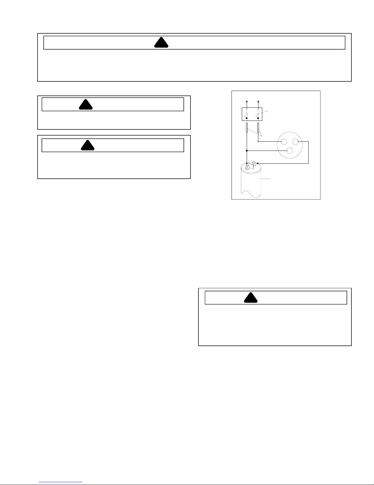
Compressor Operational Test
(short term testing only)
If compressor voltage, capacitor, overload, and motor
winding tests are successful (do not indicate a fault),
perform the following test:
1.Disconnect power to unit.
2.Discharge capacitor by shorting capacitor
terminals through a resistor.
NOTE: Not all units have run capacitor.
3.Remove leads from compressor terminals.
4.Attach test cord to compressor windings.
• Common lead on test cord attaches to C terminal
on compressor.
• Start lead on test cord attaches to S terminal on
compressor.
• Run lead on test cord attaches to M terminal on
compressor.
To AC supply
Switch
Compressor
Fuses
Attaching Capacitor for Compressor Test
5. Connect a known good capacitor into circuit as shown
above. For proper capacitor size and rating, see
technical data sheet for unit under test.
NOTE: Ensure test cord cables and fuses meet
specifications for unit under test (see Technical
Sheet for unit under test).
6. Replace compressor protector cover securely.
7. Plug test cord into outlet, then press and release start
cord switch.
CAUTION
!
To avoid risk of damage to compressor windings,
immediately disconnect (unplug) test cord from power
source if compressor does not start. Damage to
compressor windings occurs if windings remain
energized when compressor is not running.
If compressor runs when direct wired, it is working
properly. Malfunction is elsewhere in system.
If compressor does not start when direct wired, recover
system at high side. After the system is recovered,
repeat compressor direct wire test.
If compressor runs after system is recovered (but
would not operate when wired direct before recovery) a
restriction in sealed system is indicated.
If motor does not run when wired direct after recovery,
replace faulty compressor.
CRS
Capacitor
©2004 Maytag Services 16023324 Rev. 0 11
Page 12
Service Procedures
!
WARNING
To avoid risk of electrical shock, personal injury, or death, disconnect electrical power source to unit, unless test
procedures require power to be connected. Discharge capacitor through a resistor before attempting to service.
Ensure all earthing wires are connected before certifying unit as repaired and/or operational.
Dehydrating Sealed Refrigeration System
Moisture in a refrigerator sealed system exposed to
heat generated by the compressor and motor reacts
chemically with refrigerant and oil in the system and
forms corrosive hydrochloric and hydrofluoric acids.
These acids contribute to breakdown of motor winding
insulation and corrosion of compressor working parts,
causing compressor failure.
In addition, sludge, a residue of the chemical reaction,
coats all surfaces of sealed system, and will eventually
restrict refrigerant flow through capillary tube.
To dehydrate sealed system, evacuate system (see
paragraph
Evacuation
).
Leak Testing
DANGER
!
To avoid risk of serious injury or death from violent
explosions, NEVER use oxygen or acetylene for
pressure testing or clean out of refrigeration
systems. Free oxygen will explode on contact with
oil. Acetylene will explode spontaneously when put
under pressure.
Testing Systems Containing No Refrigerant Charge
1. Connect cylinder of nitrogen, through gauge
manifold, to process tube of compressor and liquid
line strainer.
2. Open valves on nitrogen cylinder and gauge manifold.
Allow pressure to build within sealed system.
3. Check for leaks using soap suds.
If a leak is detected in a joint, do not to attempt to repair
by applying additional brazing material. Joint must be
disassembled, cleaned and rebrazed. Capture refrigerant
charge (if system is charged), unbraze joint, clean all
parts, then rebraze.
If leak is detected in tubing, replace tubing. If leak is
detected in either coil, replace faulty coil.
It is important to check sealed system for refrigerant
leaks. Undetected leaks can lead to repeated service
calls and eventually result in system contamination,
restrictions, and premature compressor failure.
Refrigerant leaks are best detected with halide or
electronic leak detectors.
Testing Systems Containing a Refrigerant Charge
1. Stop unit operation (turn refrigerator off).
2. Holding leak detector exploring tube as close to
system tubing as possible, check all piping, joints,
and fittings.
NOTE: Use soap suds on areas leak detector cannot
reach or reliably test.
12 16023324 Rev. 0 ©2004 Maytag Services
Page 13

Service Procedures
!
WARNING
To avoid risk of electrical shock, personal injury, or death, disconnect electrical power source to unit, unless test
procedures require power to be connected. Discharge capacitor through a resistor before attempting to service.
Ensure all earthing wires are connected before certifying unit as repaired and/or operational.
Restrictions
Symptoms
Restrictions in sealed system most often occur at
capillary tube or filter drier, but can exist anywhere on
liquid side of system.
Restrictions reduce refrigerant flow rate and heat
removal rate. Wattage drops because compressor is
not circulating normal amount of refrigerants.
Common causes of total restrictions are moisture,
poorly soldered joints, or solid contaminants. Moisture
freezes at evaporator inlet end of capillary tube. Solid
contaminants collect in filter drier.
If restriction is on low side, suction pressure will be in a
vacuum and head pressure will be near normal.
If restriction is on high side, suction pressure will be in
a vacuum and head pressure will be higher than
normal during pump out cycle.
Refrigeration occurs on low pressure side of partial
restriction. There will be a temperature difference at
the point of restriction. Frost and/or condensation will
be present in most case at the point of restriction.
Also, system requires longer to equalize.
Slight or partial restriction can give the same
symptoms as refrigerant shortage including lower than
normal back pressure, head pressure, wattage, and
warmer temperatures.
Total restriction on the discharge side of compressor,
when restriction is between compressor and first half
of condenser, results in higher than normal head
pressure and wattage while low side is being pumped
out.
Testing for Restrictions
To determine if a restriction exists:
1. Attach gauge and manifold between suction and
discharge sides of sealed system.
2. Turn unit on and allow pressure on each side to
stabilize. Inspect condenser side of system. Tubing
on condenser should be warm and temperature
should be equal throughout (no sudden drops at any
point along tubing).
• If temperature of condenser tubing is consistent
throughout, go to step 4.
• If temperature of condenser tubing drops suddenly
at any point, tubing is restricted at point of
temperature drop (if restriction is severe, frost may
form at point of restriction and extend down in
direction of refrigerant flow in system). Go to step 5.
3. Visually check system for kinks in refrigeration line
which is causing restriction. Correct kink and repeat
step 2.
4. Turn unit off and time how long it takes high and low
pressure gauges to equalize:
• If pressure equalization takes longer than 10
minutes, a restriction exists in the capillary tube or
drier filter. Go to step 5.
• If pressure equalization takes less than 10 minutes,
system is not restricted. Check for other possible
causes of malfunction.
5. Recover refrigerant in sealed system.
NOTE: Before opening any refrigeration system,
capture refrigerant in system for safe disposal.
6. Remove power from unit.
CAUTION
!
To avoid risk of personal injury or property damage,
take necessary precautions against high
temperatures required for brazing.
7. Remove and replace restricted device.
8. Evacuate sealed system.
9. Charge system to specification.
NOTE: Do not use captured or recycled refrigerant in
units. Captured or recycled refrigerant voids any
compressor manufacturer's warranty.
NOTE: Charge system with exact amount of refrigerant.
Refer to unit nameplate for correct refrigerant
charge. Inaccurately charged system will cause
future problems.
©2004 Maytag Services 16023324 Rev. 0 13
Page 14

Service Procedures
!
WARNING
To avoid risk of electrical shock, personal injury, or death, disconnect electrical power source to unit, unless test
procedures require power to be connected. Discharge capacitor through a resistor before attempting to service.
Ensure all earthing wires are connected before certifying unit as repaired and/or operational.
Evacuation and Charging
CAUTION
!
To avoid risk of fire, sealed refrigeration system
must be air free. To avoid risk of air contamination,
follow evacuation procedures exactly.
NOTE: Before opening any refrigeration system, EPA
regulations require refrigerant in system to be
captured for safe disposal.
Proper evacuation of sealed refrigeration system is an
important service procedure. Usable life and
operational efficiency greatly depends upon how
completely air, moisture and other non-condensables
are evacuated from sealed system.
Air in sealed system causes high condensing
temperature and pressure, resulting in increased
power requirements and reduced performance.
Moisture in sealed system chemically reacts with
refrigerant and oil to form corrosive hydrofluoric and
hydrochloric acids. These acids attack motor windings
and parts, causing premature breakdown.
Before opening system, evaporator coil must be at
ambient temperature to minimize moisture infiltration
into system.
Evacuation
To evacuate sealed refrigeration system:
1. Connect vacuum pump, vacuum tight manifold set
with high vacuum hoses, thermocouple vacuum
gauge and charging cylinder as shown in illustration.
Evacuation should be done through I.D. opening of
tubes not through line piercing valve.
2. Connect low side line to compressor process tube.
3. Connect high side line to drier/process tube.
4. Evacuate both simultaneously. With valve “C” and “F”
closed, open all other valves and start vacuum pump.
Thermistor
Vacuum Gauge
Compressor
Low Side Gauge
Charging Hose
Compressor
Process
Tube
.6 cm Copper
Tubing
Valve
Vacuum Pump
Equipment Setup For Evacuation And Charging
5. After compound gauge (low side) drops to
approximately .98 Bar, open valve “C” to vacuum
thermocouple gauge and take micron reading.
NOTE: A high vacuum pump can only produce a good
vacuum if oil in pump is not contaminated.
6. Continue evacuating system until vacuum gauge
registers 600 microns.
7. At 600 microns, close valve “A” to vacuum pump and
allow micron reading in system to balance. Micron
level will rise.
• If in 2 minutes, micron level stabilizes at 1000
microns or below, system is ready to be charged.
• If micron level rises above 1000 microns and
stabilizes, open valve “A” and continue evacuating.
• If micron reading rises rapidly and does not
stabilize, a leak still exists in system.
Close valve “A” to vacuum pump and valve “C” to
vacuum gauge. Invert charging cylinder and open
charging cylinder valve “F” to add partial charge for
leak checking. With leak detector, check manifold
connections and system for leaks. After locating
leak, capture refrigerant, repair leak, and begin at
step 1.
E
High Side Gauge
D
Valve
Charging Hose
C
B
A
Drier/Process Tu be
Charging
Cylinder
F
Valve
14 16023324 Rev. 0 ©2004 Maytag Services
Page 15

Service Procedures
!
WARNING
To avoid risk of electrical shock, personal injury, or death, disconnect electrical power source to unit, unless test
procedures require power to be connected. Discharge capacitor through a resistor before attempting to service.
Ensure all earthing wires are connected before certifying unit as repaired and/or operational.
Charging
NOTE: Do not use captured or recycled refrigerant in
units. Captured or recycled refrigerant voids any
warranty.
NOTE: Charge system with exact amount of refrigerant.
Refer to unit serial plate for correct refrigerant
charge. Inaccurately charged system will cause
future problems.
To charge system:
1. Close valves “A” to vacuum pump and “C” to vacuum
gauge and “E” to low side manifold gauge.
2. Set scale on dial-a-charge cylinder for corresponding
HFC134a pressure reading.
3. Open valve “F” to charging cylinder and let exact
amount of refrigerant flow from cylinder into system.
Close valve.
Low side gauge pressure should rise shortly after
opening charging cylinder valve as system pressure
equalizes through capillary tube.
If pressure does not equalize, a restriction typically
exists at capillary/drier braze joint.
4. If pressure equalizes, open valve “E” to low side
manifold gauge and pinch off high side drier process
tube.
5. Start compressor and draw remaining refrigerant from
charging hoses and manifold into compressor
through compressor process tube.
6. To check high side pinch-off drier process tube. Close
valve “D” to high side gauge. If high side pressure
rises, repeat high side pinch-off and open valve “D”.
Repeat until high side pinch-off does not leak.
7. Pinch-off compressor process tube and remove
charging hose. Braze stub closed while compressor is
operating.
8. Disconnect power. Remove charging hose and braze
high side drier process tube closed.
9. Recheck for refrigerant leaks.
Refrigerant Charge
Refrigerant charge in all capillary tube systems is
critical and exact amount is required for proper
performance. Factory charges are shown on serial
plate.
NOTE: Do not use refrigerant other than shown on
serial plate.
©2004 Maytag Services 16023324 Rev. 0 15
Page 16

Service Procedures
!
WARNING
To avoid risk of electrical shock, personal injury, or death, disconnect electrical power source to unit, unless test
procedures require power to be connected. Discharge capacitor through a resistor before attempting to service.
Ensure all earthing wires are connected before certifying unit as repaired and/or operational.
HFC134a Service Information
CAUTION
HFC134a is alternative refrigerant for CFC12.
HFC134a has an ozone depletion potential (ODP)
factor of 0.0 and a global warming potential (GWP)
To minimize contamination, exercise extreme care
when servicing HFC134A sealed systems.
factor of 0.27. HFC134a is not flammable and has
acceptable toxicity levels. HFC134a is not
interchangeable with CFC12. There are significant
differences between HFC134a and CFC12 which must
be considered when handling and processing
refrigeration system.
Health, Safety, and Handling
Health, safety and handling considerations for
HFC134A are virtually no different than those for
CFC12.
Health, Safety, and
Handling
Allowable overall
exposure limit
Vapor exposure to skin No effect Same
Liquid exposure to skin Can cause frostbite Same
Vapor exposure to eye Very slight eye irritant Same
Liquid exposure to eye Can cause frostbite Same
Above minimum exposure
limit
Safety and handling Wear appropriate skin
Spill management Remove or extinguish
Fire explosion hazards May decompose if
Disposal procedures Recycle or reclaim. Same
1,000 ppm Same
Can cause Asphyxiation,
Tachycardia, and Cardia
Arrhythmias
and eye protection. Use
with adequate
ventilation.
ignition or combustion
sources. Evacuate or
ventilate area.
contact with flames and
heating elements.
Container may explode
if heated due to resulting
pressure rise.
Combustion products
are toxic.
CFC12 HFC134a
Same
Same
Same
Same
• No trace of other refrigerants is allowed in HFC134a
systems. Chlorinated molecules in other refrigerants
such as CFC12, etc. will lead to capillary tube
plugging.
• Ester oil is used in HFC134a systems. Do not use
mineral oil. HFC134a and mineral oils cannot be
mixed. If mineral oils were used in HFC134a systems,
lubricant would not return to compressor and would
cause early compressor failure. If significant amount of
oil has been lost from compressor, replace oil rather
than adding oil.
• Ester oils used in HFC134a systems are so
hydroscopic that by the time an inadequate system
performance is detected, oil will be saturated with
moisture.
• CFC12 has much higher tolerance to system
processing materials, such as drawing compounds,
rust inhibitors, and cleaning compounds, than
HFC134a. Such materials are not soluble in HFC134a
systems. If materials were to be washed from system
surfaces by ester oils, they could accumulate and
eventually plug capillary tube.
• Care must be taken to minimize moisture entering
HFC134a system. Do not leave compressor or system
open to atmosphere for more than 10 minutes.
Excessive moisture in HFC134a system will react with
compressor oil and generate acid.
• Compressor must be replaced when performing low
side leak repair.
• Drier filter must always be replaced with service drier
filter, part #B2150504.
Important: Unbrazing drier filter from tubing will drive
Comparison of CFC12 and HFC134a Properties
Properties/Characteristics CFC12 HFC134a
Ozone Depletion Potential
(ODP)
Global Warming Potential
(GPW)
Molecular weight 121 102
Boiling point at 1 atmosphere -22°F (-30°C) -15°F (-
Vapor pressure at 77°F
(25°C)
Liquid density at 77°F (25°C) 82 lb/ft
Flammability No No
High-side system operating
Pressure at 65°F (18°C)
Low-side system operating
Pressure at 65°F (18°C)
1.0* 0.0*
3.2* 0.27*
80 psig 82 psig
3
HFC134a approximately 3 psig
higher than CFC12
HFC134a approximately 2 psig
lower than CFC12
126°C)
75 lb/ft
3
moisture from desiccant and into system, causing
acids to form. Do not unbraze filter drier from tubing. If
CFC12 service drier was installed in HFC134A system,
drier could overload due to excessive moisture.
• HFC134a compatible copper tubing, part #R0174075
.635 millimeter x 457.2 millimeter length and part
#R0174076 7.93 millimeter x 609.6 millimeter must be
used when replacing tubing.
• Avoid system contamination by using Towerdraw E610
evaporating oil, part # R0157532, when flaring,
swagging, or cutting refrigeration tubing.
16 16023324 Rev. 0 ©2004 Maytag Services
!
Page 17

Service Procedures
!
WARNING
To avoid risk of electrical shock, personal injury, or death, disconnect electrical power source to unit, unless test
procedures require power to be connected. Discharge capacitor through a resistor before attempting to service.
Ensure all earthing wires are connected before certifying unit as repaired and/or operational.
Replacement Service Compressor
HFC134a service compressors will be charged with
ester oil and pressurized with dry nitrogen. Before
replacement compressor is installed, pull out 1 rubber
plug. A
a
Positive pressure in compressor is vital to keep
moisture out of ester oil. Do not leave compressor
open to atmosphere for more than 10 minutes.
Compressor Testing Procedures
Refer to Technical Data Sheet “Temperature
Relationship Chart” for operating watts, test points,
and temperature relationship test for unit being tested.
• Temperature testing is accomplished by using 3 lead
• Thermocouple tips should be attached securely to
• Do not test during initial
• Refrigerator must operate minimum of 20 minutes
• Turn control to colder to obtain required on time.
• Wattage reading must be recorded in conjunction with
• Suction and head pressures are listed on
pop
from pressure release should be heard. If
pop
sound is not heard, do not use compressor.
WARNING
!
To avoid death or severe personal injury, never use
oxygen, air or acetylene for pressure testing or
clean out of refrigeration system. Use of oxygen,
air, or acetylene may result in violent explosion.
Oxygen may explode on contact with oil and
acetylene will spontaneously explode when under
pressure.
thermocouple temperature tester in specific locations.
Test point T-1 is outlet on evaporator coil and T-2 is
inlet. Test point T-3 is suction tube temperature
midway between where armaflex ends and suction
port of compressor (approximately 304.8 millimeters
from compressor).
specified locations.
pull down
or balanced temperature condition to occur before
proceeding with testing.
after thermocouples are installed.
temperature test to confirm proper operation.
“Temperature and Relationship Chart”. Normally these
are not required for diagnosis but used for confirmation
on systems which have been opened.
. Allow one off cycle
Brazing
CAUTION
!
To avoid risk of personal injury or property damage,
take necessary precautions against high
temperatures required for brazing.
Satisfactory results require cleanliness, experience,
and use of proper materials and equipment.
Connections to be brazed must be properly sized, free
of rough edges, and clean.
Generally accepted brazing materials are:
• Copper to copper joints: SIL-FOS (alloy of 15
percent silver, 80 percent copper, and 5 percent
phosphorous). Use without flux. Recommended
brazing temperature is approximately 760°C. Do not
use for copper to steel connection.
• Copper to steel joints: SILVER SOLDER (alloy of 30
percent silver, 38 percent copper, 32 percent zinc).
Use with fluoride based flux. Recommended brazing
temperature is approximately 649°C.
• Steel to steel joints: SILVER SOLDER (see copper
to steel joints).
• Brass to copper joints: SILVER SOLDER (see
copper to steel joints).
• Brass to steel joints: SILVER SOLDER (see copper
to steel joints).
©2004 Maytag Services 16023324 Rev. 0 17
Page 18

Refrigerant Flow
R
CAPILLARY
TUBE
Note: Capillary Tube and
Suction Tube are
located under Fresh
SUCTION
Food floor.
TUBE
EVAPORATOR
COMPRESSOR
DISCHARGE
TUBE
CONDENSER
POST CONDENSE
TUBE
DRYER
PROCESS
TUBE
18 16023324 Rev. 0 ©2004 Maytag Services
Bottom Mount
Refrigerant Flow Diagram
Page 19

Cabinet Air Flow
REFRIGERATOR
RETURN AIR
TUNNELS
REFRIGERATOR AIR
SUPPLY TUNNEL TO
FRESH FOOD COMPARTMENT
CONTROL DAMPER
CRISPER AIR
SUPPLY PORT
EVAPORATOR FAN
ASSEMBLY
FREEZER AIR
SUPPLY GRILLE
EVAPORATOR
EVAPORATOR
COVER
FREEZER RETURN AIR
THOUGH LOUVERS AT
BOTTOM OF EVAPORATOR
COVER
Bottom Mount
Cabinet Air Flow Diagram
©2004 Maytag Services 16023324 Rev. 0 19
Page 20

Machine Compartment Air Flow
Compressor
Condenser
Condenser Fan
Assembly
Two Way Bottom Mount
Machine Compartment Air Flow Diagram
20 16023324 Rev. 0 ©2004 Maytag Services
Page 21

Machine Compartment Air Flow
©2004 Maytag Services 16023324 Rev. 0 21
One Way Bottom Mount
Machine Compartment Air Flow Diagram
Page 22

Typical External Sweat Pattern
g
CLASSIFICATION OF
CONDENSATION
1 = Haze or fog
2 = Beading
3 = Beads or small drops
4 = Drops runnin
Conditions after 4 hour
Laboratory Sweat Test.
Ambient: 90 dF
Relative humidity 84%
Refrigerator Temp. 40 dF
Freezer Temp. 0 dF
together
# 1
Refrigerator
door bottom
Center
mullion
Freezer
door top
Freezer
door bottom
# 1
# 2
# 1
No sweat on side
when compressor
is running
# 2
22 16023324 Rev. 0 ©2004 Maytag Services
Page 23

Troubleshooting Chart
!
WARNING
To avoid risk of electrical shock, personal injury, or death, disconnect electrical power source to unit, unless test
procedures require power to be connected. Discharge capacitor through a resistor before attempting to service.
Ensure all earthing wires are connected before certifying unit as repaired and/or operational.
Troubleshooting chart on following pages contains symptoms that may be seen in malfunctioning units. Each
symptom is accompanied by one or more possible causes and by a possible remedy or test to determine if
components are working properly.
Symptom Possible Causes Corrective Action
Unit does not run
Refrigerator section too warm
No power to unit Check for power at outlet. Check
fuse box/circuit breaker for blown
fuse or tripped breaker. Replace or
reset.
Faulty power cord Check with test light at unit; if no
circuit and current is indicated at
outlet, replace or repair.
Low voltage Check input voltage for proper
voltage. Take appropriate action to
correct voltage supply problem.
Faulty motor Check all connections are tight and
secure.
Jumper across terminals of control. If
unit runs, replace control.
Faulty relay Check relay. Replace if necessary.
Faulty compressor Check compressor motor windings
for opens/shorts.
Perform compressor direct wiring
test.
Replace if necessary.
Faulty overload Check overload for continuity.
NOTE: Ensure
compressor/overload are below
trip temperature before testing.
Replace if necessary.
Excessive door opening Consumer education
Overloading of shelves Consumer education
Warm or hot foods placed in cabinet Consumer education
Cold control set too warm Set control to colder setting.
Poor door seal Level cabinet. Adjust hinges.
Replace gasket.
Refrigerator airflow Check damper is opening by
removing grille. With door open,
damper should open. Replace if
faulty.
Turn control knob to colder position.
Interior light remains on Check switch. Replace if necessary.
Faulty condenser fan or evaporator
fan
Faulty compressor Replace compressor.
Check fan and wiring. Replace if
necessary.
©2004 Maytag Services 16023324 Rev. 0 23
Page 24

Troubleshooting Chart
!
WARNING
To avoid risk of electrical shock, personal injury, or death, disconnect electrical power source to unit, unless test
procedures require power to be connected. Discharge capacitor through a resistor before attempting to service.
Ensure all earthing wires are connected before certifying unit as repaired and/or operational.
Symptom Possible Causes Corrective Action
Refrigerator section too cold
Freezer and refrigerator sections too
warm
Unit runs continuously
Unit runs continuously. Temperature
normal.
Unit runs continuously. Temperature
too cold.
Noisy operation
Refrigerator temperature control set
too cold
Refrigerator airflow not properly
adjusted
Temperature controls set too warm Reset temperature controls.
Poor door seal Level cabinet. Adjust hinges.
Dirty condenser or obstructed grille Check condenser and grille. Clean.
Faulty control Test control. Replace if failed.
Refrigerant shortage or restriction Check for leak or restriction. Repair,
Freezer temp control set too cold Adjust freezer temperature control. Freezer section too cold
Faulty control Test control. Replace if failed.
Temperature control set too cold Adjust temperature control.
Dirty condenser or obstructed grille Check condenser and grille. Clean.
Poor door seal Level cabinet. Adjust hinges.
Interior light remains on Check switch. Replace if necessary.
Faulty condenser fan or evaporator
fan
Faulty control Test control. Replace if failed.
Refrigerant shortage or restriction Check for leak or restriction. Repair,
Refrigerant overcharge Check for overcharge. Evacuate and
Air in system Check for low side leak. Repair,
Ice on evaporator See “Ice on evaporator”.
Faulty defrost thermostat Check thermostat. Replace if
Loose flooring or floor not firm Repair floor or brace floor.
Cabinet not level Level cabinet.
Tubing in contact with cabinet, other
tubing, or other metal
Drip pan vibrating Adjust drain pan.
Fan hitting another part Ensure fan properly aligned and all
Worn fan motor bearings Check motor for loss of lubricant or
Compressor mounting grommets
worn or missing. Mounting hardware
loose or missing
Free or loose parts causing or
allowing noise during operation
24 16023324 Rev. 0 ©2004 Maytag Services
Adjust refrigerator temperature
control.
Check air flow.
Replace gasket.
evacuate and recharge system.
Replace gasket.
Check fan and wiring. Replace if
necessary.
evacuate and recharge system.
recharge system.
evacuate and recharge system.
necessary.
Adjust tubing.
attaching hardware and brackets are
tight and not worn. Tighten or
replace.
worn bearings. Replace if necessary.
Tighten hardware. Replace
grommets if necessary.
Inspect unit for parts that may have
worked free or loose or missing
screws. Repair as required.
Page 25

Troubleshooting Chart
!
WARNING
To avoid risk of electrical shock, personal injury, or death, disconnect electrical power source to unit, unless test
procedures require power to be connected. Discharge capacitor through a resistor before attempting to service.
Ensure all earthing wires are connected before certifying unit as repaired and/or operational.
Symptom Possible Causes Corrective Action
Frost or ice on evaporator
Unit starts and stops frequently
(cycles on and off)
Defrost thermostat faulty Check defrost thermostat. Replace if
failed.
Evaporator fan faulty Check fan motor. Replace if failed.
Defrost heater remains open Check defrost heater continuity.
Replace if failed.
Open wire or connector Check wiring and connections.
Repair as necessary.
Refrigerant shortage or restriction Check for leak or restriction. Repair,
evacuate and recharge system.
Loose wire or thermostat
connections
Supply voltage out of specification Check input voltage. Correct any
Overload protector open Check overload protector for
Faulty compressor motor capacitor
(some compressors do not require
motor capacitor)
Faulty fan motor Check fan motor. Replace if failed.
Restricted air flow Check condenser and grille for dirt.
Refrigerant shortage or restriction Check for leak or restriction. Repair,
Check wiring and connections.
Repair as necessary.
supply problems.
continuity. If open, replace overload.
NOTE: Ensure
overload/compressor are below
trip temperature before testing.
Check capacitor for open/short.
Replace if necessary.
NOTE: Discharge capacitor
before testing.
Clean.
evacuate and recharge system.
©2004 Maytag Services 16023324 Rev. 0 25
Page 26

System Diagnosis
SUCTION
PRESSURE
CONDITION
Refrigerant
Overcharge
Shortage of
Refrigerant
Partial
Restriction
Air in System Near Normal Increase Warmer Warmer Warmer Increase
Low Ambient
Installations
(High
Ambients the
Reverse)
Additional
Heat Load
VARIATION
FROM
NORMAL
Increase Increase Warmer Warmer Colder Increase
Decrease
Decrease
Decrease Decrease Colder Warmer Warmer Decrease
Increase Increase Warmer Warmer Warmer Increase
HEAD
PRESSURE
VARIATION
FROM
NORMAL
Decrease or
Increase
See Text
Decrease or
Increase
See Text
Note 2
T1 INLET
TEMPERATURE
VARIATION
FROM NORMAL
Colder Warmer Warmer Decrease
Colder Warmer Warmer Decrease
T2 OUTLET
TEMPERATURE
VARIATION
FROM NORMAL
T3 SUCTION
TEMPERATURE
VARIATION
FROM NORMAL
WATTAGE
VARIATION
FROM
NORMAL
Inefficient
Compressor
Increase
Normal or
Decrease
Warmer or
Colder
Symptoms of an Overcharge
• Above normal freezer temperatures.
• Longer than normal or continuous run.
• Freezing in refrigerator.
• Higher than normal suction and head pressure.
• Higher than normal wattage.
• Evaporator inlet and outlet temperatures warmer than
normal.
• Suction tube temperature below ambient. Always
check for separated heat exchanger when suction
temperature is colder than ambient.
Various conditons could indicate an overcharge. For
example, if the cooling coil is not defrosted at regular
intervals, due to a failure of the defrost system, the
refrigerant will "flood out" and cause the suction line to
frost or sweat. The cause of this problem should be
corrected rather than to purge refrigerant from the
sytem. Running the freezer section colder than
necessary (-18.9 to -18.3 °C is considered normal
package temperatures) or continuous running of the
compressor for a variety of reasons, or the freezer fan
motor not running, may give the indication of an
overcharge.
Warmer Warmer Decrease
Symptoms of Refrigeration Shortage
• Rise in food product temperature in both
compartments. (See Note 1 below.)
• Long or continuous run time.
• Look for obvious traces of oil that would occur due to a
leak or cracked refrigerant line.
• Lower than normal wattage.
• Compressor will be hot to touch because of the heat
generated by the motor windings from long continuous
running. It will not be as hot as it would be with a full
charge and long run times for some other reason such
as a dirty condenser.
• Depending on the amount of the shortage, the
condenser will not be hot, but closer to room
temperature. The capillary tube will be warmer than
normal from a slight shortage.
• If the leak is on the high side of the system, both
gauges will show lower than normal readings and will
show progressively lower readings as this charge
becomes less. The suction pressure guage will
probably indicate a vacuum.
• If the leak is on the low side of the system the suction
pressure guage will be lower than normal - probably in
a vacuum - and the head pressure gauge will be
higher than normal. It will probably continue to
become higher because air drawn in through the leak
is compressed by the compressor and accumulates in
26 16023324 Rev. 0 ©2004 Maytag Services
Page 27

System Diagnosis
the high side (condenser) of the system.
• Only partial frosting of evaporator instead of even
frosting of entire coil.
NOTE 1: Usually the first thing that is noticed by the
user is a rise in temperature foods. Although
temperatures will rise in both the freezer section
and the food compartment, the frozen meats
and vegetables will not thaw immediately. The
customer doesn't associate the problem with
the freezer section and will first notice that milk
and other food beverages are not cold enough.
Under some circumstances, such as in the case of
forced air meatkeeper model with a slight shortage of
refrigerant, freezing in the food compartment may be
experienced due to the additional running time. With a
refrigerant leak, however, it always gets worse and as
the refrigerant charge decreases the temperature will
continue to rise.
With a shortage of refrigerant the capillary line will not
have a full column of liquid. As a result, there is a
noticeable hissing sound in the evaporator. This should
not be mistaken for the regular refrigerant boiling
sounds that would be considered normal.
Symptoms of a Restriction
Always remember refrigeration (cooling) occurs on the
low pressure side of a partial restriction (obviously a
total restriction will completely stop the circulation of
refrigerant and no cooling will take place).
Physically feel the refrigeration lines when a restriction
is suspected. The most common place for a restriction
is at the drier-filter or at the capillary tube inlet or outlet.
If the restriction is not total there will be a temperature
difference at the point of restriction, the area on the
evaporator side will be cooler. In many cases frost and/
or condensation will be present. A longer time is
required for the system to equalize.
Any kinked line will cause a restriction so the entire
system should be visually checked.
A slight restriction will give the same indications as a
refrigerant shortage with lower than normal back
pressure, head pressure, and wattage, warmer product
temperatures.
NOTE 2: If a total restriction is on the discharge side of
the compressor, higher than normal head
pressures and wattages would result. This is
true only while the low side is being pumped out
and if the restriction was between the
compressor and the first half of the condenser.
©2004 Maytag Services 16023324 Rev. 0 27
To diagnose for a restriction versus a refrigerant
shortage, discharge the system, replace the drier-filter,
evacuate and recharge with the specified refrigerant
charge. If the unit performs normally three possibilities
exist: 1) refrigerant loss, 2) partially restricted drierfilter, and 3) moisture in system.
If the unit performs as it previously did you may have a
restricted capillary line or condenser or kinked line.
Find the point of restriction and correct it.
A restriction reduces the flow rate of the refrigerant and
consequently reduces the rate of heat removal.
Complete restriction may be caused by moisture, solid
contaminants in the system, or a poorly soldered joint.
Moisture freezes at the evaporator inlet end of the
capillary tube or solid contaminants collect in the drierfilter. The wattage drops because the compressor is not
circulating the usual amount of refrigerant.
As far as pressure readings are concerned, if the
restriction, such as a kinked line or a joint soldered shut
is anywhere on the low side, the suction pressure would
probably be in a vacuum while the head pressure will be
near normal. If the restriction is on the high side, the
suction pressure, again, will probably be in a vacuum
while the head pressure will be higher than normal
during the pump out period described earlier. In either
case, it will take longer than the normal ten minutes or
so for the head pressure to equalize with the low side
after the compressor stops.
Symptoms of Air in System
This can result from a low side leak or improper
servicing. If a leak should occur on the low side, the
temperature control would not be satisfied; thus,
continuous running of the compressor would result. The
compressor would eventually pump the low side into a
vacuum drawing air and moisture into the system. Air
and R134A do not mix so the air pressure would be
added to the normal head pressure, resulting in higher
than normal head pressures.
One way to determine if air is in the system is to read
the head pressure gauge with the product off and
evaporator and condenser at the same temperature and
then take the temperature on the condenser outlet tube.
This temperature should be within 3° or 4° F. of what the
Pressure-Temperature Relation chart shows for the
given idle head pressure. If the temperature of the
condenser outlet is considerably lower than the idle
head pressure of the gauge this would indicate there is
air in the system.
Thorough leak checking is necessary. Correct the
source of the leak. Do not attempt to purge off the air
because this could result in the system being
undercharged. It is best to discharge, replace drier,
evacuate and recharge with the specified refrigerant
charge.
Page 28

System Diagnosis
Symptoms of Low or High Ambient
Temperature Installation
Lower ambient air temperature reduces the condensing
temperature and therefore reduces the temperature of
the liquid entering the evaporator. The increase in
refrigeration effect due to operation in a lower ambient
results in a decrease in power consumption and run
time. At lower ambients there is a reduction in cabinet
heat leak which is partially responsibile for lower power
consumption and run time.
An increase in refrigeration effect cannot be expected
below a certain minimum ambient temperature. This
temperature varies with the type and design of the
product.
Generally speaking, ambient temperatures cannot be
lower than 15.5° C. without affecting operating
efficiency. Conversely, the higher the ambient
temperature the higher the head pressure must be to
raise the high side refrigerant temperature above that of
the condensing medium. Therefore, head pressure will
be higher as the ambient temperature raises.
Refrigerators installed in ambient temperatures lower
than 60° F. will not perform as well because the
pressures within the system are generally reduced and
unbalanced. This means that the lower head pressure
forces less liquid refrigerant through the capillary line.
The result is the symptoms of a refrigerant shortage.
The lower the ambient temperature the more
pronounced this condition becomes.
When a point where the ambient temperature is below
the cut-in of the Temperature Control is reached, the
compressor won't run.
The drain traps will freeze in ambient temperatures of
0°C.
Heat Load
A greater heat load can result from the addition of more
than normal supply of foods, such as after doing the
weekly shopping. Other items contributing to an
additional heat load would be excessive door openings,
poor door sealing, interior light remaining on, etc.
An increase in heat being absorbed by the refrigerant in
the evaporator will affect the temperature and pressure
of the gas returning to the compressor. Compartment
temperatures, power consumption, discharge, and
suction pressures are all affected by heat load.
Pressures will be higher than normal under heavy heat
load.
28 16023324 Rev. 0 ©2004 Maytag Services
Page 29

Disassembly Procedures
!
WARNING
To avoid risk of electrical shock, personal injury, or death, disconnect electrical power source to unit, unless test
procedures require power to be connected. Discharge capacitor through a resistor before attempting to service.
Ensure all earthing wires are connected before certifying unit as repaired and/or operational.
Door Removal
Fresh Food Door
1. Open both compartment doors. Remove door
buckets, all shelving and drawers from refrigerator
and freezer compartments. Place components on a
padded surface to avoid damage.
2. Close both doors and tape them shut so they won’t
fall off unexpectedly when hinges are removed.
NOTE: To minimize possibility of personal injury and/or
property damage, make sure unit doors are
taped shut before you undertake the next steps:
3. On top of unit, remove screw and retain plastic cap
from door hinge.
4. Remove and retain screws from top door hinge.
5. Pull tape off of door and lift door off unit. Set door on
a padded surface to prevent damage to finish.
6. Remove and retain center hinge pin and all plastic
shims. Note number and location of shims as you do
so.
Freezer Door (some models)
1. Pull tape off freezer door and lift door off unit. Set
door on a padded surface to prevent damage to
finish.
2. If clearance requirements so dictate, remove center
and lower door hinges:
a. Remove screws from center hinge bracket.
Remove and retain bracket, screws, and all shims.
b. Remove toe grille by pulling it directly away from
unit, and pop plastic cover off bottom door hinge.
Grille and cover are fragile: keep both parts safe
from harm.
c. Remove bottom hinge pin and all shims from
bottom hinge bracket. Note number and location
of shims. Retain all parts.
d. Loosen mounting screws from bottom hinge
bracket. Remove and retain bracket and bolts.
Freezer Drawer (some models)
1. Open drawer to fully open position.
2. Remove upper and lower basket.
3. Remove screws one in each rail marked on side of
rail.
4. Lift front of drawer up and out to remove drawer.
5. Set drawer on a padded surface to prevent damage
to finish.
Light Bulb Assembly
1. Loosen mounting screw from refrigerator light cover if
equipped. Remove screw and slide cover to the rear
to release it from holding tabs. Retain all parts.
2. Remove light bulbs.
3. Remove damper control cover and foam insert by
pulling straight on sides of rear cover and tilt forward
12.7 to 25.4 millimeter. This will release the cover
from the tabs holding it in place.
4. Release tension on damper control belt by
squeezing tabs on bottom of belt tensioner to
release tensioner from it’s holding tabs.
5. Slip belt off of damper control cog.
6. Use a taped putty knife to carefully pry front edge of
light assembly plastic housing.This releases tabs
holding up front of housing.
7. When released disconnect connector plugged in to
cabinet liner.
LIGHT SHIELD SCREW
LIGHT ASSEMBLY
Refrigerator Compartment
Light Bulb
1. Loosen mounting screw from refrigerator light cover.
Remove screw and slide cover to the rear to release
it from holding tabs. Retain all parts.
©2004 Maytag Services 16023324 Rev. 0 29
LIGHT SOCKETS
BELT TENSIONER
Page 30

Disassembly Procedures
!
WARNING
To avoid risk of electrical shock, personal injury, or death, disconnect electrical power source to unit, unless test
procedures require power to be connected. Discharge capacitor through a resistor before attempting to service.
Ensure all earthing wires are connected before certifying unit as repaired and/or operational.
Light Bulb Sockets
1. After following procedure on removing light bulb
assembly.
2. Disconnect wires to sockets.
3. Squeeze tab on back side of socket to release it from
assembly.
4. Reverse procedure to reassemble.
PC Control Board
1. Remove light shield by sliding shield to rear to release
cover.
2. Depress with a screw driver through two slots in the
front of the light housing release tabs to release
Control Board housing.
3. Control Board housing will drop down exposing
Control Board.
4. Unplug two wire harnesses plugged into the Control
Board.
5. Release tabs holding Control Board to housing.
LIGHT COVER
TM
Electronic Temp-Assure
1. Remove louvered cover off of Damper Control
housing by squeezing down on louvers to release
from housing.
2. Remove two screws holding housing to rear wall.
3. Remove Damper Control housing.
4. Remove Foam insert by pulling it out.
5. Unplug wire harness from Damper Control.
6. Unclip Damper Control from tabs and remove.
Damper Control
ELECTRIC DAMPER
CONTROL BOARD
RELEASE TABS
Mid Level Electronic Model
Light Switch
1. After following procedure on removing light bulb
assembly.
2. Disconnect wires from light switch.
3. Squeeze tab to release light switch from light
assembly.
4. Reverse procedure to reassemble.
FOAM INSERT
DAMPER CONTROL
COVER
Fresh Food Thermistor (some models)
1. Remove light shield by sliding shield to rear to release
cover.
2. Depress with a screw driver through two slots in the
front of the light housing release tabs to release
Control Board housing.
3. Control Board housing will drop down exposing
Control Board and Thermistor.
4. Cut wires to Thermistor at Thermistor.
5. Remove Thermistor from clip.
Water Tank (some models)
1. Turn water off to unit.
2. Disconnect water line that supplys water tank from
water valve.
3. Remove compression nut off of inlet to tank.
4. Remove crispers from fresh food compartment.
30 16023324 Rev. 0 ©2004 Maytag Services
Page 31

Disassembly Procedures
!
WARNING
To avoid risk of electrical shock, personal injury, or death, disconnect electrical power source to unit, unless test
procedures require power to be connected. Discharge capacitor through a resistor before attempting to service.
Ensure all earthing wires are connected before certifying unit as repaired and/or operational.
5. Disconnect compression nut from union on outlet of
tank.
6. Remove two hex head screws holding tank to rear
bulkhead.
7. Remove water tank and tubing.
8. Reverse procedure to reassemble.
Water Dispenser (some models)
1. Turn water off to unit.
2. Remove crispers from fresh food compartment.
3. Carefully pry top cover of dispenser out and remove.
4. Remove hex head screw to release dispenser from
cabinet.
5. Disconnect compression nut from union at outlet of
tank.
6. Remove compression nut from tubing.
7. Pull dispenser assembly and tube out of side wall.
8. Reverse procedure to reassemble.
Freezer Compartment
Freezer Thermistor (some models)
1. Remove Thermistor cover located on the Evaporator
Cover by inserting a screw driver in slot and releasing
tab holding Thermistor cover on.
2. Unclip Thermistor from cover and cut wires to
Thermistor.
3. Remove Thermistor.
Light Socket
1. Remove screw from rear edge of light shield.
2. Squeeze lens to release lens cover and remove.
3. With flat blade screwdriver release tabs in front of
cold control knob.
4. Cold control assembly will drop down when released.
5. Remove light bulb.
6. Squeeze tab holding light housing in place to release
housing and remove.
7. Disconnect wires to socket.
8. Squeeze tab on back side of housing to release
socket.
Light Switch
1. Carefully pry with taped putty knife pry the front of
light bulb assembly to release tabs.
2. The whole light bulb assembly will drop down.
3. Disconnect wiring to light switch.
4. Squeeze tabs on back side of switch to release it
from assembly.
Freezer Back Panel
NOTE: Freezer compartment should now be empty and
walls should be clear of anything that will
obstruct removal of back panel.
1. Loosen screws that mount icemaker to freezer
compartment walls.
2. Pull icemaker gently away from wall of compartment.
As you do so, work fill cup free of fill tube. Unplug
icemaker electrical connector and remove icemaker
from unit.
3. (Pull out Drawer only) Loosen and remove screws
that hold 2 basket glides in place at left and right
sides of compartment.
4. If unit has no icemaker pry with flatblade icemaker
connection cover. Remove cover.
5. Remove hex head screws that hold back panel and
remove panel.
6. Squeeze tabs on ice maker plug to release it from
back panel.
Evaporator Fan, Evaporator Motor
1. Follow instructions in removing freezer back panel.
2. Remove screws that anchor evaporator fan bracket to
back wall of compartment. Pull fan and bracket out of
place as a unit
3. Free fan bracket from wiring harness by
disconnecting wires to motor and wire in clips that go
to defrost terminator.
4. Pull evaporator fan blade off motor shaft.
5. Separate bracket and motor by squeezing lower
retainer bracket to release motor from bracket.
6. When reinstalling motor reference position of
©2004 Maytag Services 16023324 Rev. 0 31
Page 32

Disassembly Procedures
!
WARNING
To avoid risk of electrical shock, personal injury, or death, disconnect electrical power source to unit, unless test
procedures require power to be connected. Discharge capacitor through a resistor before attempting to service.
Ensure all earthing wires are connected before certifying unit as repaired and/or operational.
terminals of new motor the same as old motor.
Defrost Terminator (Thermostat)
1. Terminator is fastened to evaporator tubing with a
spring clip.
2. Snap terminator off tubing and cut wires to terminator.
3. Remove terminator from unit.
Defrost Heater
1. Follow instructions in removing freezer back panel.
2. Remove hex head screws retaining evaporator to
back cabinet wall.
3. Disconnect plugs from both sides of heater.
4. Release connectors from air dams on each side of
evaporator coil.
5. Grip evaporator tubing at left and right sides and tug
evaporator sharply forward. Evaporator will pop out of
plastic clips that hold it to back wall of unit. Then roll
bottom of evaporator forward and up, exposing
evaporator heater in its location amid fins at bottom
of evaporator.
6. Taking care to notice how and where they are placed,
remove spring clips that hold heater into evaporator
fins.
7. Pull evaporator heater out of evaporator fins, being
careful that heater electrical leads do not snag on air
dams, evaporator fins, tubing or other object.
Evaporator Removal
NOTE: Reclaim refrigerant per instructions in “Service
Procedures” before attempting evaporator
removal. To avoid system contamination, do not
leave system open for more than 10 minutes.
1. Follow instructions in removing freezer back panel.
2. Remove defrost thermostat. Refer to defrost
thermostat removal.
3. Remove defrost heater. Refer to defrost heater
removal.
4. Install protective cloth to prevent damage to cabinet
liner
5. Unbraze suction copper fitting at evaporator.
6. Score and break copper capillary at evaporator.
7. Install new evaporator and reassemble taking care in
not kinking tubing when reassembling.
SCORE CAPILARY TUBE
UNBRAZE COPPER
SUCTION FITTING
DEFROST CONNECTOR PLUGS
DEFROST HEATER
SPRING CLIPS
32 16023324 Rev. 0 ©2004 Maytag Services
Page 33

Disassembly Procedures
!
WARNING
To avoid risk of electrical shock, personal injury, or death, disconnect electrical power source to unit, unless test
procedures require power to be connected. Discharge capacitor through a resistor before attempting to service.
Ensure all earthing wires are connected before certifying unit as repaired and/or operational.
Drawer Assembly (some models)
1. Open drawer to fully open position.
2. Remove upper basket.
3. Remove screws one in each rail marked on side of
rail.
4. Lift front of drawer up and out to remove drawer.
Drawer Rails
1. Remove screws inside plastic rail retainer.
2. Remove rails from retainer by depressing plastic tabs
on back side of retainer.
3. Slide rails off of retainer.
Rack and Pinion Gear
1. Remove drawer assembly (see Drawer Assembly
Removal).
2. Extend drawer rails to full open position,remove rails
from retainer by depressing plastic tabs on back side
of retainer.
3. Slide rails, rack and pinion gear off of retainer.
4. Reverse procedure to reassemble.
Note: When reinstalling rails, rack and pinion gear after
latching rails in place, slide rails, rack and pinion
to the fully closed position and then pull out to
synchronize the rack and pinion gears.
Machine Compartment
Condenser Fan & Fan Motor
1. Remove machine compartment cover.
2. Unplug wiring harness connector from fan motor.
3. On backside of fan motor, screws secure the motor to
its brackets. Remove those screws.
4. Note which side of fan blade is “front” and which side
is “rear.” Then use pliers to loosen nut that secures
fan blade to motor shaft. Remove nut and fan blade.
CONDENSER FAN
HARNESS PLUG
MACHINE COMPART MENT
COVER
Bottom of Cabinet
Front Roller Assembly
1. Remove toe grille by pulling it straight away from unit.
2. Raise front of refrigerator at least 101.6mm off the
deck and block it up.
3. Unscrew leveling bolt until wheel is free of leveling
bolt.
4. Tip wheel assembly down until wheel assembly will
slide out of mount from the rear of assembly.
5. Remove roller assembly from unit.
Rear Roller Assembly
NOTE: Condensate drip pan may spill when steps 1
thru 4 are performed. Have a towel ready to
mop up spillage.
1. Tape both doors shut to prevent doors from opening
2. Raise back of refrigerator at least 101.6mm off the
deck and block it up.
3. Remove machine-compartment cover.
4. Locate and slide roller pins out of rollers.
5. Install new rollers and reinstall pins.
WATER VALVE
COVER
Compressor
NOTE: Install new drier and compressor per
instructions in “Service Procedures.” Evacuate
and recharge sealed system per instructions in
“Service Procedures.”
1. Remove machine compartment cover.
2. Remove drier.
3. Disconnect all compressor wiring and overload/relay
assembly.
4. Unbraze low and high pressure lines at compressor.
5. Remove compressor mounting bolts.
6. Lift compressor out of unit.
©2004 Maytag Services 16023324 Rev. 0 33
Page 34

Disassembly Procedures
!
WARNING
To avoid risk of electrical shock, personal injury, or death, disconnect electrical power source to unit, unless test
procedures require power to be connected. Discharge capacitor through a resistor before attempting to service.
Ensure all earthing wires are connected before certifying unit as repaired and/or operational.
Overload/Relay/Capacitor
1. Remove machine compartment cover.
2. Using fingers and standard screwdriver, press and
pry bale strap off the overload/relay assembly
3. Disconnect wires from overload/relay assembly.
Reference wire location.
4. Unplug overload/relay assembly from compressor.
Condensate Drain Pan
NOTE: Condensate drip pan may spill when steps 1
thru 4 are performed. Have a towel ready to
mop up spillage.
1. Remove machine compartment cover.
2. Tape both doors shut to prevent doors from opening
3. Raise back of refrigerator at least 101.6mm off the
deck and block it up.
4. Remove Rear torx head srews holding base pan and
loosen front torx head screws on bottom of cabinet.
5. Carefully lower basepan taking care not to kink tubing
to compresser or condenser.
6. Remove hex screws holding condenser fan shroud to
basepan.
7. Lift shroud up and out of the way to allow removal of
condensate drain pan.
8. Remove drain pan.
Condensate Drain Tube
1. Remove machine compartment cover.
2. Drip tube is mounted to bottom of cabinet with clip.
Reach into machine compartment and squeeze the
clip to release drain tube.
3. Pull drip tube down, off drain nipple and back, out of
unit.
Condenser Removal
NOTE: Install new drier per instructions in “Service
Procedures.” Evacuate and recharge sealed
system per instructions in “Service Procedures.”
1. Remove machine compartment covers.
2. Unbraze tubing going to PC loop and heat exchanger.
3. Disconnect all machine compartment wiring at molex
plug to cabinet.
4. Tape both doors shut to prevent doors from opening
5. Raise back of refrigerator at least 152.4mm off the
deck and block it up.
6. Remove torx head screws to drop base pan and
condenser out of unit.
7. Remove basepan and condenser out of unit.
8. Unbraze discharge and condenser out at condenser.
9. Unsnap condenser from basepan and replace.
CONDENSER COIL
TORX SCREWS
BASE PAN
CONDENSER CLIPS
TORX SCREWS
34 16023324 Rev. 0 ©2004 Maytag Services
Page 35

Control Board (Mid Level)
P
E
2
r
5
!
To avoid risk of electrical shock that can cause death or severe personal injury, disconnect unit from power before
servicing unless tests require power. Discharge capacitors through a 10,000-oh m resistor before handling. Wires
removed during disassembly must be replaced on correct terminals to ensure proper earthing and polarization.
WARNING
Programming Mode:
Note: The Program Code is located on the Serial Plate on this unit after the word Code.
1. Open the Fresh Food door and hold the Fresh Food door light switch closed while pushing the Freezer
Temperature Down
Note: The 3 Keystrokes must be done consecutively and within 10 seconds.
2. Release the Fresh Food door light switch.
3. The control will display PE to confirm entry into the programmi ng mode.
4. Entry is confi rmed by pressing the Freezer Down
Note: All control functions will be turned off (Compressor, Defrost, Evaporator Fan, the damper will
remain in its current position)
5. The control will display the current Program Code. This value should be validated with the Program
Code printed on the unit serial plate.
Key pad 3 times consecutively.
Freezer Refrigerator
Freezer Refrigerato
key once more.
T
Note: If the Program Code is correct, the Programming Mode is exited by closing the Refrigerator door(s).
6. To set the desired Program Code number press the Freezer and Refrigerator UP
corresponding digit will be advanced with each key press.
7. Once the desired Program Code is displayed, press the Freezer DOWN
Code begins flashing indicating it has been saved.
Note: If you attempt to enter an invalid Program Code the control will not save the new code, but will flash the
old code and this will be displayed. (The unit will NOT run with a Program Code of 00).
8. Once the Program Code has been saved the Programming Mode is exited by closing the Refrigerator
door(s). If the new code is incorrect this process should be repeated after closing the Refrigerator
door(s).
The Programming mode can be exited at any time by closing the Refrigerator Door(s).
keys. The
Key until the Program
Defrost Operation:
The Control Board adapts the compressor run time between defrosts to achieve optimum defrost interval s by
monitoring the length of time the defrost heater is on.
After initial power up, defrost interval is 4 hours compressor run time. Defrost occurs immediately after the 4
hours.
Note: Once unit is ready to defrost there is a 4 minute wait time prior to the beginning of the defrost cycle.
Optimum defrost is 15 minutes. Each additional minute the defrost thermostat remains closed, 1 hr. is
subtracted from the previous defrost interval. Each minute the thermostat opens prior to optimum defrost, it
extends the next defrost interval 1 hr. When defrost thermostat opens there is a 4-6 minute drip time before
compressor restarts or Control Board will terminate defrost at 25 minutes if defrost thermostat has not opened
and will reset the defrost interval to the 8 hr. minimum setting.
4 hours of continuous compressor run resets the next defrost interval to 8 hours and will initiate a defrost, if 8
hours of compressor run time has also occurred.
Forced Defrost Mode:
The forced defrost function is performed using the refrigerator display and keypad. Enter the Forced Defrost
Mode by performing the following sequence of events:
1. Hold the refrigerator door light switch closed.
2. Press the Refrigerator Temperature Down
Note: The 3 keystrokes must be consecutive and within 10 seconds.
© 2004 Maytag Services
keypad 3 times consecutively.
16023324 Rev. 0 35
Page 36

Control Board (Mid Level)
F
r
r
r
2
5
1
!
WARNING
To avoid risk of electrical shock that can cause death or severe personal injury, disconnect unit from power before
servicing unless tests require power. Discharge capacitors through a 10,000-oh m resistor before handling. Wires
removed during disassembly must be replaced on correct terminals to ensure proper earthing and polarization.
3. Release the refrigerator door light switch.
4. The control will display Fd to confirm entry into the Forced Defrost Mode.
5. Entry is confirmed by pressing the Refrigerator Down
Freeze
Refrigerator
key once more. The unit is off and in the Defrost
Mode.
Note: All control functions will be turned off (Compressor, Defrost, Evaporator Fan, the damper will
remain in its current position).
6. The control will default to the short run period test as shown here:
Note: You can toggle between the (S)hort and (L)ong test mode by pressing the Refrigerator UP
Long Test mode is used for factory test and should not be used in the field.
7. Once the desired mode is displayed, confirm the forced defrost by pressing the Refrigerator Down
Freezer Refrigerator
Freezer Refrigerator
S
L
Key.
Key once. The defrost will begin immediately and the display will return to a normal operating display with
set point values.
Freeze
Refrigerato
4
4
8. Close the Refrigerator door(s). You are in the defrost mode
Note: Forced Defrost mode can be exited at any time prior to step 7 by closing the Refrigerator Door(s).
Service Test Mode:
The service test functions are performed using the refrigerator display and keypad. Enter the Service Test Mode
by performing the following sequence of events:
1. Hold the refrigerator door light switch closed.
2. Press the Refrigerator Temperature Up
Note: The 3 Keystrokes must be done consecutively and within 10 seconds.
3. Release the refrigerator door light switch.
4. The control will display SE to confirm entry into the service mode.
5. Entry to the Service Menu is confirmed by pressing the Refrigerator Up
6. The control will display its software version for 3 seconds.
7. Following the software revision display the freezer display will read the first test number in the
diagnostic tree. The refrigerator display will be blank
keypad 3 times consecutively.
Freezer Refrigerator
S
Freezer Refrigerator
Freezer Refrigerator
E
key once more.
Note: All control functions will be turned off (Compressor, Defrost, Evaporator Fan, the damper will
remain in its current position).
8. You are now in the SERVICES TEST operational mode and may use the diagnostic tests.
The Service Test Mode can be exited at any time by closing the Refrigerator Door(s).
36
16023324 Rev. 0
© 2004 Maytag Services
Page 37

Control Board (Mid Level)
1
O
r
S
2
r
r
O
2
r
r
F
3
r
r
O
r
F
!
To avoid risk of electrical shock that can cause death or severe personal injury, disconnect unit from power before
servicing unless tests require power. Discharge capacitors through a 10,000-oh m resistor before handling. Wires
removed during disassembly must be replaced on correct terminals to ensure proper earthing and polarization.
WARNING
Service Test 1 – Defrost Thermostat & Defrost Circuit Test
When selected this test will display the state of the defrost thermostat. In order to perform this test the defrost
heater will be energized. The test is activated and deactivated using the Refrigerator Up
this test must be de-activated to move to another test number. The Freezer Up
selection of the test to be performed.
This test also allows observation and measurement of proper defrost function. You can observe defrost heat and
voltages while the test is activated.
Freezer Refrigerator
/ Down
key. Once activated,
keys allow
DEFROST THERMOSTAT OPEN
Freezer Refrigerato
1
DEFROST THERMOSTAT SHORTED (CLOSED)
Service Test 2 – Compressor/Condenser Fan Test
When selected and activated this test will operate the Compressor/Condenser Fan circuit. You should evaluate
proper operation of the compressor and condenser fan. The Refrigerator Up
(ON & OFF) the compressor drive circuit. The test must be “deactivated” or in the OFF position to move to another
test selection.
Freeze
Refrigerato
key will toggle between “O” / “F”
Freeze
Refrigerato
OBSERVE COMPRESSOR & CONDENSER FAN FUNCTION
Service Test 3 – Evaporator/Freezer Fan Test
When selected and activated this test will operate the freezer fan. The Refrigerator Up
between “O” / “F” (ON & OFF) the fan drive circuit. You will have to inspect the fan for proper function. The test
must be “deactivated” or in the OFF position to move to another test selection.
Freeze
Freezer Refrigerato
Refrigerato
key will toggle
3
OBSERVE FAN OPERATION
© 2004 Maytag Services
16023324 Rev. 0 37
Page 38

Control Board (Mid Level)
P
O
S
5
P
r
O
S
!
To avoid risk of electrical shock that can cause death or severe personal injury, disconnect unit from power before
servicing unless tests require power. Discharge capacitors through a 10,000-oh m resistor before handling. Wires
removed during disassembly must be replaced on correct terminals to ensure proper earthing and polarization.
Service Test 4 – Fresh Food Thermistor Test
When selected and activated this test will display Pass, Open, Short result for a test on the Fresh Food Thermistor
circuit as show below. The test is activated and de-activated via the Refrigerator Up
de-activated to move to another test selection.
Freezer Refrigerator
WARNING
key, and must be
4
PASS RESULT
Freezer Re frigerator
4
OPEN RESULT
Freezer Refrigerator
4
SHORT RESULT
Service Test 5 – Freezer Thermistor Test
When selected this test will display Pass, Open, Short result for a test on the Freezer Thermistor circuit as
show below. The test is activated and de-activated via the Refrigerator Up
to move to another test selection.
Freezer Refrigerator
PASS RESULT
Freezer Refrigerato
key, and must be de-activated
5
OPEN RESULT
Freezer Refrigerator
5
SHORT RESULT
38
16023324 Rev. 0
© 2004 Maytag Services
Page 39

Control Board (Mid Level)
r
O
r
r
r
5
r
r
8
r
8
r
!
To avoid risk of electrical shock that can cause death or severe personal injury, disconnect unit from power before
servicing unless tests require power. Discharge capacitors through a 10,000-oh m resistor before handling. Wires
removed during disassembly must be replaced on correct terminals to ensure proper earthing and polarization.
WARNING
Service Test 6 – Open Damper Test
When selected this test will indicate the current position “O” / “C” (OPEN / CLOSED) of the refrigerator damper.
The Refrigerator Up
to change the damper position. You should observe proper damper function.
key will toggle the damper open and closed. You must allow 1 minute for each attempt
Freeze
Refrigerator
6
Freeze
6
Refrigerato
C
OBSERVE DAMPER FUNCTION
CAUTION
!
Adjustments of Service Test 7 or Service Test 8 will alter the performance of the unit.
Service Test 7 – FF Performance Adjustment
This test will allow adjustment of the control performance points. Each step will incrementally change the
Refrigerator performance warmer (towards 1) or colder towards (9) as adjusted. The default value is 5.
The refrigerator
WARMER Í(1 2 3 4 (5) 6 7 8 9) Î COLDER.
Up/Down keys are used to adjust the Performance Offset value.
/
Freezer Refrigerato
7
Freeze
7
The last FF Performance Offset value displayed before leaving test 7 will be saved when the refrigerator door(s)
is closed.
DEFAULT
Refrigerato
6
COLDER
Service Test 8 – FZ Performance Adjustment
This test will allow the adjustment of the control performance points. Each step will incrementally change the
Freezer performance warmer (towards 1) or colder towards (9) as adjusted. The default value is 5.
The refrigerator
WARMER Í(1 2 3 4 (5) 6 7 8 9) Î COLDER
Up/Down keys are used to adjust the Performance Offset value.
/
Freezer Refrigerato
5
Freezer Refrigerato
DEFAULT
4
WARMER
The last FZ Performance Offset value displayed before leaving test 8 will be saved when the refrigerator door(s)
is closed.
© 2004 Maytag Services
16023324 Rev. 0 39
 Loading...