

Page 1
®
TECHNICAL MANUTECHNICAL MANU
TECHNICAL MANU
TECHNICAL MANUTECHNICAL MANU
ALAL
AL
ALAL
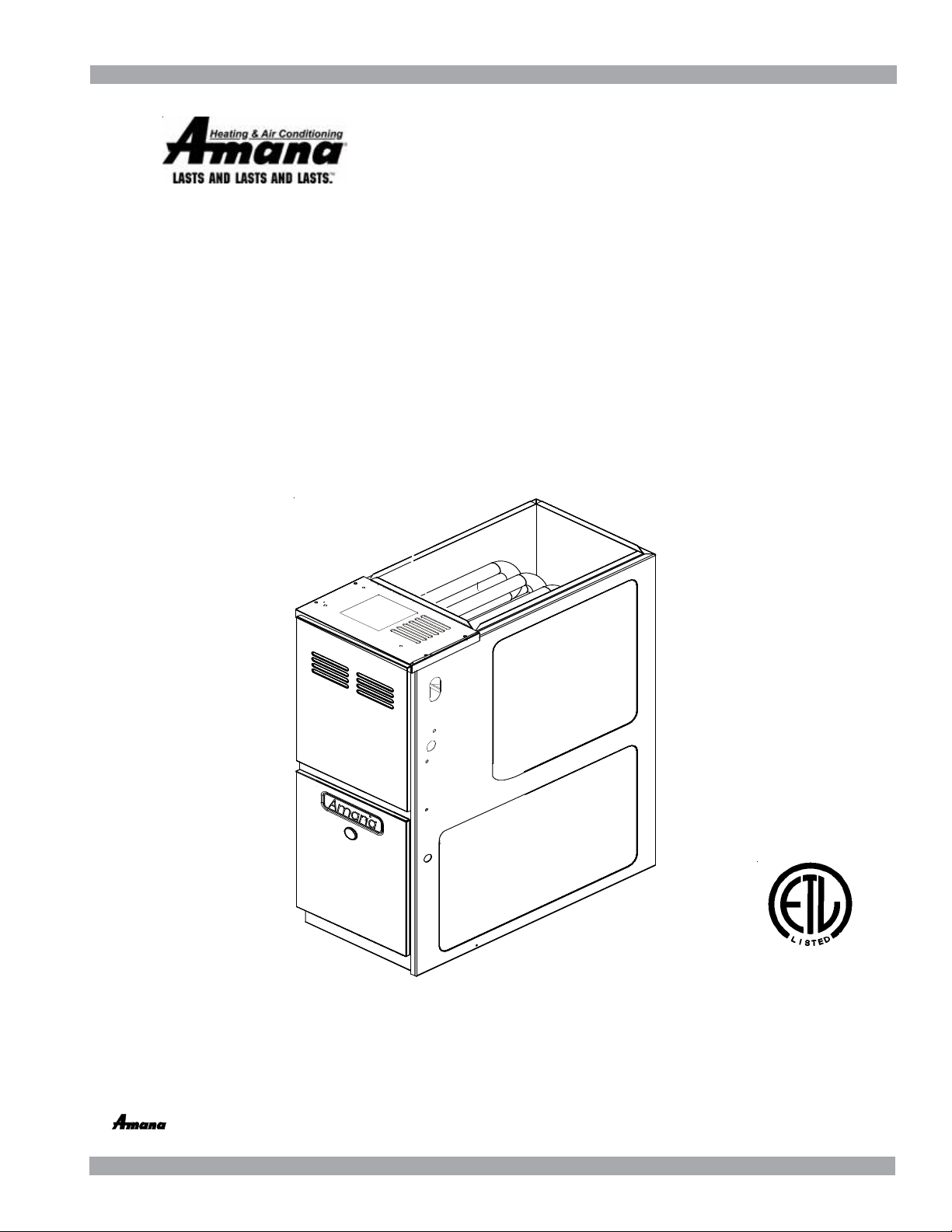
AMH8 33-3/8" 80% Gas Furnace
80% AFUE, T win Comfort™,
Multi-Speed, Upflow/Horizontal (NOx)
• Refer to Service Manual RS6610004 for installation, operation, and troubleshooting information.
• All safety information must be followed as provided in the Service Manual.
• Refer to the appropriate Parts Catalog for part number information.
• Model numbers listed on page 3.
®
C
This manual is to be used by qualified, professionally trained HVAC technicians only.
Goodman does not assume any responsibility for property damage or personal injury due
to improper service procedures or services performed by an unqualified person.
is a registered trademark of Maytag Corporation or its related companies
and is used under license to Goodman Company, L.P., Houston, TX. All rights reserved.
Copyright ©2009-2010 Goodman Company, L.P.
US
RT6621017r1
April 2010
Page 2
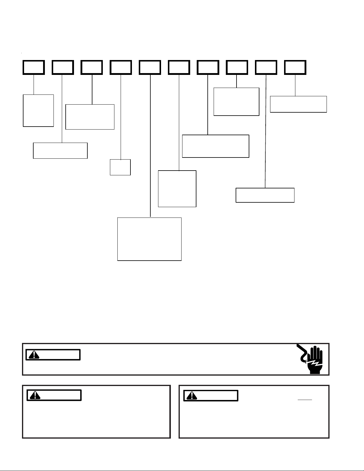
PRODUCT IDENTIFICATION
The model and manufacturing number are used for positive identification of component parts used in manufacturing.
Please use these numbers when requesting service or parts information.
A M H 8 070 3 A X A A
ADDITIONAL
PRODUCT
TYPE:
A: Amana
®
Brand
SUPPLY TYPE:
M: Upflow/Horizontal
FURNA CE TYPE:
H: Twin Comfort
Multi-Speed
TM
AFUE:
8: 80%
CABINET WID TH:
A: 14" C: 21"
B: 17 1/2" D : 24 1/2"
AIRFLOW
CAPABILITY:
3: 1200
4: 1600
5: 2000
FEATURES:
N: Natural Gas
X: Low NOx
MAJOR REVISI ON:
A: Initial Release
MINOR REVISION:
A: Init i al Re leas e
N OMINAL CAPA CITY
045: 45,000 BT UH
070: 70,000 BT UH
090: 90,000 BT UH
11 5: 115,000 BTUH
14 0: 140,000 BTUH
HIGH VOLTAGE!
WARNING
WARNING
WARNING
WARNING
arising from improper service or service procedures. If
you install or perform service on this unit, you assume
responsibility for any personal injury or property damage
which may result. Many jurisdictions require a license to
install or service heating and air conditioning equipment.
Disconnect ALL power before servicing or installing this unit. Multiple power
sources may be present. Failure to do so may cause property damage, personal
injury or death.
Goodman will not be responsible
for any injury or property damage
WARNING
WARNING
ments of an "entry level technician", at a minimum, as
specified by the Air-Conditioning, Heating, and Refrigeration Institute (AHRI). Attempting to install or repair this
unit without such background may result in product
damage, personal injury or death.
Installation and repair of this unit
should be performed
individuals meeting the require-
ONLY by
2
Page 3
PRODUCT IDENTIFICATION
The model and manufacturing number are used for positive identification of component parts used in manufacturing.
Please use these numbers when requesting service or parts information.
AMH80453AXC*
AMH80703AXC*
AMH80704BXC*
AMH80903BXC*
AMH80904BXC*
AMH80905CXC*
AMH81155CXC*
AMH81405DXC*
* Indicates minor revision & is not used for order entry or inventory management
WARNING
WARNING
WARNING
WARNING
Serious property damage, personal injury, reduced unit
performance and/or hazardous conditions may result
from the use of such non-approved devices.
The United States Environmental Protection Agency (“EPA”) has issued various regulations regarding the introduction and disposal of refrigerants introduced into this unit. Failure to follow
these regulations may harm the environment and can lead to the imposition of substantial fines.
These regulations may vary by jurisdiction. Should questions arise, contact your local EPA office.
Do not connect or use any device
that is not design certified by
Goodman for use with this unit.
WARNING
WARNING
do not store combustible materials or use gasoline or
other flammable liquids or vapors in the vicinity of this
appliance.
To prevent the risk of property
damage, personal injury, or death,
3
Page 4

PRODUCT DESIGN
General Operation
The AMH8 furnaces are equipped with an electronic ignition
device used to light the burners and an induced draft blower
to exhaust combustion products.
An interlock switch prevents furnace operation if the blower
door is not in place. Keep the blower access door in place
except for inspection and maintenance.
This furnace is also equipped with a self-diagnosing electronic control module. In the event a furnace component is
not operating properly, the control module LED will flash on
and off in a factory-programmed sequence, depending on
the problem encountered. This light can be viewed through
the observation window in the blower access door. Refer to
the Troubleshooting Chart for further explanation of the LED
codes and Abnormal Operation - Integrated Ignition Control
section in the Service Instructions for an explanation of the
possible problem.
The rated heating capacity of the furnace should be greater
than or equal to the total heat loss of the area to be heated.
The total heat loss should be calculated by an approved
method or in accordance with “ASHRAE Guide” or “Manual
J-Load Calculations” published by the Air Conditioning Contractors of America.
*Obtain from: American National Standards Institute 1430
Broadway New York, NY 10018
Location Considerations
• The furnace should be as centralized as is practical
with respect to the air distribution system.
• Do not install the furnace directly on carpeting, tile, or
combustible material other than wood flooring.
• When suspending the furnace from rafters or joists,
use 3/8" threaded rod and 2” x 2” x 3/8” angle as
shown in the Installation and Service Instructions. The
length of the rod will depend on the application and
clearance necessary.
• When installed in a residential garage, the furnace
must be positioned so the burners and ignition source
are located not less than 18 inches (457 mm) above
the floor and protected from physical damage by vehicles.
WARNING
O PREVENT POSSI BLE PERSONAL INJURY OR DEATH DUE TO ASPHYX I AT I ON,
T
THI S FURNACE MUST BE
CATEGORY III VE NT I NG.
1. Category I Venting is venting at a non-positive pressure.
A furnace vented as Category I is considered a fan-assisted appliance and the vent system does not have to
be “gas tight.” NOTE: Single stage gas furnaces with
induced draft blowers draw products of combustion
through a heat exchanger allowing, in some instances,
common venting with natural draft appliances (i.e. water
heaters). All installations must be vented in accordance
with National Fuel Gas Code NFPA 54/ANSI Z223.1 latest edition. In Canada, the furnaces must be vented in
accordance with the National Standard of Canada, CAN/
CSA B149.1 and CAN/CSA B149.2 - latest editions and
amendments.
NOTE: The vertical height of the Category I venting system
must be at least as great as the horizontal length of the
venting system.
2. Line voltage wiring can enter through the right or left side
of the furnace. Low voltage wiring can enter through the
right or left side of furnace.
3. Conversion kits for propane gas and high altitude natural
and propane gas operation are available. See High Altitude Derate chart for details.
ATEGORY I VENTED . DO NOT VENT USING
C
4
Page 5
PRODUCT DESIGN
Accessibility Clearances (Minimum)
Unobstructed front clearance of 24" for servicing is recommended.
MINIMUM CLEARANCE TO COMBUSTIBLE MATERIALS - INCHES
Sides TopRear Front*
103611
* 24" clearance for serviceability recommended.
** Single Wall Vent (SW) to be used only as a conncetor.
Refer to the venting tables outlined in the Installation Manual for
additional venting requirements.
Vent
SW B
Note: In all cases accessibility clearance shall take precedence over clearances from the enclosure where accessibility clearances are greater. All dimensions are given in
inches.
High Altitude Derate
When this furnace is installed at high altitude, the appropriate High Altitude orifice kit must be installed. This is required due to the natural reduction in the density of both the
gas fuel and combustion air as altitude increases. The kit
will provide the proper design certified input rate within the
specified altitude range.
INPUT PER BURNER - 22,500 BTUH NATURAL GAS / 20,000 BTUH L.P.
ELEVATION ABOVE SEA-LEVEL (FEET)
US BURNER
ORIFICE
CANADA BURNER
ORIFICE
HA-02 HIGH ALTITUDE CONVERSION KIT REQUIRED
Tabled data is based upon the furnace input being reduced for altitudes above sea level. U.S. 4% per 1,000 feet.
Canada 10% derate for 2,000-4,000 feet.
2000 3000 4000 4500 5000 6000 7000 8000
44/55 44/55 45/56 45/56 46/57 47/58 47/58
44/55 47/57
High altitude kits are purchased according to the installation altitude and usage of either natural or propane gas. Refer
to the chart above for a tabular listing of appropriate altitude
ranges and corresponding manufacturer’s high altitude Natural Gas and Propane Gas kits. For a tabular listing of appropriate altitude ranges and corresponding manufacturer's High
Altitude Pressure Switch kits, refer to either the Pressure
Switch Trip Points & Usage Chart in this manual or the Accessory Charts in Service Instructions.
5
Page 6
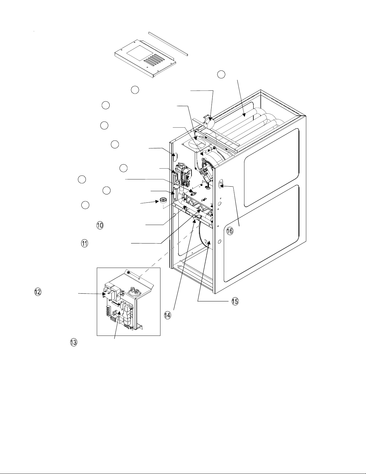
COMPONENT IDENTIFICATION
Pressure Switch
2
3
Flue Pipe Connection
4
Induced Draft Blower
Gas Line
5
Entrance
6
Gas Valve
7
Rollout Limit
8
Junction Box
Tubular Heat Exchanger
1
躀
Transformer
Wiring Harness
9
Grommet
Gas Manifold
Inshot Burner
Integrated Control Module
Upflow/Horizontal
1 Tubular Heat Exchanger
2 Pressure Switch
3 Flue Pipe Connection
4 Induced Draft Blower
5 Gas Line Entrance
6 Gas Valve
7 Rollout Limit
8 Junction Box
Gas Line Entrance
(Alternate)
Circulator Blower
Blower Door
Interlock Switch
Note: Primary Limit Not Shown
9 Wiring Harness Grommet
10 Gas Manifold
11 Inshot Burner
12 Transformer
13 Integrated Control Module
14 Blower Door Interlock Swtich
15 Circulator Blower
16 Gas Line Entrance (Alternate)
6
Page 7

PRODUCT DIMENSIONS
Alt. Gas Inlet
AMH8
Alt. Gas Inlet
High Voltage Inlet
Low Voltage
MODELS A B
AMH80453AX**
AMH80703AX**
AMH80704BX**
AMH80903BX**
AMH80904BX**
14 12-1/2
17-1/2 16
Alt. High Voltag e
Alt. LowVoltage
AMH80905CX**
AMH81155CX**
AMH81405DX** 24-1/2 23
All dimensions are in inches.
21 19-1/2
7
Page 8

PRODUCT DESIGN
PRESSURE SWITCH TRIP POINTS
MODEL
AMH80453AX**
AMH80703AX**
AMH80704BX**
AMH80903BX**
AMH80904BX**
AMH80905CX**
AMH81155CX**
AMH81405DX**
PRESSURE SWITCH TRIP POINTS
AND USAGE CHART
AND USAGE CHART
SQUARE NOSE ROUND NOSE
TRIP POINT
ID BLOWER
PRESSURE
SWITCH
-0.60 B1370142
-0.60 B1370142
-0.60 B1370142
-0.60 B1370142
-0.60 B1370142
-0.70 B1370158
-0.70 B1370158
-0.75 013070159
For installaions in Canada, the AMH8 furnace is certified only to 4,500 ft.
* Negative pressure readings are in inches of water column (*w.c.)
ID BLOWER
PRESSURE
SWITCH
PART #
MODEL
AMH80453AX**
AMH80703AX**
AMH80704BX**
AMH80903BX**
AMH80904BX**
AMH80905CX**
AMH81155CX**
AMH81405DX**
TRIP POINT
ID BLOWER
PRESSURE
SWITCH
-0.60 B1370142
-0.60 B1370142
-0.47 B1370176
-0.75 B1370179
-0.75 B1370179
-0.60 B1370142
-0.70 B1370158
-0.60 013070142
ID BLOWER
PRESSURE
SWITCH
PART #
PRIMARY LIMIT
Part Nu mber 0130F000 35 20162906 20162903 0130F00036
Open Setting (°F)
AMH804 53A*
AMH807 03A*
A MH80704B*
A MH80903B*
A MH80904B*
A MH80905C*
A MH81155C*
A MH81405D*
ROLLOUT LIMIT S WITCHES
Part Number 10123529
Op en Setting (°F)
AM H80453AX**
AM H80703AX**
AM H80704BX**
AM H80903BX**
AM H80904BX**
AM H80905CX**
AM H81155CX**
AM H81405DX**
220 170 160 180
1 --- --- ---
--- 1 --- ---
--- 1 --- ---
--- 1 --- ---
--- --- 1 ---
--- --- --- 1
--- --- --- 1
--- --- 1 ---
AUXIL IARY LIMIT SWITCHES
Part Number 0130F00038
300
2
2
2
2
2
2
2
2
Op en S etting (°F)
AMH80453A*
AMH80703A*
AMH80704B*
AMH80903B*
AMH80904B*
AMH80905C*
AMH81155C*
AMH81405D*
120
1
1
1
1
1
1
1
1
8
Page 9

PRODUCT DESIGN
Coil Matches:
A large array of Amana® brand coils are available for use with the AMH8 furnaces, in either upflow or horizontal applications. These coils are available in both cased and uncased models (with the option of a field installed TXV expansion
device). These 80% furnaces match up with the existing Amana® brand coils as shown in the chart below.
Coil Matches (Amana® brand units using R22 and R-410A):
C A P F 1824 A 6 A
PROD UCT
TYPE:
C: Indoor Coil
APPLICATION
A: Up fl ow/Downfl ow Coil
H: Horizontal A Coil
S: Ho riz ontal Sl ab Coil
EXPANSION
DEVICE:
F: Flowrater
CAB INET FI NIS H:
U: Unpai n ted
P: Painted
N: Unpaint ed Case
REVISION
A : Revision
REFRIGERANT
CHARGE:
6 : R- 4 10A or R- 22
2: R - 22
4: R - 410a
NOM IN AL WIDTH FOR GAS F URNACE
A: Fits 14 " F ur nace Cabine t
B: Fits 17 1/2" Furnace Cabinet
C: Fits 21" Furnace Cabinet
D: Fits 24 1/2" Furnace C abinet
N : Do es Not A pply (Hori z onta l S lab Coils)
NOMINAL CAPACITY RANGE
@ 1 3 SEER
18 24: 1 1/2 to 2 T ons
30 30: 2 1/2 Tons
36 36: 3 Ton s
3642: 3 to 3 1/2 Tons
4860: 4 & 5 Tons
• All CAPF coils in B, C, & D widths have insulated blank off plates for use with one size smaller furnaces.
• All CAPF coils have a CAUF equivalent.
• All CHPF coils in B, C & D heights have an insulated Z bracket for use with one size smaller furnace.
• All proper coil combinations are subject to being ARI rated with a matched outdoor unit.
9
Page 10

PRODUCT DESIGN
Thermostats:
The following Amana® brand Thermostats are suggested for use with the AMH8 Furnace Models:
THERMOSTATS
Thermostat Mech./Digital Programmable Cool Heat
CHT-18-60 Mechanical Yes Yes Yes
CH70TG Digital No Yes Yes
CHSATG Mechanical Yes Yes Yes
H20TWR Mechanical Yes No Yes
Filters:
Filters are required with this furnace and must be provided by the installer. The filters used must comply with UL900 or
CAN/ULCS111 standards. Installing this furnace without filters will void the unit warranty.
Upflow Filters
Side Return(s) Bottom Return
Cabinet
Width
(in.)
Nominal
Filter Size
(in.)
Approx.
Flow Area
2
)
(in
Cabinet
Width
(in.)
Nominal
Filter Size
(in.)
All 16 x 25 x 1 400 14 12 x 25 x 1 300
17-1/2 14 x 25 x 1 350
21 16 x 25 x 1 400
24-1/2 20 x 25 x 1 500
Approx.
Flow Area
2
)
(in
Refer to Minimum Filter Area tables to determine filter area requirement. NOTE: Filters can also be installed elsewhere in
the duct system such as a central return.
MINIMUM FILTER SIZES
FURNACE INPUT FILTER SIZE TYPE
45M
70M
90M
115M
140M
45M
70M
90M
115M
140M
PERMANENT NOMINAL 600 F.M. FACE VELOCITY
DISPOSABLE NOMINAL 300 F.M. FACE VELOCITY
160 in
241 in
320 in
400 in
370 in
320 in
483 in
640 in
800 in
738 in
2
2
2
2
2
2
2
2
2
2
permanent
permanent
permanent
permanent
permanent
disposable
disposable
disposable
disposable
disposable
10
Page 11

PRODUCT DESIGN
TwinComfort™ Configuration & Operation
TwinComfort™
This furnace is capable of the following heating modes:
• Single Stage (Factory Setting)
• Modified Two-Stage
> Fixed 5-Min. Low Stage
> Auto Time (1-12 Min.) Low Stage
To change from the factory single-stage operation,
adjust the dipswitches on the ignition control as follows:
OFF ON
MODE
5 MIN. FIXED
AUTO
Note: This furnace is designed to be used
with a single-stage room thermosat.
Start Start
Call for Heat Call for Heat
Safety Circuit Check Safety Circuit Check
Start Furnace
in Low Stage
Low-Heat Blower Low-Heat Blower
Delay Time (5 Min) Delay Time 1-12 Min)
Gas Valve Switch
to 2nd Stage
Blower Switch to
Hi Heat Operation
MODE DIP SWITCH
2ND STAGE DELAY
DIPSWITCH
Start Furnace
in Low Stage
Gas Valve Switch
to 2nd Stage
Blower Switch to
Hi Heat Operation
T-Stat Satisfied T-Stat Satisfied
11
Page 12

FURNACE SPECIFICATIONS
(
)
(
)
MODEL
AMH80453AX**
Input, Natural Gas (BTUH) 45,000 70,000 70,000 90,000 90,000 90,000 115,000 140,000
Output, Natural Gas (BTUH)
Out pu t , LP ( BT UH) 32, 0 00 48,000 48,000 64,0 00 6 4,000 64,0 00 80,000 96,0 00
A.F.U. E. 80.0 % 8 0. 0% 80.0% 80.0% 80.0% 80.0% 80. 0% 80.0%
Rated External Static (" w.c.) 0.20 - 0.50 0.20 - 0.50 0.20 - 0.50 0.20 - 0.50 0.20 - 0.50 0.20 - 0.50 0.20 - 0.50 0.20 - 0.50
Temperature Rise (°F) 25 - 55 25 -55 20 - 50 35 - 65 35 - 65 35 - 65 35 - 65 40 - 70
Pres s u re Switc h Tr ip Poin t (" w.c.) -0.70 -0.70 -0 .75 -0.7 5 -0. 75 -0 .7 5 -0.90 -0 .80
Blower W heel (D" x W ") 10x6 10x6 10x8 10x8 10x8 10x10 10x10 11x10
Blower H orsepower 1/3 1/3 1 /2 1/3 1/ 2 1/2 1/2 3/4
Blower Speeds 4 4 4 4 4 4 4 4
Max CFM @ 0.5 E.S.P . 128 0 1100 1610 1439 1738 1854 1902 2084
Power Supply ( Volts/Hz/Ph) 115/60/1 115/60/1 115/60/1 115/60/1 115/60/1 115/60/1 115/60/1 115/60/1
Minimum Circuit Ampacity (MCA)
Maximum Overcurrent Device
Transformer (VA) 40 40 40 40 40 40 40 40
Pr i m ary Limit S ettin g (° F) 220 17 0 1 7 0 17 0 160 180 180 1 60
Aux i l ia ry Lim it Sett i ng (°F) 120 120 120 1 20 12 0 120 12 0 120
Rollout Li m it Setting (°F) 300 300 300 300 300 300 300 300
Fa n Dela y On Heat i ng 30 30 3 0 30 30 3 0 30 3 0
Off Heating * 150 150 150 150 150 150 150 150
Fa n Dela y On Cooli ng 5 5 5 5 5 5 5 5
Off Cooling 45 45 45 45 45 45 45 45
Fan Delay On - Fan Only 0 0 0 0 0 0 0 0
Ga s S u ppl y Pr essu re
Natural/Propane) (" w.c.
Manifold Pressure
Natural/Propane) (" w.c.
Orifice Size (Natural/Propane) 43 / 55 43 / 55 43 / 55 43 / 55 43 / 55 43 / 55 43 / 55 43 / 55
Number of Burners
Vent Connector D ia met er (inc he s) 4 4 4 4 4 4 4 4
Shipping W eight (lbs.) 115 125 136 146 146 154 154 153
1
3
36,000 56,000 56,000 72,000 72,000 72,000 92,000 112,000
2
8.1 8.1 12.5 8.1 12.5 12.5 12.5 14.7
15 15 15 15 15 15 15 15
7 / 11 7 / 11 7 / 11 7 / 11 7 / 11 7 / 11 7 / 11 7 / 11
3.5 / 10 3.5 / 10 3. 5 / 10 3. 5 / 10 3.5 / 1 0 3.5 / 10 3.5 / 10 3 .5 / 10
23344456
AMH80703AX**
AMH80704BX**
AMH80903BX**
AMH80904BX**
AMH80905CX**
AMH81155CX**
AMH81405DX**
*Off Heating - This fan delay timing is adjustable (90, 120, 150 or 180 seconds). 150 seconds as shipped.
1. These furnaces are manufactured for natural gas operation. Optional kits are available for conversion to propane operation.
2. Minimum Circuit Ampacity calculated as: (1.25 x Circulator Blower Amps) + I.D. Blower Amps. Wire sizes should be determined in accordance
with National Electrical Codes.Extensive wire runs will require larger wire sizes.
3 Maximum Overcurrent protections Device refers to maximum recommended fuse or circult breaker size. May use time delay fuses or HACR-
type circuit breakers of the same sizes as noted.
NOTES:
1. For elevations above 2000 feet the rating should be reduced by 4% for each 1000 feet above sea level. The furnace must not be derated,
orifice changes should only be made if necessary for altitude.
2. The total heat loss from the structure as expressed in TOTAL BTU/HR must be calculated by the manufacturers method or in accordance with
the "A.S.H.R.A.E. GUIDE" or "MANUAL J-LOAD CALCULATIONS" published by the AIR CONDITIONING CONTRACTORS OF AMERICA. The total
heat loss calculated should be equal to or less than the heating capacity. Output based on D.O.E. test procedures, steady state efficiency times
output.
12
Page 13

BLOWER PERFORMANCE SPECIFICATIONS
(CFM & Temperature Rise vs. External Static Pressure)
Model
Motor
Heating Speed
()
As Shipped
*M(H/S)80453A*** MED 2.5 1160291160291132291121301082311042997925
(MEDIUM) MED-LO 2.0 961 35 955 35 948 35 932 36 913 37 882 821 803
*M(H/S)80703A*** MED 2.5 109847108148105149103950102151 983924868
(MEDIUM) MED-LO 2.0 919 56 913 57 892 58 847 ---- 829 ---- 818 792 728
*M(H/S)80704B*** MED 3.5 166831166331165631164532161632154914921391
(MEDIUM) MED-LO 3.0 141937142636142636143236141937137813281261
*M(H/S)80903B*** MED 2.5 11595811565811455811275911086010751033957
(MEDIUM) MED-LO 2.0 938 ---- 916 ---- 916 ---- 900 ---- 889 ---- 865 829 785
*M(H/S)80904B*** MED 3.5 173638170839165240161141154043147513941307
(MEDIUM) MED-LO 3.0 149345166840145946142947138948133912741204
*M(H/S)80905C*** MED 4.0 185236182037177738171939164141156714691382
(MEDIUM) MED-LO 3.5 161541159242155643151644147045140513461235
*M(H/S)81155C*** MED 4.0 185846184746179947174449167451157714931399
(MEDIUM) MED-LO 3.5 159653158754157154155255149357139713261217
*M(H/S)81405D*** MED 4.0 157566155867154567151369150069141913541271
(MEDIUM) MED-LO 3.5 1402 ---- 1380 ---- 1343 ---- 1319 ---- 1296 ---- 1245 1183 1106
Speed
HIGH 3.0 152122146623141424137324129826124311641075
LOW 1.5 781 43 785 42 781 43 773 43 761 44 745 716 668
HIGH 3.0 14223613523813074011974311574510921075983
LOW 1.5 758 ---- 741 ---- 741 ---- 733 ---- 699 ---- 677 649 626
HIGH 4.0 2134----210025204225197526188328178617001601
LOW 2.5 1134 46 1145 45 1166 44 1171 44 1160 45 1144 1111 1071
HIGH 3.0 160741157242154743149845144846139013021222
LOW 1.5 785 ---- 766 ---- 743 ---- 730 ---- 709 ---- 683 666 604
HIGH 4.0 2051----1983----189535181237172539162715301439
LOW 2.5 1200 56 1185 56 1180 56 1173 57 1158 58 1125 1125 1080
HIGH 5.0 2290 ---- 2229 ---- 2155 ---- 2047 ---- 1960 ---- 1837 1712 1584
LOW 3.0 1290 52 1285 52 1265 53 1235 54 1214 55 1174 1044 904
HIGH 5.0 232337222538212040204042197443180116881577
LOW 3.0 1291 ---- 1272 ---- 1261 ---- 1257 ---- 1205 ---- 1168 1118 1060
HIGH 5.0 246942238943230045222347213149202719021786
LOW 3.0 1200 ---- 1186 ---- 1161 ---- 1127 ---- 1082 ---- 1042 995 926
Tons AC
a t 0.5" 0.6 0.7 0 .8
ESP CFM RISE CFM RISE CFM RISE CFM RISE CFM RISE CFM CFM CFM
EXTERNAL STATIC PRESSURE (Inches Water Column)
0.1 0.2 0.3 0.4 0.5
NOTES:
1. CFM in chart is without filters(s). Filters do not ship with this furnace, but must be provided by the installer.
2. All furnaces ship as high speed cooling. Installer must adjust blower cooling speed as needed.
3. For most jobs, about 400 CFM per ton when cooling is desirable.
4. INSTALLATION IS TO BE ADJUSTED TO OBTAIN TEMPERATURE RISE WITHIN THE RANGE SPECIFIED ON THE RATING PLATE.
5. The chart is for information only. For satisfactory operation, external static pressure must not exceed value shown on rating plate. The shaded area indicates
ranges in excess of maximum external static pressure allowed when heating. The data for 0.6" w.c. to 0.8" w.c. is shown for air conditioning purposes only.
6 The dashed (---) areas indicate a temperature rise not recommended for this model.
7. The above chart is for U.S. furnaces installed at 0-2000 feet. At higher altitudes, a properly derated unit will have approximately the same temperature rise at a
particular CFM, while the ESP at that CFM will be lower.
13
Page 14

BLOWER PERFORMANCE SPECIFICATIONS
MPER
RE R
÷ CFM
130 140 150
900
FORMULAS
BTU OUTPUT = CFM x 1.08 x RISE
1.08
BTU OUTPUT
RISE =
100
2400 CFM
2200
2000
1800
1600
1400
1200
1100
1000
OUTPUT BTU/HR x 1000
14
800
BTU OUTPUT vs TEMPER ATURE RISE CHART
600 CFM
700
30 40 50 60 70 80 90 110 120
100
90
80
70
60
ISE
50
ATU
TE
40
30
20
10
Page 15

WIRING DIAGRAMS
A
)
)
)
)
)
)
)
)
(3)
)
A
WARNING:DISCONNECT POWER BEFORE
SERVICING.WIRING TO UNIT MUST BE
PROP ERLY POLARIZ ED AND GR OU N D ED .
24 VAC
HUMIDIFIER
CGRWY
78
654
321
RD
RD
PU
YL
YL
PU
HIGH VOLTAGE!
DISCONNECT ALL POWER BEFORE SERVICING OR INSTALLING THIS
UNIT. MULTIPLE POWER SOURCES MAY BE PRESENT . FAILURE TO
DO SO MAY CAUSE PROPERTY DAMAGE, PERSONAL INJURY OR DEATH.
0
1
2
3
4
5
6
7
8
C
COLOR CODES:
YL YELLOW
OR ORANGE
PU PURPLE
GR GREEN
BK BLACK
WH
BK
WH
WH
WH
HOT
SURFACE
IGNITER
PU
STEADY ON = NORMAL OPERATION
OFF = CONTRO L F AILURE
1 FLASH =
2 FLASHES = PRESSURE SWITCH STUCK CLOSED
3 FLASHES = PRESSURE SWITCH STUCK OPEN
4 FLASHES = OPEN HIGH LIMIT
5 FLASHES = FLAME SENSE WITHOUT GAS VAL VE
6 FLASH ES =
7 FLASHES = LOW FLAME SIGNAL
8 FLASHES = CHECK IGNITER OR IMPROPE R GROUND
RAPID FLASHES = REVERSED 115 VAC POLARITY/VERIFY GND
2
1
BK
WH
GR
SWITCH LOCATED IN BLOWER
COMP ARTMENT ON SOME MODELS
RD
RD
PM1HIC
PU
(SINGLE CONTROL ON SOM E M ODEL S)
SYSTEM LOCKOUT (RETRIES/RECYCLES EXCEEDED)
OPEN ROLLOUT OR OPEN FUSE
PK PINK
BR BROWN
WH WHITE
BL BLUE
GY GRAY
RD RED
HUMIDIFIER
XFMR (6)
GND (8
MVC (9
MVH (12)
O
(
F
1
I
N
R
E
S
E
XFMR
XFMR-H
LINE-H
DOOR
SWITCH
1
O
2
4
I
E
)
V
5
E
L
D
T
C
M
T
C
T
R
M
R
TO
MICRO
FP
1
5
V
)
V
L
D
I
I
N
O
I
E
O
EAC-H
V
E
O
A
N
C
S
IGN
IND
A
R
LINE-N
GND
LINE H
N
L
E
T
C
C
N
A
MVL (2
PS (10
PSO (4
HLI (7
HLO (1
RO2 (11
RO1 (5
1
/
R
U
,
T
T
I
HOT SURFACE
ELECTRONIC
IR CLEANER
Ø
E
N
R
E
P
D
U
P
N
L GND
/
T
R
T
S
C
24V THERMOSTA T CONNE CTIONS
5 MIN
2 STG
MODE
WH
BL
CICULATOR
BR
BLOWER
BL
WH
15 PIN PLUG
ON SOME MODELS
BLOWER COMPARTMENT
BURNER COM PARTMENT
NO
PRESSURE
YL
SWITCH
BK
BK
W
H
INDUCED DRAFT
BLOWER
FLAME
SENSOR
UXILIARY
LIMITS
BR
OR(MED LOW)
RD (LOW)
WH (N)
CAP
BL (MED)
BK (HI)
24 VAC
HUMIDIFIER
C
WH
INTEGRATED
CONTRO L MODUL E
BL
RD
BK
PRIMARY LIMIT
YL
32
2 STAGE
GAS VAL VE
ROLLOUT LIMITS
BR
OR
24V
115V
XFMR
DOOR SWITCH
YL
BR
PU
PARK
BK
RD
OR
BL
WH
L
L
H
INTERNAL TO
INTEGRATED CONTROL
NOTES:
1. SET HEAT ANTICIPATOR ON ROOM THERMOSTAT A T 0.7 AMPS.
2. MANUFACTURER'S SPECIFIED REPLACEMENT PARTS MUST BE USED WHEN SERVICING.
3. IF ANY OF THE ORIGINAL WIRE AS SUPPLIED WITH THE FURNACE MUST BE
REPLACED, IT MUST BE REPLACED WITH WIRING MATERIAL HAVING A TEMPERATURE
RATING OF AT LEAST 105
4. BLOWER SPEEDS SHOULD BE ADJUSTED BY INSTALLER TO MATCH THE INSTALLA TION
REQUIREMENTS SO AS TO PROVIDE THE CORRECT HEATING TEMPERATURE RISE AND THE
CORRECT COOLING CFM. (SEE SPEC SHEET FOR AIR FLOW CHART)
5. UNIT MUST BE PERMANENTLY GROUNDED AND CONFORM TO N.E.C. AND LOCAL CODES.
O
T
6
.
O
F
H
T
A
L
C
L
E
R
O
A
E
H
T
R
M
R
°C. USE COPPER CONDUCTORS ONLY.
L
E
A
S
T
5
F
A
2
N
S
E
D
C
N
O
T
S
M
L
U
O
T
,
S
I
S
L
H
W
E
I
N
E
R
S
T
G
Y
W
R
INTEGRATED CONTROL MODULE
BR
BR
YL
JUNCTION
BOX
TO 115 VAC/ 1/60HZ
POWER SUPPLY WITH
OVERCURRENT PROTECTION
DEVICE
L
G
W
T
A
V
O
O
W
O
V
O
L
T
G
A
I
E
L
A
T
G
O
V
I
H
E
L
A
T
G
V
O
N
O
P
C
L
G
U
T
T
N
E
L
E
O
C
T
O
(
N
B
Y
D
A
N
T
E
E
1
(
F
J
U
E
T
N
A
H
AMH8_CA/CB
INTEGRATED
CONTROL MODULE
GND
C2
GAS
VALVE
HI
M1
ID BLOWER
PRESSURE
SWITCH
NO
C
24 VAC
40 VA
TRANSFORMER
115 VAC
FLAME SENSOR
IGNITER
ID
BLWR
CIRCULATOR
BLWR
JUNCTION BOX
Z
H
P
6
0
T
E
O
R
P
E
Q
F
W
S
W
I
S
T
P
S
S
W
S
E
.
)
XFMR-N
IGN-N
IND-N
CIR-N
EAC-N
LINE-N
DISCONNECT
N
E
R
P
W
P
O
S
U
T
N
O
C
I
I
E
V
D
I
U
M
P
T
E
N
G
N
F
G
I
E
L
D
P
L
S
E
I
C
I
E
L
D
I
T
H
(
C
T
E
P
.
M
I
T
N
I
G
S
S
.
E
P
R
(
H
C
E
R
R
U
C
E
R
V
O
.
T
O
R
C
E
V
I
D
INTEGRATE D CONTROL MODULE
L
Y
W
T
I
H
E
C
D
N
D
)
E
R
)
T
N
E
H
I
C
T
Wiring is subject to change. Always refer to the wiring diagram on the unit for the most up-to-date wiring.
15
Page 16

WIRING DIAGRAMS
AMH8_CC
WARNING:DISCONNECT POWER BEFORE
SERVICING.WIRING TO UNIT MUST BE
PROPERLY POLARIZED AND GROUNDED.
24 VAC
HUMIDIFIER
C
CGRWY
1110
12
978
654
321
CONTROL MODULE
RD
RD
PU
YL
YL
PU
WH
BK
WH
WH
WH
RD
LINE NEUTRAL
2
1
BK
WH
GR
SWITCH LOCATED IN BLOWER
COMPARTMENT ON SOME MODELS
RD
RD
PM1HIC
HOT
SURFACE
IGNITER
HIGH VOLTAGE!
DISCONNECT ALL POWER BEFORE SERVICING OR INSTALLING THIS
UNIT. MULTIPLE POWER SOURCES MAY BE PRESENT . FAILURE TO
DO SO MAY CAUSE PROPERTY DAMAGE, PERSONAL INJURY OR DEAT H.
0
STEADY ON = NORMAL OPERATION
1
2
3
4
5
6
7
8
C
COLOR CODES:
YL YELLOW
OR ORANGE
PU PURPLE
GR GREEN
BK BLACK
PU
OFF = CONTROL FAI LURE
1 FLASH =
2 FLASHES = PRESSURE SWITCH STUCK CLOSED
3 FLASHES = PRESSURE SWITCH STUCK OPEN
4 FLASHES = OPEN HIGH LIMIT
5 FLASHES = FLAME SENSE WITHOUT GAS VALVE
6 FLASHES =
OPEN ROLLOUT OR OPEN FUSE
7 FLASHES = LOW FLAME SIGNAL
8 FLASHES = CHECK IGNITER OR IMPROPER GROUND
RAPID FLASHES = REVE RSED 115 VAC POLARITY/VERIFY GND
2 STAGE
GAS VALVE
(HONEY WELL)
PU
ROLLOUT LIMITS
(SINGLE CONTROL ON SOME MODELS)
SYSTEM LOCKOUT (RETRIES/RECYCLES EXCEEDED)
PK PINK
BR BROWN
WH WHITE
BL BLUE
GY GRAY
RD RED
0140F00 662 REV. A
5 MIN
AUTO
2 STG
1 STG
100 SE C
150 SE C
FUSE
SEE NOTE 6
INTEGRATED
FS
BL
OR
EAC-HLINE-HXFMR-H
24V
115V
XFMR
BK
DOOR SWITCH
PRIMARY LIMIT
YL
YL
BR
23
PU
NOTES:
1. SET HEAT ANTICIPATOR ON ROOM THERMOSTAT AT 0.7 AMPS.
2. M ANUFACTURER'S SPECIFIED REPLACEMENT PA RTS MUST BE USED WHEN SERVICING.
3. IF ANY OF THE ORIGINAL WIRE AS SUPPLIED WITH THE FURNACE MUST BE
REPLACED, IT MUST BE REPLACED WITH WIRING MATERIAL HAVING A TEMPERATURE
RATING OF AT LEAST 105
4. BLOWER SPEEDS SHOULD BE ADJUSTED BY INSTALLER TO MATCH THE INSTALLATION
REQUIREMENTS SO AS TO PROVIDE THE CORRECT HEATING TEMPERATURE RISE AND THE
CORRECT COOLING CFM. (SEE SPEC SHEET FOR AIR FLOW CHART)
5. UNI T MUST BE PERMANENTLY GROUNDED AND CONFORM TO N.E.C. AND LOCAL CODES.
6. TO RECALL THE LAST 5 FAULTS, MOST RECENT TO LEAST RECENT, DEPRESS SWITCH
FOR MORE THAN 2 SECONDS WHILE IN STANDBY(NO THERMOSTAT INPUTS).
Y
L
D
G
T
S
D
N
2
MODE
H
T
O
F
F
D
L
Y
WH
BL
DIAG NOST IC
LED
BR
BL
WH
15 PIN PLUG
ON SOME MODELS
BLOWER COMPARTMENT
BURNER COMPARTMENT
OR
YL
BK
W
H
INDUCED DRAFT
FLAME
SENSOR
AUXILIARY
LIMITS
BR
WH (N)
CICULATOR
BLOWER
NO
PRESSURE
SWITCH
BK
BLOWER
OR(MED LOW)
RD (LOW)
CAP
HUMIDIFIER
WH
BR
COOL-HHI HEAT-H
LO HEAT-H
PAR K
BK
RD
BL
WH
°C. USE COPPER CONDUCTORS ONLY.
24V THERMOSTAT CONNECTIONS
G
Y
W
R
XFMR-H
INTEGRATED CONTROL MODULE
BL (MED)
BK (HI)
BR
BR
LINE-H
24 VA C
C
WARNING:
DISCONNECT POWER
YL
BEFORE SERVICING.
WIRING TO UNIT
MUST BE
PROPERLY
POLARIZED
AND GROUNDED.
JUNCTION
BOX
TO 115 VA C/ 1/60HZ
POWER SUPPLY WITH
OVERCURRENT PR OTECTION
DEVICE
LOW VOLTAGE (24V)
LOW VOLTAGE FIELD
HI VOLTAGE (115V)
HI VOLTAGE FIELD
JUNCTION
TERMINAL
INTERNAL TO
INTEGRATED C ONTROL
PLUG CONNECTION
TO
MICRO
XFMR (3)
DOOR
SWITCH
OVERCURRENT PROTE CTION DEVICE
HUMIDIFIER
XFMR (6)
GND (8)
MVC (9)
MVH (12)
MVL (2)
AUXILIARY
LIMIT CONTROLS
PS (10)
PSO (4)
HLI (7)
HLO (1)
RO2 (11)
RO1 (5)
MANUAL RESET ROLLOUT
LIMIT CONTROL(S)
(SINGLE CONTROL ON SOME MODELS)
FLAME SENSOR
FP
EAC-H
HOT SURFACE
IGNITER
IGN
ID
H
E
A
COOL-H
I
H
T
A
E
H
ELECTRONIC
AIR CLE ANER
BLWR
L
O
T
-
H
CIRCULATOR
H
-
JUNCTION BOX
IND
LGND
LINE-N
GND
LINE H
24 VA C
115 VAC
BLWR
SWITCH (TEMP.)
SWITCH (PRESS.)
INTEGRATED
CONTROL MODULE
GND
C2
GAS
VALVE
HI
M1
C
40 VA
TRANSFORMER
XFMR-N
IGN-N
IND-N
CIR-N
EAC-N
LINE-N
DISCONNECT
N
EQUIPMENT GND
FIELD GND
FIELD SPLICE
IGNITER
OVERCURRENT
PROT. DEVICE
ID BLOWER
PRESSURE
SWITCH
NO
AUTO RESET
PRIMARY
LIMIT
CONTROL
INTEGRATED CONTROL MODULE
16
Wiring is subject to change. Always refer to the wiring diagram on the unit for the most up-to-date wiring.
Page 17

SCHEMATICS
CIRCUL
BLOWER
ATOR
HIGH VOLTAGE!
DISCONNECT ALL POWER BEFORE SERVICING OR INSTALLING THIS
UNIT. MULTIPLE POWER SOURCES MAY BE PRESENT. FAILURE TO
DO SO MAY CAUSE PROPERTY DAMAGE, PERSONAL INJURY OR DEATH.
ELECTRONIC
AIR CLEANER
NDUCER
I
COOL
K2
K3
FLAME
SENSOR
PROBE
HI
HEAT
K2
K1
.0005
3M
FP
IGN
HEAT
K3
IGN
ITOR
LO
K4
GND
PARK
COM
HI
2-STAGE
GAS V
CIR
NEU
FACTORY
JUMPER
MV MLV
PM
ALVE
EAC
K5
PS
C
EA
NEU
K6
FACTORY
JUMPER
HLO
HIGH
LIMIT
PRESSURE
SWITCH
IND
HLI
AUX
LIMIT
K7
PSO
R
RO2
RO1
TH
XFM
HOT
XFMR
NEU
TR
C
Y
G
W
ROLLOUT
SWITCH
R
24 VAC
COMPRESSOR
TACTOR
CON
COIL
Y
G
W
THERMOSTAT
R
TYPICAL SCHEMATIC
AMH8 ____** MODEL FURNACES
WR 50M56-289 INTEGRATED IGNITION CONTROL
This schematic is for reference only. Not all wiring is as shown above. Always refer to the appropriate wiring diagram for the unit being serviced.
17
 Loading...