

Page 1

Service
Series "D"
Plastic Tub Dishwashers
Models and manufacturing
numbers in this manual
CDU300DB P1307505W
CDU220DB P1307506W
ADU7000DWW P1307507W
ADU7000DBB P1307508W
ADU7000DLL P1307509W
ADU6000DWW P1307510W
ADU6000DB P1307511 W
ADU5000DWW P1307512W
ADU5000DB P1307513W
ADU3000DB P1307514W
ADU3000DWW P1307515W
CDU300DB P1309605W
CDU220DB P1309606B
ADU7000D P1309607W
ADU7000D P1309608B
ADU7000D P1309609L
ADU6000D P1309610W
ADU6000D P1309611B
ADU5000D P1309612W
ADU5000D P1309613B
ADU3000D P1309614W
ADU3000D P1309615B
This manual is to be used by qualified appliance technicians
only. Amana does not assume any responsibility for property
damage or personal injury for improper service procedures
done by an unqualified person.
RS3300002
Revision 0
August 1997
Page 2
!
Important Information
!
!
!
!
Pride and workmanship go into every product to provide our customers with quality products. It is possible,
however, that during its lifetime a product may require service. Products should be serviced only by a
qualified service technician who is familiar with the safety procedures required in the repair and who is
equipped with the proper tools, parts, testing instruments and the appropriate service manual. REVIEW ALL
SERVICE INFORMATION IN THE APPROPRIATE SERVICE MANUAL BEFORE BEGINNING REPAIRS.
To avoid risk of serious injury or death, repairs should not be attempted by an unauthorized personal, dangerous
conditions (such as exposure to electrical shock) may result.
Amana will not be responsible for any injury or property damage from improper service procedures. If preforming
service on your own product, assume responsibility for any personal injury or property damage which may result.
To locate an authorized servicer, please consult your telephone book or the dealer from whom you purchased this
product. For further assistance, please contact:
Important Information
Important Notices for Consumers and Servicers
WARNING
CAUTION
CONSUMER AFFAIRS DEPT. CALL (1-800-843-0304) or
AMANA If no answer call 1-319-622-5511 and ask for
AMANA, IOWA 52204 Consumer Affairs
If outside the United States contact:
AMANA
ATTN: CONSUMER AFFAIRS DEPT.
AMANA, IOWA 52204, USA
Telephone: (319) 622-5511
Facsimile: (319) 622-2180
TELEX: 4330076 AMANA
CABLE: "AMANA", AMANA, IOWA, USA
Recognize Safety Symbols, Words, and Labels
DANGER
DANGER—Immediate hazards which WILL result in severe personal injury or death.
WARNING
WARNING—Hazards or unsafe practices which COULD result in severe personal injury or death.
CAUTION
CAUTION—Hazards or unsafe practices which COULD result in minor personal injury or product or property
damage.
RS3300002 Rev 0 August 1997
Page 3

Contents
Important Information ................................................ 2
Product Information
Models and Features.................................................4
Model Identification ................................................... 4
Service Information ................................................... 4
Mini-Manual Location ................................................4
Features and Specifications ...................................... 5
Installation Instructions
Buit-In Installation Instructions ..................................6
Preparing Cabinet Opening ................................6
Preparing Electrical Wiring .......................................6
Preparing Hot Water Line ..........................................7
Preparing Drain Plumbing .........................................7
Installing Dishwasher ................................................ 7
Use & Care Instructions
Dishwasher-Safe Items .............................................9
Loading Dishwasher ..................................................10
Preparing Dishes ................................................10
Top Rack.............................................................10
Cup Retainer (some models)..............................10
Cup Shelf (some models) ...................................10
Bottom Rack .......................................................10
Cutlery Basket ....................................................10
Automatic Dishwasher Detergent Dispenser .............11
Changing Color Panels .............................................12
Changing Door Panel..........................................12
Changing Access Panel ...................................... 12
Before Calling for Service .........................................12
Dishwasher Operation
Basic Operation.........................................................13
User Operation ..........................................................13
Basic Components ....................................................14
Basic Functions.........................................................14
Fill with Hot Water ..............................................14
Wash Action ........................................................14
Drain ...................................................................15
Dry ......................................................................15
Inlet, Tub, and Thermostat Temperatures .................16
120° Inlet Water Capability ....................................... 16
Water Temperature Boost...................................16
Operating Instructions
CDU220 ..................................................................... 17
CDU300 ..................................................................... 18
ADU3000 ................................................................... 19
ADU5000 ................................................................... 20
ADU6000 ................................................................... 21
ADU7000 ................................................................... 22
Service Information
Water Valve and Inlet System...................................23
Disassembly .......................................................23
Water Valve Operation .......................................23
Float Switch ...............................................................24
Disassembly .......................................................24
Recalibration.......................................................24
Motor/Pump Mechanism and Boots .......................... 25
Motor/Pump Mechanism Check..........................25
Motor/Pump Removal ......................................... 25
Motor/Pump Replacement Parts.........................26
Reassembly ........................................................26
Soft Food Disposer ...................................................26
Disassembly .......................................................26
Drain Solenoid...........................................................27
Racks ........................................................................27
Rotating Upper Shower Arm .....................................27
Spray Arm .................................................................27
Filter System ............................................................. 28
Drain Action ........................................................28
Filter and Drain ...................................................28
Calrod Heater ............................................................28
Sump Cover and Baffle Grid .....................................28
Tub Corner Baffles ....................................................29
Door Gasket Replacement ........................................29
Door Components .....................................................29
Detergent Cup Cover And Latch.........................29
Rinse Agent Injector ...........................................29
Drying Vent .........................................................30
Control Panel Assembly ............................................ 30
Push Button Switches ...............................................30
Servicing Push Button Switch.............................31
Push Button Switch Test............................................31
Switch Contact Chart ................................................31
Snap On Electrical Components Cover ....................32
Timer.........................................................................32
Timer Testing ......................................................32
Latch Interlock Switches ...........................................33
Door Latch.................................................................33
Strike Adjust .......................................................33
Aluminum Trim Panel ...............................................33
Testing ................................................................33
Repair ................................................................. 33
Schematic Diagrams
ADU3000...................................................................34
ADU5000...................................................................36
ADU6000...................................................................38
ADU7000...................................................................40
CDU220..................................................................... 42
CDU300..................................................................... 44
RS3300002 Rev. 0 3 August 1997
Page 4
Product Information
!
!
WARNING
Disconnect power and close water supply valve
before servicing dishwasher. Never energize
electrical power to dishwasher with any panels
removed.
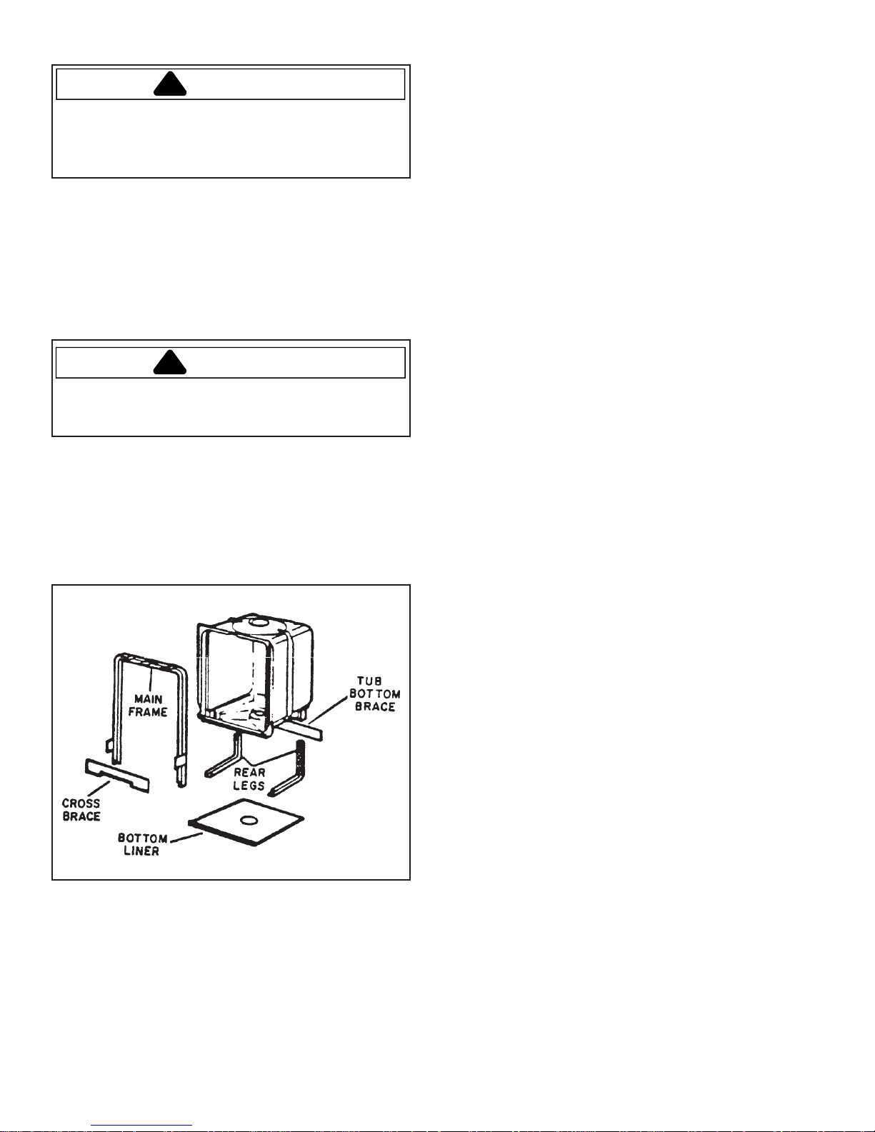
Models and Features
All dishwasher models use one piece of channel steel
as the main frame around tub and the two front legs.
Rear legs are channel steel, and a steel bottom liner
stiffens and supports tub bottom. A cross brace is
used at the front for stiffness. Tub bottom brace
supports the tub when filled with hot water and
prevents deformation.
WARNING
All ground wires removed during servicing must be
reconnected to insure dishwasher is properly
grounded.
Tub is not replaceable. If defective, the entire
dishwasher must be replaced.
The models all have 120°F inlet water capability.
Some models use a water heat thermostat and cycle
extender to extend cycle time for water temperatures
under 140°F. ADU3000, ADU5000, and ADU520 units
use a timed sytem.
Model Identification
Rating label, which gives the model number, is
located on the left side of the tub at the front, and is
visible when the door is opened. This series of models
will have "P" numbers which identify the product.
Service Information
Two different pieces of service literature will be
available. The mini-manual comes with the product.
This piece contains a schematic, cam chart, and
abbreviated service information.
This service manual will contain all pertinent service
reference information including schematics.
Mini-Manual Location
The mini-manual is accessible when the access panel
is removed.
The folded mini-manual is in a 6-inch x 3 1/4-inch
envelope, which is placed between the tub and metal
plate, on the right side.
RS3300002 Rev. 0 4 August 1997
Page 5

Product Information
Features and Specifications
BRAND AMANA CALORI C
MODE L ADU7 000 ADU6000 ADU500 0 ADU3000 CDU520 CDU300 CDU2 20
Colors
White
Black
Gold
Almond
Cup Shelf 2 Meta l 2 Plastic
Silverwa re Basket Super Super X X X X X
Timer
Rotary
Push Buttons
Cycles
Pots and Pans
Heavy Wash
Norma l Wash
Light Wash
China/Crystal
Short Wash
Rinse and Ho ld
Plate Warmer
Options
Delay Start
Heated Dry On
Water Heat Boost
Timer
Calrods Watts 500 500 500 500 500 500 500
Sound SofSound™ Premium Premium Standard Delux Standard
Washability
Wa sh Levels
Mid Level Wash
Rinse Aid Indicato r
Food Disposal
X
X
X
X
10
X
X
X
X
X
X
X
X
10 hours
X
X
X
3
Tower
X
X
X
X
X
X
X
7
X
X
X
X
X
X
X
6 Hours
X
X
X
3
Tower
X
X
X
X
X
X
5
X
X
X
X
X
X
X
X
3
Tower
X
X
X
X
X
X
2
X
X
X
X
X
X
X
3
Tower
X
X
X
X
X
X
X
X
X
X
6 Hours
X
X
X
3
Tower
X
X
X
2
X
X
X
X
X
X
2
Tower
X
X
X
5
X
X
X
2
Tower
August 1997 5 RS3300002 Rev. 0
Page 6

Installation Instructions
Buit-In Installation Instructions
Preparing Cabinet Opening
Dishwasher is designed to fit into a minimum 34 1/2"
height and 24" width and depth. A minimum of 2" is
required between dishwasher and perpendicular
cabinet or wall. Dishwasher must not be installed more
than 10' from sink for proper drainage.
Note: Complete enclosure is not provided with
dishwasher. Installer must provide top, bottom,
back and side enclosures.
Preparing Electrical Wiring
W ARNING
To avoid electrical shock which can cause severe
personal injury or death, open household circuit
breaker to dishwasher before installing or
servicing dishwasher. After installing or servicing
dishwasher, reconnect power.
Note: Electrical wiring must meet local codes and
ordinances. If wiring does not, contact a
licensed electrician.
1. Cut 1 1/2" maximum hole in cabinet for cable or
power cord. Wiring must enter within shaded area.
2. Connecting Dishwasher
Using Cable Direct Connection
Route cable as shown. Cable must extend a
minimum of 24" from back wall of cabinet.
Using Power Cord
Install a three-prong grounded receptacle
in rear of sink cabinet next to dishwasher.
Do not install receptacle in cabinet opening.
Receptacle must be installed at least 6" but not
more than 18" from cabinet opening.
Note:
Edges of cabinet opening for power cord must be
smooth and rounded. If cabinet is metal, edges of
opening must be covered with a rubber cord protector.
Receptacle
5"
4"
Electrical Wiring
5"
Alternate
Receptacle
4"
6"
3"
RS3300002 Rev. 0 6 August 1997
Page 7

Installation Instructions
Preparing Hot Water Line
Note:
• Plumbing must meet local codes and ordinances. If
plumbing does not, contact a licensed plumber.
• Hot water line must accommodate 3/8" copper
tubing or 1/2" plastic tubing. Manual shut-off in hot
water line is recommended.
1. Cut 1 1/2" hole in cabinet for hot water line. Hot
water line must enter within shaded area.
2. Flush water line to clean out debris.
5"
4"
6"
Hot
2"
5"
4"
Installing Dishwasher
W ARNING
To avoid electrical shock which can cause severe
personal injury or death, open household circuit
breaker to dishwasher before installing or
servicing dishwasher. After installing or servicing
dishwasher, restore power.
CAUTION
To avoid property damage, protect soft vinyl or
other flooring with cardboard, rugs or other
protective material during installation.
CAUTION
To avoid property damage, do not tilt dishwasher
forward.
1. Cut end of drain hose at pre-marked line as
necessary. Do not cut corrugated portion of drain
hose.
Preparing Drain Plumbing
Note:
• Plumbing must meet local codes and ordinances. If
plumbing does not, contact a licensed plumber.
• Edges of cabinet opening for drain hose must be
smooth and rounded. If cabinet is metal, edges of
opening must be covered with a rubber cord
protector.
• An air gap must be used if drain hose is connected
to house plumbing lower than 18" above floor level.
All air gap devices must be capable of passing 3/8"
steel ball to assure minimum drain line stoppages.
1"
3/4"
5/8"
August 1997 7 RS3300002 Rev. 0
Page 8
Installation Instructions
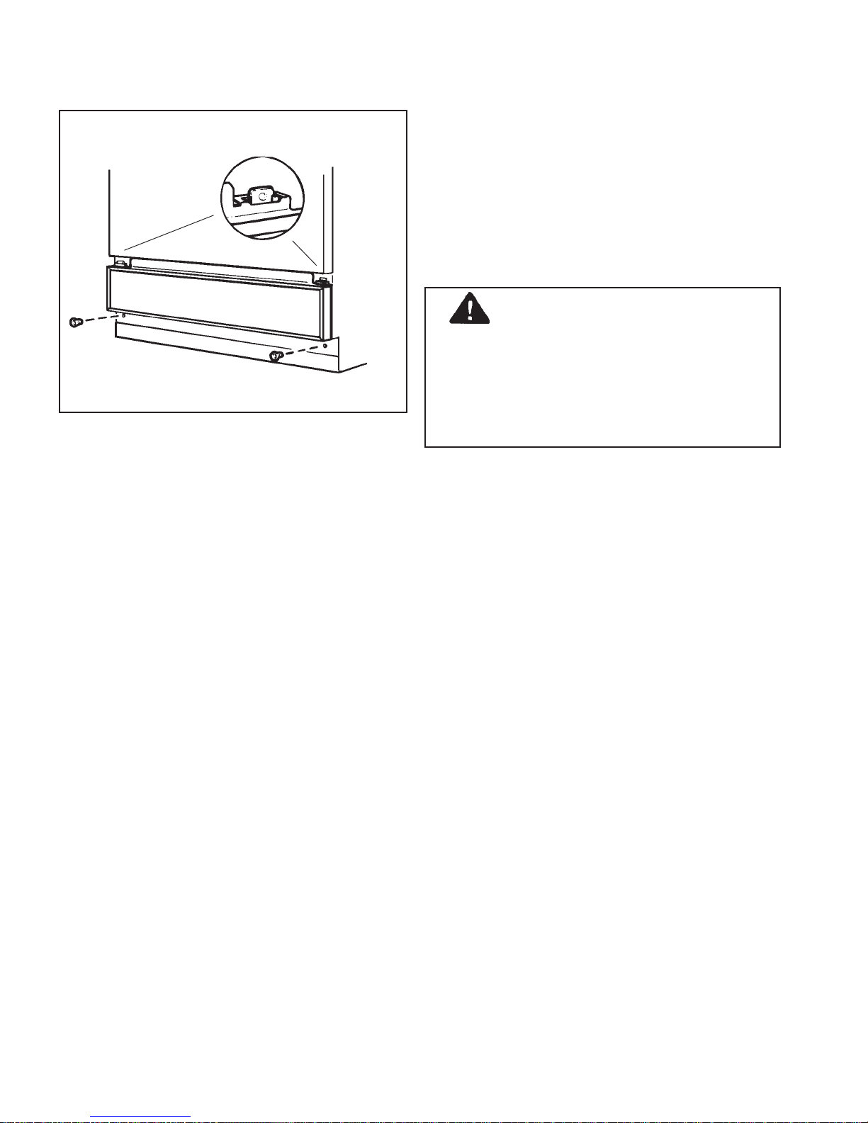
2. Remove access panel by removing screws then
lifting panel up and over tabs.
Tab
3. Confirm drain hose is connected to drain hose
valve.
4. Connect hot water line to water valve using a 90°
elbow. Dishwasher water valve has a 3/8" N.P.S.
internal thread.
5. Remove slotted hex head screws from
wooden base. Lift dishwasher off wooden base.
Discard wooden base and hex head screws.
6. Loosen leveling legs.
7. Push drain hose through opening in cabinet. Route
drain hose through plastic strain relief and connect
to disposer or drain using clamp. If connecting to a
disposer, remove disposer hopper plug before
making connection.
Note: If an air gap is not code required, drain hose
must have a high drain loop, which is 18"
minimum above floor level. This prevents back
flow of water into dishwasher or water siphoning
out during operation.
8. Attach power supply to rear of dishwasher
junction box using a strain relief (not supplied).
Connect wires using wire nuts (not supplied).
Connect incoming black wire to black wire inside
junction box. Connect incoming white wire to white
wire. Connect incoming ground wire to green ground
wire.
DANGER
To avoid electrical shock which can cause severe
personal injury or death, a ground wire must be
provided by installer if house wiring is not twowire with a ground wire. Otherwise dishwasher
will not be grounded. When house wiring is
aluminum, use U.L. approved antioxidant
compound and aluminum-to-copper connectors.
9. Route power cord (if applicable) through opening in
cabinet wall.
10.Slide dishwasher into position. Any excess drain
hose must be coiled under dishwasher.
11.Check front of door for correct vertical alignment. If
dishwasher is not aligned, adjust leveling legs until
dishwasher is aligned with cabinets.
12.Confirm door closes properly and latch engages. If
door strikes cabinets or latch fails to engage, adjust
leveling legs until properly aligned.
Note: Confirm dishwasher is flush with underside of
countertop to reduce sound level.
RS3300002 Rev. 0 8 August 1997
13.Fasten dishwasher to underside of countertop
byinserting screws and tightening. Screws must be
driven straight into countertop to avoid interference
with door.
14.Replace access panel by reversing step 2.
15. Plug power cord (if applicable) into outlet.
16.Pour two quarts of water into dishwasher tub prior to
starting dishwasher for the first time. Water acts as a
lubricant and will prevent possible motor damage.
17.Run dishwasher through a complete cycle to check
for leaks.
Page 9

Use & Care Instructions
Dishwasher-Safe Items
Material Usually Safe Exceptions Special Instructions
Aluminum Yes Some colored anodized aluminum
can fade.
China/Stoneware Yes Antique, metal trimmed,
hand-painted or over-the-glaze
patterns fade. Gold leaf will
discolor.
Crystal Yes Antique, metal trimmed,
hand-painted or over-the-glaze
patterns fade. Gold leaf will
discolor.
Glass Yes Milk glass may yellow.
Iron No
Non-dishware
such as filters,
etc.
Non-stick coatings Yes After washing, wipe non-stick
No Damage to dishwasher and
Some darkening or spotting
possible. Remove by scouring
with soap-filled steel wool pads.
If in doubt, check with
china/stoneware manufacturer or
test wash one piece daily for at
least a month. Compare with rest
of set.
Load securely to prevent
movement. Check crystal
manufacturer's instructions.
discoloration or staining of
dishwasher may result.
coating with vegetable oil to keep
coating from losing non-stick
quality.
Pewter No
Plastics Yes If plast ic does not say
"dishwasher - safe", test one piece
before washing entire set.
Stainless steel Yes Rinse if not washing immediately.
Salty or acid foods can stain if left
on.
Sterling silver and
silver plate
Tin No
Wood No
Yes Contact with stainless steel can
damage silver. Washing with
copper can leave a brown film.
Rinse if not washing immediately.
Salty or acid foods can stain if left
on. Powder detergent can cause
black spots. Avoid placing under
detergent dispe nse r.
August 1997 9 RS3300002 Rev. 0
Page 10
Use & Care Instructions
Loading Dishwasher
Preparing Dishes
Prerinsing of normal food soils is not necessary.
Remove foods such as mustard, mayonnaise, vinegar,
lemon juice that can cause discoloration of stainless
steel.
Caution
To avoid damage to pump, remove solids such as
bones, meat trimmings, rinds, seeds, skins, or
toothpicks.
Top Rack
Top rack is for delicate, plastic or small dishware.
Glasses fit best along the sides. Arrange stemware so
that stemware cannot move easily. Do not let glasses
or stemware touch each other.
Cup Retainer (some models)
Cup retainer secures tall cups and bowls in upper rack.
Cup Shelf (some models)
Cup shelf features a fold down shelf for two levels of
smaller dishware.
Bottom Rack
Bottom rack is best for heavily soiled dishware. Fit
plates and saucers between tines. Load dishware with
soiled side facing center. Prop broiler pans and racks
along edge.
Note: Do not load large dishware in front right corner
of bottom rack. Large dishware prevents
automatic dishwasher detergent from
circulating in wash cycle.
Do not block wash tower or load tall dishware
next to wash tower. Dishware must not
prevent wash tower from rotating freely.
WARNING
To avoid personal injury or property damage, do
not place plastic dishware in dishwasher unless
marked "dishwasher-safe" or equivalent. For
plastic dishware not marked, check
manufacturer's recommendations.
Place sauce pans, mixing bowls and other dishware
face down.
Do not let dishware extend through bottom
rack. This could block wash arm and cause
poor washing results.
Cutlery Basket
Load cutlery basket evenly with dishware mixed. Small
plastic dishware such as measuring spoons and lids
are not recommended for automatic dishwashing. If
placed in dishwasher, these items should be placed in
center compartment.
WARNING
To avoid personal injury or property damage, load
sharp knives so knives do not touch door seal.
Load knives in cutlery basket with handles up.
Note: Take out anything that might fall or extend
through the bottom of basket.
RS3300002 Rev. 0 10 August 1997
Page 11
Use & Care Instructions
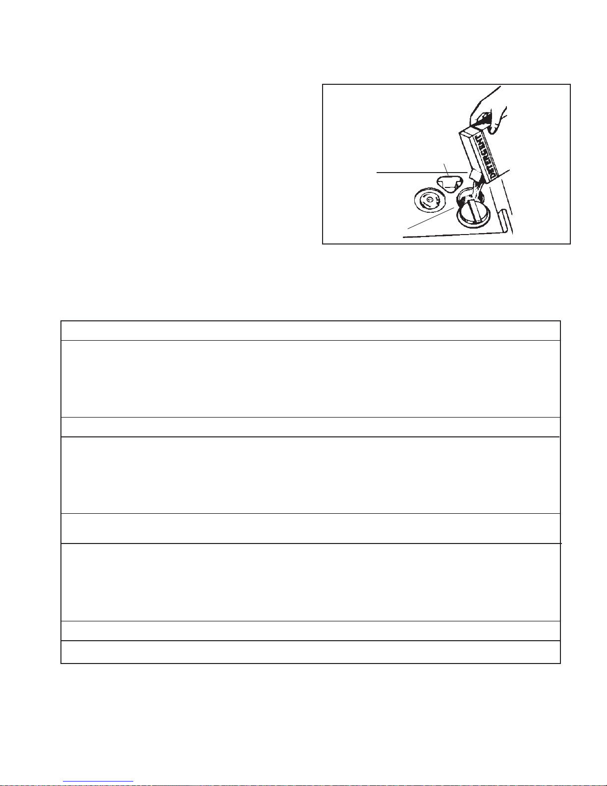
Automatic Dishwasher Detergent
Dispenser
Use main dispenser for all wash programs except
RINSE & HOLD. Reserve dispenser is for two cycle
washes and if extra detergent is necessary.
1. Confirm cycle indicator dial is in
otherwise main dispenser will not close properly.
Add automatic dishwasher detergent.
2. Close main dispenser.
Note: Open main dispenser after dispenser has
been closed by unlatching door and rotating
cycle indicator dial to
dispenser contains automatic dishwasher
detergent, partially open door before rotating
cycle indicator dial. This reduces amount of
spillage into tub.
Automatic Dishwasher Detergent Usage Guide (Cycles vary from model to model)
OFF
position. If
OFF
position,
Reserve Dispenser
Main Dispenser
Soft Water (0-3 Grains per Gallon)
Cycle s Main Dispenser Reserve Di spenser
POTS & PANS 1 Tablespoon minimum 1 Tablespoon minimum
HEAVY, NORMAL or LIGHT WASH 1 Tablespoon minimum 1 Tablespoon minimum
SHORT WASH 1 Tablespoon minimum Optional*
Hard Water (4-10 Grains per Gallon)
Cycle s Main Dispenser Reserve Di spenser
POTS & PANS 1 1/2 Tablespoons minimum 1 Tablespoon minimum
HEAVY, NORMAL or LIGHT WASH 1 1/2 Tablespoons minimum 1 Tablespoon minimum
SHORT WASH 1 1/2 Tablespoons minimum Optional*
Extremely Hard Water
(Over 10 Grains per Gallon)
Cycle s Main Dispenser Reserve Di spenser
POTS & PANS 3 Tablespoons (Full) 2 Tablespoon (Full)
HEAVY, NORMAL or LIGHT WASH 3 Tablespoons (Full) 2 Tablespoon (Full)
SHORT WASH 3 Tablespoons (Full) Optional*
A water softener should be installed if water hardness is over 19 grains per gallon.
*Add automatic dishwasher detergent to reserve dispenser if two wash, three rinse cycle is desired.
August 1997 11 RS3300002 Rev. 0
Page 12
Use & Care Instructions
Changing Color Panels
W ARNING
To avoid electrical shock which can cause severe
personal injury or death, unplug power cord or
open household circuit breaker to dishwasher
before changing panels.
Changing Door Panel
1. Remove door trim from one side of door by
removing screws.
2. Slide out door panel. Turn door panel around and
replace.
3. Replace trim by reversing step 1.
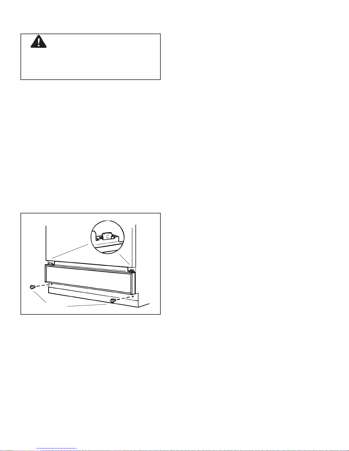
Changing Access Panel
1. Remove access panel by removing screws then
lifting panel up and over tabs.
2. Remove trim by removing screws.
3. Slide out access panel. Turn access panel around
and replace.
4. Replace trim by reversing step 2.
5. Replace access panel by reversing step 1.
Before Calling for Service
Dishwasher will not operate
• Check fuse or circuit breaker.
Automatic dishwasher detergent is left in dispenser
• Confirm dishwasher is loaded properly.
• Open dispenser and remove any hardened
automatic dishwasher detergent.
• Confirm automatic dishwasher detergent is not old
or wet.
Dishwasher makes unfamiliar sounds
• Confirm items are secure in dishwasher. Water
may be causing items to rattle.
• If dishwasher has not been used regularly, set
dishwasher to fill and pump out once every week.
This will keep seals moist.
Small amount of water is standing in tub
• This is normal and keeps water seal lubricated.
Water will not pump out of tub
• Check air gap.
• Confirm sink is draining well.
• Run disposer if dishwasher is connected to
disposal.
Screws
Suds are in tub
• Confirm detergent is for automatic dishwashers.
Remove suds by opening door and letting suds
evaporate. Add a gallon of cold water. Close and
latch door. Pump out water by turning control dial
until a drain period is reached.
• Confirm rinse aid dispenser is filled properly and
any spills are wiped up.
Dishwasher leaks
• Confirm automatic dishwasher detergent is for
automatic dishwashers.
• Confirm rinse aid dispenser is filled properly and
any spills are wiped up.
Cloudiness appears on dishware
• See spotting or filming section.
• Cloudiness may be etching. Etching cannot be
removed.
Dishware is chipped
• Confirm dishwasher is loaded properly.
Dishware is not dry
• Confirm water temperature is above 120°F.
• Confirm dishwasher is loaded properly.
• Unload bottom rack first. Water from dishes in top
rack may be spilling.
• Check level of rinse aid in dispenser.
RS3300002 Rev. 0 12 August 1997
Page 13

Operation
Basic Operation
For dishes to wash properly, consumer must load
dishwasher correctly as described in Use and Care
Section of this manual, and in more detail in the Use
and Care Manual.
Spraying water must be able to reach all dishware
surfaces. Dishes or utensils must not obstruct wash arm
of telescoping wash tower.
Next, detergent must be added to dispenser and
dispenser cover must be closed. Rinse aid dispenser
(RAD)
in final rinse.
To operate dishwasher, close door and push interlock
switch lever to the right. Turn timer knob to
models with push buttons, momentarily press in on
desired wash cycle push buttons. A timed fill of about 60
seconds will begin. During fill, pump and motor will run
in recirculation mode. First two or three fills (depending
on the cycle selected) are pre-washes—plain hot water
flowing over dishware. If extra detergent cup has been
filled, it dumps when door is closed to remove most of
food residue. After each fill and pre-wash, there is a
pumpout.
tank should contain enough rinse agent for dump
Start.
For
User Operation
1. Load dishes correctly—so spray gets to all surfaces.
2. Add dishwasher detergent.
3. Add rinse agent—if desired.
4. Close and latch door.
5. Select desired wash cycle and dry mode.
6. Turn timer knob to
Push in cycle buttons for models with push buttons.
7. For
8. If
Wash cycle follows pre-washes. Wash time will vary
with cycle selection. If model includes water heat
booster, heater is on during third pre-wash and during
wash to increase water temperature and improve
washability. Detergent cup cover opens approximately
two minutes into
After final rinse, wet portion of cycle is completed and
pump and motor stop. If
selected, heater will be on during drying. If
has been selected, heater will be off.
For
provides the two
continue to run to end of what would normally be
Dry
selection should be made. Applying heat to
Hold
and produce a washability complaint.
Normal
3 Pre-washes
1 Detergent Wash
3 Rinses
cycle:
Heated Dry
If
Normal Dry
Rinse and Hold
cycle. For
dishes could bake on any remaining food particles
Rinse and Hold
ON
on timer knob models.
, timer runs to
, timer runs to
Wash
cycle. Three rinses follow wash.
Heated Dry ON
cycle, turn to
Final Rinse
cycles only. Timer will
OFF
with heater on.
OFF
with heater off.
R & H
cycle, the
has been
Normal Dry
dot on dial. This
Heated
Normal Dry
Rinse and
August 1997 13 RS3300002 Rev. 0
Page 14
Operation
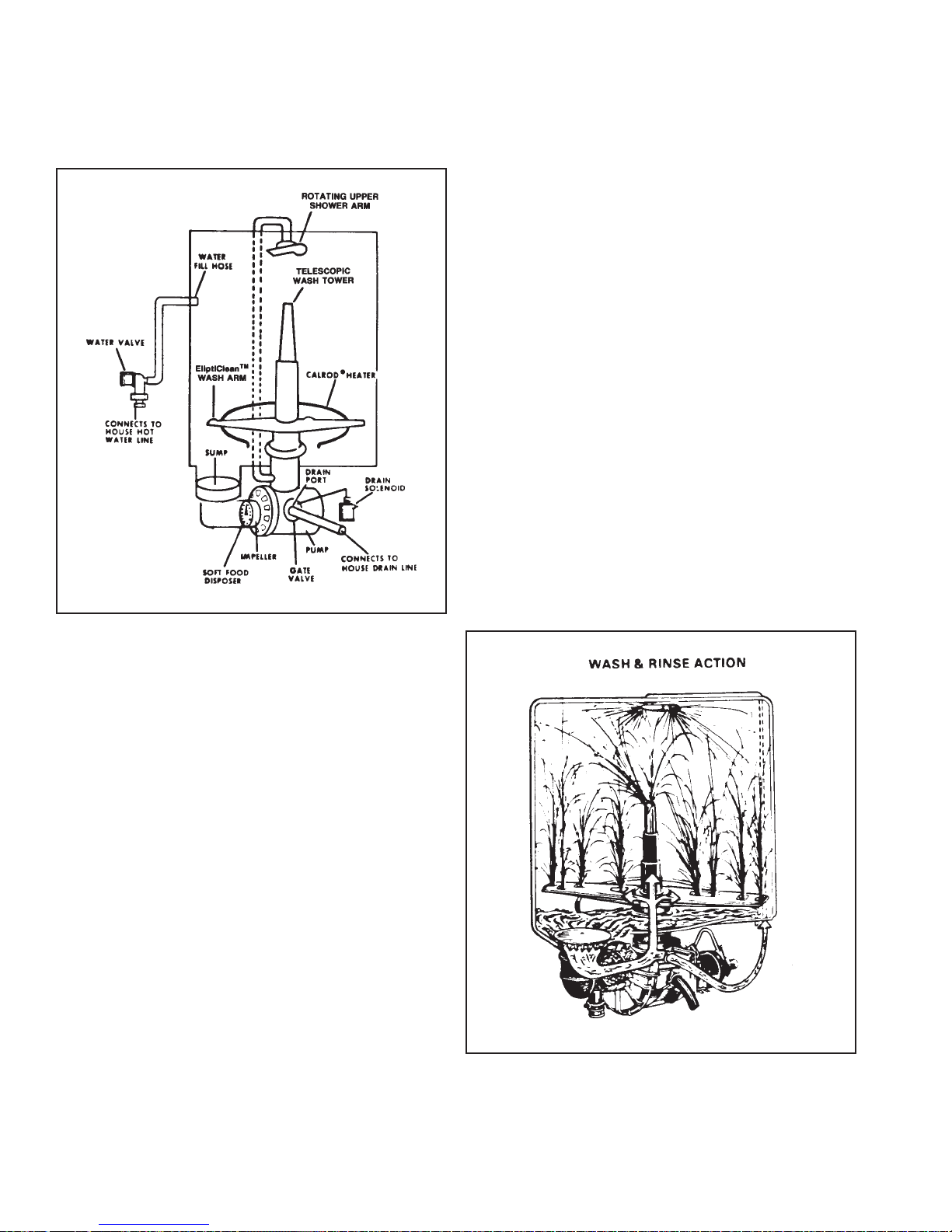
Basic Components
Illustration identifies the basic parts of the dishwasher.
Hot water supply connects to water valve which controls
flow through the water fill hose into side of tub.
When pump motor is energized, gate valve at the exit of
pump controls whether water is recirculated back into
tub (when drain solenoid is not energized) or out of drain
port (when drain solenoid is energized). Sump at bottom
of tub is connected to pump, so when pump motor is
energized water is either drained out or recirculated.
At entry to pump a
amounts of soft food which are pumped out of
dishwasher during drain periods. Soft food disposer
does not need to be cleaned by user.
Water recirculated into dishwasher tub goes up a hollow
tube connected to a rotating wash arm (sometimes
called spray arm) and telescoping wash tower. On some
models, a port off the pump housing channels water up
to enter the top of tub through the rotating upper shower
arm.
Calrod® sheathed heating unit is located at bottom of
tub.
Soft Food
disposer pulverizes small
Basic Functions
During normal wash cycle, dishwasher performs these
functions.
Fill with Hot Water
Enough water is necessary to enable good washing
action. Normal amount of water for a full fill is about 2.0
gallons. Some rinse fills are less.
Actual water level in dishwasher is controlled indirectly;
amount of water fill is determined by timer energizing
water valve solenoid for a specified length of time.
Water valve is designed to give a flow rate of 1.8
gallons per minute and is on for 1 minute. Fill would be
1.8 gallons under design conditions. Pump motor is
energized during the fill period.
Wash Action
Hot water is sprayed under pressure onto dishware. This
is accomplished by pumping water up a hollow tube
through tub bottom and into wash arm and three-section
telescoping wash tower fastened to wash arm.
These components rotate from 12 to 40 RPM. Wash
arm is powered by water jet at one end. Water sprayed
on dishware falls to the bottom of the tub and then goes
into sump and back to pump.
On some models there is a shower arm at top of tub. If
used, water comes out of port in pump housing through
a hose to upper shower arm. Water pressure rotates
upper shower arm at about 100 RPM.
RS3300002 Rev. 0 14 August 1997
Page 15

Operation
Action of wash system is exactly the same for washing
and rinsing periods except detergent is introduced
during wash period. A covered detergent cup is tripped
and detergent is dispensed during main wash period
(after fourth water fill in
First wash action period is usually called
Detergent can be used in the first wash period by filling
the open detergent cup. Detergent falls out into tub
when door is closed.
Drain
When drain solenoid is energized, water is pumped out
through drain hose into house plumbing. Pump motor
turns the same direction during wash and drain action,
but gate valve at exit of the pump is opened by drain
solenoid and recirculating opening in bottom center of
tub is closed.
Some water will always be visible in sump area at the
bottom of tub after drain to prevent pump water seal
from drying out.
Normal Wash
cycles).
Pre-wash
.
During heated dry, the calrod heater located in the
bottom of the tub is energized, unless
drying is selected.
For
Heated Dry
minutes.
For
Normal Dry
used in washing and rinsing starts the drying process.
However, it takes several hours for the dishes to
completely dry.
, the calrod heater is on for about 32
, the heat remaining from the hot water
Normal
no-heat
Dry
After last drain out during washing cycle, the pump
motor, which has run continuously until this point, is deenergized.
In convection drying systems, air enters tub at bottom of
door and, as it is warmed, rises and exits through vent
channel openings in top front of door. Vent opening is
closed during washing and rinsing.
August 1997 15 RS3300002 Rev. 0
Page 16

Operation
Inlet, Tub, and Thermostat Temperatures
Drawing shows locations where water temperature is
measured.
120°F inlet water temperature is, by definition, stabilized
temperature when hot water is run at a sink close to
dishwasher. The Use and Care Manual recommends a
candy thermometer to measure water temperature as it
runs into a glass.
120° Inlet Water Capability
Until 1983, most dishwashers required 140°F inlet water.
120°F capability means
1. saving energy by lowering water heater temperatures
to 120°F.
2. best possible washing job is accomplished when
water temperatures are above 120°F. Even if the
water heater is set for 140°F, actual inlet water
temperature is often less.
Water Temperature Boost
When hot water runs into dishwasher tub at room
temperature (normally 70°F), it cools down substantially
after the first fill because the water is sprayed on the
cold tub interior, racks, and dishware. During
subsequent fills tub is not as cool and water does not
cool down as much.
Highly featured models have
using calrod heater during wash periods. A timer is
used to extend wash period and heat water for a
specified time.
When calrod heater is on during wash or rinse, the water
temperature is raised about 0.6°F for each minute it is
on.
Water Temperature Boost
RS3300002 Rev. 0 16 August 1997
Page 17

Operating Instructions
OFF
RINSE
& HOLD
START
CDU220
HEATED DRY
NATURAL DRY
POWER
SAVER
Note:
Before operating dishwasher, read "Important Safety Instructions" section in User Maintenance Instructions.
1. Select
2. Turn knob to
HEATED DRY
Normal Wash
or
3. Latch door.
Cycle Sequence Water Used Cycle Time
NORMAL WASH
Use for average soiled items.
HEATED DRY
Use for fast drying.
NATURAL DRY
Use for no heat drying.
NATURAL DRY
.
Wash/Rinse, Rinse, Wash, Rinse,
Rinse, Rinse
.
(Gallons) (Minutes)
8.6 57
32
August 1997 17 RS3300002 Rev. 0
Page 18

Operating Instructions
POTS
NORMAL
& PANS
WASH
DRY/PLATE
WARMER
OFF
START
LIGHT
WASH
HEATED DRY
CDU300
POWER
SAVER
RINSE
& HOLD
NATURAL DRY
Note:
Before operating dishwasher, read "Important Safety Instructions" section in User Maintenance Instructions.
1. Push
2. Select
3. Select POTS & PANS or NORMAL WASH cycle by turning knob to
POTS & PANS
HEATED DRY
or
NORMAL WASH
or
NATURAL DRY
button, as desired.
.
START
.
or
Select LIGHT WASH, RINSE & HOLD or DRY/PLATE WARMER cycle by turning knob to appropriate setting.
4. Latch door.
Cycle Sequence Water Used Cycle Time
(Gallons) (Minutes)
POTS & PANS
Use for excessively soiled items.
NORMAL WASH
Use for average soiled items.
Wash/Rinse, Rinse, Rinse, Wash,
Rinse, Rinse, Rinse
Wash/Rinse, Rinse, Wash, Rinse,
Rinse, Rinse
10.3 96
8.6 96
LIGHT WASH
Use for lightly soiled items.
RINSE & HOLD
Use to prevent food from drying on
items.
DRY/PLATE WARMER
Use for drying and warming
HEATED DRY
Use for fast drying.
NATURAL DRY
Use for no heat drying.
RS3300002 Rev. 0 1 8 August 1997
Wash/Rinse, Rinse, Wash, Rinse,
Rinse
Rinse, Rinse
7.1 86
3.1 12
32
32
Page 19

Operating Instructions
WASH TEMP BOOST
ON OFF
DRY/PLATE
WARMER
OFF
START
SHORT
WASH
ADU3000
HOT DRY
RINSE & HOLD
COOL DRY
Note:
Before operating dishwasher, read "Important Safety Instructions" section in User Maintenance Instructions.
1. Push
2. Select
3. Select NORMAL WASH cycle by turning knob to
WASH TEMP BOOST ON
HOT DRY
or
COOL DRY
button, if desired.
.
START
.
or
Select SHORT WASH, RINSE & HOLD OR DRY/PLATE WARMER cycle by turning knob to appropriate
setting.
4. Latch door.
Cycle Sequence Water Used Cycle Time
(Gallons) (Minutes)
NORMAL WASH
Use for average soiled items.
SHORT WASH
Use for a quick cycle.
Wash/Rinse, Rinse, Wash, Rinse,
Rinse, Rinse
Wash/Rinse, Wash, Rinse, Rinse,
Rinse
8.6 63
7.0 53
RINSE & HOLD
Use to prevent food from drying on
Rinse, Rinse
4.3 12
items.
DRY/PLATE WARMER
Use for drying and warming
HEATED DRY
Use for fast drying.
32
32
NATURAL DRY
Use for no heat drying.
*
WASH TEMP BOOST
Increases water temperature for improved wash performance.
August 1997 19 RS3300002 Rev. 0
Page 20

Operating Instructions
POTS
& PANS
NORMAL
WASH
WATER TEMP BOOST
ON
OFF
WATER
HEAT
DRY/PLATE
WARMER
OFF
RINSE
& HOLD
START
ADU5000
SHORT
WASH
HEATED
DRYING
NATURAL
DRYING
Note:
Before operating dishwasher, read "Important Safety Instructions" section in User Maintenance Instructions.
1. Push
2. Select
3. Select POTS & PANS or NORMAL WASH cycle by pushing
WATER TEMP BOOST ON
HEATED DRYING
turning knob to
STAR T
button, if desired.
or
NATURAL DRYING
.
.
POTS & PANS
or
NORMAL WASH
or
Select SHORT WASH, RINSE & HOLD or DRY/PLATE WARMER cycle by turning knob to appropriate
setting.
4. Latch door.
Cycle Sequence Water Used Cycle Time
(Gallons) (Minutes)
POTS & PANS
Use for excessively soiled items.
NORMAL WASH
Use for average soiled items.
SHORT WASH
Use for a quick cycle.
RINSE & HOLD
Use to prevent food from drying on
items.
Wash/Rinse, Rinse, Rinse, Wash,
Rinse, Rinse, Rinse
Wash/Rinse, Rinse, Wash, Rinse,
Rinse, Rinse
Wash/Rinse, Wash, Rinse, Rinse,
Rinse
Rinse, Rinse
10.2 63
8.8 63
7.0 63
4.3 12
button then
DRY/PLATE WARMER
Use for drying and warming.
HEATED DRY
Use for fast drying.
NATURAL DRY
Use for no heat drying.
*WATER TEMP BOOST increases water temperature for improved wash performance.
RS3300002 Rev. 0 2 0 August 1997
32
32
Page 21

Operating Instructions
ADU6000
POTS
& PANS
HEAVY
WASH
NORMAL
WASH
LIGHT
WASH
WATER TEMP
BOOST
RESET
HEATED
DRYING
CLEAR/
CANCEL
WATER
HEAT
START
DELAY
HRS TO START
OFF
DRY/PLATE
WARMER
5
3
RINSE
& HOLD
1
START
SHORT
WASH
Note:
Before operating dishwasher, read "Important Safety Instructions" section in User Maintenance Instructions.
1. Push
2. Push
WATER TEMP BOOST
HEATED DRYING
button, if desired.
button, if desired.
3. If START DELAY is desired, turn knob clockwise to desired delay time.
4. If START DELAY is not desired, do one of the following:
• Select POTS & PANS, HEAVY WASH, NORMAL WASH or LIGHT WASH cycle by pushing
PANS, HEAVY WASH, NORMAL WASH
or
LIGHT WASH
button then turning knob to
START
POTS &
.
• Select SHORT WASH, RINSE & HOLD or DRY/PLATE WARMER cycle by turning knob to appropriate
setting.
5. Latch door.
Cycle Sequence Water Used Cycle Time
POTS & PANS
Use for excessively soiled items.
HEAVY WASH
Use for heavily soiled items.
NORMAL WASH
Use for average soiled items.
SHORT WASH
Use for a quick cycle.
LIGHT WASH
Use for lightly soiled items.
RINSE & HOLD
Use to prevent food from drying on
items.
DRY/PLATE WARMER
Use for drying and warming
HEATED DRY
Use for fast drying.
Wash/Rinse, Rinse, Rinse, Wash,
Rinse, Rinse, Rinse
Wash/Rinse, Rinse, Rinse, Wash,
Rinse, Rinse, Rinse
Wash/Rinse, Rinse, Wash, Rinse,
Rinse, Rinse
Wash/Rinse, Wash, Rinse, Rinse,
Rinse
Wash/Rinse, Rinse, Wash, Rinse,
Rinse
Rinse, Rinse
(Gallons) (Minutes)
9.9 63
9.9 63
8.4 63
6.9 55
7.7 63
3 9
32
32
CLEAR/CANCEL
Use for no heat drying.
August 1997 21 RS3300002 Rev. 0
Page 22

Operating Instructions
ADU7000
POTS
& PANS
HEAVY
WASH
NORMAL
WASH
LIGHT
WASH
CHINA
CRYSTAL
RINSE
WATER TEMP BOOST
& HOLD
ON OFF
HEATED
DRYING
NATURAL
DRYING
WATER
HEAT
START
DELAY
DRY/PLATE
WARMER
HRS TO START
5
7
9
OFF
START
1
3
Note:
Before operating dishwasher, read "Important Safety Instructions" section in User Maintenance Instructions.
1. Push
2. Select
WATER TEMP BOOST ON
HEATED DRYING
or
NATURAL DRYING
or
OFF
button as desired.
as desired.
3. If START DELAY is desired, turn knob clockwise to desired delay time.
4. If START DELAY is not desired, do one of the following:
• Select POTS & PANS, HEAVY WASH, NORMAL WASH, LIGHT WASH, CHINA/CRYSTAL or RINSE
& HOLD cycle by pushing
CRYSTAL
or
RINSE & HOLD
POTS & PANS, HEAVY WASH, NORMAL WASH, LIGHT WASH, CHINA/
button then turning knob to
START
.
• Select SHORT WASH, RINSing or DRY/PLATE WARMER cycle by turning knob to appropriate
setting.
5. Latch door.
SHORT
WASH
Cycle Sequence Water Used Cycle Time
POTS & PANS
Use for excessively soiled items.
HEAVY WASH
Use for heavily soiled items.
NORMAL WASH
Use for average soiled items.
SHORT WASH
Use for a quick cycle.
LIGHT WASH
Use for lightly soiled items.
CHINA/CRYSTAL
Use for delicate items.
RINSE & HOLD
Use to prevent food from drying on
items.
DRY/PLATE WARMER
Use for drying and warming
Wash/Rinse, Rinse, Rinse, Wash,
Rinse, Rinse, Rinse
Wash/Rinse, Rinse, Rinse, Wash,
Rinse, Rinse, Rinse
Wash/Rinse, Rinse, Wash, Rinse,
Rinse, Rinse
Wash/Rinse, Wash, Rinse, Rinse,
Rinse
Wash/Rinse, Rinse, Wash, Rinse,
Rinse
Wash/Rinse, Rinse, Wash, Rinse,
Rinse
Rinse, Rinse
(Gallons) (Minutes)
9.9 63
9.9 63
8.4 63
6.9 55
7.7 63
7.3 63
3 9
32
HEATED DRYING
Use for fast drying.
NATURAL DRYING
Use for no heat drying.
*WATER TEMP BOOST increases water temperature for improved wash performance.
RS3300002 Rev. 0 2 2 August 1997
32
Page 23

Service Information
Water Valve and Inlet System
Fill hose runs up left side of tub and is fastened by a
clamp to fill funnel. Plastic tub has plastic fill funnel
vibration-welded to the plastic tub. Plastic tub is not a
replacement part.
A special insulator block is snapped over two water
valve solenoid coil terminals. This block is anchored to
the bracket to prevent harness leads from being pulled
off solenoid terminals during installation.
Disassembly
1. Remove two screws mounting water valve to left
front frame.
2. To remove insulator block, unlatch two plastic tangs;
one at front and one at harness end of block.
• Solenoid De-energized: Plunger closes center hole in
diaphragm. Water through bleeder hole causes
pressure in plunger guide to push down diaphragm
and close valve.
Note: Water valve solenoid is controlled by switch
contacts in timer, not by float switch.
With a full water fill, water level in tub bottom should be
3/8 inch to 1 inch above the pedestal in bottom of tub.
Valve in Closed Plunger Raised to
Position Open Pilot Hole
Water in Valve
Guide Escapes
Fill Funnel is Welded to Plastic Tub
Water Valve Operation
A hose connects to the outlet of the water valve and
runs to a water inlet in the side of the tub. All inlets have
an air break. Water valve operation is shown in
drawings.
• Closed Position: Plunger closes center hole in
diaphragm. Bleeder hose lets water pressure equalize
in plunger housing.
• Solenoid Energized, Plunger Raised: Water flows out
of plunger housing.
• Water Flow: Water line pressure pushes diaphragm
up allowing water flow past diaphragm. Flow washer
controls amount of water flow at 15 to 175 P.S.I. to
constant 1.80 gallons/minute.
Incoming Water Plunger Drops Pressure Lifts Closes Pilot Hole
Diaphragm - Pressure in Valve
Valve Opens Guide Closes Valve
All water valves may be replaced as complete
assemblies. Screen and washer gasket for water line
connections are available in replacement kit.
Open solenoid coils and clogged or restricted screens
are the most common faults.
August 1997 23 RS3300002 Rev. 0
Page 24

Service Information
g
Chart shown below outlines plumbing corrections that
are recommended to reduce or eliminate water valve
noise.
POSSIBLE CA USE REPAIR
1. Drain air gap restricted. Clean air gap.
2. Kink in drain hose. Replace or reposition hose.
3. Disposer stopped up.
(Some installations don’t
have a drain air gap. Instead
dishwasher drains directly
into disp o se r.)
4. Pump gate valve did not
return after normal pump
out.
5. Drain sensor switch closed
or shorted.
6. Drain solenoid plunger stuck
down.
7. Food soil in filer chamber. Remove filter screen and check
8. Check valve in filter
chamber not sealin
9. Pump inlet partially clogged. Clean inlet sump.
.
Float Switch
The flood, or float, switch protects against overflow.
Switch itself is captured in a plastic housing mounted
underneath tub bottom by a torx-head screw. Housing
cover snaps into place holding switch in correct position.
Housing also serves as an insulator over switch
terminals.
Stem from float inside tub holds switch arm down in
closed position during normal operation. Float is
covered by a plastic domed cover at front left corner of
tub. When water rises above a certain level in tub, float
switch stem rises and switch contacts open to
disconnect power to water valve solenoid.
Float switch will not furnish flood protection if water
valve mechanically sticks in open position. It will furnish
flood protection if timer stalls during fill period or if
switch contacts in timer freeze closed.
Run the disposer to clean it out.
Clean out dishwasher port.
Replace motor pump
mechanism.
Replace switch.
Replace solenoid.
valv e assem bly in filter
chamber. Clean if required.
Swollen or distorted. Check
leakage around threads.
Disassembly
1. Float switch can only be accessed from under tub.
2. Open snap cover on housing to remove switch.
Recalibration
1. Hold scale or rule against bottom of switch bracket
and center of large hole in bracket.
2. Press switch arm down until switch trips.
3. Read the dimension on the scale or rule at the point
where switch trips. It should measure between 5/8
and 3/4 inch.
4. If adjustment is necessary, bend switch arm at point
between stiffening rib and button on switch.
RS3300002 Rev. 0 2 4 August 1997
Page 25

Service Information
!
Motor/Pump Mechanism and Boots
Pump mechanism is supported by wire hangers from
metal plate under dishwasher tub.
Notice flexible plastic heat shield clipped into slots in
metal plate under tub. Heat shield prevents some hot air
from motor from blowing onto the electrical junction box
so temperature does not rise above acceptable limits.
Because of the limited work space under tub, it is
recommended dishwasher be pulled and tipped back to
replace the pump mechanism.
Pump connector boot and sump boot are the same part
and mount the same on all models.
Drain solenoid bracket is very heavy gauge to lessen
chance of bracket being bent causing drain solenoid
problems
All models use same pump mechanism. ADU7000
model has an induction motor; disassembly procedures
are the same.
Snap insulator covers used on motor leads and drain
solenoid terminals.
A plastic insulator block covers the harness lead
terminals to the drain solenoid. Insulator block is
anchored to solenoid to prevent pulling leads off during
installation. Block is held together by two tangs, one on
top and one at the harness end of block.
Two plastic insulator cylinders are used over the
connector terminals on the black wire motor leads to
capture terminals and prevent them from being pulled
apart from harness leads. Limited vertical space can
make removal of insulator cylinders difficult.
Motor/Pump Mechanism Check
If motor hums but does not pump, the cause may
mechanical lockup or frozen bearings, check:
1. Remove power. Try to turn fan blade clockwise to
determine if seal is stuck and can be broken loose. If
motor shaft cannot be turned, cutter blade may be
blocked. Proceed to step 2.
2. On inside of dishwasher, remove sump cover.
Remove grid and reach down into sump. Check for
blockages such as bones, wire ties, glass or
toothpicks. Check “pocket” on left side of sump; if it
contains debris, clean thoroughly. If motor shaft still
cannot be turned, replace motor/pump mechanism.
Motor/Pump Removal
1. Remove sump cover and grid. With sponge or
syringe, remove all water from sump.
2. Remove harness leads to motor.
3. Hose clamps fasten the sump boot and spray arm
boot to the pump housing. Remove two 5/16" bolts
from hose clamps. Find and loosen 5/16" bolt
holding sump boot spring clamp. Loosen clamp from
spray arm connector boot.
4. Disconnect drain hose and rotating upper shower
arm hose.
5. Remove hanger that holds motor to tub.
6. Motor/pump mechanism can now be removed from
under dishwasher. Some water will probably still be
present in hoses or pump; protect floor and other
areas if necessary to prevent damage.
WARNING
Power must be disconnected before attempting to
measure electrical resistance.
Turn dishwasher on and attempt to run motor.
If motor does not run, and does not hum, check:
1. House fuse or circuit breaker.
2. Door switch.
3. Timer plug and harness connections at timer. Be
sure terminals are fully seated.
4. Disconnect harness plug to motor leads. Check for
120 VAC.
5. After removing power, check motor winding
continuity on RX1 scale.
August 1997 25 RS3300002 Rev. 0
Page 26

Service Information
Motor/Pump Replacement Parts
The entire mechanism, including drain solenoid and
associated parts, is available as a replacement part. In
addition, these repair parts are furnished:
Drain Solenoid and associated parts—cutter, grader,
seal impeller kit, slinger, pump housing, lip seal kit
(diverter valve shaft).
The diverter (or gate) valve inside the housing is not
replaceable.
Reassembly
If mechanism is replaced with dishwasher in place,
follow seven steps below in sequence. Following these
steps should give the most reliable results because the
mechanism can be moved around somewhat to
correctly position the two bolts and clamps.
1. Connect spray arm boot, clamp screw at left, head to
front.
2. Connect sump boot, clamp screw at bottom, head to
left.
3. Install motor hangers.
4. Connect power shower hose (if used).
5. Connect drain hose.
6. Replace wiring and insulator blocks.
7. Check for water leaks.
2. Remove pump impeller. Hold motor fan blades and
turn impeller with pliers.
3. Remove seal from impeller. Seal presses in place by
hand. Seal seat remains in place in housing.
Disassemble housing from motor to remove and
replace seal seat.
4. The plastic slinger on the motor shaft must be
replaced if slinger bulges out due to rust buildup on
shaft. If slinger is not replaced, it can contribute to
new seal leaking.
When reassembling housing, it is recommended
centering sleeve be used to center motor shaft
inside seal set in the housing. If centering sleeve is
not used, be very careful to visually center motor
shaft in seal seat when housing mounting screws are
tightened.
5. Seal kit is furnished for replacing the water seal on
diverter valve shaft where it enters pump housing.
Seal washer, stainless steel washer, and retaining
ring are included in kit.
Soft Food Disposer
A spring cutter is used on the soft food disposer
mechanism. A spring cutter is included in the cutter,
grader, seal, impeller kit.
Disassembly
1. Spring cutter: Remove grader nut, using flat-blade
screwdriver or similar tool. Lift grader over spring
cutter, and remove wear ring base and wear ring.
These parts are shown in the illustration.
If smaller seeds or other foreign objects get caught
between the wear ring and impeller, they can jam
pump. The wear ring floats with the impeller and
maintains water pressure around the circumference.
To remove the spring cutter, grasp the bottom edge
of the spring with a long-nose pliers and turn
counterclockwise.
RS3300002 Rev. 0 2 6 August 1997
Page 27

Service Information
!
Drain Solenoid
WARNING
Power must be disconnected before attempting to
measure electrical resistance.
1. Check continuity of solenoid coil on low ohm scale.
2. Check armature for binding. The armature should
bottom before the gate is completely closed.
Mounting plate must not be bent.
3. When replacing solenoid coil, both springs
in place.
must
be
Spray Arm
Spray arm speed should be between 12 and 35 RPM.
1. Spray arm must rotate freely. If it binds, remove
tower (right hand threads).
2. Lift out tower assembly.
3. Inspect spray arm for seeds, bits of china, etc., that
may clog holes—also check for slits or cracks along
sides of arm.
4. Spray arm hub and entire spray arm assembly is
removed and replaced as an assembly. Reverse to
reassemble.
Racks
The lower rack rollers are the same on all models.
Two slight depressions have been molded into inner
door liner to avoid roll in of lower rack when pulled out
for unloading. The two front rollers rest in these
depressions when lower rack is fully pulled out.
To remove upper rack, remove plastic retainer caps on
the ends of the slides. The retainer cap can be removed
with a flat blade screwdriver, by prying back the member
that fits into slide and then pivoting retainer cap inward.
Assemble cap in reverse order.
Rotating Upper Shower Arm
This option is not used on all models.
Hose to rotating upper shower arm connects to port in
pump housing supplying water during wash and rinse
periods. If upper shower arm is not used, a rubber cap is
clamped over this port on pump housing.
Nozzle is a single plastic part which snaps into power
shower spray arm. Studs on nozzle are inserted into top
of the tub (from inside of tub). Metal palnut fasteners
are then driven onto studs to secure plastic nozzle plate
to top of tub.
August 1997 27 RS3300002 Rev. 0
Page 28

Service Information
Filter System
Drawing shows filter system in operation during wash
action. Wash water splashes against and runs down
back of tub. Eventually all wash water does this during
wash period.
Soil-laden wash water flows through inlet into screened
off area at bottom rear of tub. This water must flow
through fine mesh screen filter to go back into tub sump
for recirculation.
Filter check valve is spring-loaded to be open and allow
heavy soil particles to go down into soil collection
chamber where they are trapped during wash action.
Back flow valve inside tub under filter screen is held
closed by being mechanically coupled to spring-loaded
filter check valve.
Jet in bottom of spray arm constantly sprays water on
filter screen to clean.
Drain Action
During pump out period, drain water flows through soil
collection chamber to flush out debris.
Water flow pressure pushes up filter check valve to seal
opening from pump; flows through the soil collection
chamber; then flows out to check valve mounted under
front of tub. External drain line is connected to
dishwasher at check valve. This check valve is mounted
with Torx-head screws.
Normally closed drain check valve is opened by water
pressure during pump out.
Note: If drain line is not 18 inches above floor level,
pressure of water in tub will cause drain check
valve to open and wash water will drain into
drain hose during wash action.
Filter and Drain
1. Remove filter screen. Check piston valve for
jamming by toothpick or other object. Remove valve
and check spring and rubber parts.
2. Check routing of hose system for kinks.
3. Drain line check valve must pass water in drain line
direction only. Check for partially blocked drain line.
Calrod Heater
Heater is mounted by nuts under the tub to legs or
braces so heater sheath does not come into contact with
tub.
Sump Cover and Baffle Grid
Remove two screws hold sump cover and lift baffle grid
out.
With sump cover and grid removed from inside tub,
reach down into the sump boot and feel soft food cutter
and grader screen at pump inlet. Remove foreign
objects that block grader.
RS3300002 Rev. 0 2 8 August 1997
Page 29

Service Information
Tub Corner Baffles
Two black baffles are used at front lower corners of tub.
Use waterproof rubber cement on surface contacting tub
and press baffles in place during installation.
Door Gasket Replacement
It is not necessary to remove door liner from dishwasher
to replace gasket. To replace gasket, proceed as
follows:
1. Open door and pull old gasket straight up and out of
retainer slot, beginning at one end located at bottom
of door liner. No clip or cement is used to hold
gasket in place.
2. Position one end of new gasket about one inch from
center line at bottom of door liner. Start pressing
new gasket into slot at side of door liner near
bottom.
3. Press gasket firmly into slot completely around two
sides and top of door liner. (Liquid soap or silicone
spray may be used to make this easier to do.)
4. Carefully bend gasket around lower corners of liner
and press remaining two ends of gasket into slot
along bottom edge of door liner.
5. There should be a one to two inch-gap between ends
of gasket along bottom of liner.
Detergent Cup Cover And Latch
The detergent cup is molded as part of inner door panel.
A cam on timer trips cup cover and rinse agent injector.
To remove detergent cup cover and handle shaft, push
in fingers at end of shaft with a 1/4 inch socket.
To access detergent cup trip lever and spring, remove
timer.
To replace detergent cup handle shaft and covers,
follow steps below:
1. Position latch spring on shaft hub as shown below.
Wind spring counterclockwise to hook end on
installation pin.
2. Position shaft and cup with handle pointing up (cover
open).
3. Position latch on handle shaft as shown below, then
press onto shaft until fingers snap in place.
4. Turn latch counterclockwise to position end of spring
onto latch tang.
Door Components
Remove screw under door latch. Close latch halfway.
Then door components are accessible by removing
three screws from each side of inner door and one
screw at the top near latch. Carefully separate inner
door panel from outer door panel and drop outer door.
Rinse Agent Injector
Rinse agent injector can easily be removed as follows:
1. Remove power lower assembly (left hand threads).
2. Using top end of center section, press fingers of
rinse agent injector inward while pulling injector off
door.
3. In reassembling, simply snap in place.
August 1997 29 RS3300002 Rev. 0
Page 30

Service Information
Drying Vent
The grid and baffle are welded together for a one-piece
assembly, mounted by two screws.
Inner door flange above vent is flame treated to keep
water beads from forming. Top inside surface of tub is
similarly treated.
During wash and dry it is normal to see water vapor
coming through vent.
During wash and rinse periods, vent opening in inner
door is sealed off by water splashing up into grooves in
vent assembly as shown in illustration below. At
beginning of dry cycle, when wash action stops, water in
these grooves drains off opening vent during dry.
Push Button Switches
Switch contacts are opened or closed when a specific
push button cycle selection is pressed in. Together with
switches in timer control, push button switches set up
specific electrical circuits for cycle selected.
For the push button switch, the switch contacts remain
closed or open throughout the cycle; the timer switch
contacts open and close as the timer cam turns through
360 degrees.
Control Panel Assembly
Remove cover by lifting tab at each end.
RS3300002 Rev. 0 3 0 August 1997
Page 31

Service Information
!
!
WARNING
Power must be disconnected before attempting to
measure electrical resistance.
Servicing Push Button Switch
1. Remove switch bracket assembly by prying open
tabs and sliding assembly back.
2. Pull off buttons to replace switches. Buttons are not
all put on in same position. Note position of each
button for reassembly.
Switch Contact Chart
A chart titled “Switch” is included with timer cam chart
and schematic wiring diagram in all mini-manuals. This
chart tells which switch contacts are open and closed
when each of the push buttons is depressed. For
example, when
5-6, 9-10, and 17-16 are closed. Each contact is
designated by a number, as opposed to a number and a
letter for timer switches.
NORMAL
is selected, switch contacts
Push Button Switch Test
WARNING
Power must be disconnected before attempting to
measure electrical resistance.
1. Remove power from dishwasher.
2. Remove all wire leads from switch terminals before
making check.
3. Press cycles indicated on pushbutton switch chart,
and check continuity of switch terminals as
indicated.
August 1997 31 RS3300002 Rev. 0
Page 32

Service Information
!
!
Snap On Electrical Components Cover
CAUTION
Always replace snap on electrical component
covers after service is completed.
Remove two screws at top of door. Disconnect plug and
snap off cover.
Timer
Timer mounting plate is fastened with two screws at top,
and two tabs at bottom.
The harness connector block plugs into timer. Two
harness connectors are used on models with rapid
advance timer.
With timer removed, detergent cup trip lever, spring,
timer trip cam and timer knob are accessible.
CAUTION
To prevent breaking knob, do not pry knob out
from front side of escutcheon.
Latch Interlock Switches
Two interlock switches are used and snap in place.
Assemble with flat end of coil spring pointing to left as
shown.
On some models, timer knob is captured in plastic
escutcheon by two tabs on knob. To remove knob, press
in on tabs.
Timer Testing
Close door and press
dishwasher.
1. Check advance of timer. If it doesn’t advance,
remove power and check continuity of timer drive
motor. If tests positive, restore power and check for
voltage at timer motor.
2. Turn control dial slowly through cycle, using coin in
slot of indicator dial. Listen for operation of water
valve, drain solenoid and detergent cup.
3. If any component fails to operate, remove power
from dishwasher and check continuity of component.
If tests positive, restore power and check for voltage
to component from timer control.
NORMAL WASH
button, to start
RS3300002 Rev. 0 3 2 August 1997
Page 33

Service Information
!
!
Door Latch
Door latch mechanism fits onto rear of inner door panel
and is replaceable as an assembly.
Mechanism can be left in place, and can be latched to
hold inner door panel in place while outer door panel
and escutcheon assembly is lowered to open position.
Dishwasher can then be operated with water by
manually closing door interlock switch contacts.
Door interlock switches mounted to back of control
panel escutcheon are closed when door latch is
closed—handle moved all the way to right.
Strike Adjust
Latch strike may be adjusted by loosening two mounting
screws and sliding strike toward rear of tub to increase
latching force and reduce the possibility of leaks around
door gasket. If latch closes too hard—slide strike out
slightly.
Harness leads go directly from timer connector plug or
push button switch terminals to components.
Testing
Check voltage at a component (such as water valve or a
pump motor) before replacing as being inoperative.
If no voltage at component, suspect harness connector
block as possible cause. Check for
• Terminal not secured in block.
• Connect plug halves not pushed together tightly.
• Arcing or burning at terminal.
Use ohmmeter to check for continuity through terminals in
circuit or use a voltmeter to check for voltage on one side
of block but not on other side.
Repair
Complete harnesses for dishwashers are not supplied as
replacement parts.
Use a wire crimper tool to securely fasten new terminals
onto wiring harness leads.
Aluminum T rim Panel
This trim is held onto plastic escutcheon by tabs which
are bent over. To remove, straighten tabs.
Wiring Harness and Connector Plug
WARNING
To avoid an open circuit by damaging or crimping
wires, do not pull on terminal block wires when
removing block from timer.
CAUTION
Disconnect power cord and close water supply
valve before servicing dishwasher. Never energize
electrical power to dishwasher with any panels
removed.
To insure dishwasher is properly grounded, always
replace any ground wires removed during
servicing.
Timer connector plug on wiring harness is covered in
timer section. Always check terminals are securely in
place in this plug when timer problem is suspected.
August 1997 33 RS3300002 Rev. 0
Page 34

Schematic Diagrams
RS3300002 Rev. 0 34 August 1997
ADU3000
Page 35

Schematic Diagrams
August 1997 35 RS3300002 Rev.0
ADU3000
Page 36

Schematic Diagrams
RS3300002 Rev. 0 36 August 1997
ADU5000
Page 37

Schematic Diagrams
August 1997 37 RS3300002 Rev.0
ADU5000
Page 38

Schematic Diagrams
RS3300002 Rev. 0 38 August 1997
ADU6000
Page 39

Schematic Diagrams
August 1997 39 RS3300002 Rev.0
ADU6000
Page 40

Schematic Diagrams
RS3300002 Rev. 0 40 August 1997
ADU7000
Page 41

Schematic Diagrams
August 1997 41 RS3300002 Rev.0
ADU7000
Page 42

Schematic Diagrams
RS3300002 Rev. 0 42 August 1997
CDU220
Page 43

Schematic Diagrams
August 1997 43 RS3300002 Rev.0
CDU220
Page 44

Schematic Diagrams
RS3300002 Rev. 0 44 August 1997
CDU300
Page 45

Schematic Diagrams
August 1997 45 RS3300002 Rev.0
CDU300
 Loading...