

Amana CARDS801 Owner's Manual

Self-Cleaning
Electric
Downdraft Range
Owner's Manual
CARDS801*
* Additional alphanumeric characters
representing other models in series may
follow each model number.
Please Read Manual Before Operating
Range
Installer
Leave this manual and other literature with consumer
for future use.
Customer
Keep these instructions for future reference. If appliance
changes ownership, be sure this manual accompanies
range.

Contents
Model Identification ....................................................2
Important Safety Information .......................................3
ALL APPLIANCES..................................................3
SURFACE COOKING UNITS...................................3
OVENS ..................................................................4
SELF-CLEANING OVENS.......................................4
GLASS/CERAMIC COOKING SURFACES ..............4
VENTILATION HOODS............................................ 4
In Case of Fire ........................................................ 4
Precautions ............................................................4
Installation .................................................................5
Range Location....................................................... 5
Cabinet Opening .....................................................5
Minimum Clearances to Combustible Surfaces ........5
Special Counter Top Conditions ............................... 5
Duct Requirements ................................................. 6
Backwall Duct Location........................................... 6
Floor Duct Location................................................. 6
Duct Length............................................................7
Anit-tip Bracket Installation ..................................... 7
Line Voltage Requirements......................................8
Connecting House Wiring to Range Fuse Box..........8
Installing Side Trim ................................................. 8
Backwall Duct Connection.......................................9
Floor Duct Connection ............................................9
Level Range.......................................................... 10
Removal and Replacement of Range...................... 10
Features .................................................................. 10
Modules ............................................................... 10
Installing Grill Module............................................ 11
Installing Griddle ................................................... 11
Installing Coil, Solid Disk,
and Halogen Element Modules .............................. 11
Removing Coil, Solid Disk,
and Halogen Element Modules .............................. 11
Cooking with Smoke Control Grill Module .............. 11
Cooking with Griddle Module ................................. 12
Cooking with Coil Element Module.........................12
Cooking with Solid Element Module....................... 12
Cooking with Smoothtop Module ........................... 13
Surface Element Settings......................................13
Exhaust Fan......................................................... 13
Oven Light ............................................................ 13
Electronic Oven Control......................................... 14
Oven Signals ........................................................14
Operation................................................................. 14
Quick Reference Instructions................................. 14
Baking.................................................................. 15
Automatic Baking .................................................15
Broiling ................................................................. 15
Self-Cleaning ........................................................16
Delayed Self-Cleaning ...........................................16
Utensils ................................................................... 17
Cooking Utensils................................................... 17
Utensils for Smoothtop Module..............................17
Cooking Guide .........................................................18
Baking Guide........................................................18
Roasting Guide ..................................................... 19
Broiling Guide .......................................................20
Care and Cleaning.................................................... 21
Removing Oven Door............................................. 21
Replacing Oven Light ............................................ 21
Removing Storage Drawer .....................................21
Replacing Fuses................................................... 21
Adjusting Thermostat ............................................ 21
Cleaning ............................................................... 22
Before Calling for Service.......................................... 23
Service Tones and Codes ...................................... 23
Common Questions .............................................. 23
Model Identification
Complete enclosed registration card and promptly return. If registration card is missing, call Consumer Affairs
Department at 1-800-843-0304 inside U.S.A. 319-622-5511 outside U.S.A.
When contacting Amana Refrigeration, Inc., provide product information. Find product information on rating label
located on oven frame behind front of storage drawer. Record following information:
Model Number: __________________________________________________________________________
Manufacturing Number: ____________________________________________________________________
Serial or S/N Number: _____________________________________________________________________
Date of purchase: ________________________________________________________________________
Dealer’s name and address: ________________________________________________________________
Keep a copy of sales receipt for future reference or in case warranty service is required. Any questions or to locate
an authorized servicer, call 1-800-843-0304 inside U.S.A. 319-622-5511 outside U.S.A. Warranty service must be
performed by an authorized servicer. Amana Refrigeration, Inc. also recommends contacting an authorized servicer
if service is required after warranty expires.
2
Important Safety Information
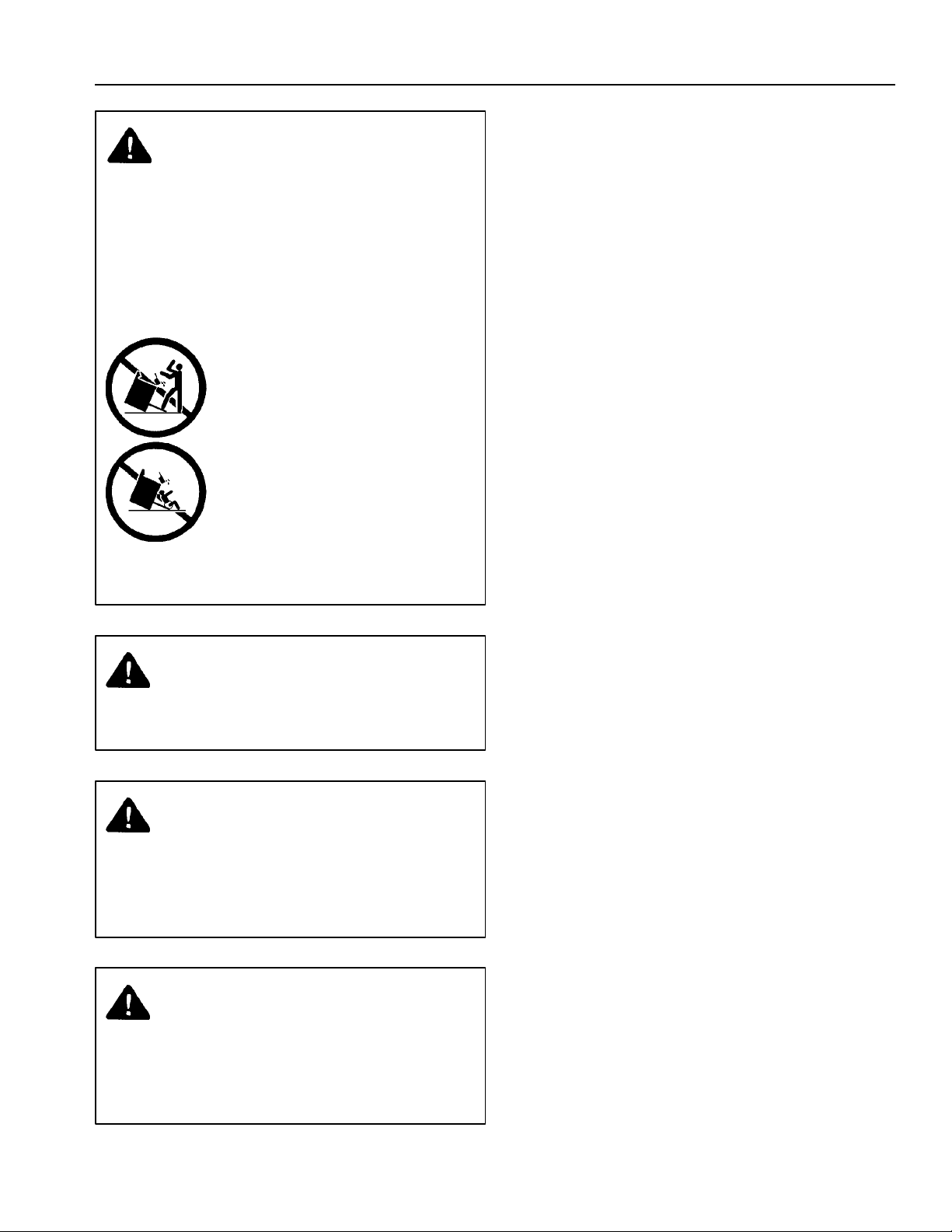
WARNING
To reduce the risk of the appliance tipping, it
must be secured by a properly installed anti-tip
bracket(s). To make sure bracket has been
installed properly, remove the storage drawer
and look under the range with a flashlight.
Bracket(s) must be engaged in the rear corner
of the range.
• ALL RANGES CAN TIP
• INJURY TO PERSONS
COULD RESULT
• INSTALL ANTI-TIP
BRACKET(S) PACKED
WITH RANGE
• SEE INSTALLATION
INSTRUCTIONS
WARNING
To avoid personal injury, do not sit, stand or lean on
oven door or oven drawer.
WARNING
To avoid risk of electrical shock, personal injury, or
death, make sure your range has been properly
grounded and always disconnect it from main power
supply before any servicing.
WARNING
To avoid personal injury or property damage, do not
use grill or griddle if fan is not in operation. In unlikely
event fan is not operating properly contact an
authorized service technician.
ALL APPLIANCES
1. Proper Installation - Be sure your appliance is
properly installed and grounded by a qualified
technician.
2. Never Use Your Appliance for Warming or Heating the
Room.
3. Do Not Leave Children Alone - Children should not be
alone or unattended in the area where the appliance
is in use. They should never be allowed to sit or stand
on any part of the appliance.
4. Wear Protective Apparel - Loose fitting or hanging
garments should never be worn while using appliance.
5. User Servicing - Do not repair or replace any part of
the appliance unless specifically recommended in the
manual. All other servicing should be referred to a
qualified technician.
6. Storage in or on Appliance - Flammable materials
should not be stored in an oven or near surface units.
7. Do Not Use Water on Grease Fires - Smother fire or
flame, or use dry chemical or foam-type extinguisher.
8. Use Only Dry Potholders - Moist or damp potholders
on hot surfaces may result in burns from steam. Do
not let potholder touch elements. Do not use a towel
or other bulky cloth.
SURFACE COOKING UNITS
1. Use Proper Pan Size - This appliance is equipped
with one or more surface units of different size. Select
utensils having flat bottoms large enough to cover the
surface unit heating element. The use of undersized
utensils will expose a portion of the heating element
to direct contact and may result in ignition of clothing.
Proper relationship of utensil to burner will also
improve efficiency.
2. Never Leave Surface Units Unattended at High Heat
Settings - Boilover causes smoking and greasy
spillovers that may ignite.
3. Make Sure Reflector Pans or Drip Bowls Are in
Place- Absence of these pans or bowls during
cooking may subject wiring or components
underneath to damage.
4. Protective Liners - Do not use aluminum foil to line
drip bowls or oven bottoms except as suggested in
the manual. Improper installation of these liners may
result in a risk of electrical shock, or fire.
5. Glazed Cooking Utensils - Only certain types of
glass, ceramic, earthware, or other glazed utensils
are suitable for range top service without breaking due
to sudden change in temperature.
3

Important Safety Information
6. Utensil Handles Should be Turned Inward and Not
Extend Over Adjacent Surface Units - To reduce the
risk of burns, ignition of flammable materials, and
spillage due to unintentional contact with the utensil,
the handle of a utensil should be positioned so that it
is turned inward, and does not extend over adjacent
surface units.
7. Do Not Soak Removable Heating Elements - Heating
elements should never be immersed in water.
OVENS
1. Use Care When Opening Door - Let hot air or steam
escape before removing or replacing food.
2. Do Not Heat Unopened Food Containers - Build-up of
pressure may cause container to burst and result in
injury.
3. Keep Oven Vents Ducts Unobstructed.
4. Placement of Oven Racks - Always place oven racks
in desired location while oven is cool. If rack is
removed while oven is hot, do not let potholder
contact hot heating element in oven.
SELF-CLEANING OVENS
1. Do Not Clean Door Gasket - The door gasket is
essential for a good seal. Care should be taken not to
rub, damage, or move the gasket.
2. Do Not Use Oven Cleaners - No commercial oven
cleaner or oven liner protective coating of any kind
should be used in or around any part of the liner.
3. Clean Only Parts Listed in Manual.
4. Before Self-Cleaning the Oven - Remove broiler pan
and other utensils.
GLASS/CERAMIC COOKING SURFACES
1. Do Not Cook on Broken Cooktop - If cooktop should
break, cleaning solutions and spillovers may
penetrate the broken cooktop and create a risk of
electrical shock. Contact a qualified technician
immediately.
2. Clean Cooktop With Caution - If a wet sponge or cloth
is used to wipe spills on a hot cooking area, be
careful to avoid a steam burn. Some cleaners can
produce noxious fumes if applied to a hot surface.
VENTILATION HOODS
1. Clean Ventilation Hoods Frequently - Grease should
not be allowed to accumulate on hood or filter.
2. When flaming foods under hood, turn fan off. The fan,
if operating, may spread the flame.
In Case of Fire
Fires can occur as a result of over cooking or excessive
grease. Though a fire is unlikely, if one occurs, proceed
as follows:
Surface Element Fire
1. Smother the fire with a nonflammable lid or baking
soda, or use a Class ABC or BC extinguisher. Not
water. Not salt. Not flour.
2. As soon as it is safe to do so, turn the surface
controls to “OFF”.
Oven Fires
1. If you see smoke from your oven, do not open oven
door.
2. Turn oven control to “OFF”.
3. As an added precaution, turn off power at main circuit
breaker or fuse box.
4. Turn on vent to remove smoke.
5. Allow food or grease to burn itself out in oven.
6. If smoke and fire persist, call fire department.
7. If there is any damage to components, call your repair
service before using range.
Precautions
• Do not cook food directly on range top surface,
always use cookware.
• Do not mix household cleaning products. Chemical
mixtures may interact with objectionable or even
hazardous results.
• Do not put plastic items on warm cooking areas.
They may stick and melt.
• Do not slide rough metal objects across range top
surface. Scratching or metal marking can result.
• Do not use cookware with rough bottoms. They
may scratch element surface. Glass and ceramic
cookware can be used on coil elements.
• Do not use damp sponge or dishcloth to clean
range top. A film of soil-laden detergent water may
collect on range top. If this should happen, Amana
ASAP® Cleaner Conditioner removes this type of
stain.
• Do not leave fat heating unless you remain nearby.
Fat can ignite if overheated by spilling onto hot
surfaces.
• Do not allow pots to boil dry on high settings as
this can cause damage to cooking surface and pan.
• Do not use range top surface as a cutting board.
4
Installation
Range Location
Choose a location based on following factors.
• Range is designed to be vented outdoors.
• Electrical rating is 12.5 KW, 120/240 V, 60 Hz.
• Drafts caused by home heating and air conditioning
and open doors or windows can disrupt ventilation
air pattern. Range should not be installed near
windows or doors.
• Range can not be installed in a tunnel type wall
opening. Air currents moving through tunnel can
disrupt ventilation air pattern.
• Range can either be ducted through wall or through
floor to outside.
• Make sure there is adequate space for proper
installation.
• Carefully read all instructions before beginning
installation.
Remove protective packing materials from range. Tape
residue can be cleaned with a soft cloth and alcohol.
Cabinet Opening
WARNING
To avoid risk of burns or fire by reaching over
elements, cabinet storage space located above range
should be avoided.
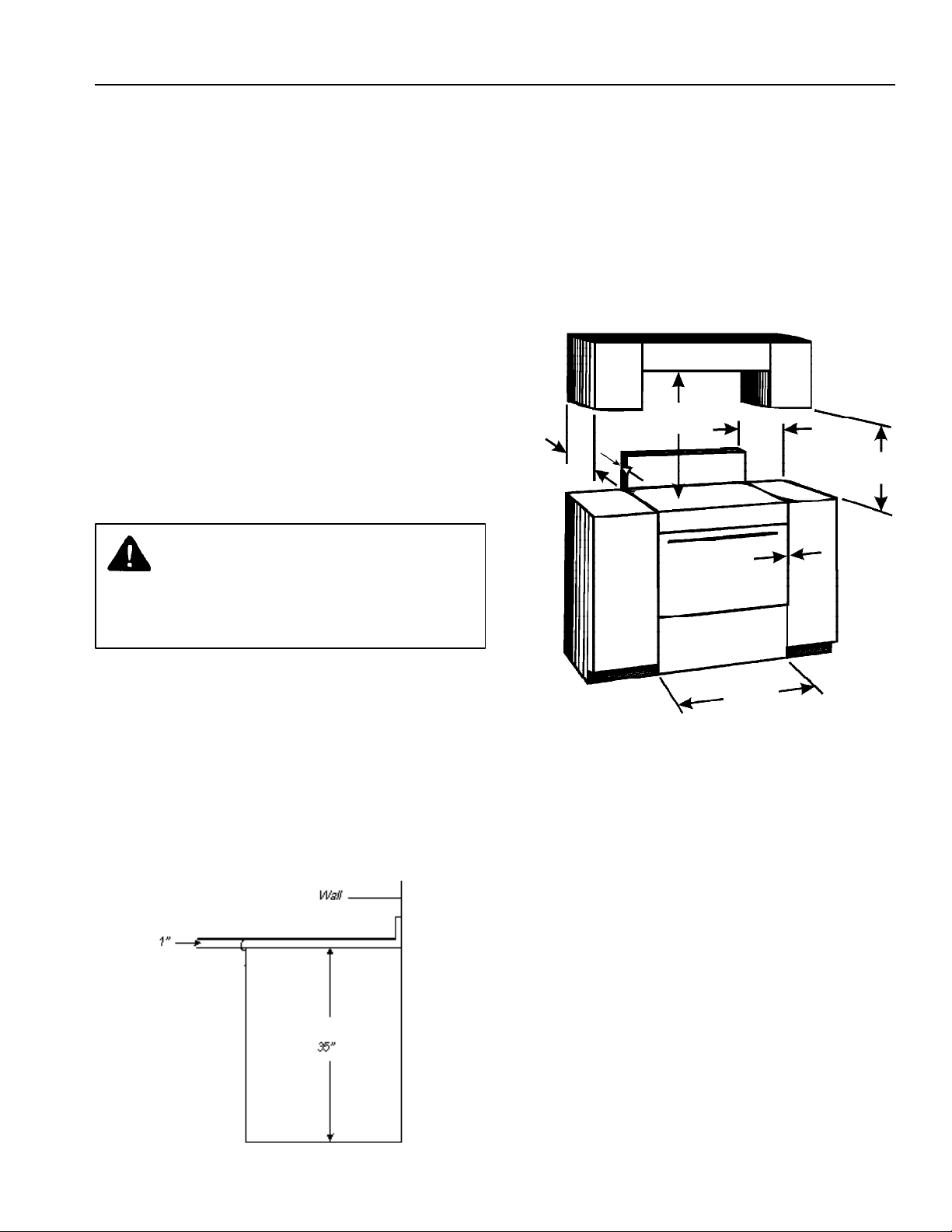
Minimum Clearances to Combustible
Surfaces
• Minimum clearance to rear wall is 0 inches.
• Minimum clearance to a vertical right or left side
wall is 3 inches.
• Minimum clearance to counter top/cabinet on each
side is 0 inches.
• Minimum of 30 inches between top of cooking
surface and bottom of an unprotected wood or
metal cabinet.
30"
Min.
0"
13"
Max.
3"
Both
Sides
0"
18"
Min.
Range should extend approximately 11/2 inch from cabinet
front to oven door handle. Remove venting kit from
storage drawer. Using dimensions in figure below and
shown in Special Counter top Conditions section to
prepare cabinet opening.
Range Dimensions:
WIDTH - 2915/16 inches
DEPTH - 28 inches
HEIGHT - 36 inches
Standard Cabinet and Counter top Height
301/8"
Special Counter Top Conditions
Irregular Cabinet and Counter top Heights
Counter tops such as ceramic tile tops cause cabinet and
counter top to be higher than 36 inches. Follow instructions
below when counter top is higher than 36 inches.
1. Raise leveling legs to maximum level.
2. Measure from floor to side trim. If measurement is
less than height of counter top floor must be
shimmed.
3. Shim floor using a piece of plywood same size as
range opening. Secure plywood to floor. Plywood
must be as secure as original flooring.
4. Install anti-tip bracket and slide range into place.
Island or Peninsula Installation
Island or peninsula installations with 24 inches deep base
cabinets must use flush back cabinets with no rear toe space
to avoid range interference. If a rear toe space is desired, use
27 inches or deeper base cabinets.
5
Slide-in Installation
Backrail
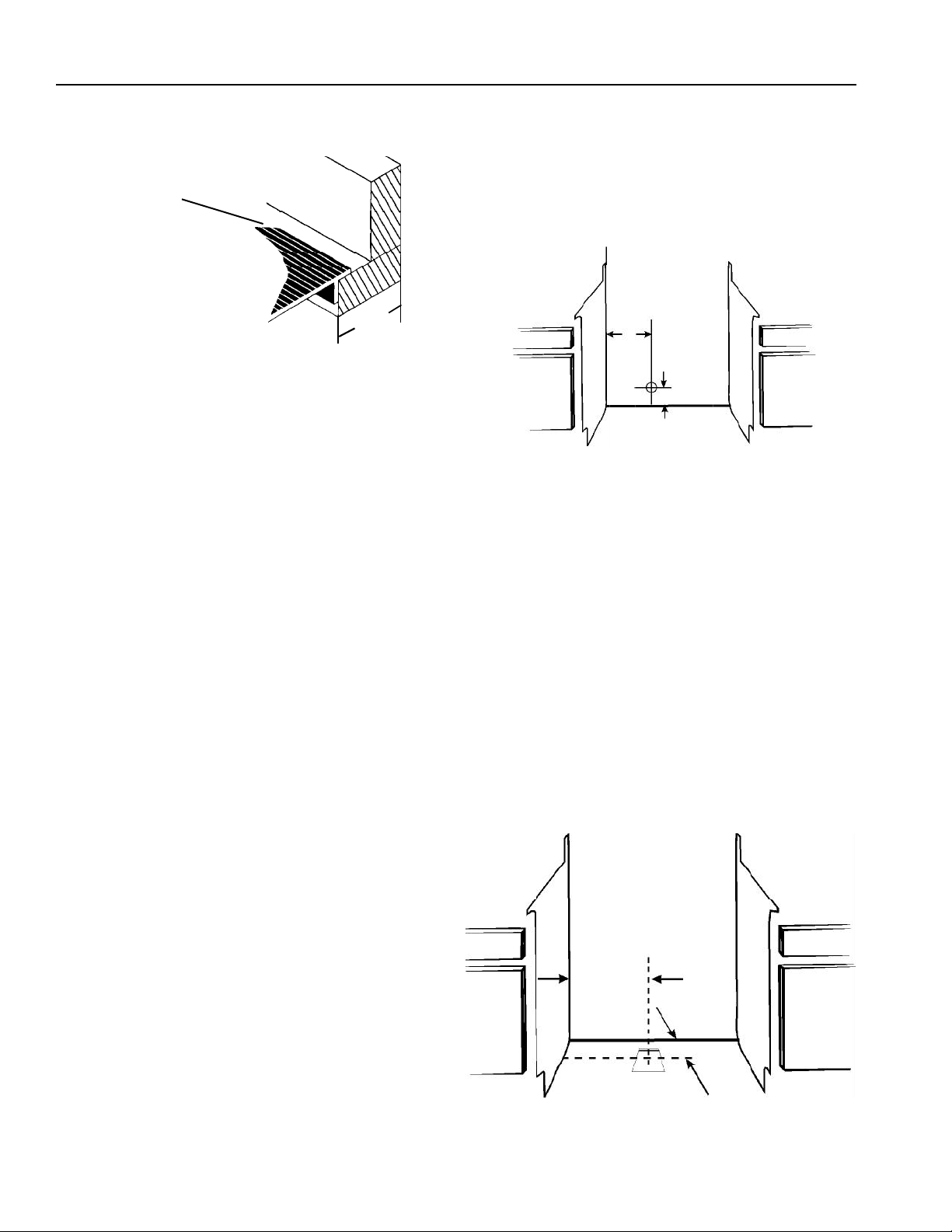
Backwall Duct Location
1. Locate studs in wall.
2. Measure and cut an opening for thimble as illustrated
in figure below. Cutout should be 61/8 inch diameter
circle.
3. Ducting is completed in Backwall Duct Connection
section.
1-3/4"
• For a manufactured counter top, with or without a
backsplash, make cutout keeping rear dimension
as illustrated. The backrail on back of range slides
over manufactured counter top creating a tight fit.
• Backrail may not reach backwall because of
counter top. Corner of backrail can be clipped off
with a pair of wire cutters for a tighter fit.
Duct Requirements
• Duct should be 6 inch round metal ducting. Island
or peninsula installations may require 31/4 X 10 inch
duct.
• To ensure proper ventilation, duct work must not
exceed 60 equivalent feet.
• Curved fittings should not account for more than
50% of duct length.
• Flexible duct is not recommended because of
irregular interior surface. If flexible duct is to be
used, one foot is equal to 2 feet of metal duct.
NEVER USE PLASTIC TYPE DRYER DUCTING.
• Do not vent into an attic or crawl space. Duct range
outside.
• Flexible duct elbows are equal to twice as many
feet as smooth metal elbows.
• Never install two elbow fittings next to each other.
Two elbows installed together create a poor vent
path and insufficient ventilation.
• Seal all duct joints tightly using duct tape.
Openings left in ducting allow smoke and odor to
escape inside house.
• For best performance, do not use over three 90°
elbows.
• 6 inch transition duct provided must be
mechanically secured to exhaust blower outlet.
Secure transition duct using two screws provided.
8"
4-5/16"
Floor Duct Location
1. Locate studs in floor.
2. Measure to locate center of floor duct location. See
figure below.
• For installation with counter top or backsplash
behind range, measure 131/8 inches for dimension
“A”
• For installation without counter top or backsplash
behind range, measure 115/8 inches for dimension
“A”.
3. Cut an opening for floor transition piece as illustrated
in figure below. Cutout should be 71/4 x 71/4 inches
square. If opening is not correctly aligned, duct does
not connect properly.
4. Ducting is completed in Floor Duct Connection
section.
107/8"
A
6
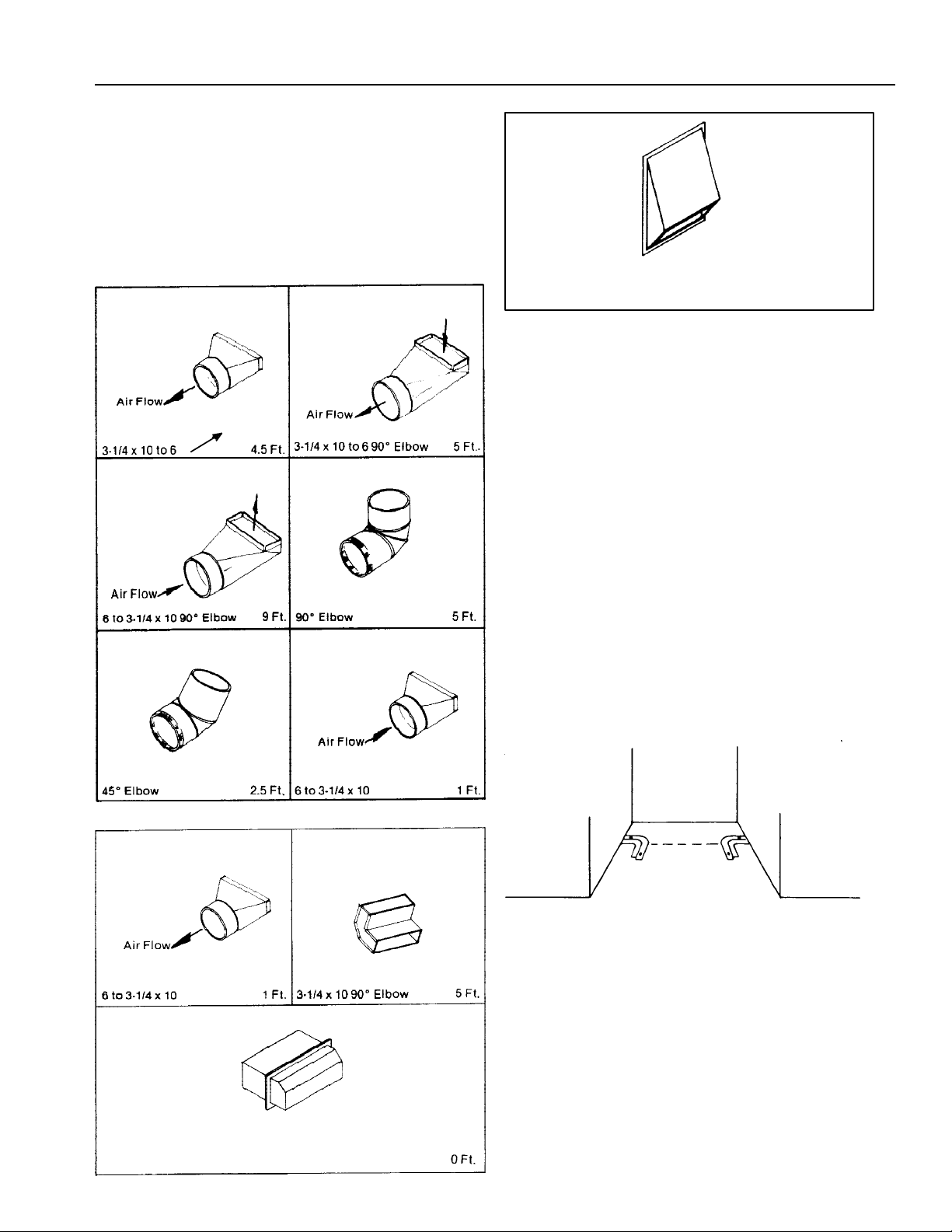
Duct Length
Maximum allowable duct length is 60 equivalent feet.
• Use Recommended Standard Fittings in figures
below to calculate duct length.
• Flexible duct is not recommended. However, if it is
used, one foot is equal to two feet of smooth metal
duct.
Recommended Standard Fittings
(
)
CC30 Wall Cap with Flap = 71/2 Ft.
(available from dealer)
Anit-tip Bracket Installation
To reduce risk of range tipping, secure range with a
properly installed anti-tip devise packed with range.
1. Measure 51/8 inches from back wall on right and left
side of cabinet cutout. Mark measurements on floor
and draw a straight line connecting marks.
(
)
2. Position anti-tip bracket.
• If range is installed beside cabinet(s), place anti-tip
bracket with inside edge over line drawn on floor
and end of bracket against cabinet.
• If range is not installed beside cabinet(s), position
range where it will be installed. Draw a line along
side of range on floor from front to back. Remove
range. Place anti-tip bracket with inside edge over
line drawn 51/8 inches from back wall and end of
bracket over line drawn along side of range on floor.
• Anti-tip bracket can be installed on either right or
left side.
31/4 x 10 Wall Cap without Flap
3. Mark 2 hole locations in anti-tip bracket.
4. Drill 2 holes.
• If drilling into wood, use a 3/32 inch drill bit.
• If drilling into concrete, use a 3/16 inch masonry drill
bit and insert plastic anchors.
5. Secure bracket to floor using screws supplied.
7
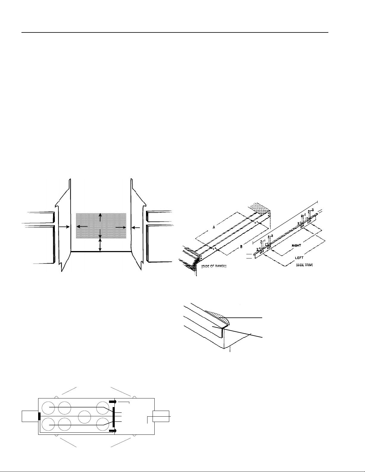
Line Voltage Requirements
Line voltage must not exceed rated voltage. Line voltage
less than rated voltage will result in slow heating. Wiring
system must conform to Underwriters Laboratories, Inc.
standards and Canadian Electrical Code. Installation must
conform to all local, municipal and state building codes,
and local utility regulations. Range must be connected only
to a supply circuit as specified on rating plate wiring diagram
of range. Fuse box must be mounted on floor or wall within
shaded area. See figure below for electrical connection
clearance area.
Wiring diagram is located on bottom side of storage drawer.
This range requires 3 wires, 120/240 Volts, 60 Hertz A.C.
This range is rated at 12.5 K.W. House wiring and fusing
must comply with local wiring codes. If no codes apply,
wire according to Canadian Electrical Codes.
Installing Side Trim
If desired, optional side trim provided can be installed on
range. Side trim must be installed above counter top level
and tapped down into place.
Side trim can be mounted in several different positions
depending on counter top opening, cabinet structure, and
range features.
• Freestanding with Backsplash
To mount trim flush with front of counter top, use #3
trim holes and “A” range holes.
• 4 inch Backrail Kit and Backsplash
To mount trim flush with front of counter top, use #3
trim holes and “A” range holes.
• Optional Mounting
“A” range holes allow an extra 3/8 inch forward
adjustment. Trim holes #1, #2, and #3 allow a 1/2
inch adjustment. Trim can be mounted in any
desired location using holes provided.
Trim Hole Locations
"
235/8
9
/16
"
5"
18"
10"
5"
Connecting House Wiring to Range
Fuse Box
1. Remove 4 screws securing rear cover to fuse box.
2. Feed house wires through hole in end of fuse box.
3. Connect red house wire to red range wire, black
house wire to black range wire, and white house wire
to white range wire using wire nuts.
4. Loop green ground wire around ground screw and
secure using brass nut and washer.
• All connections must be tight.
5. Replace back fuse box cover using screws.
6. Attach box to floor, inside cabinet, or wall.
Remove Screws
Roll Formed Counter Top
15
"
/16
If the counter top front is roll
formed , notch the counter to
allow for overlapping trim.
Side Trim
Remove Screws
Ground Screw
Range Wires
Feed House
Wires Through
8
 Loading...