

Page 1

Wave Oven™ Built-in Trim Kit AXL130
Installation Guide
Page 2
Important Safety Information
Grounding Instructions
WARNING
T o avoid electrical shock, unplug power cord before
installing trim kit.
T o avoid fire, vacuum sawdust and debris from cutout
before installing oven.
CAUTION
T o avoid cuts or other injury , wear gloves or protective
clothing for arms and hands. Kit pieces may have
sharp edges.
CAUTION
T o avoid personal injury and property damage, only
install Amana "AOWS" model Wave Ovens™ above
Amana AO24, AOCS, AOES wall ovens. Any other
combination is untested. Ovens could overheat and
shorten oven life.
WARNING
T o avoid risk of electrical shock or death, this oven
must be grounded.
T o avoid risk of electrical shock or death, do not alter
the plug.
The Amana Wave Oven™ MUST be grounded. In the
event of an electrical short circuit, grounding reduces risk
of electric shock by providing an escape wire for electric
current. This oven is equipped with a cord having a
grounding wire with a grounding plug. The plug must be
plugged into a properly installed and grounded outlet.
Consult a qualified electrician or servicer if grounding
instructions are not completely understood, or if doubt
exists as to whether the oven is properly grounded.
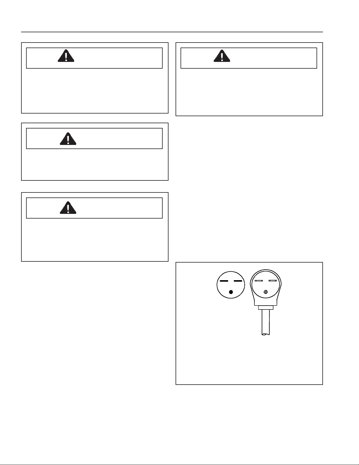
Do not use an extension cord. If oven power cord is too
short, have a qualified electrician install a three-slot
receptacle. This oven should be plugged into a separate
60 hertz circuit with the electrical rating as shown in
drawing. Models rated at 240 supply voltage. When
Amana Wave Oven™ is on a circuit with another
appliance or supply voltage varies, an increase in cooking
times may be required and fuses can be blown.
Receptacle / Plug
NEMA 6-30R/6-30P
250V–30AMP
AOWS2030WW/E/SS
2
Page 3
Materials and Parts
Materials Needed (Not Supplied)
• Phillips and flat blade screwdriver
• 240 volt, 30 amp, 60 Hz electrical receptacle
• Switchbox and cover plate
• Protective gloves
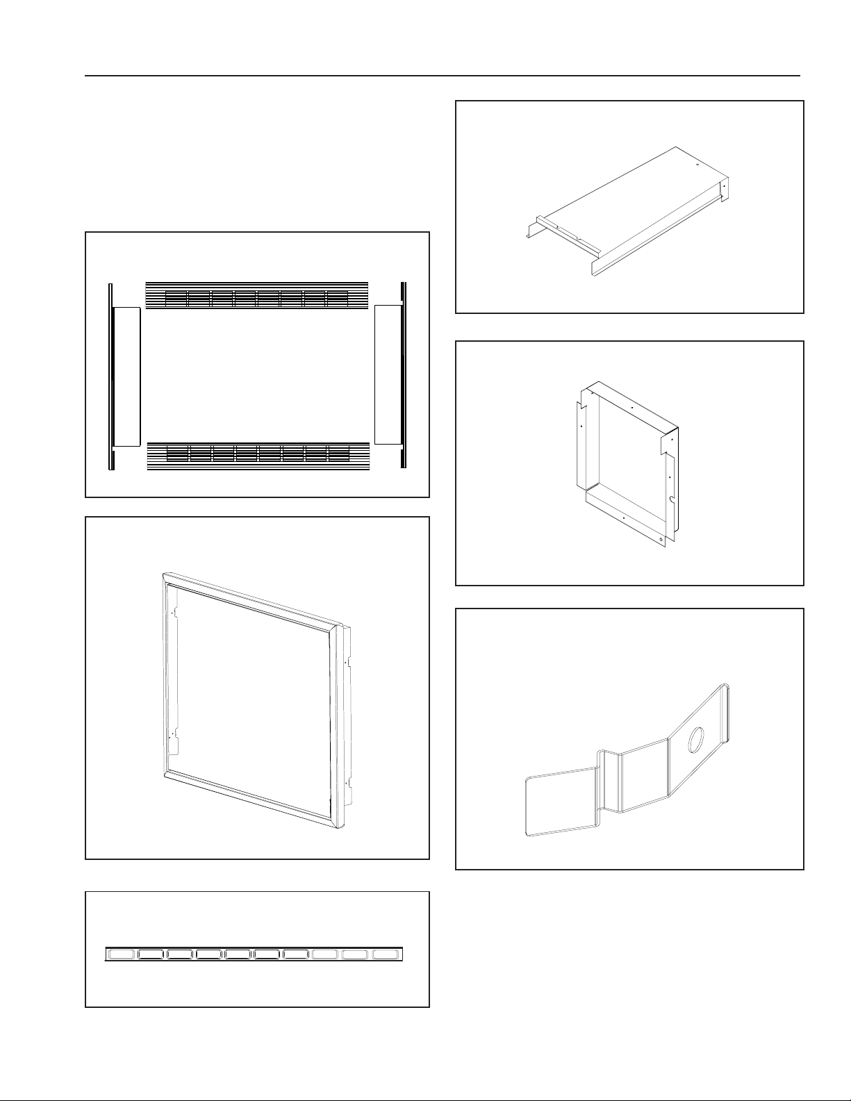
Part Identification
Grille and side trim pieces
T op duct
Rear duct
Perimeter frame
Trim insert
Mounting clip
3
Page 4
Installation
Kit Part Numbers and Quantities
• White parts apply to AXL130WW.
• Black parts apply to AXL130E.
• Stainless steel parts apply to AXL130SS.
Kit Part Numbers
Item Qty. Part
Number
Grille—Top
Black
White
Stainless
Grille—Bottom
Black
White
Stainless
Trim—Side
Black
White
Stainless
Trim insert
Black 2 12301002
Ducts
Top
Rear
Perimeter frame
Black
White
Stainless
Mounting clips 4 12301101
Screws*
Flat head (WW, SS)
Flat head (E)
Pan head
Small (Phillips)
Contact paper* 1 12341301
Insulation* 1 10906513
1
1
1
1
1
1
2
2
2
1
1
1
1
1
8
8
8
3
* Not shown
12300804
12300805
12300806
12300801
12300802
12300803
12300701
12300702
12300703
12300604
12222504
12300901
12300902
12300903
M0213517
M0216417
M0211533
M0211519
Oven Placement
• Do not block air exhaust duct or air filter.
• Install according to all local building codes and
ordinances.
• Amana Wave Oven™ must be built into cabinets. Use
only Amana “AXL” trim kit. Trim kit is designed to be
used with Amana Wave Ovens™ AOWS2030E/WW/
SS.
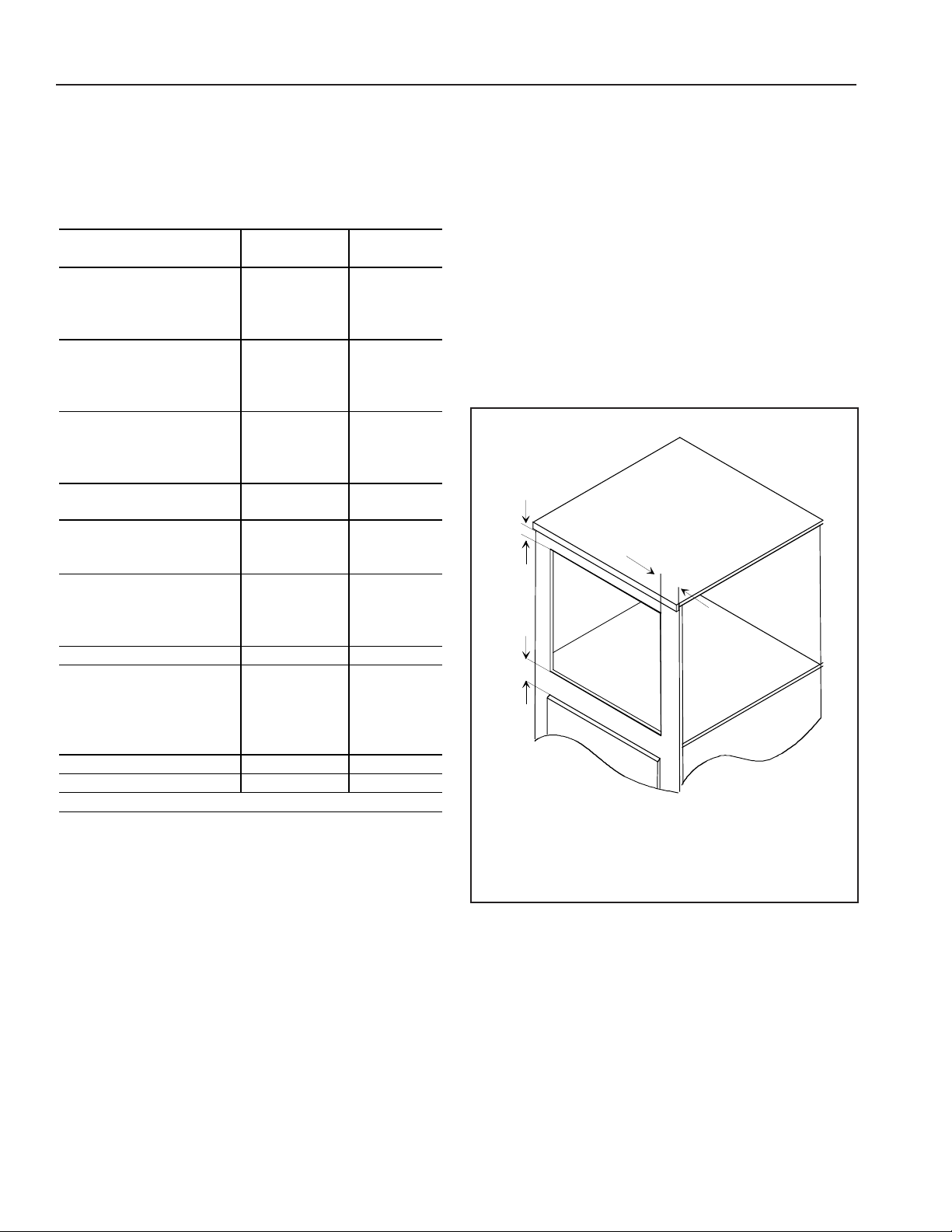
Cabinet Clearances
Dimensions in illustration are minimum distances above,
below, and beside cutout. Install so other appliances and
cabinet trim or doors are at least minimum distance from
cutout.
A
B
C
A—¾" (min.)
B—¾" (min.)
C—2" (min.)
4
Page 5

1. Prepare the wall cutout according to the dimensions
shown below.
• Position cutout at a convenient height for user.
• V acuum sawdust and debris from cutout before
installing oven.
• Attach contact paper to front edge of cutout as
shown. Contact paper masks cabinet behind
bottom grille.
H
2. Route proper wiring to the cutout.
• See "Grounding Instructions" section for electrical
information.
• The electrical receptacle must be flush mounted
on side wall of the cutout.
3. Disconnect power from Amana Wave Oven™ and
remove any loose items inside oven before
proceeding with installation.
4. Remove cord wrap and duct cover if necessary.
• Some models come with cord wrap and duct
cover.
• 3 screws attach cord wrap to back of oven.
• 2 screws attach duct cover to back of oven.
W
D
B
O
(H)eight—197/8"
(W)idth—283/8 (max.)
(D)epth—237/8" (min.)
(B)etween; cutouts—2½" (min.)
(O)verlap; contact paper—2" (max.)
Duct cover
Cord wrap
5. Place rear duct on oven.
• Align duct with screw holes and attach rear duct
with screws. Use screws from duct cover and cord
wrap or 3 screws provided.
5
Page 6

6. Remove adhesive backing and place insulation on top
of oven as shown.
• Use rear duct to align insulation with oven center.
Place adhesive side down
8. Place perimeter frame in cutout and attach with 4
pan head screws.
Insulation
7. Place top duct on top of oven.
• T op duct fits over rear duct.
• Attach top duct with 3 Phillips screws provided.
Screws
.
9. Attach 4 mounting clips to perimeter frame.
6
Page 7

10. Place oven in front of cutout opening and plug in
oven. Slide oven in place.
• Two people should perform this step.
• Ensure oven is accurately centered.
1 1. Assemble trim frame.
• Insert black trim insert into top and bottom
grille pieces.
• Align holes in side trim with channels in top and
bottom grille pieces. Secure with flat head screws.
12. Slip assembled frame over oven with tall grille at the
top.
• Check alignment of trim and oven to be sure
everything is lined up correctly.
13. Snap assembled trim and grille into perimeter frame.
14. Trim kit is now fully installed. Replace any loose
items that might have been removed from oven
interior.
7
Page 8

Part No. 10965903
Printed in U.S.A.
1997 Raytheon Appliances
Amana, Iowa 52204
 Loading...