

Amana AVZC200241AA, AVZC200241AB, AVZC200241AC, AVZC200361AA, AVZC200361AB Installation Manual
...Page 1
HEAT PUMP UNIT
AVZC20 HEAT PUMP
INSTALLATION & SERVICE REFERENCE
Index
IMPORTANT SAFETY INSTRUCTIONS .......................................... 1
SHIPPING INSPECTION ............................................................ 2
CODES & REGULATIONS ........................................................ 2
FEATURES............................................................................ 2
INSTALLATION CLEARANCES .................................................... 2
ROOFTOP INSTALLATIONS........................................................ 3
SAFE REFRIGERANT HANDLING ............................................... 3
REFRIGERANT LINES .............................................................. 3
REFRIGERANT LINE CONNECTIONS........................................... 5
LEAK TESTING (NITROGEN OR NITROGEN-TRACED) ................... 5
SYSTEM START-UP PROCEDURE.............................................. 5
ELECTRICAL CONNECTIONS .................................................... 6
HEAT PUMP ADVANCED FEATURE MENU ............................... 22
WIRING DIAGRAM ............................................................... 25
CAPACITOR ........................................................................ 28
TROUBLESHOOTING .............................................................. 33
ETTING THE MODE DISPLAY ............................................... 38
S
7-S
EGMENT DISPLAY ........................................................... 44
START-UP CHECKLIST .......................................................... 47
I
MPORTANT SAFETY INSTRUCTIONS
The following symbols and labels are used throughout this
manual to indicate immediate or potential safety hazards. It is
the owner’s and installer’s responsibility to read and comply with
all safety information and instructions accompanying these symbols. Failure to heed safety information increases the risk of
personal injury, property damage, and/or product damage.
W ARNING
HIGH VOLTAGE !
D
ISCONNECT
M
ULTIPLE POWER SOURCES MAY BE PRESENT
TO DO SO MAY CAUSE PROPERTY DAMAGE, PERSONAL
INJURY OR DEATH
O
NLY PERSONNEL THAT HAVE BEEN TRAINED TO INSTALL, ADJUST, SERVICE OR
REPAIR (HEREINAFTER
MANUAL SHOULD SERVICE THE EQUIPMENT
BE RESPONSIBLE FOR ANY INJURY OR PROPERTY DAMAGE ARISING FROM
IMPROPER SERVICE OR SERVICE PROCEDURES
ASSUME RESPONSIBILITY FOR ANY INJURY OR PROPERTY DAMAGE WHICH MAY
RESULT
LICENSES TO SERVICE THE EQUIPMENT SPECIFIED IN THIS MANUAL, ONLY
LICENSED PERSONNEL SHOULD SERVICE THE EQUIPMENT
INSTALLATION, ADJUSTMENT, SERVICING OR REPAIR OF THE EQUIPMENT
SPECIFIED IN THIS MANUAL, OR ATTEMPTING TO INSTALL, ADJUST, SERVICE OR
REPAIR THE EQUIPMENT SPECIFIED IN THIS MANUAL WITHOUT PROPER
TRAINING MAY RESULT IN PRODUCT DAMAGE, PROPERTY DAMAGE, PERSONAL
INJURY OR DEATH
ALL
POWER BEFORE SERVICING
.
. F
AILURE
.
, “
SERVICE
”)
THE EQUIPMENT SPECIFIED IN THIS
. THE
MANUFACTURER WILL NOT
. IF
YOU SERVICE THIS UNIT, YOU
. IN
ADDITION, IN JURISDICTIONS THAT REQUIRE ONE OR MORE
. I
.
MPROPER
IOA-4013C
8/2016
“IMPORTANT – THIS PRODUCT HAS BEEN DESIGNED AND MANUFACTURED TO MEET ENERGY STAR CRITERIA FOR
ENERGY EFFICIENCY WHEN MATCHED WITH APPROPRIATE COIL COMPONENTS. HOWEVER, PROPER REFRIGERANT CHARGE
AND PROPER AIR FLOW ARE CRITICAL TO ACHIEVE RATED CAPACITY AND EFFICIENCY. INSTALLATION OF THIS PRODUCT SHOULD
FOLLOW THE MANUFACTURER’S REFRIGERANT CHARGING AND AIR FLOW INSTRUCTIONS. FAILURE TO CONFIRM PROPER
CHARGE AND AIRFLOW MAY REDUCE ENERGY EFFICIENCY AND SHORTEN EQUIPMENT LIFE.”
All information contained herein is subject to change without notice.
© 2015 - 2016 Goodman Manufacturing Company, L.P.
5151 San Felipe St., Suite 500, Houston, TX 77056
www.amana-hac.com
is a registered trademark of Maytag Corporation or its related companies and is used under license. All rights reserved.
Page 2
CAUTION
THE
UNIT HAS ITS OWN PUMP-DOWN MODE
MODE WHILE VACUUMING THE UNIT
CAUSE INTERNAL ELECTRICAL ARCING, RESULTING IN A DAMAGED OR
FAILED COMPRESSOR
S
HIPPING INSPECTION
.
. USE
THE PUMP-DOWN
. V
ACUUMING TOO LOW CAN
Always keep the unit upright; laying the unit on its side or top
may cause equipment damage. Shipping damage, and subsequent
investigation is the responsibility of the carrier. Verify the model
number, specifications, electrical characteristics, and accessories
are correct prior to installation. The distributor or manufacturer
will not accept claims from dealers for transportation damage or
installation of incorrectly shipped units.
C
ODES
& R
EGULATIONS
F
EA TURES
This heat pump is part of a system that uses inverter technology to
more efficiently remove or add heat with better efficiency and
achieve the target comfort conditions. System may ONLY be installed using a ComfortNet™ thermostat with model number
CTK04 as part of the digital communicating system. The
ComfortNet system reduces the number of required thermostat
wires, provides additional setup features and enhanced active
diagnostics. Due to components using inverter technology, the
heat pump will not function properly if used with a CTK03, 02 or
01 ComfortNet thermostat.
NOTICE
NOT
APPROVED FOR USE WITH A
I
NST ALLATION CLEARANCES
CTK01, CTK02 OR CTK03.
This product is designed and manufactured to comply with national codes. Installation in accordance with such codes and/or
prevailing local codes/regulations is the responsibility of the installer. The manufacturer assumes no responsibility for equipment installed in violation of any codes or regulations. Rated
performance is achieved after 72 hours of operation. Rated performance is delivered at the specified airflow. See outdoor unit
specification sheet for split system models or product specification sheet for packaged and light commercial models. Specification sheets can be found at www.amana-hac.com for Amana
brand products. Within the website, please select the residential or commercial products menu and then select the submenu
for the type of product to be installed, such as air conditioners
or heat pumps, to access a list of product pages that each contain links to that model’s specification sheet.
The United States Environmental Protection Agency (EPA) ha s
issued various regulations regarding the introduction and disposal of refrigerants. Failure to follow these regulations may
harm the environment and can lead to the imposition of substantial fines. Should you have any questions please contact the
local office of the EPA.
If replacing a condensing unit, heat pump or air handler, the system must be manufacturer approved and Air Conditioning, Heating and Refrigeration Institute (AHRI) matched.
NOTE: The installation of an inverter heat pump with unmatched
system units will not allow for proper operation.
NOTICE
I
NVERTER
AIR HANDLER OR
RESULTING FROM OPERATION WITH ANY OTHER COMBINATION IS NOT
COVERED BY OUR WARRANTIES
Outdoor inverter units are approved for operation above 0°F in
cooling mode and -20°F (RH10%) in heating mode with no additional kit necessary.
Damage resulting from operation of the units in a structure that
is not complete (either as port of new construction or renovation) is not covered by our warranties.
A/H
MODELS CAN ONLY BE MATCHED WITH AN
TXV-V**
EXPANSION VALVE KIT
.
. D
AV**PVC
AMAGE
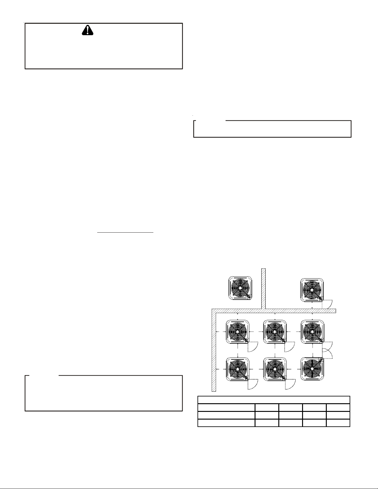
Special consideration must be given to location of the heat pump
unit(s) in regard to structures, obstructions, other units, and any/
all other factors that may interfere with air circulation. Where
possible, the top of the unit should be completely unobstructed;
however, if vertical conditions require placement beneath an ob-
struction there should be a minimum of 60 inches between the
top of the unit and the obstruction(s). The specified dimensions
meet requirements for air circulation only. Consult all appropriate regulatory codes prior to determining final clearances.
®
Another important consideration in selecting a location for the
unit(s) is the angle to obstructions. Either side adjacent the valves
can be placed toward the structure provided the side away from
the structure maintains minimum service clearance. Corner installations are strongly discouraged.
NOT
RECOMMENDED
B B B
AA AAA
C
AA
A
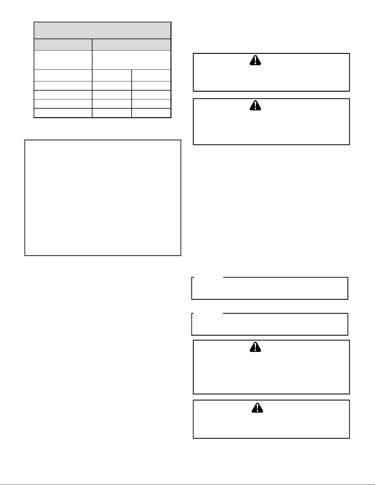
Model Type A B C AA
Residential
Light Commercia l
AA
Minim um Airflow Clear ance
10" 10" 18" 20"
12" 12" 18" 24"
AA
C
AA
CC
B
AA
OK!
OK!
OK!
OK!
OK!
OK!
This unit can be located at ground floor level or on flat roofs. At
ground floor level, the unit must be on a solid, level foundation
2
Page 3
that will not shift or settle. To reduce the possibility of sound
transmission, the foundation slab should not be in contact with
or be an integral part of the building foundation. Care should be
taken to ensure the unit is installed away from noise sensitive
locations such as bedrooms, windows and outdoor living areas.
Ensure the foundation is sufficient to support the unit. A concrete slab raised above ground level provides a suitable base.
R
OOFTOP INST ALLATIONS
If it is necessary to install this unit on a roof structure, ensure
the roof structure can support the weight and that proper consideration is given to the weather-tight integrity of the roof. Since
the unit can vibrate during operation, sound vibration transmission should be considered when installing the unit. Vibration absorbing pads or springs can be installed between the heat pump
unit legs or frame and the roof mounting assembly to reduce
noise vibration.
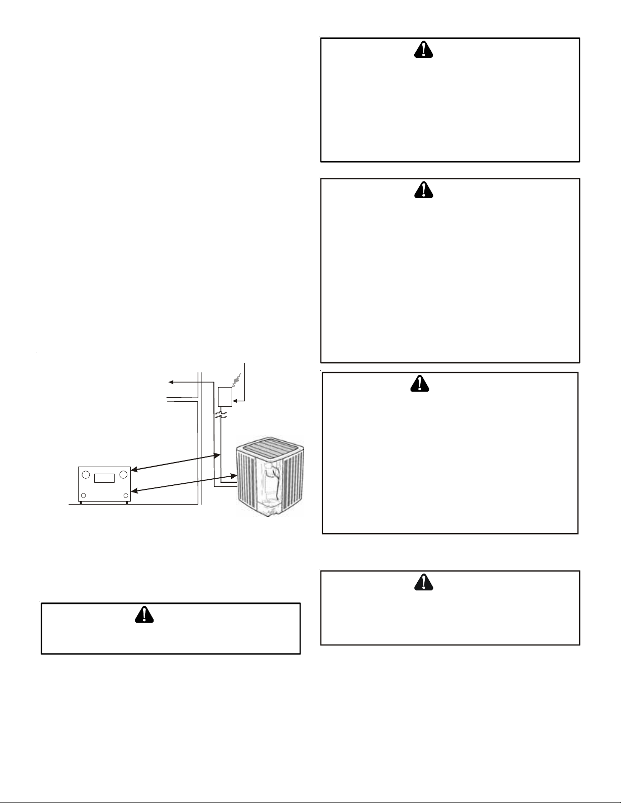
ELECTRICAL NOISE
The unit should be well grounded so that potential effects of
electrical noise from the inverter to surrounding equipment can
be minimized.
When selecting an installation location, keep sufficient distance
from the heat pump unit and wiring to radios, personal computers, stereos, etc., as shown in the following figure.
Circuit
Breaker
To Indoor Unit and Thermostat
WARNING
TO
AVOID POSSIBLE EXPLOSION, USE ONLY RETU RNABL E (NOT
DISPOSABLE) SERVICE CYLINDERS WHEN REMOVING REFRIGERANT FROM
A SYSTEM
• E
• E
• E
W
.
NSURE THE CYLINDER IS FREE OF DAMAGE WHICH COUL D LEAD TO A
LEAK OR EXPLOSION
NSURE THE HYDROSTATI C TEST DATE DOES NOT EXCEED
NSURE THE PRESSURE RATING MEETS OR EXCEEDS
HEN IN DOUBT, DO NOT USE CYLINDER
.
400
.
5
PSIG
YEARS
.
.
WARN ING
R
EFRIGERANTS ARE HEAVIER THAN AIR
OXYGEN IN YOUR LUNGS OR IN ANY ENCLOSED SPACE
POSSIBLE DIFFICULTY IN BREATHING OR DEATH
EVER PURGE REFRIGERANT INTO AN ENCLOSED ROOM OR SPACE
• N
LAW, ALL REFRIGERANTS MUST BE RECLAIMED
F AN INDOOR LEAK IS SUSPECTED, THOROUGHLY VENTILATE THE AREA
• I
BEFORE BEGINNING WORK
IQUID REFRIGERANT CAN BE VERY COLD
• L
OR BLINDNESS, AVOID CONTACT AND WEAR GLOVES AND GOGGLES
LIQUID REFRIGERANT DOES CONTACT YOUR SKIN OR EYES, SEEK MEDICAL
HELP IMMEDIATELY
LWAYS FOLLOW
• A
OISONOUS GAS WILL BE PRODUCED
P
EP A
.
.
REGULATIONS
. T
HEY CAN “PUSH OUT” THE
. TO
AVOID
:
.
. TO
AVOID POSSIBLE FROST BITE
. N
EVER BURN REFRIGERANT, AS
.
. BY
. IF
WARNING
Radio, TV
(In.)
Placement to Minimize Electronic Noise
S
AFE REFRIGERANT HANDLING
”
0
6
e
r
o
m
r
o
”
0
6
e
r
o
m
r
o
While these items will not cover every conceivable situation, they
should serve as a useful guide.
WARNING
TO
AVOID POSSIBLE INJURY, EXPLOSION OR DEATH, PRACTICE SAFE
HANDLING OF REFRIGERANTS
.
TO
AVOID POSSIBLE EXPLOSION
EVER APPLY FLAME OR STEAM TO A REFRIGERANT CYLINDER
•N
MUST HEAT A CYLINDER FOR FASTER CHARGING, PARTIALLY IMMERSE
IT IN WARM WATER
EVER FILL A CYLINDER MORE THAN
•N
REFRIGERANT
EVER ADD ANYTHING OTHER THAN
•N
R-410A
OR
•S
AS
R
EFRIGERANT LINES
CYLINDER
CERTIFIED FOR THE TYPE OF REFRIGERANT USE
TORE CYLINDERS IN A COOL, DRY PLACE
A
PLATFORM OR A ROLLER
.
.
. THE
:
. IF
YOU
80%
FULL OF LIQUID
R-410A TO A
SERVICE EQUIPMENT USED MUST BE LISTED
RETURNABLE
.
. N
EVER USE A CYLINDER
.
CAUTION
THE
COMPRESSOR
SUSCEPTIBLE TO MOISTURE ABSORPTION AND COULD CAUSE
COMPRESSOR FAILURE
ANY LONGER THAN NECESSARY FOR INSTALLATION
PVE
OIL FOR
R-410A
. DO
NOT LEAVE SYSTEM OPEN TO ATMOSPHERE
UNITS IS EXTREMELY
.
Use only refrigerant grade (dehydrated and sealed) copper tubing
to connect the heat pump unit with the indoor unit. After cutting
the tubing, install plugs to keep refrigerant tubing clean and dry
prior to and during installation. Tubing should always be cut
square keeping ends round and free from burrs. Clean the tubing
to prevent contamination. The liquid line must be insulated if
more than 50 ft. of liquid line will pass through an area that may
reach temperatures of 30 °F or higher than ambient in cooling
3
Page 4
mode and/or if the temperature inside the conditioned space may
reach a temperature lower than ambient in heating mode. Never
attach a liquid line to any uninsulated potion of the gas line.
Do NOT let refrigerant lines come in direct contact with plumbing,
ductwork, floor joists, wall studs, floors, and walls. When running refrigerant lines through a foundation or wall, openings
should allow for sound and vibration absorbing material to be
placed or installed between tubing and foundation. Any gap between foundation or wall and refrigerant lines should be filled
with a pliable silicon-based caulk, RTV or a vibration damping
material. Avoid suspending refrigerant tubing from joists and
studs with rigid wire or straps that would come in contact with
the tubing. Use an insulated or suspension type hanger. Keep
both lines separate and always insulate the gas line.
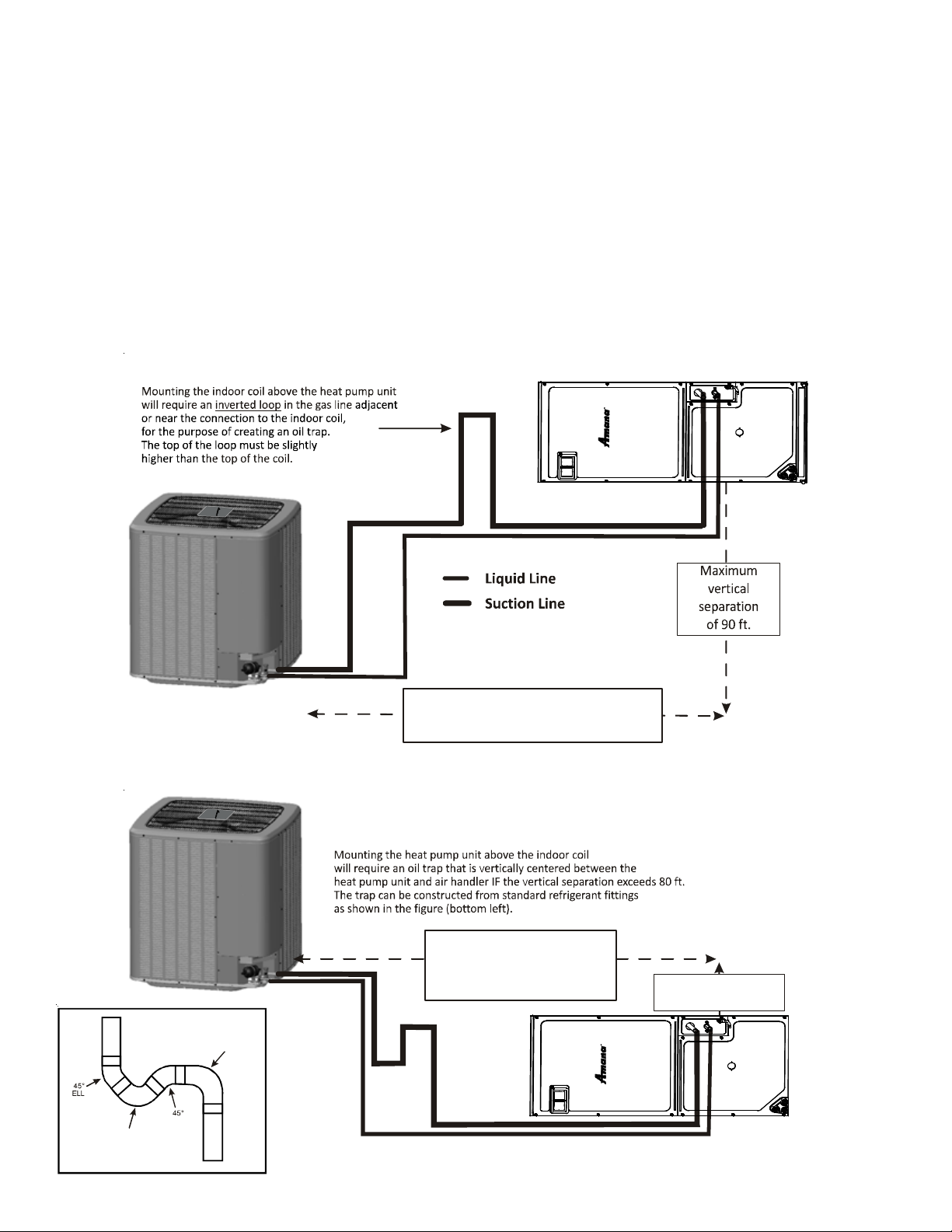
Heat Pump BEL OW Indoor Coil
Insulation is necessary to prevent condensation from forming
and dropping from the gas line. Armflex or satisfactory equivalent with 3/8” min. wall thickness is recommended. In severe
conditions (hot, high humidity areas) 1/2” insulation may be required. Insulation must be installed in a manner which protects
tubing and connections from damage and contamination.
Where possible, drain as much residual compressor oil from existing systems, lines, and traps; pay close attention to low areas
where oil may collect. NOTE: If changing refrigerant, the indoor
coil and metering device must be replaced. Only AV**PVC air
handlers or TXV** expansion valves are compatible and have been
manufacturer approved for use with these models. See unit specifications or AHRI for an approved system match.
Oil Trap Construction
SHORT RADIUS
STREET ELL
STREET
Maximum line set
equivalent length of 250 ft*.
The maximum line set actual length is 200 ft.
*Includes pressure losses of any elbow, bends, etc.
Heat Pump ABOVE Indoor Coil
Maximum line set
equivalent length of 250 ft.*
The maximum line set
actual length is 200 ft.
LONG RADIUS
STREET EL L
ELL
*Includes pressure losses of any elbow, bends, etc.
Maximum vertical
separation of 200 ft.
4
Page 5
RECOMMEND ED
INTERCONNECT ING TUB ING (Ft)
Line Set Length
0 - 250' Equivalent
Do NOT make final refrigerant line connection until plugs are
removed from refrigerant tubing.
L
EAK TESTING
(N
ITROGEN OR NITROGEN-TRACED
)
Heat Pump
Unit
& Li n e Diamet er (I n . OD)
Line Type
(Tons) Suct Liq
23/43/8
37/83/8
41 1/83/8
51 1/83/8
R
EFRIGERANT LINE CONNECTIONS
IMPORT ANT
To avoid overheating the service valve, TXV or filter drier
while brazing, wrap the component with a wet rag, or use a
thermal heat trap compound. Be sure to follow the
manufacturer’s instruction when using the heat trap
compound. Note: Remove Schrader valves from service
valves before brazing tubes to the valves. Use a brazing alloy
of 2% minimum silver content. Do not use flux.
Torch heat required to braze tubes of various sizes is
proportional to the size of the tube. Tubes of smaller size
require less heat to bring the tube to brazing temperature
before adding brazing alloy. Applying too much heat to any
tube can melt the tube. Service personnel must use the
appropriate heat level for the size of the tube being brazed.
NOTE: The use of a heat shield when brazing is recommended
to avoid burning the serial plate or the finish on the unit.
1. The ends of the refrigerant lines must be cut square,
deburred, cleaned, and be round and free from nicks or
dents. Any other condition increases the chance of a
refrigerant leak.
2. “Sweep” the refrigerant line with nitrogen or inert gas
during brazing to prevent the formation of copper-oxide
inside the refrigerant lines. The FVC oils used in R-410A
applications will clean any copper-oxide present from the
inside of the refrigerant lines and spread it throughout
the system. This may cause a blockage or failure of the
metering device.
3. After brazing, quench the joints with water or a wet cloth
to prevent overheating of the service valve.
4. A bi-flow filter drier is shipped with the unit as a separate
component and must be brazed on by the installer onsite. Ensure the bi-flow filter drier paint finish is intact after
brazing. If the paint of the steel filter drier has been
burned or chipped, repaint or treat with a rust
preventative.
The recommended location of the filter drier is before the
expansion device at the indoor unit.
WARNING
TO
AVOID THE RISK OF FIRE OR EXPLOSION, NEVER USE OXYGEN, HIGH
PRESSURE AIR OR FLAMMABLE GASES FOR LEAK TESTING OF A
REFRIGERATION SYSTEM
.
WARNING
TO
AVOID POSSIBLE EXPLOSION, THE LINE FROM THE NITROGEN
CYLINDER MUST INCLUDE A PRESSURE REGULATOR AND A PRESSURE
RELIEF VALVE
NO MORE THAN
. THE
PRESSURE RELIEF VALVE MUST BE SET TO OPEN AT
150
PSIG
.
To locate leaks, pressure test the system using dry nitrogen or
leak detector fluid per the manufacturer’s recommendation. If
you wish to use a leak detector, charge the system to 10 psi using the appropriate refrigerant then use nitrogen to finish charging the system to working pressure then apply the detector to
suspect areas. If leaks are found, repair them. After repair, re-
peat the pressure test. If no leaks exist, proceed to System Start-
up Procedure.
S
YSTEM START-UP PROCEDURE
GENERAL NOTES:
Adequate refrigerant charge for the matching indoor coil and 15
feet of line set is supplied with the heat pump unit. If liquid line
set exceeds 15 feet in length, refrigerant should be added at 0.6
ounces per foot of liquid line.
NOTICE
V
IOLATION OF
PENALTIES
EPA
REGULATIO NS MAY RESU LT IN FINES OR OTHER
.
NOTICE
ALL
UNITS SHOULD HAVE A HIGH VOLTAGE POWER SUPPLY CONNECTED
HOURS PRIOR TO STARTUP
2
.
WARNING
REFRIGERANT UNDER PRESSURE!
• DO
NOT OVERCHARGE SYSTEM WITH REFRIG ERANT
O NOT OPERATE UNIT IN A VACUUM OR AT NEGATIVE PRESSURE
• D
AILURE TO FOLLOW PROPER PROCEDURES MAY CAUSE PROPERTY
F
DAMAGE, PERSONAL INJURY OR DEATH
.
CAUTION
O
PERATING THE COMPRESSOR WITH THE GAS VALVE CLOSED WILL
CAUSE SERIOUS COMPRESSOR DAMAGE
COVERED BY OUR WARRANTIES
-
SUCH DAMAGE IS NOT
.
.
.
NOTE: Be careful not to kink or dent refrigerant lines. Kinked or
dented lines will cause poor performance or compressor damage.
5
Page 6
CAUTION
USE
REFRIGERANT CERTIFIED TO
MAY CAUSE COMP RESSOR DAMAGE, AND
WARRANTY
REFRIGERANT TO MEET
. M
OST PORTABLE MACHINES CANNOT CLEAN USED
AHRI
AHRI
STANDARDS
STANDARDS
. U
SED REFRIGERANT
IS NOT COVERED UNDER
THE
.
START-UP PROCEDURE DETAIL
Liquid and gas valves on heat pump unit are closed to contain the
charge within the unit. The unit is shipped with the valve stems
closed and caps installed. Do not open valves until the indoor coil
and line set is evacuated.
CAUTION
P
ROLONGED OPERATION AT SUCTION PRESSURES LESS THAN
FOR MORE THAN
SCROLLS AND PERMANENT DAMAGE TO THE SCROLL TIPS, DRIVE
BEARINGS AND INTERNAL SEAL
5
SECONDS WILL RESULT IN OVERHEATING OF THE
.
20
PSIG
E
LECTRICAL CONNECTIONS
WARNING
HIGH VOLTAGE!
D
ISCONNECT
M
ULTIPLE POWER SOURCES MAY BE PRESENT
TO DO SO MAY CAUSE PROPERTY DAMAGE, PERSONAL
INJURY OR DEATH DUE TO ELECTRIC SHOCK
MUST CONFO RM WITH
CODES
EQUIPM EN T PERFORMANCE, EQUIPM EN T DAMAGE OR
FIRE
.
TO
AVOID THE RISK OF FIRE OR EQUIPM EN T DAMAGE, USE COPPER
CONDUCTORS
ALL
POWER BEFORE SERVICING
NEC OR CEC
. U
NDERSIZED WIRES COUL D CAUSE POOR
AND ALL LOCAL
WARNING
.
. W
.
. F
AILURE
IRING
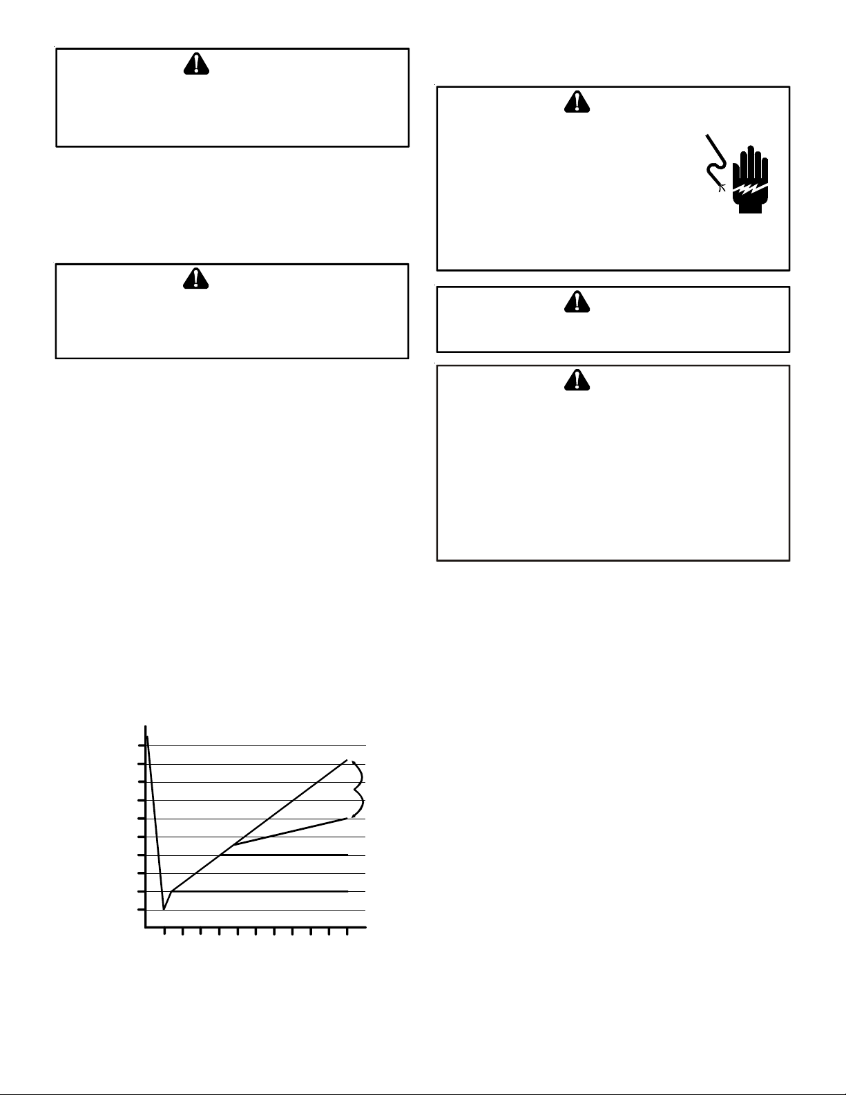
1. Connect the vacuum pump with 250 micron capability to
the service valves.
2. Evacuate the system to 250 microns or less using gas and
liquid service valves. Using both valves is necessary as
some compressors create a mechanical seal separating the
sides of the system.
3. Close pump valve and hold vacuum for 10 minutes.
Typically pressure will rise during this period.
• If the pressure rises to 1000 microns or less and remains
steady the system is considered leak-free; proceed to
start-up.
• If pressure rises above 1000 microns but holds steady
below 2000 microns, moisture and/or noncondensibles
may be present or the system may have a small leak.
Return to step 2: If the same result is encountered check
for leaks as previously indicated and repair as necessary
then repeat evacuation.
• If pressure rises above 2000 microns, a leak is present.
Check for leaks as previously indicated and repair as
necessary then repeat evacuation.
5000
4500
4000
3500
3000
2500
2000
VACUUM IN MICRONS
1500
1000
500
0 1 2 3 4 5 6 7 8 9
CONDENSIBLES OR SMALL
LEAK PRESENT
NO LEAKS
NO CONDE NSIBLES
MINUT ES
LEAK(S)
PRESENT
10
CAUTION
GROUNDIN G R EQUIRED!
LWAYS INSPECT AND USE PROPER SERVICE TOOLS
A
INSPECTION OR IMPROPER TOOLS MAY CAUSE EQUIPMENT DAMAGE OR
PERSONAL INJURY
RECONNECTED BEFORE INSTALLING OR SERVICING
COMPONENTS OF THIS UNIT MAY CONDUCT ELECTRICAL CURRENT
THESE ARE GROUNDED
OF GROUNDING WIRES, SCREWS, STRAPS, CLIPS, NUTS OR WASHERS
USED TO COMPLETE THE GROUND
ORIGINAL POSITION AND PROPERLY FASTENED
. ALL
DISCONNECTED GROUNDING DEVICES
. IF
SERVICING THE UNIT, ANY DISCONNECTION
MUST BE
. L
ACK OF
MUST BE
. M
ULTIPLE
RETURNED TO THEIR
.
;
The heat pump unit rating plate lists pertinent electrical data
necessary for proper electrical service and overcurrent protection. Wires should be sized to limit voltage drop to 2% (max.)
from the main breaker or fuse panel to the condensing unit.
Consult the NEC, CEC, and all local codes to determine the correct wire gauge and length.
Local codes often require a disconnect switch located near the
unit; do not install the switch on the unit. Refer to the installation instructions supplied with the indoor furnace/air handler
for specific wiring connections and indoor unit configuration.
OVERCURRENT PROTECTION
The inverter control system software provides sufficient time
delay to protect from overcurrent conditions and permit the compressor and fan motors to adjust their rotational speed.
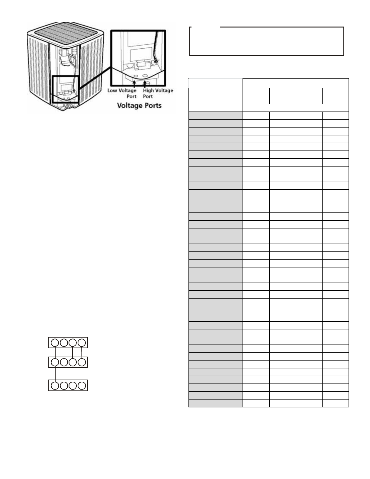
HIGH VOLTAGE CONNECTIONS
Route power supply and ground wires through the high voltage
port and terminate in accordance with the wiring diagram provided inside the control panel cover.
LOW VOLTAGE CONNECTIONS
The unit is designed to work as part of a fully communicating
HVAC system, utilizing a ComfortNet™ CTK04 thermostat,
ComfortNet compatible indoor unit, and up to four wires. Route
control wires through the low voltage port and terminate in accordance with the wiring diagram provided inside the control
panel cover.
6
Page 7
A
NOTICE
T
OTAL REFRIGERANT
F
ACTORY CHARGE
OF A
CTUAL LINE SET
The following table shows refrigerant amounts for every 5 feet of
line.
=
+ (0.6 OZ./FT. * A
).
DDITIONAL FEET
Unit Tonnage
Voltage Ports
NOTE: The communicating thermostat is able to search and iden-
tify the indoor and outdoor units when power is applied to the
system. Refer to the communicating thermostat’s installation
instruction manual for more information.
Connect low voltage communication wires (1, 2) to low voltage
pigtail provided.
THERMOSTAT WIRING
NOTE: A removable plug connector is provided with the control
to make thermostat wire connections. This plug may be removed,
wire connections made to the plug, and replaced. It is STRONGLY
recommended that you do not connect multiple wires into a
single terminal without mechanically twisting the tips together
with a set of pliers. Failure to do so may result in intermittent
operation.
Typical 18 AWG thermostat wire may be used to wire the system components. However, communications reliability may be
improved by using a high quality, shielded, twisted pair cable for
the data transmission lines. In either case, 250 feet is the maximum length of wire between indoor unit and outdoor unit, or
between indoor unit and thermostat.
TWO-WIRE OUTDOOR, FOUR-WIRE INDOOR WIRING
Low voltage wiring consists of two wires between the indoor
unit and outdoor unit and four wires between the indoor unit
and thermostat. The required wires are data lines 1 and 2, “R”
(24 VAC hot) and “C” (24 VAC common).
12RC
12RC
12RC
CTK04
Thermostat
Compatible
ir Handler/Furnace
Integrated Control Module
Compatible AC/HP
Integrated Control Module
System Wiring
Actual Line Set Length
(ft.)
15 (Factory Charge) 165 272 272 242
20 168 275 275 245
25 171 278 278 248
30 174 281 281 251
35 177 284 284 254
40 180 287 287 257
45 183 290 290 260
50 186 293 293 263
55 189 296 296 266
60 192 299 299 269
65 195 302 302 272
70 198 305 305 275
75 201 308 308 278
80 204 311 311 281
85 207 314 314 284
90 210 317 317 287
95 213 320 320 290
100 216 323 323 293
105 219 326 326 296
110 222 329 329 299
115 225 332 332 302
120 228 335 335 305
125 231 338 338 308
130 234 341 341 311
135 237 344 344 314
140 240 347 347 317
145 243 350 350 320
150 246 353 353 323
155 249 356 356 326
160 252 359 359 329
165 255 362 362 332
170 258 365 365 335
175 261 368 368 338
180 264 371 371 341
185 267 374 374 344
190 270 377 377 347
195 273 380 380 350
200 276 383 383 353
2-Ton 3-Ton 4-Ton 5-Ton
Refrigerant (Oz.)
STEP 1. CALCULATE REFRIGERANT CHARGE BASED ON LINE
SET LENGTH
The heat pump unit is shipped with a predetermined factory
charge level as shown below. For longer line sets greater than
15 feet, add 0.6 ounces of refrigerant per foot.
7
Page 8
STEP 2. CONNECT HEAT PUMP UNIT TO SYSTEM
OPEN THE LIQ UID VALVE FI R S T! IF
OPENED FIRST, OIL FROM THE COMPRESSOR MAY BE DRAWN INTO THE
INDOOR COIL OR
OPERATION OF THE SYSTEM
TXV
RESTRICTING REFRIGERANT FLOW AND AFFECTING
.
THE GAS SERVICE VALVE IS
CAUTION
POSSIBL E REFRIGER AN T LEAK!
TO
AVOID A POSSIBLE REFRIGERANT LEAK, OPEN THE SERVICE VALVES
UNTIL THE TOP OF THE STEM IS
1/8”
FROM THE RETAINER
.
CAUTION
E
NSURE VALVES ARE OPEN AND ADDITIONAL CHARGE IS ADDED PER
CHART BEFORE APPLYING POWER
.
ATTENTION INSTALLER - IMPORTANT NOTICE!
Please read carefully before installing this unit.
When opening valves with retainers, open each valve only until
the top of the stem is 1/8” from the retainer. To avoid loss of
refrigerant, DO NOT apply pressure to the retainer. When opening valves without a retainer, remove service valve cap and insert a hex wrench into the valve stem and back out the stem by
turning the hex wrench counterclockwise. Open the valve until it
contacts the rolled lip of the valve body.
NOTE: Units may utilize ball valves or front seating valves. These
are not back-seating valves. It is not necessary to force the stem
tightly against the rolled lip.
After the refrigerant charge has bled into the system, open the
liquid service valve. The service valve cap is the secondary seal
for the valves and must be properly tightened to prevent leaks.
Make sure cap is clean and apply refrigerant oil to threads and
sealing surface on inside of cap. Tighten cap finger-tight and then
tighten additional 1/6 of a turn to properly seat the sealing surfaces.
Do not introduce liquid refrigerant from the cylinder into the
crankcase of the compressor as this may damage the compressor.
Break vacuum by fully opening liquid and gas base valve.
• For AVZC20, do not install the 24 Volt Transformer that is included with the CTK04 Thermostat in the Heat
Pump Unit; it is not needed.
• Do not attach any wires to the R & C Terminals on the Heat Pump Unit, as they are not needed for inverter unit
setup.
•DATA LINE TERMINALS #1 AND #2 ARE POLARITY SENSITIVE. ONLY THE DATA LINES, 1 AND 2, ARE REQUIRED BETWEEN THE INDOOR AND
OUTDOOR
UNITS.
•DATA LINE TERMINAL #1 FROM OUTDOOR UNIT MUST CONNECT TO TERMINAL #1 ON INDOOR UNIT AND DATA LINE TERMINAL #2 FROM
OUTDOOR
UNIT MUST CONNECT TO TERMINAL #2 ON INDOOR UNIT. VERIFY WIRES ARE NOT REVERSED.
•IT IS STRONGLY RECOMMENDED TO USE WIRE NUTS AT THE INDOOR UNIT WHEN CONNECTING MULTIPLE DATA LINES OR LO W VOLTAGE WIRES
TOGETHER
. IT IS NOT RECOMMENDED TO USE THE TERMINAL BLOCK TO CONNECT TWO OR MORE WIRES.
• Calculate the Liquid Line Set length and weigh in 0.6 ounces per foot of R410A refrigerant for any length over
15 feet.
Or
• Charge by Sub-cooling.
Sub-cooling should be between 7° and 9°F. Allow 10 minutes of running in Charge Mode between each
amount of refrigerant added.
DIPSWITCH FAC TO RY DEFAULT SETTINGS
Switch #
OD DS1
OD DS2
* OD DS 2 s w i tch 1 and 2 bo th must be turned on
during normal operation mode
1 ON CT Communication Enabl ed
2 ON CT Communication Enabl ed
1ON
2ON
Setting Purpose
Cooling Emergency Mode
for Future Use *
Cooling Emergency Mode
for Future Use *
8
Page 9
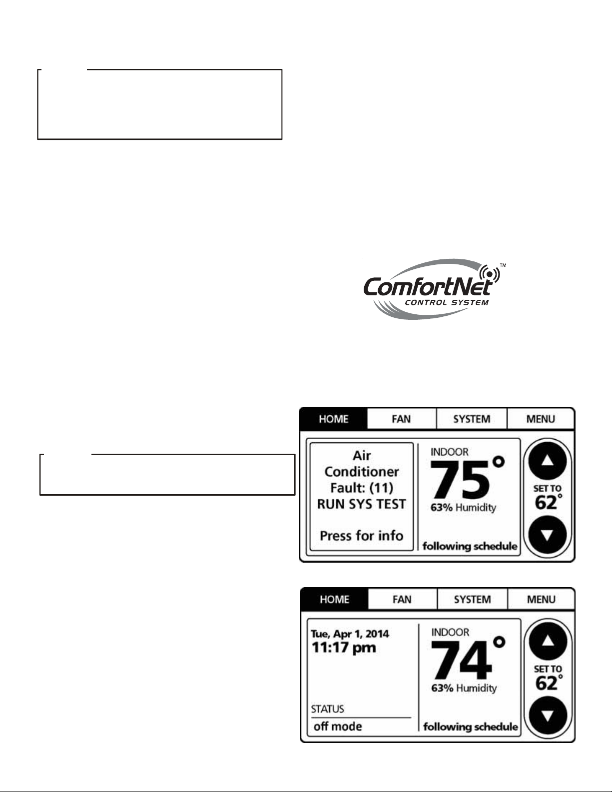
STEP 3. SYSTEM START-UP TEST
NOTICE
ON
INITIAL POWER START-UP, THE OUTDOOR UNIT WILL DISPLAY CODE
E11,
SIGNALING THAT INITIAL
THE COMFORTNET™ SETUP SCREEN TO ENTER APPLICATION-UNIQUE
INFORMATION
DETAILED INFORMATION
. SEE C
A system test is now required to check the equipment
settings and functionality. Once selected, it checks the
equipment for approximately 5 - 15 minutes. System test
may exceed 15 minutes if there is an error. Refer to
the Troubleshooting section.
Before starting the SYSTEM TEST, turn off the electric heater
or gas furnace.
1. Ensure the thermostat is installed.
SYSTEM
OMFORTNET THERMOSTAT MANUAL FOR
TEST MUST BE RUN
. F
.
OLLOW
2. Apply power to outdoor and indoor units.
3. Start-up.
After the application information is entered,
the initial system test must be run.
NOTICE
FOR
INVERTER
TRANSFORMER
The HOME screen will be displayed showing
information similar to one of the adjacent screens.
Select MENU.
NOTE: Either screen may be displayed.
SYSTEM TEST must be run for all installations.
System will not operate without a completed initial
SYSTEM TEST.
NOTE: Ensure the thermostat is in OFF mode.
H/P
SYSTEM USING COMFORTNET, DO
.
NOT
INSTALL A
9
Page 10
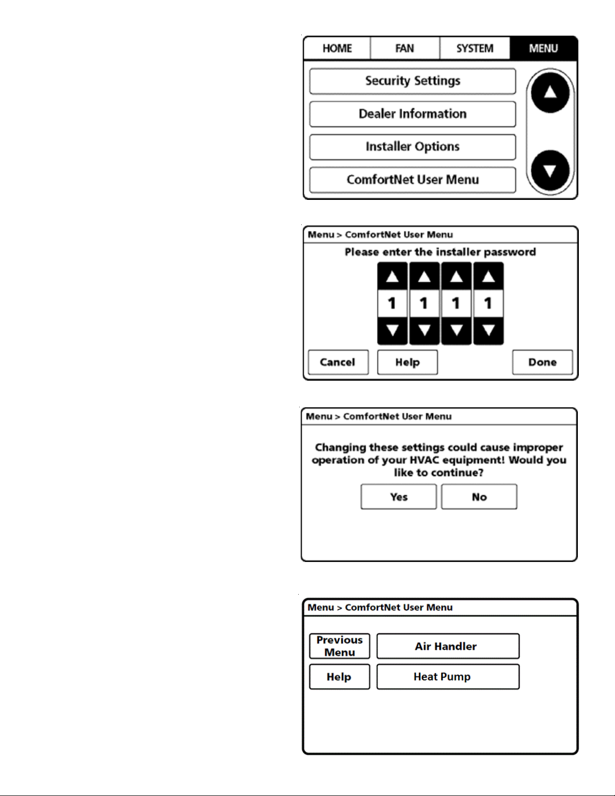
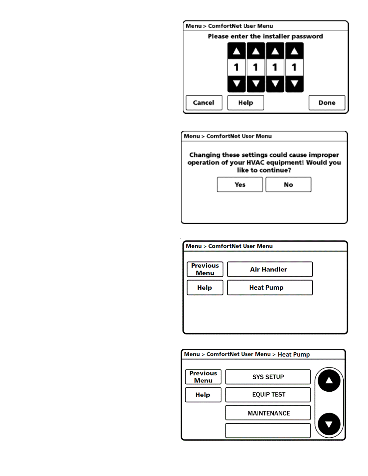
4. From the MENU screen, scroll down and select
COMFORTNET™ USER MENU.
5. Enter Installer password. (The password is the Date
Code located on the thermostat and is available by
entering the EQUIPMENT STATUS menu and
scrolling to the bottom.)
6. Select YES to continue.
7. From the ComfortNet USER MENU,
select HEAT PUMP.
NOTE: Screen may show air handler
or furnace depending on the type of system installed.
10
Page 11
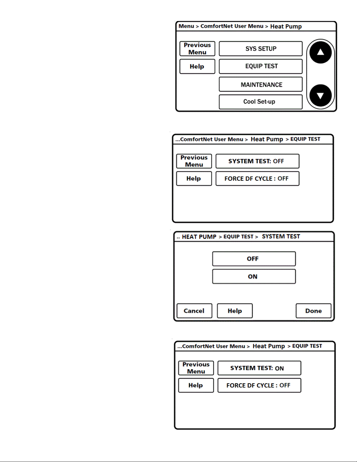
8. Next, scroll down and select EQUIP TEST.
9. Select SYSTEM TEST.
10. Select ON to run the SYSTEM TEST.
Press DONE to initiate test.
11. Allow the system test to run for its duration
(5-15 minutes). EQUIP TEST SCREEN will
show the system test is ON once selected.
System test will operate the outdoor unit and the
indoor unit through a series of startup tests.
Please proceed to the next step and allow for
startup tests to complete. Do not interrupt power
to outdoor unit, indoor unit, or thermostat
during system test.
11
Page 12
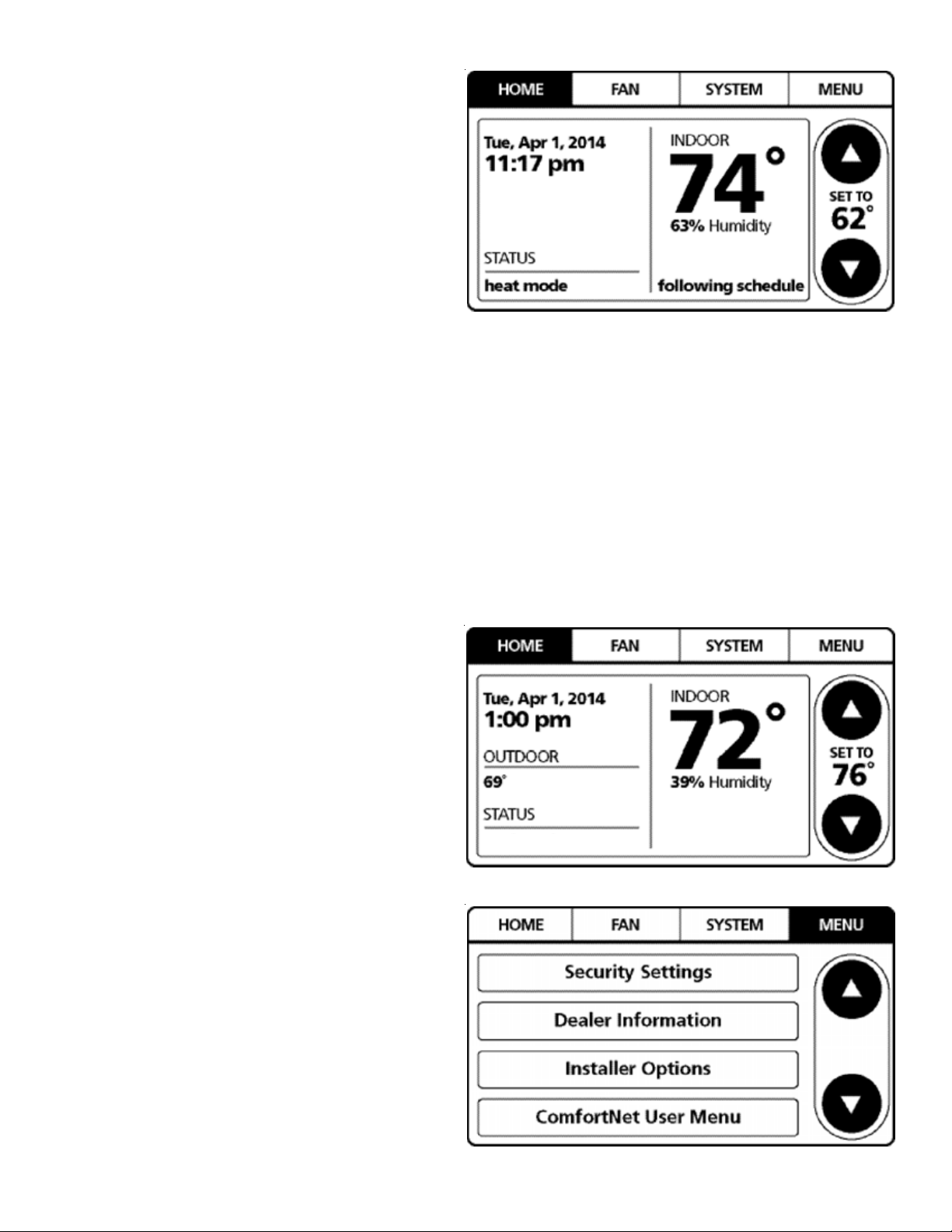
12. Press Previous Menu button and navigate to
HOME screen and allow test to finish. The display
similar to the one at the right will be displayed
after SYSTEM TEST completes. Test is complete
only when CODE 11 notice clears from BOTH the
thermostat display AND the seven segment LED
display on the outdoor unit. Please wait for test to
complete and for both codes to clear.
STEP 4. SET THERMOSTAT TO CHARGE MODE
Please follow the following sequence to enter CHARGE MODE.
CHARGE mode allows for charging of the system. System operates for a duration of approximately one hour while the
equipment runs at full capacity. After one hour, the CHARGE
MODE ends and the system resumes normal thermostat
operation.
Before starting the CHARGE MODE, turn off the electric
heater or gas furnace.
1. On the HOME screen, select MENU.
NOTE: Set COOL or HEAT MODE to OFF before starting
CHARGE MODE.
2. From the MENU screen, select
COMFORTNET™ USER MENU.
off
12
Page 13
3. Enter Installer password. (The password
is the Date Code located on the thermostat
and is available by entering the
EQUIPMENT STATUS menu and
scrolling to the bottom).
4. Select YES to continue.
5. Select HEAT PUMP.
6. Select MAINTENANCE.
13
Page 14
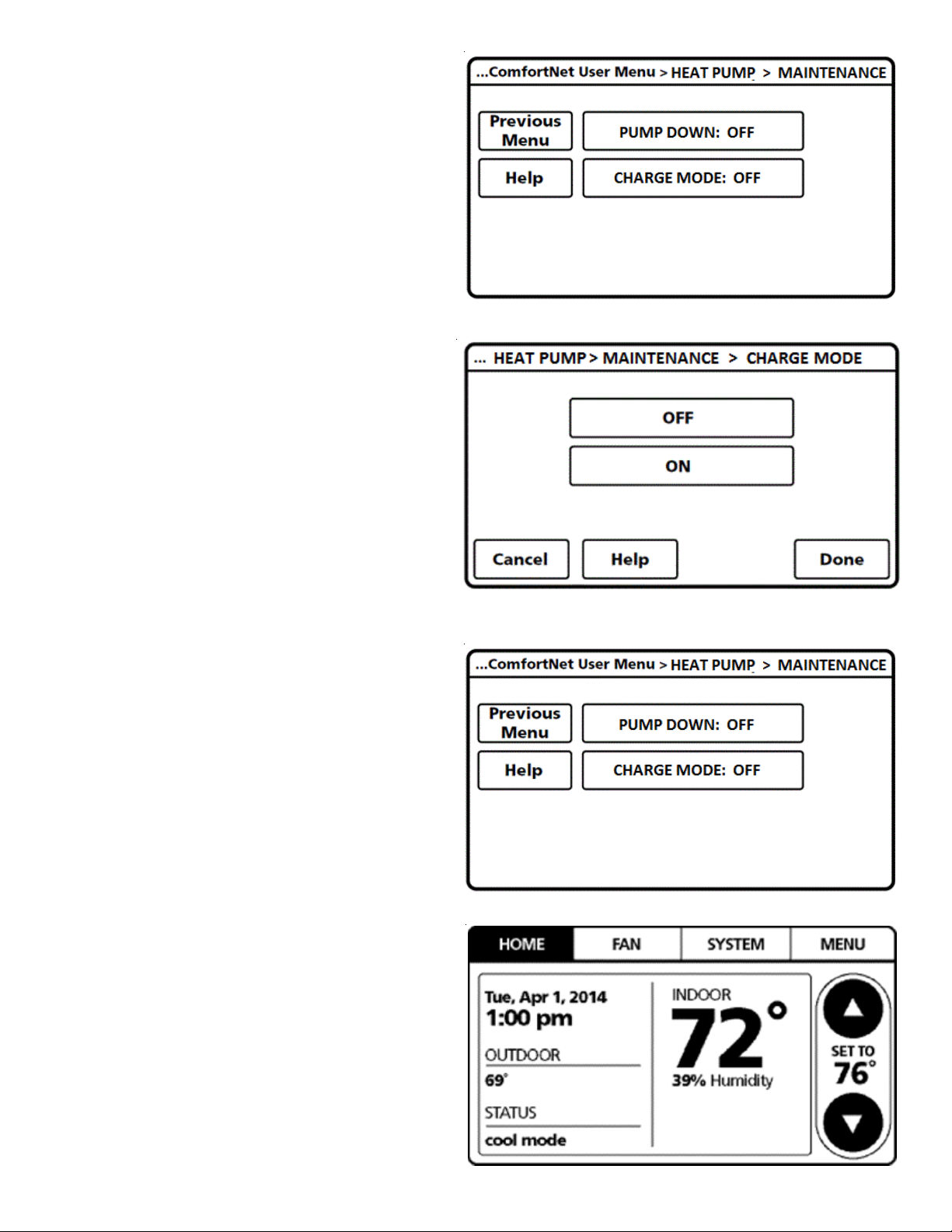
7. Select CHARGE MODE.
8. Select ON. Press DONE to initiate CHARGE mode. (System
will then run for 1 hour and either return to cooling or
heating mode depending on the mode thermostat is set
at COOL or HEAT, or stop if the thermostat is set for FAN
only mode.)
If charging is not complete after 1 hour, repeat
7. and 8.
Refer to STEP 5 and STEP 6 for refrigerant charge
level adjustment.
9. To terminate CHARGE MODE, select CHARGE
mode screen again. Press OFF. Press DONE to
terminate CHARGE MODE.
10. Once CHARGE MODE is complete and has been
terminated, navigate to HOME screen. Enter
normal operation with temperature offset or thermostat
schedule, as desired.
14
Page 15
STEP 5. ADJUST REFRIGERANT LEVEL
Using service equipment, add or recover refrigerant according to
the calculation in Step 1. Allow system to stabilize for 10 minutes
after adjusting charge level.
STEP 6. MEASURE SUBCOOLING TO VERIFY PROPER CHARGE
NOTE: Charging equipment must use dedicated PVE oil gauges
and hoses.
1. Purge gauge lines.
2. Connect service gauge manifold to base valve service ports.
3. Convert the liquid pressure to temperature using a
temperature/pressure chart.
4. Temporarily install a thermometer on the liquid line at
the liquid line service valve.
a. Ensure the thermometer makes adequate contact
and is insulated for best possible readings.
5. Subtract the liquid line temperature from the converted
liquid pressure to determine subcooling.
6. Before starting the Subcooling adjustment, make sure the
outdoor ambient temperature is in a below range and the
unit is operating at 100% capacity.
SUBCOOLING = (SA T. LIQUID TEMP .) - (LIQUID LINE
TEMP.)
SUPERHEA T = ( SUCT. LINE TEMP .) - (S AT . SUCT. TEMP .)
e. If subcooling and superheat are high, adjust the TXV
valve to 7 to 9°F superheat, then check subcooling.
f. If subcooling is high and superheat is 7 to 9°F, remove
charge to lower the subcooling to 7 to 9°F, then check
superheat.
g. If subcooling is high and superheat is low, adjust the
TXV valve to 7 to 9°F superheat and remove charge to
low the subcooling to 7 to 9°F.
h. If subcooling is 7 to 9°F and superheat is low, adjust the
TXV valve to 7 to 9°F superheat and remove charge to
lower the subcooling 7 to 9°F, then check the superheat.
NOTE: Not more than 0.5 lb. (8 Oz.) of refrigerant must
be added to the system in order to achieve the target
subcooling. It is recommended to add 4 oz. refrigerant
each time and try adjusting the TXV and let the system
stabilize.
NOTICE
C
HECK THE SCHRADER PORTS FOR LEAKS AND TIGHTEN VALVE CORES, IF
NECESSARY
. I
NSTALL CAPS FINGER-TIGHT
.
NOTICE
DO NOT
THERE IS A GROSS UNDERCHARGE
ADJUST THE CHARGE BASED ON SUCTION PRESSURE UNLESS
.
Chargi ng Tabl e
OD Ambie nt Tem p
(degF)
Subcooling
(degF)
Note: Subcooling information is valid only while the unit is operating
at 100% capacity or 100% of compressor speed in CHARGE MODE.
Compressor speed is displayed under STATUS menu in the thermostat.
< 65 °F 65°F to 105°F > 105 °F
Weigh in
Charge
7°F to 9°F
Weigh in
Charge
7. The system subcooling should be 7 to 9°F. If not in that
range, adjust subcooling and superheat according to the
following procedure.
a. If subcooling and superheat are low, adjust TXV to 7 to
9°F superheat, then check subcooling.
NOTE: To adjust superheat, turn the valve stem clockwise
to increase and counter clockwise to decrease.
b. If subcooling is low and superheat is 7 to 9°F, add charge
to rise subcooling to 7 to 9°F, then check superheat.
c. If subcooling is low and superheat is high, add charge to
rise subcooling to 7 to 9°F, then check superheat.
d. If subcooling is 7 to 9°F and superheat is high, adjust
the TXV valve to 7 to 9°F superheat, then check
subcooling.
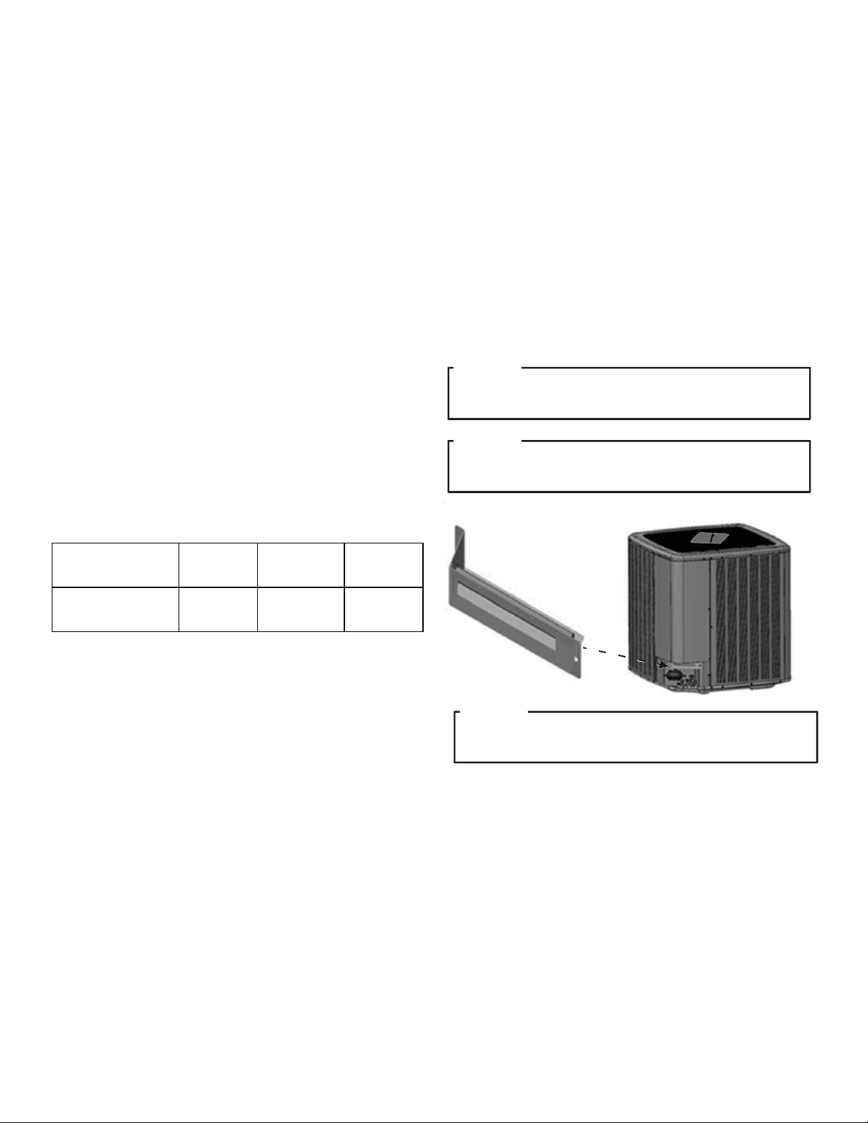
Rain
Shield
NOTICE
IF
THE RAIN SHIELD WAS REMOVED DURING THE INSTALLATION
PROCESS, BE SURE TO RE-INSTALL IT AFTER CHARGING THE UNIT
.
HEAT PUMP WITH OUTDOOR TEMPERATURE LOCKOUTS
It is recommended to set the outdoor temperature lockouts
during the initial thermostat set up. This will enable the compressor to be turned off and switch heating source from refrigeration to auxiliary/secondary heating under low ambient conditions.
15
Page 16

Backup heat lockout temperature will enable auxiliary/secondary heating to be turned on when outdoor temperature is
much higher than indoor temperature, compressor might stop
operating under this circumstance.
Line Set Length Range
(feet)
0 to 100 15
100 to 200 20
Compres sor Lo ck o ut T emperatu re
(°F)
In order to access temperature, the compressor lockout and
the backup heat lockout, press MENU and scroll down to
press INSTALLER OPTIONS. Enter the date code (password)
when prompted. Choose VIEW / EDIT CURRENT SETUP and
COMPRESSOR LOCKOUT / BALANCE POINT will be under
HEAT / COOL CONTROL OPTIONS. For more information
please refer to COMFORTNET™ CTK04 Communicating Thermostat SYSTEM INSTALLATION GUIDE.
BOOST MODE
BOOST MODE enables the system to operate at a higher compressor speed than rated maximum compressor speed and
satisfy the structural load more effectively during higher
ambient outdoor conditions. BOOST MODE is initiated by
an outdoor temperature sensor located in the outdoor unit.
Please note that outdoor equipment operational sound levels may increase while the equipment is running in BOOST
MODE. Disabling BOOST MODE will provide the quietest and
most efficient operation.
NOTE: BOOST MODE is applicable only for AVZC200**1AB
or later revision. BOOST MODE performance is most effective when paired with an electronic expansion valve enabled
indoor unit.
BOOST MODE is ON by default and is activated when the
outdoor temperature reaches 105°F. BOOST MODE can be
disabled and enabled and the activation temperature adjusted in the BOOST TEMP menu using the following procedure:
SATURATED SUCTI ON PRESS U RE
TEMPERATURE CHART
SUCTION PRESSURE LIQUID PRESSURE
PSIG PSIG
50 1 200 70
52 3 210 73
54 4 220 76
56 6 225 78
58 7 235 80
60 8 245 83
62 10 255 85
64 11 265 88
66 13 275 90
68 14 285 92
70 15 295 95
72 16 305 97
74 17 325 101
76 19 355 108
78 20 375 112
80 21 405 118
85 24 415 119
90 26 425 121
95 29 435 123
100 31 445 125
110 36 475 130
120 41 500 134
130 45 525 138
140 49 550 142
150 53 575 145
160 56 600 149
170 60 625 152
R-410A
°F
SATURATED L IQUID P RES SURE
TEMPERATURE CHART
R-410A
°F
1. On the CTK04 HOME screen, select MENU.
2. From the MENU screen, select COMFORTNET™ USER
MENU.
16
Page 17

3. Enter Installer password. (The password is the Date
Code located on the thermostat and is available by
entering the EQUIPMENT STATUS menu and scrolling
to the bottom).
4. Select YES to continue.
5. Select HEAT PUMP.
6. Select SYS SETUP.
17
COOL SET-UP
Page 18

7. BOOST MD turns BOOST MODE OFF or ON. BOOST
MODE is ON by default.
...Heat Pump > SYS SETUP > BOOST MD
8. BOOST TEMP adjusts the activation temperature
from 70°F to 105°F. “Always ON” option is also
available to permanently engage BOOST MODE.
Factory default is 105°F.
105F
...Heat Pump > SYS SETUP > BOOST TEMP
18
Page 19

9. Once satisfied with BOOST MODE adjustments, navigate
to the HOME screen by selecting the Previous Menu
button three times then selecting HOME.
DEHUMIDIFICATION
The thermostat reads the indoor humidity level from the CTK04
and allows the user to set a dehumidification target based on
these settings. The thermostat controls the humidity level of
the conditioned space using the cooling system. Dehumidification is engaged whenever a cooling demand is present and
structural humidity levels are above the target level. When this
condition exists, the circulating fan output is reduced, increasing system run time, over cooling the evaporator coil and ultimately removing more humidity from the structure than if only
in cooling mode. The CTK04 also allows for an additional
overcooling limit setting from 0°F to 3°F setup through the
Installer Option menu (directions following). This allows the
cooling system to further reduce humidity by lowering the temperature up to 3°F below the cooling setpoint in an attempt to
better achieve desired humidity levels.
By default, dehumidification needs to be turned ON at the thermostat via the Dehumidification Equipment menu. Dehumidification can be activated at the original equipment setup by
selecting the A/C with Low Speed Fan button in the Dehumidification Menu. Availability can be verified by pressing MENU
on the home screen. Scroll down and if a Dehumidification
button is present, dehumidification is activated.
If Dehumidification is not available in the menu then it must
be enabled through the Installer Options menu. Use the following procedure to enable and disable dehumidification:
1. On the CTK04 HOME screen select MENU.
2. From the MENU screen, scroll down and select Installer
Options.
3. Enter installer password if known.
a. The password is the thermostat date code and can
be obtained by selecting the red Cancel button and
selecting the Dealer Information button.
b. Once recorded, click the green OK button and re-
turn to the previous step.
4. Select YES to continue.
5. Select View / Edit Current Setup.
6. Scroll down and select Dehumidification.
7. Once open select Dehumidification Equipment: None.
8. From the Dehumidification Menu select A/C with Low Speed
Fan and click the green Done button.
9. Additional Dehumidification operational options can be
selected in the resulting window.
10. Once satisfied with the selection, navigate to the HOME
screen by selecting the Done button and selecting Yes to
verify the changes.
11. Select Previous Menu, then the HOME to return to the
main menu.
DEHUMIDIFICATION TIPS
For effective dehumidification operation:
• Ensure “Dehum” is ON through the Installer Options
menu and/or in the ComfortNet User Menu (COOL
SETUP).
- If ON, the Dehumidification menu should be visible in
the main menu.
• Verify the cooling airflow profile is set to “Profile D”.
- See the Cool Set-up section of the Installation Manual
for complete airflow profile details.
- By default, “Dehum” is ON and the cooling airflow pro-
file is set to “Profile D”.
• For additional dehumidification control, airflow settings
are field adjustable and can be fine-tuned to a value that
is comfortable for the application from a range of +15%
to -15%.
- See the Heat Pump Advanced Feature Menu section
of the Installation Manual for more detail.
19
Page 20

COMFORTNET™ SYSTEM
OVERVIEW
A ComfortNet inverter heating and air conditioning system uses
an indoor unit, outdoor unit and thermostat which digitally communicate with one another via a two-way communications path.
The thermostat sends commands to the indoor and outdoor
units. The thermostat may request and receive information from
both the indoor and outdoor units. This information may be displayed on the CTK04 thermostat. The indoor and outdoor units
also interact with one another. The outdoor unit may send commands to or request information from the indoor unit. This twoway digital communications between the thermostat and subsystems (indoor/outdoor unit) and between subsystems is the
key to unlocking the benefits and features of the ComfortNet
system.
Two-way digital communications is accomplished using only two
wires. The thermostat needs 24 VAC for power. 4 wires between
the indoor unit and thermostat plus two wires between the indoor unit and outdoor unit are all that are required to operate
the system.
COMFORTNET SYSTEM ADVANCED FEATURES
The ComfortNet™ system permits access to additional system
information, advanced set-up features, and advanced diagnostic/troubleshooting features. These advanced features are orga-
nized into a menu structure. See the HEAT PUMP ADVANCED
FEATURES MENU section for the menu layout.
DIRECTIONS TO HEAT PUMP ADVANCED FEATURE MENUS
Press MENU, scroll down and press COMFORTNET USER MENU.
Enter the date code (password) when prompted. The date code is
printed on the back of the thermostat; or press MENU > EQUIP-
MENT STATUS and scroll down to find the date code. After you
enter the password, select COMFORTNET USER MENU, answer YES
to the following menu and select HEAT PUMP to view the system
menus.
DIAGNOSTICS
The heat pump’s diagnostics menu provides access to the most
recent faults. The six most recent faults are displayed on the first
screen. Six additional faults are displayed under fault history.
Faults are stored in order from most recent to least recent. Any
consecutively repeated fault is stored a maximum of three times.
Example: A leak in the system, low refrigerant charge or an incompletely open stop valve can cause the unit to flash error code E15.
This error code suggests that the unit is experiencing operation at
low pressure. The control will only store this fault the first three
consecutive times the fault occurs.
NOTE: It is highly recommended that the fault list be cleared after
performing maintenance or servicing the system.
STATUS
This menu displays information about the systems current status.
This menu can be utilized to confirm correct functionality of the
equipment and for troubleshooting purposes. The following items
will be displayed:
TS Tim e Stamp
MD Mode
CRM Compressor Reduction Mode
RAD Requested and Actual % Demand
RAF Requested and Reported ID CFM
ATOF* Outdoor Air Temperature and Outdoor Fan RPM
DCT Discharge Temperature and Outdoor Coil Temperature
DLT Defrost Sensor and Outdoor Liquid Temperature
PSDST** Pressure Sensor and Outdoor Suction Temperature
* Only for AVZC200**1AB or later revision.
ATPRM is shown in AVZC200**1AA revision.
** Only for AVZC200**1AB or later revision.
PSD is shown in AVZC200**1AA revision.
Time Stamp: Provides compressor run time in hours.
Mode: Current system operational mode (COOLING, HEATING,
COOLING STARTUP, HEATING STARTUP, OIL RETURN, DEFROST,
STOP).
Compressor Reduction Mode: The compressor is running at a
speed lower than what is requested, based on the cooling load.
Requested and Actual % Demand: Compares the requested cool-
ing demand to what the equipment is providing. For steady state
operation, these numbers should match.
Requested and Reported ID CFM: Compares the requested in-
door airflow to what the indoor equipment has reported.
Outdoor Air Temperature and Outdoor Fan RPM: Displays the
outdoor air temperature as well as the outdoor fan speed (RPM).
Discharge Temperature and Outdoor Coil Temperature: Displays
the discharge temperature and outdoor coil temperature sensor
readings.
Defrost Sensor and Outdoor Liquid Temperature: Displays de-
frost sensor and outdoor liquid temperature sensor readings.
Pressure Sensor: Displays the pressure sensor reading.
20
Page 21

NOTE: Oil Return Mode: In order to properly return oil to the
compressor, compressor speed may periodically adjust to assist
oil circulation.
OFF
OFF
EQUIPMENT TEST
The mandatory system verification test is enabled from this menu,
which enables a functional check of the equipment, in addition
to ensuring proper stop valve position. The heat pump unit can
be set to manual defrost from this menu by selecting FORCE DF
CYCLE.
MAINTENANCE
Pump down and charge modes can be enabled within this menu.
COOL SET-UP
This menu allows for the adjustment of several cooling performance variables. Cool Airflow Trim (range from -15% to +15% in
3% increments), Cool Airflow Profiles, Cool Fan ON Delay, Cool
Fan OFF Delay and Dehumidification Select (enable or disable
dehumidification) can be adjusted in this menu. You can also
reset this entire menu to factory default settings. See the following images showing the four cooling airflow profiles.
• Profile A provides only an OFF delay of one (1) minute at 100%
of the cooling demand airflow.
OFF
• Profile B ramps up to full cooling demand airflow by first
stepping up to 50% of the full demand for 30 seconds. The
motor then ramps to 100% of the required airflow. A one (1)
minute OFF delay at 100% of the cooling airflow.
OFF
50% CFM
1/2 min
100% CFM 100% CFM
1 min
100% CFM
100% CFM
OFF
OFF
1 min
Airflow Tables
COOL RUN VALUES
Depending on the system configuration, adjusting the maximum
compressor RPS (revolutions per second) may be required. Necessary adjustments to the maximum compressor RPS are made
through the following sub-menus.
M
AXIMUM COMPRESSOR RPS RANGE FOR COOLING
Select the range that your maximum compressor RPS falls
within.
MAXIMUM COMPRESSOR RPS SELECTION FOR COOLING
Within the selected range, choose the specific maximum compressor RPS for the system configuration.
HEAT SET-UP
This menu allows for the adjustment of several heating performance variables. Heat Airflow trim (range from -15% to +15% in
3% increments), Heat Fan ON Delay, Heat Fan OFF Delay and
timed Defrost interval can be adjusted in this menu. Time interval of 30, 60, 90 and 120 minutes between two defrost cycles
can be set to suit the weather conditions and performance of
the unit.
HEAT RUN VALUES
Similar to cooling mode, the maximum compressor speed RPS
(revolutions per second) can be adjusted for heating mode under this menu.
MAXIMUM COMPRESSOR RPS RANGE FOR HEATING
Select the range that your maximum compressor RPS falls
within.
MAXIMUM COMPRESSOR RPS SELECTION FOR HEATING
Within the selected range, choose the specific maximum compressor RPS for the system configuration.
• Profile C ramps up to 82% of the full cooling demand airflow
and operates there for approximately 7 1/2 minutes. The
motor then steps up to the full demand airflow. Profile C also
has a one (1) minute 100% OFF delay.
OFF
100% CFM
• Profile D (default) ramps up to 50% of the demand for 1/2
minute, then ramps to 82% of the full cooling demand airflow
and operates there for approximately 7 1/2 minutes. The
motor then steps up to the full demand airflow. Profile D has a
1/2 minute at 50% airflow OFF delay.
OFF
21
Page 22

H
EAT PUMP ADVANCED FEATURE MENU
DIAGNOSTICS
SUBMENU ITEM
Clear Faults NO or YES Selecting "YES" clears the fault history.
Fault 1 Most recent HP f ault
Fault 2 2nd most recent HP fault
Fault 3 3rd most recent HP fault
Fault 4 4th mo st recent HP fault
Fault 5 5th mo st recent HP fault
Fault 6 6th mo st recent HP fault
SUBMENU ITEM COMMENTS
Time Stamp (TS)
Mode (MD)
Co mpressor Reductio n Mode (C RM)
Requested and Actual % Demand (RAD)
INDICATION/USER
MODIFIABLE OPTIONS
STATUS
Provides co mpresso r run time in ho urs.
Current system operation mode (COOLING, COOLING STARTUP, HEATING, HEATING STARTUP, DEFROST,
OIL RETURN, STOP).
Displays ON o r OFF status. ON indicates that the reduction mode is operating and the compressor is
running at a lower speed than the cooling load would normally require.
Displays a 0-100% value, based on a ratio of the requested cooling demand to what the system is actually
providing.
COMMENTS
Requested and Reported ID C FM (RAF)
Outdoo r Air Temperature and Outdoor Fan
RPM (ATOF*)
Discharge Temperature and Outdoor Coil
Temperature (DCT)
Def ro st sensor and Outdo or Liquid
Temperature (DLT)
Pressure Sensor (PSDST**)
* Only for AVZC200**1AB or later revision. ATPRM is shown in AVZC200**1AA revision.
** Only for AVZC20**1AB or later revision. PSD is shown in AVZC200**1AA revision.
Co mpares the requested indoor a irflo w to what the indo or equipment has repo rted.
Displays the outdoor air temperature as well as the outdoor fan speed (RPM).
Displays the discharge temperature and outdoor coil temperature sensor readings.
Displays the def rost temperature sensor and o utdo or liquid tempera ture sensor reading.
Displays the pressure sensor reading which is taken slightly upstream of the suction accumulator.
22
Page 23

H
EAT PUMP ADVANCED FEATURE MENU
SYSTEM SETUP (SYS SETUP)
SUBMENU ITEM USER MODIFIABLE OPTIONS COMMENTS
Reset System Setup Options to Facto ry
Defaults
SET MAX CURRENT N/A Future use.
VERTICAL RISE
BOOST MODE (BOOST MD) ON or OFF
BOOST MODE TEMPERATURE
(BOO ST TEMP)
SUBMENU ITEM
System Verification Test (SYSTEM TEST) ON or OFF
NO or YES Selecting "YES" resets this menu to factory default settings.
If the outdoor & indoor units are within +/- 15 ft. vertical distance,
Same Level, Outdoor Lower, or
Indoor Lower
Always ON, 70, 75, 80, 85,
90, 95, 100, 105F
EQUIPMENT TEST (EQUIP TEST)
INDICATION/USER
MODIFIABLE OPTIONS
select SAME LEVEL. If the outdoor unit is more than 15 ft. below the
indoor unit, select OUTDOOR LOWER. If the outdoor unit is more than
15 ft. above the indo or unit, select INDOOR LOWER.
BOOST MD turns BOOST MODE OFF or ON. BOOST MODE is ON by
default. See BOOST MODE section of this ma nual for more details.
BOOST TEMP adjusts the activation temperature from 70°F to 105°F.
An "Always ON" option is also available to permanently engage BOOST
MODE.
COMMENTS
System Verification Test must be run after installation. This is
approximately a 5-15 minute test. If the thermostat is set to COOL
mode, the system will enter CHARGE mode upon completion,
otherwise it will stop.
Force Def rost Cycle (FORCE DF CYCLE) ON or OFF This will make the unit run in defrost mode.
SYSTEM MAINTENANCE
SUBMENU ITEM USER MODIFIABLE OPTIONS COMMENTS
Ente r PU MP DOWN Mode. This pro cedure runs the equipment for
PUMP DOWN ON or OFF
CHARGE MODE ON or OFF
NOTE: BOOST MODE is applicable only for AVZC200**1AB or later revision.
approximately 15 minutes and allows accumulation of refrigerant at
the o utdoo r unit for purposes of removing & replacing the indoor unit
or outdoor unit.
Enter Charging Mode. This allows for a steady system operation for a
duration of approximately 1 hour to allow for refrigerant charging of
the system via the suction charge port. The system will stop af ter
completion.
23
Page 24

H
EAT PUMP ADVANCED FEATURE MENU
COOL SETUP
SUBMENU ITEM USER MODIFIABLE OPTIONS COMMENTS
CL Reset YES or NO Selecting to default factory setting.
Cool Airflow Trim Hi -15% to +15% in 3% increments Selects the cooling airflo w trim amount.
Cool Airflow Trim Int -15% to +15% in 3% increments Selects the cooling airflow trim amount.
Cool Airflow Trim Low -15% to +15% in 3% increments Selects the cooling airflow trim amount.
Cool Airflow Profile A, B, C, or D Selects the cooling airflow profile.
Cool ON Delay 5, 10, 20, 30 seconds Selects the indoor blower ON delay.
Cool OFF Delay 30, 60, 90, 120 seconds Selects the indoor blower OFF delay.
Dehumidif ic atio n Selec t ON o r OFF Sele cting OFF disables dehumidif icatio n; selecting ON
enables dehumidificatio n.
SET COOLING RUN VALUES (CL RUN VALUES)
SUBMENU ITEM USER MODIFIABLE OPTIONS COMMENTS
Maximum Compressor RPS Range for Cooling (COOL
RPS RANGE)
Maximum Compressor RPS Selection for C ooling
(COOL RPS SELECT)
Five different compressor RPS ranges
will be provided.
10 compressor RPS values will be
provided within the range selected in
the COOL RPS RANGE menu
Select the appropriate range for the installed system
configuration.
Select the appropriate compressor RPS for the installed
system c onfiguration.
HEAT S E T U P
SUBMENU ITEM USER MODIFIABLE OPTIONS COMMENTS
HT Reset YES or NO Selecting to default factory setting.
Heat Airflow Trim Hi -15% to +15% in 3% increments Selects the Heating airflow trim amount.
Heat Airflow Trim Int -15% to +15% in 3% increments Selects the Heating airflow trim amount.
Heat Airflow Trim Low -15% to +15% in 3% increments Selects the Heating airflow trim amount.
Heat ON Delay 5, 10, 15 seconds Selects the indoor blower ON delay.
Heat OFF Delay 30, 50, 70, 90 se conds Selects the indoor blower OFF dela y.
Maximum Defrost Interval 30 mins., 1 hr., 1.5 hrs. & 2 hrs. Se lects time def rost interval
SET HEATING RUN VALUES (HT RUN VALUES)
SUBMENU ITEM USER MODIFIABLE OPTIONS COMMENTS
Maximum Compressor RPS Range for Heating (HEAT
RPS RANGE)
Maximum Compressor RPS Selection for Heating (HEAT
RPS SELECT)
Five different compressor RPS ranges
will be provided.
10 compressor RPS values will be
provided within the range selected in
the HEAT RPS RANGE menu
Select the appropriate range for the installed system
configuration.
Select the appropriate compressor RPS for the installed
system c onfiguration.
24
Page 25

W
IRING DIAGRAM
- 2 TONS
AVZC200241**
HPS)
(
0140R00344-F
MOTOR
THERMI STOR/TEMPERATURE SENSO R
OMPONENT CODE
C
+
HIGH PRESSURE SWITCH
HIGH/ LOW PRESSURE TRA NSDUCER(H/LP T)
DS1/DS2 DIP SWITCH
SEG1-SEG 3 7- SEGMENT DISPLAY
Z1C-Z4 C F ERRITE CORE
TERMINAL
CONNECTOR
NOISELESS EARTH
ELECTRICAL GR OUND
HIGH VOLTAGE
LOW VOLTAGE
HIGH VOLTAGE FIELD
BS1-BS3 PUSH BUTTON SWITCH
RVC REVERSIN G VALVE COIL
M1C COMPRESSO R MOTOR
M1F FAN MOTOR
HP MODELS
W
U
V
COMP RESSOR
TERMINAL ORIENTATION
X12A
-
SHARE DATA
BS3
BS2
BS1
DS1
2
12R
BK
HPS
Z1C
BK
RD
V
X32A
C
UNIT
NOTE 1
X851A
W1Y1Y2
U
L
0
SEE NOTE 4
WH
X52A
OFF
ON
1
R
OO
GY
TO I ND
H/LPT
+
PU
RD
HIGH VOLTAGE!
DISCONNECT ALL POWER BEFORE SERVICING OR INST ALLING THIS
UNIT. MULTIPLE POWER SOURCES MAY BE PRESENT. F AILURE TO
DO SO MAY CAUSE PROPERTY DAMAGE, PERSONAL INJURY OR DEATH.
POWER CON DITI ONER
AMBIENT
RVC
YL BL
BK
BK
TRANSFORMER
24V
1
2
RD
3
208/240 V
ON
OFF
2
DS2
EEV
RING
COLOR
X17A
1
NOTE 1
SEG3
SEG2
SEG1
X21A
X11A
C
C
R
O
L
C
U
I
I
T
I
T
D
O
R
S
E
F
D
I
L
N
I
L
Q
E
U
I
G
E
R
C
D
A
H
S
I
L
N
E
I
GR
M1C
YL
Z4C
W
HR2
HR4
INVERTER BOA RD
X25A
BK
M1F
BK
RD
WH
X108A
HR1 H R3
RD
BK
L1
L2
E1
TAB L E
EC13006-1 (2T) AVZC200241 DZ20VC0241
INVERTER MODEL
COLOR CODE:
RD------RED
BR------BROWN
GR------GREEN
BK-------BLACK
WH-----WHITE
YL------YELLOW
BL------BLUE
GY---- -GRAY
PU------PURPLE
BR
WH
UG
D L
SEE NOTE 3
GROUN
Z3C
TERMINAL BLOCK
208-230 V
60 HZ
FIELD WI RING
SEE NOTE 3
GR
RS ONLY.
TO
4. CLASS 2 WIRE
1.THE POSITION OF TH E SELECTOR SW ITCHES (DS1/DS 2) INDICATE FACTORY SETTING.
2. MOTOR OVERLOAD PROTECTION PROVIDED BY INVERTER : SEE TABLE
3. USE COPPER CONDUC
NOTES :
Wiring is subject to change. Always refer to the wiring diagram on the unit for the most up-to-date wiring.
25
Page 26

WIRING DIAGRAM - 3 - 4 TONS
E TRANSDUCER(H/LPT)
UR
MOTOR
THERMISTOR/TEMPERATURE SENSOR
COMPO NENT CODE
HIGH/LOW PRESS
+
AVZC200361**; AVZC200481**
HPS)
(
0140R00345-G
TERMINAL
CONNECTOR
NOISE LES S EART H
ELECTRICAL GROUNDHIGH VOLTAGE
LOW VOLTAGE
HIGH PRESSURE SWITCH
-
COMPRESSOR
DS1/D S2 D IP SWITCH
SEG1-SEG3 7-SEGMENT DISPLAY
Z1C-Z3C FERRITE CORE
BS1-B S3 PUSH BUTTON SWITCH
RVC RE VERSING VALVE COI L
M1C C OMPRESS OR M OTOR
M1F FAN MOTOR
W
U
V
TER MINAL ORIE NTATION
Z1C
RD
HIG H VOLTAGE FI ELD
DZ20VC0481
DZ20V C0361
1
HP MODELS
200481
TABL E
EC13008 -1 (3T) AVZC20036
EC13008-1 (4T) AVZC
INVERTER MODEL
GR
M1C
Z2C
M1F
COLOR CODE:
RD------RE D
BR------BR OWN
GR---- --GREEN
BK-------BL ACK
WH-----WHITE
YL-- ----YELLOW
BL-- ----BLUE
BK
L1B
L2A L1A
HIGH VOLTAGE!
DISCONNECT ALL POWER BEFORE SERVICING OR INST ALLING THIS
UNIT. MULTIPLE POWER SOURCES MAY BE PRESENT. F AILURE TO
DO SO MAY CAUSE PROPERTY DAMAGE, PERSONAL INJURY OR DEATH.
TRAN SFORME R
1
2
208/24 0 V
3
L2B
NOISE FILTER
BO ARD
X98A
GR
RD
BK
RVC
24V
BK
RD
L2C
BK
ON
OFF
L1C
BL
RD
EEV
X21A
X11A
AMBIENT
X17A
+
-
H/LPT
RING
COLOR
2
1
DS2
NOTE 1
BS3
BS2
SEG1 SEG2 SEG3
UIT
COIL CIRC
WH
BS1
OFF
DS1
2
ON
1
2
1
LIQUID LINE
DISCHARGE LINE
DEFROST
X12A
GY
RD
BL
BK
YL
BK
NOTE 1
R
OOR
TO IND
BK
U
SHARE DATA
X85 1A
C
U NIT
RD
V
W1Y1Y2
YL
W
L
SEE NOTE 4
BK
WH
RD
Z3C
X108A
INVERTER BOARD
TERMINAL BLOCK
X52A
X111 A
FIN THERMISTOR
X32 A
0
X99A
X25A
E1
GR
FIELD
WIRING
HPS
GND
SEE NOTE 3
NOTE 3
208- 230 V
60HZ
CH
E S (DS1/DS2) INDICATE FACTORY SETTING.
RS ONLY.
TO
NDUC
R CO
E
1. THE POSITION OF THE SELECTOR SWIT
2. MOTOR OVERLOAD PROTECTION PROVIDED BY INVERTER:SEE TABLE
3. USE COPP
4. CLAS S 2 WIR E
NOTES:
Wiring is subject to change. Always refer to the wiring diagram on the unit for the most up-to-date wiring.
26
Page 27

WIRING DIAGRAM - 5 TONS
MOTOR
THERMISTOR/TEMPERATURE SENSOR
COMPONENT CODE
AVZC200601**
0140R00346-G
HIGH/LOW PRESSURE TRANSDUCER(H/LPT)
+
HIGH PRESSURE SWITCH(HPS)
-
COMPRESSOR
TERMINAL
WH
DS1/DS2 DIP SWITCH
SEG1-SEG3 7-SEGMENT DISPLAY
Z1C-Z2C FERRITE CORE
WH
V
W
U
ORIENTATION
TERMINAL
CONNECTOR
NOISELESS EA RTH
ELECTRIC AL GROUND
HIGH VOLTAGE
LOW VOLTAGE
HIGH VOLTAGE FIELD
CRANKCASE HEATER(CH)
C0601
V
20
BS1-BS3 PUSH BUTTON SWITCH
RVC REVERSING VALVE COIL
M1C COMPRESSOR MOTOR
M1F FAN MOTOR
WH
WH
CAPACITOR
M1C
Z1C
.
THESE WIRES GO
THROUGH THE
CURRENT SENSOR HOLE
DZ
1
HP MODELS
TA BL E
EC13042- 1 (5T ) A VZC 20060
INVERTER MODEL
TTING.
ES:
1. THE POSITION OF THE SELECTOR SWITCHES (DS1/DS2) INDICATE FACTORY SE
2. MOTOR OVERLOAD PROTECTION PROVIDED BY INVERTER: SEE TABLE
3. USE COPPER CONDUCTORS ONLY.
4. CLASS 2 WIRE
OT
N
YL
BK
POW ER
CONDITIONER
HIGH VOLTAGE!
DISCONNECT ALL POWER BEFORE SERVICING OR INST ALLING THIS
UNIT. MULTIPLE POWER SOURCES MAY BE PRESENT. F AILURE TO
DO SO MAY CAUSE PROPERTY DAMAGE, PERSONAL INJURY OR DEATH.
BK
C
R
V
24V
BK
3 1
2
TRANSFORMER
208/240V
X301A
FIN THERMISTOR
HPS
GR
M1F
Z2C
BK
RD
WH
X108A
X302A
X111A
X32A
X202A
2
1
DS2
NOTE 1
ON
OFF
SEG
3
BS2 BS3
SEG
2
SEG
1
BS1
X21A
EEV
FAN CONTROL
BOARD
RD
U
V
W
X11A
AMBIENT
BK
COIL CIRCUIT
X17A
+
-
H/LPT
WH
GY
OR
N
P
L1D
X201A
SHARE DATA
X101A
LIQUID LINE
DISCHARGE LINE
DEFROS T
X12A
YL
RD
BL
RING
COLOR
L1E
X52A
2
1
DS1
NOTE 1
ON
OFF
X99A
X851A
1
2
R
C
W1
BK
GY
TO INDOOR
UNIT
X28A
L
0
Y1
Y2
SEE
BR
CH
NOTE 4
BK
CURRENT SENSOR
INVERTER B OARD
BK
L2C L1C
BL
X25A
RD
L1B
L2B
L1A
BK
GND
SEE NOTE 3
RD
RD
X98A
L2A
NOISE FILTER
BOARD
RD
GR
TERMINAL
BLOCK
NOTE 3
208-230 V
60 HZ
FIELD
WIRING
RD------RED
BR------BROWN
GR------GREEN
BK------ -BLACK
WH-----WHITE
YL------YELLOW
BL------BLUE
OR------ORANGE
COLOR CO DE:
GY------GRAY
Wiring is subject to change. Always refer to the wiring diagram on the unit for the most up-to-date wiring.
27
Page 28

C
AP ACIT OR
2 TON
WARNING
A
VOID CONTACT WITH THE CHARGED AREA
EVER TOUCH THE CHARGED AREA BEFORE CONFIRMING THAT THE RESIDUAL VOLTAGE IS
•N
1. S
HUT DOWN THE POWER AND LEAVE THE CONTROL BOX FOR
AKE SURE TO TOUCH THE EARTH GROUND TERMINAL TO RELEASE THE STATIC ELECTRICITY FROM YOUR BODY (TO PREVENT
2. M
FAILURE OF THE
EASURE THE RESIDUAL VOLTAGE IN THE SPECIFIED MEASUREMENT POSITION USING A
3. M
TOUCH THE CHARGED AREA
MMEDIATELY AFTER MEASURING THE RESIDUAL VOLTAGE, DISCONNECT THE CONNECTORS OF THE OUTDOOR UNIT’S FAN
4. I
MOTOR
THE DANGER OF ELECTRICAL SHOCK
PC
BOARD
).
.
. (IF
THE FAN BLADE ROTATES BY STRONG WIND BLOWING AGAINST IT, THE CAPACITOR
.
50
10
MINUTES
VOLTS OR LESS
.
VOM
WHILE PAYING ATTENTION NOT TO
.
WILL BE CHA R GE D,
.)
CAUSING
DEFROST
ON
BK
RD
YL
C518
RECALL LEARN
TEST
VCT
7
1
6
ICT
FCT
C-
ƒRƒ“ƒfƒ“ƒT
–
{‘Ì i‹à‘®
j
Žæ•t‚¯‹à‹ï‚ª—L‚é
[
C
[
T
ƒ
“
ƒ
®
f
ƒ
“
ƒ
R
ƒ
L‚é
j
i‹à‘
{‘Ì
–
—
t‚¯‹à‹ï‚ª
•
Žæ
01
PU
RD
3
1
6
C
BK
()
1
2
1
6
C
WH
~~
BK
BR
WH
+-
C+
BK
ON
TERM
RD
DIP
C610
C609
C-
Capacitor Voltage
C+
28
Page 29

CAPACITOR
A
VOID CONTACT WITH THE CHARGED AREA
•N
1. S
2. M
3. M
4. I
3 - 4 TON
WARNING
.
EVER TOUCH THE CHARGED AREA BEFORE CONFIRMING THAT THE RESIDUAL VOLTAGE IS
HUT DOWN THE POWER AND LEAVE THE CONTROL BOX FOR
AKE SURE TO TOUCH THE EARTH GROUND TERMINAL TO RELEASE THE STATIC ELECTRICITY FROM YOUR BODY (TO PREVENT
FAILURE OF THE
EASURE THE RESIDUAL VOLTAGE IN THE SPECIFIED MEASUREMENT POSITION USING A
TOUCH THE CHARGED AREA
MMEDIATELY AFTER MEASURING THE RESIDUAL VOLTAGE, DISCONNECT THE CONNECTORS OF THE OUTDOOR UNIT’S FAN
MOTOR
THE DANGER OF ELECTRICAL SHOCK
PC
BOARD
).
.
. (IF
THE FAN BLADE ROTATES BY STRONG WIND BLOWING AGAINST IT, THE CAPACITOR
.)
10
MINUTES
.
50
VOLTS OR LESS
VOM
WHILE PAYING ATTENTION NOT TO
.
WILL BE CHA R GE D,
CAUSING
C+
Capacitor Voltage
C-
29
Page 30

CAPACITOR
A
VOID CONTACT WITH THE CHARGED AREA
•N
EVER TOUCH THE CHARGED AREA BEFORE CONFIRMING THAT THE RESIDUAL VOLTAGE IS
1. S
2. M
FAILURE OF THE
3. M
TOUCH THE CHARGED AREA
4. I
MOTOR
THE DANGER OF ELECTRICAL SHOCK
5 TON
WARNING
.
50
VOLTS OR LESS
HUT DOWN THE POWER AND LEAVE THE CONTROL BOX FOR
AKE SURE TO TOUCH THE EARTH GROUND TERMINAL TO RELEASE THE STATIC ELECTRICITY FROM YOUR BODY (TO PREVENT
PC
BOARD
).
EASURE THE RESIDUAL VOLTAGE IN THE SPECIFIED MEASUREMENT POSITION USING A
10
MINUTES
.
VOM
WHILE PAYING ATTENTION NOT TO
.
.
MMEDIATELY AFTER MEASURING THE RESIDUAL VOLTAGE, DISCONNECT THE CONNECTORS OF THE OUTDOOR UNIT’S FAN
. (IF
THE FAN BLADE ROTATES BY STRONG WIND BLOWING AGAINST IT, THE CAPACITOR
WILL BE CHA R GE D,
.)
CAUSING
30
C+C-
Capacitor Voltage
Page 31

HEATING ANALYSIS CHART
POSSI BLE CA USE
X IN ANALYSIS GUIDE INDICATE
"POSSIBLE CAUSE"
Comp discharge temp > 200F
Comp discharge temp < 105F
Comp discharge SH > 70F
Comp discharge SH < 20F
High pressure > 490psi
High pressure SSV< 270psi
High pressure LSV< 270psi
Liquid stop valve does not fully open
Gas stop valve does not fully open
Line set restriction
Line set length is too long
Blocked filter-dryer
OD EEV coil failure
OD EEV failure
Check valve failure – Leakage
High Pressure switch failure
Pressure sensor failure
Di scharge temp sensor failure
Coil temp sensor failure
Defrost sensor failure
Liquid temp sensor failure
Ambient temp sensor failure
OD recirculation
ID recirculation
Di rty OD Heat-exchanger
Dirty ID Heat-exchanger
Outdoor Ambient temp is too high
Outdoor Ambient temp is too low
ID suction temp i s too high
ID suction temp i s too low
Mixture of non-condensible gas
OD fan motor failure
RV failure
RV coil failure
Over charge
Under charge
Leak
TXV failure
TXV size is small
TXV size is big
ID failure
OD Control Board failure
Compressor failure
Cooling loop is not attached
Cooling loop grease is not enough
Compressor and Gas furnace are operating at the same time
Low ID CFM
Outdoor Normal Temperature Operating Range: 17-62° / Indoor Normal Temperature Operating Range: 65 - 85°
XXX XXXXX XX
XXX XXXXX X
XXX XXXXX XX
XX X
XXX XXXXX XX
XXXXXXXXXXXXXX XX
XXXXXXXXXXXXXX XX
XX XXXX X
XXXXXXX XXXX X
XXXX XXXX X
XXXXXXX
XX XX XXXX
XXX XXX
XX XX XXXX
XXX XXX
XXXXXX
XXX XXXXXXX
XX XXX
XX X
XXX XXXXX
XX XXXX X
XXX XXXXXX
XXX XXXXXX
XXX X XXXX XX
XXXXXXXXX X
XXXXXXXXX X
XXX XXXXX
XXXXXXXXXXXXXX XXXX
XXXX XX XXX XXX
XXXXXXX
LSV SC > 12F
LSV SC < 4F
Low pressure < 40psi
Requested % demand < Actual %
Requested % demand > Actual %
Repeated stop/start
Weak heating
No switch heating
Noise
Incomplete defrost operation
Stop operation
Sweating liquid line
X
X XXX XX
X XXX XX
XX XX
X
X
XXX
XXX
XX
WARNING
A
VOID CONTACT WITH THE CHARGED AREA
EVER TOUCH THE CHARGED AREA BEFORE CONFIRMING THAT THE RESIDUAL VOLTAGE IS
•N
HUT DOWN THE POWER AND LEAVE THE CONTROL BOX FOR
1. S
AKE SURE TO TOUCH THE EARTH GROUND TERMINAL TO RELEASE THE STATIC ELECTRICITY FROM YOUR BODY (TO PREVENT FAILURE OF THE
2. M
EASURE THE RESIDUAL VOLTAGE IN THE SPECIFIED MEASUREMENT POSITION USING A
3. M
MMEDIATELY AFTER MEASURING THE RESIDUAL VOLTAGE, DISCONNECT THE CONNECTORS OF THE OUTDOOR UNIT’S FAN MOTOR
4. I
STRONG WIND BLOWING AGAINST IT, THE CAPACITOR
.
10
MINUTES
.
WILL BE CHARGED,
50
VOLTS OR LESS
VOM
CAUSING THE DANGER OF ELECTRICAL SHOCK
.
WHILE PAYING ATTENTION NOT TO TOUCH THE CHARGED AREA
.)
31
PC
BOARD
. (IF
THE FAN BLADE ROTATES BY
).
.
Page 32

COO L ING ANALYSIS CHART
POSSIBLE CAUSE
X IN ANALYSIS GUIDE INDICATE
"POSSIBLE CA USE"
Comp discharge temp > 200F
Comp discharge temp < 105F
Comp discharge SH > 70F
Comp discharge SH < 20F
High pressure > 490psi
High pressure < 255psi
Liquid stop valve does not fully open
Gas stop valve does not fully open
Line set restriction
XXXXX XXXXX
XX XXXX
XXXXX XXXXX
Line set length is too long
Blocked filter-dryer
XXXXX XXXXX
OD EEV coil failure
OD EEV failure
Check valve failure – Blocked
X X X XX X XXX
High Pressure switch failure
Pressure sensor failure
Discharge temp sensor failure
Coil temp sensor failure
X XX XXX X
XXXX XXXX X
XXX XXXX X
Defrost sensor failure
Liquid temp sensor failure
Ambient temp sensor failure
OD recirculation
ID recirculation
Dirty OD Heat-exchanger
Dirty ID Heat-exchanger
Outdoor Ambient temp is too high
Outdoor Ambient temp is too low
X X X XXX X
X X X XXX X
X X X X XXX X
XXX XXXX
X X X XXXXX
X X X X XXXXX
X X XX XXXXX
ID suction temp is too high
ID suction temp is too low
Mixture of non-condensible gas
OD fan motor failure
RV failure
RV coil failure
Over charge
Under charge
Leak
TXV failure
TXV is small
TXV is big
X X X X XXXXX
X X X XX X XXX X
X X X X XXX XX
XX X X XXXXX
XX X X XXXXX
XXXXX X X X X X
XXX X XX X X X
XXX X XX X XXX X
XXXXXXXXXXXXXXXX
XXXXX X X
XXXXXXX X
OD Control Board Failure
ID Fai lure
Compressor failure
XXXXXXXXXXXXXXXXX X
XXX X X XXX XX
Cooling loop is not attached
Cooling loop grease is not enough
Compressor and Gas furnace are operating at the same time
Low ID CFM
Outdoor Normal Temperature Operating Range: 67-115° / Indoor Normal Temperature Operating Range: 65 - 85°
X X X XXXXX X
LSV SC > 12F
LSV SC < 4F
OD SSV SH > 20F
OD SSV SH < 4F
Low pressure > 185psi
Low pressure < 100psi
Requested % demand < Actual
Requested % demand > Actual
Repeated stop/start
Weak cooling
No switch cooling
Noise
XXXXX
XXX X
XXX
X
XX
X
XXX
XXX
X
Stop operation
WARNING
A
VOID CONTACT WITH THE CHARGED AREA
EVER TOUCH THE CHARGED AREA BEFORE CONFIRMING THAT THE RESIDUAL VOLTAGE IS
•N
HUT DOWN THE POWER AND LEAVE THE CONTROL BOX FOR
1. S
AKE SURE TO TOUCH THE EARTH GROUND TERMINAL TO RELEASE THE STATIC ELECTRICITY FROM YOUR BODY (TO PREVENT FAILURE OF THE
2. M
EASURE THE RESIDUAL VOLTAGE IN THE SPECIFIED MEASUREMENT POSITION USING A
3. M
MMEDIATELY AFTER MEASURING THE RESIDUAL VOLTAGE, DISCONNECT THE CONNECTORS OF THE OUTDOOR UNIT’S FAN MOTOR
4. I
STRONG WIND BLOWING AGAINST IT, THE CAPACITOR
.
10
MINUTES
.
WILL BE CHARGED,
50
VOLTS OR LESS
VOM
CAUSING THE DANGER OF ELECTRICAL SHOCK
.
WHILE PAYING ATTENTION NOT TO TOUCH THE CHARGED AREA
.)
32
PC
BOARD
. (IF
THE FAN BLADE ROTATES BY
).
.
Page 33

T
ROUBLESHOOTING
ClimateTalk
Fault Code
12 E12 OD CTRL FAIL1 Indicates a general memory error.
13 E13
PCB LED
Display
Transmit ted Climat eTalk
Message
HI PRESSURE C
(C = CRITICAL)
Thermostat Fault Probable Causes Cor rective Actions
This err or i ndic ates the equi pment is
experienc ing frequent high pressur e
faults.
● High electr ical noise
● Faulty control boar d
● Blocked/ restr ic ted condenser c oil and/ or
line s
● Stop valve not completely open
● Overcharge
● Outdoor fan not running
● High pressur e switch (HPS) inoper able
● Faulty TXV
● Faulty control boar d
● Replace control board if necessary
● Check and clean condenser coil and/or lines
● Check the opening of stop valve, should be full open;
Repair/replace if needed
● Check refrigerant charge level; Adjust if needed
● Check outdoor fan motor & wiring; Repair/replace if
needed
● Check TXV; Replace if needed
● Replace control board if necessary
14 -
15 E15 LOW PRESSURE C
16 - LOW PRESSURE M
17 E17 COMPRESSOR FAIL
HI PRESSURE M
(M = MINOR)
This err or i ndic ates the equi pment is
experienc ing frequent high pressur e
faults. Control has determined continued
operation is acceptable. This indicates
they may be a problem with the
equipment.
This err or i ndic ates the equi pment is
experienc ing frequent low pressur e
faults.
This err or i ndic ates the equi pment is
experienc ing frequent low pressur e
faults. Control has determined continued
operation is acceptable. This indicates
they may be a problem with the
equipment.
This err or i ndic ates the equi pment is
experienc ing frequent compr essor f aults.
● Blocked/ restr ic ted condenser c oil and/ or
line s
● Stop valve not completely open
● Overcharge
● Outdoor fan not running
● High pressur e switch (HPS) inoper able
● Faulty TXV
● Faulty control boar d
● Stop valve not completely open
● Restriction in refrigerant lines
● Low refrigerant charge
● Refrigerant leak
● Low pressure sensor inoperable or not
proper ly c onnec ted
● Indoor fan motor not func tioni ng correctly
● Faulty TXV
● Faulty control boar d
● Stop valve not completely open
● Restriction in refrigerant lines
● Low refrigerant charge
● Refrigerant leak
● Low pressure sensor inoperable or not
proper ly c onnec ted
● Indoor fan motor not func tioni ng correctly
● Faulty TXV
● Faulty control boar d
● Stop valve not completely open
● The compressor wire is lost phase
● Compressor motor failure
● Check and clean condenser coil and/or lines
● Check the opening of stop valve, should be full open;
Repair/replace if needed
● Check refrigerant charge level; Adjust if needed
● Check outdoor fan motor & wiring; Repair/replace if
needed
● Check TXV; Replace if needed
● Replace control board if necessary
● Check high pressure switch; Replace if necessary
● Check the opening of stop valve, should be full open;
Repair/replace if needed
● Check for restrictions in refrigerant line;
Repair/replace if needed
● Check refrigerant charge level; Adjust if needed
● Test for system leaks using leak test procedure
● Check the connec tion to low pr essure sensor;
Repair/replace if needed
● Check TXV; Replace if needed
● Check indoor blower motor & wiring; Repair /replace i f
needed
● Replace control board if necessary
● Check the opening of stop valve, should be full open;
Repair/replace if needed
● Check the wire between control board and compressor
● Inspect compressor motor for proper func tion; Replace
if necessary
18 E18 OD CTRL FAIL2
19 E19 PCB OR FAN FAIL
20 E20 EEV OPEN CKT EEV coil is not connected.
21 E21 EEV CTRL FAIL
Indicates the control board may need to
be replac ed.
This err or i ndic ates the equi pment is
experienc ing frequent outdoor contr ol
board and/or motor faults.
This err or i ndic ates the equi pment is
experienc ing frequent low discharge
superheat faults.
● Outdoor fan motor not connected properly
● Faulty control boar d
● Noise
● Obstruction in fan rotation
● Outdoor fan motor not connected properly
● Outdoor fan not running
● Faulty control bor ad
● Noise
● Outdoor EEV coil is not connected.
● Faulty outdoor EEV coil.
● Thermistors inoperable or improperly
connec ted
● Faulty TXV
● Faulty outdoor EEV coil
● Faulty outdoor EEV
● Over charge
● Faulty pressure sensor
● Faulty control boar d
33
● Check wiring from Outdoor fan motor to control board;
Repair if needed.
● Replace control board if necessary
● Check and clean grille or any debris
● Check wiring from Outdoor fan motor to control board;
Repair if needed
● Check outdoor fan motor & wiring. Repair/replace if
needed
● Replace control board if necessary
● Check outdoor EEV coil connection.
Repair/replace as needed.
● Check the connection to thermistors; Repair/replace
if needed
● Check TXV; Replace/repair if needed
● Check outdoor EEV coil; Repair/replace if needed
● Check outdoor EEV; Replace/repair if needed
● Check refrigerant charge level; Adjust if needed
● Check pr essure sensor; Repair/replace i f needed
● Replace control board if necessary
Page 34

TROUBLESHOOTING
y
y
g
g
g
g
g
y
g
ClimateTalk
Fault Code
22 E22 HI DISCH TEMP
23 E23 DISCH TEMP FAIL
24 E24 HPS OPEN The high pressur e switch is open. ● High pressure switch (HPS) inoperable
25 E25 AIR SENSOR FLT
26 E26 PRESSURE SENSOR
27 E27 CO IL TEMP FAIL1
28 E28 CO IL TEMP FAIL2
29 E29 LIQ TEMP FAIL
30 E30 OD CTRL FAIL3
31 E31 HI LEAK CURRENT
32 E32 HI TEMP CTRL1
33 - HI TEMP CTRL2
34 E34 CURRENT SPIKE
PCB LED
Display
Transmitted ClimateTalk
Message
Thermostat Fault Probable Causes Corrective Actions
● Discharge thermistor inoperable or
improper l
This error indicates the equipment is
experiencing frequent high disc harge
temperature faults.
Discharge thermistor is not put on
corr ect position.
The control has detected that the
Discharge Temperature Sensor i s out of
range.
The outdoor air temperature sensor is
open or shor ted.
The control deter mines that the pressure
sensor is not reacting properly.
The control detec ts that the Outdoor
Defrost Sensor i s out of range.
The control has detected that the Outdoor
Coil Temperature Sensor is out of range.
The control has detected that the Liquid
Temperature Sensor is out of range.
Indic ates the control board may need to
be replaced.
The control has detected high leakage
curr ent (hi gh voltege).
This error indicates the equipment is
experiencing high temperature faults on
the outdoor c ontrol boar d.
This error indicates the equipment is
experiencing high temperature faults on
the outdoor c ontrol boar d. Contr ol has
determined c ontinued operation is
acceptable. This indicates they may be a
problem with the equipment.
Board detec ted a high curr ent condition.
This indic ates the potential for a short
circuit.
connected
● Discharge thermistor is put on inc orr ect
position or off
● Low refrigerant charge
● Overcharge
● Faulty compressor
● Discharge thermistor inoperable or
improper l
connected
● Faulty outdoor thermistor sensor or
disco nnect
● Low pressure sensor inoperable or not
properly connected
● Outdoor defrost thermistor inoperable or not
properly connected
● Outdoor coil thermistor inoperable or not
properly connected
● Liquid ther mistor i noperable or not properly
connected
● Wir ing to c ontrol board disconnec ted
● Faulty control board
● Noise
● Improper ground
● Faulty compressor
● Ambient air conditions too high
● Cooling bracket sc rew(s) missing or not
properly fastened (2- 4 ton only)
● No or poor ther mal grease coating between
plumbing and cooli ng bracket on contr ol
coolin
board (2-4 ton only )
● Outdoor fan low speed (5 ton only)
● No flow or limited flow through contr ol board
circuit (potential restriction in line or low
coolin
refr iger ant) ( 2-4 ton only )
● Stop valve not completely open (2- 4 ton only)
● Current spike in supply
● Stop valve not completely open
● The compressor wire is lost phase
● Faulty control board
● Faulty compressor
● Check dischar ge thermistor resi stance and
connec tions; Repair/ replac e as needed
● Check dischar ge thermistor positi on
● Check refrigerant charge level; Adjust if needed
● Check the c ompressor ; Repair /replace if needed
● Check dischar ge thermistor resi stance and
connec tions; Repair/ replac e as needed
● Check r esistance on HPS to verify oper ation; Replace
if needed
● Inspect and test sensor; Replace sensor if needed
● Check the connection to low pressure sensor;
Repair/replace if needed
● Check the c onnection to OD defr ost thermistor ; Repair
as needed
● Check the c onnection to OD coi l thermistor;
Repair/replace if needed
● Check the c onnection to liqui d thermistor ;
Repair/replace if needed
● Check wir ing to c ontrol boar d; Repair as needed
● Replace contr ol board i f nec essary
●Check gr ound screws/lugs and wir ing; Repair/ replace
if needed
● Check the c ompressor ; Repair /replace if needed
● Cycle power; re-try during usable ambient temperature
range
● Verify cooli ng brac ket screws in plac e and secure;
Secur e fastener s as needed ( 2-4 ton only )
● Check thermal
board; Apply addi tional grease as needed
● Check outdoor fan motor & wiring; Repair /replace if
needed (5 ton only)
● Check for restriction in line
● Check r efrigerant charge level; Adjust if needed ( 2-4
ton only)
● Check the opening of stop valve, should be full open;
Repair/replace if needed (2- 4 ton only)
● Cycle power; re-try during usable ambient temperature
range
● Ver if
Secur e fastener s as needed ( 2-4 ton only )
● Check thermal
board; Apply addi tional grease as needed
● Check outdoor fan motor & wiring; Repair /replace if
needed (5 ton only)
● Check for restriction in line
● Check r efrigerant charge level; Adjust if needed ( 2-4
ton only)
● Check the opening of stop valve - it should be fully
open; Repair /r eplace i f needed ( 2-4 ton only)
● Check power supply for in-rush current during start-up
or steady state operati on
● Check the opening of stop valve, should be full open;
Repair/replace if needed
● Check the wir e between contr ol board and c ompressor
● Replace contr ol board i f nec essary
● Check the c ompressor ; Repair /replace if needed
rease inside cooling bracket on control
cooling bracket screws are in plac e and sec ure;
rease inside cooling bracket on control
34
Page 35

TROUBLESHOOTING
g
g
ClimateTal k
Fault Code
35 E35 HIGH CURRENT Board detected a high curr ent condition.
36 E36 STARTUP ERROR
37 E37 OD CTRL FAIL4
38 E3 8 CO MP VOLTAGE
PCB LED
Display
Transmitted C limateTalk
Message
Thermostat Fault Probable Causes Corr ect ive Actions
The control encountered an abnormal
condition during the startup proc edure.
Indicates the contr ol board may need to
be replaced.
The control has detected a volta
issue with the compressor.
● Short circ uit condition
● Stop valve not completely open
● Overcharge
● Faulty control board
● Faulty compressor
● Blocked/restr ic ted condenser c oil and/ or
line s
● The compressor wire i s lost phase
● Inconsistent compressor load
● Faulty control board
● Outdoor fan motor not connected properly
● Faulty control board
● High or low voltage from supply
e related
● The compressor wire i s lost phase
● Faulty control board
● Check installation clear ances.
● Check the opening of stop valve, should be full open;
Repair/replace if needed
● Check refrigerant charge level; Adjust if needed
● Replace control board if nec essary
● Check the compr essor; Repair /r eplace if needed.
● Check and clean condenser c oil and/or lines
● Check the wire between control board and compressor
● Replace control board if nec essary
● Check wiring from outdoor f an motor to contr ol board;
Repair if needed
● Replace control board if nec essary
● Corr ect low/high line voltage condition; Contac t local
utility if needed
● Check the wire between control board and compressor
● Replace control board if nec essary
39 E39 OD CTRL FAIL5
40 E4 0 C O MP MISMATCH
41 E41 LO W REFRIGERANT
42 E4 2 LOW LINE VOL T
43 E43 HIGH LINE VOLT
44 E4 4 OP TEMP RANGE
45 E45 NO COOLING TEST
46 E4 6 NO HEATING TEST
47 E4 7 NO SYS VER TEST
48 E4 8 NO PUMP DOWN
49 E49 NO CHARGE MODE
50 E5 0 LINE VOLT CTRL
51 E51 OD COMM ERROR
52 - COMP FAIL MINOR
Indicates the contr ol board may need to
be replaced.
Control determines that its compressor
requi rement i s dif fer ent than the
compressor capability.
The control has detected a low refri
condition.
Control detects a low power supply
voltage condi tion.
Control detects a high power supply
voltage condi tion.
The control detects the outdoor
temperatur e outside r ecommended
operational range. Unit may continue to
operate normally.
The control is unable to start the Cooling
mode test because indoor heat has been
turned on by ther mostat. Please set
thermostat to of f position.
The control is unable to sart the Heating
mode test becaue indoor heat has been
turned on by thermostat. Please set
thermostat to of f position.
The control is unable to start the S ystem
Verification test bec ause indoor heat has
been turned on by thermostat. Please set
thermostat to of f position.
The control is unable to enter the Pump
Down Mode because indoor heat has
been turned on by thermostat. Please set
thermostat to of f position.
The control is unable to enter Charging
Mode because indoor heat has been
turned on by ther mostat. Please set
thermostat to of f position.
This indicates there is a voltage issue on
the control board. See service manual for
troubleshooting infor mation.
This indicates potential communication
issues have been detected by the
outdoor control board.
This err or indicates the equipment is
experiencing frequent compressor faults.
Control has determined continued
operation is acceptable. This indicates
they may be a problem with the
equipment.
erant
● Thermistors inoper able or improperly
connected
● Faulty control board
● Memory card not correct
● Control board mismatch
● Refrigerant leak
● Low refr iger ant c harge
● Thermisters inoperable or not properly
connected
● Low line voltage supply
● High line voltage supply
● Ambient air condi tions too high or low
● Heat provided by secondary heating source
● Heat provided by secondary heating source
● Heat provided by secondary heating source ● Turn off heater using thermostat before operation
● Heat provided by secondary heating source ● Turn off heater using thermostat before operation
● Heat provided by secondary heating source ● Turn off heater using thermostat before operation
● High or low voltage from supply
● Faulty control board
● Communication wiring disconnected ● Check c ommunication wir ing; Repair as needed
● Stop valve not completely open
● The compressor wire i s lost phase
● Compressor motor failure
● Check the connection to thermistors; Repair/replace if
needed
● Replace control board if nec essary
● Check memory card data vs. air conditioner model
● Verify c ontrol board si ze vs. ai r conditi oner model;
Replace control board if necessary
● Test for system leaks using leak test procedure
● Check refrigerant charge level; Adjust if needed
● Checkthe connection to thermistor; Repair/replace if
needed
● Check circuit breakers and fuses; Replace if needed
● Verify uni t is c onnec ted to power supply as speci fied
on rating plate
● Correct low line voltage condition; Contact local utility if
needed
● Verify uni t is c onnec ted to power supply as speci fied
on rating plate
● Correct high line voltage condition; Contact local utility
if needed
● Cycle power; re-try during usable ambient temperature
range
● Turn off heater using thermostat before running AHRI
mode
● Turn off heater using thermostat before running AHRI
mode
● Corr ect low/high line voltage condition; Contac t local
utility if needed
● Replace control board if nec essary
● Check the opening of stop valve, should be full open;
Repair/replace if needed
● Check the wire between control board and compressor
● Inspect compressor motor for proper function; Replace
if nec essary
35
Page 36

TROUBLESHOOTING
y
ClimateTalk
Fault Code
53 -
54 -
55 -
57 -
B0 Eb0 NO ID AIRFLOW
B9 Eb9 LOW ID AIRFLOW
D0 Ed0 NO NET DATA
D1 Ed1 INVALID DATA
PCB LED
Display
Transmitted ClimateTalk
CL LOOP SWEAT
Message
PCB PR FAN MIN
EEV MINOR
HI DIS TEMP MIN
Thermostat Fault Probable Causes Corrective Actions
This error indicates the equipment is
experiencing frequent outdoor contr ol
board and/ or motor f aults.
Control has determined continued
operation is acceptable. This indicates
there may be a problem with the
equipment.
This error indicates the equipment is
experiencing frequent low disc harge
superheat faults.
Control has determined continued
operation is acceptable. This indicates
they may be a problem with the
equipment.
This error indicates the equipment is
experiencing frequent high disc harge
temperature f aults. Control has
determined c ontinued operation is
acceptable. This indicates they may be a
problem with the equipment.
This indic ates the control is sensing
sweating on the cooling loop.
The estimated airf low from indoor
subsystem is near to 0 CFM.
Estimated airflow from motor is lower
than the airf low requir ement.
Control boar d does not have the
necessar y data f or i t to proper ly perform
its func tions.
Control boar d does not the appropriate
data needed to properly perform its
functions.
● Obstruction in fan r otation
● Ooutdoor fan motor not connec ted proper ly
● Outdoot fan not runni ng
● Faulty control board
● Noise
● Thermistors inoperable or improperly
connected
● Faulty TXV
● Faulty control board
● Discharge thermistor inoperable or
connected
improper l
● Discharge thermistor is put on inc orr ect
position or off
● Low refrigerant charge
● Overcharge
● Faulty compressor
● Refriger ant Leak
● Low refrigerant charge
● Faulty TXV
● Thermistors inoperable or improperly
connection
● Failed indoor blower motor
● Indoor fan motor not pr operly connec ted
● Too much static pressure
● Failed indoor blower motor
● Indoor fan motor not pr operly connec ted
● Too much static pressure
● Air conditioner is wir ed as part of a
communicating system and integrated control
module does not contai n any shar ed data.
● Air conditioner is wir ed as part of a
communicating system and integrated control
module contains invalid shared data or network
data is invalid for the i ntegrated c ontrol module.
● Check and c lean grille of any debris
● Check wir ing from outdoor fan motor to c ontrol boar d;
Repair i f needed
● Check outdoor fan motor & wiring; Repair /replace if
needed
● Replace contr ol board i f nec essary
● Check the c onnection to thermistors; Repair/r eplace if
needed
● Check TXV; Replace i f needed
● Replace contr ol board i f nec essary
● Check dischar ge thermistor resi stance and
connec tions; Repair/ replac e as needed
● Check dischar ge thermistor positi on
● Check refrigerant charge level; Adjust if needed
● Check refrigerant charge level; Adjust if needed
● Check the c ompressor ; Repair /replace if needed
● Test for system leaks using leak test procedure
● Check refrigerant charge level; Adjust if needed
● Check TXV; Replace i f needed
● Check the c onnection to thermistors; Repair/r eplace
if needed
● Check I D fan motor wiring and connec tors;
Repair/replace if needed
● Check I D fan motor; Replace if needed
● Check I D fan motor wiring and connec tors;
Repair/replace if needed
● Check I D fan motor; Replace if needed
● Replace contr ol board i f nec essary
● Re-write shared data using memory card
● Replace contr ol board i f nec essary
● Re-write shared data using memory card
D2 Ed2 INVALID SYSTEM
D3 Ed3 INVALID CONFIG
D4 Ed4 INVALID MC DATA
11 E11 RUN SYS TEST
● Air conditioner /heat pump is wired as part
The airflow requirement is greater than
the airf low capability of the indoor
subsystem.
There is a mismatch between the shared
data and the contr ol physi cal har dware.
The memory card data has been
rejected.
of a communicating system and outdoor unit
requires airflow greater than indoor unit's
airflow capability
● Shared data is incompatible the system or
missing par amete rs
● Communication wiring has loose connec tion.
● Shared data sent to i ntegrated c ontrol module
does not match hardware configur ation.
● Shared data on memory car d has been
rejected.
Items below are messages only displayed on the thermostat screen.
This test is required at startup. I nstaller
should navigate to the Comfor rtNet User
Menu, choose Air Conditioner, then EQUIP
TEST and SYSYTEM TEST. Selecting ON
will run the required test. Display will clear
once testing is complete.
● Incomplete SYSTEM TEST
● SYSTEM TEST is running
● Verify shared data is correct for your specific model;
Repopulate data if r equir ed
● Check c ommunicati on wiring. Repair as needed.
● Verify shared data is correct for your specific model;
Repopulate data if r equir ed.
● Verify shared data is correct for your specific model;
Repopulate data if r equir ed.
MESSAGE ONLY
36
Page 37

TROUBLESHOOTING
NETWORK TROUBLESHOOTING
Communications is achieved by taking the difference between a
positive dc signal and a negative dc signal. The positive dc signal
is termed “data 1” or “1’. Data 1 is positive with respect to ground
(or common). The negative dc signal is termed “data 2” or “2”.
Data 2 is negative with respect to ground (or common).
Data 1 should be approximately 2.8 volts dc. Data 2 should be
approximately 2.2 volts dc. The voltage difference between data
1 and data 2 should be approximately 0.6 volts dc.
Verify that the bus DS1 dip switches are in the ON position.
OFF ON
1
2
TERM
The ComfortNet™ system is a fully communicating system, constituting a network. Occasionally the need to troubleshoot the
network may arise. The integrated control module has some onboard tools that can be used to troubleshoot the network. These
tools are: red communications LED, green receive (Rx) LED, and
the learn button.
• Red communications LED – Indicates the status of the
network. The table below indicates the LED status and the
corresponding potential problem.
• Green receive LED – Indicates network traffic. The table
below indicates the LED status and the corresponding
potential problem.
• LEARN button – Used to reset the network. Depress the
button for approximately 5 seconds to reset the network.
LED color
Red Communications LED
(H1P)
Green R eceive LED
(H2P)
LED Status Indication Probable Causes Corrective Actions
Off Nominal condition ● None ● none
1 Flash Communications Failure ● Unknown packet is recei ved ● Depress learn buon
2 Flash Out-of-box reset
Off
1 Steady Flash No network found
Rapid Flashing N ominal network traffic ● Control is "talking" on network as expe cted ● none
On Sol id D ata 1/ Data 2 m iss -wi re
No power
Communications error
● Control power up
● Learn buon de pressed
● No power to Outdoor unit
● Open fuse
● Communicaon error
● Broken/ disconnected communicaon wire(s)
● AC is installed as a legacy/ tradional syste m
● Data 1 and data 2 wires reversed at indoor unit,
thermostat, or outdoor unit
● Short between data 1 and data 2 wires
● Short between data 1 or data 2 wires and R (24VAC) or
C (24VAC common)
● None
● Check circuit breakers and fuses; Replace if
needed
●Reset network by depressing l earn buon
● Che ck commun icaon wires (data 1/ data 2
wires); Replace if needed
● Che ck commun icaon wires (data 1/ data 2
wires); Replace if needed
● Check install aon type (legacy/ tradional or
communicating)
● Check data 1/ data 2 voltages
● Che ck commun icaon wires (data 1/ data 2
wires); Replace if needed
● Check data 1/ data 2 voltages
37
Page 38

SETTING THE MODE DISPLAY
MODE DISPLAY INTRODUCTION
A 3-digit display is provided on the printed circuit board (PCB)
as a backup tool to the thermostat for reading faults, fault history,
monitoring and setting up the unit. Follow the information
provided in this section to learn how to use the mode display.
DISPLA Y
The display consists of 3 digits.
OFF
ON
Blink interval: 0.4 sec. On - 0.4 sec. Off
SEG1
DISPLAY BUTTON LAYOUT
The display buttons shown can be used to navigate and select items:
TEST
MODES
There are 5 modes which can be accessed using the setting display:
FAULT CODE, FAULT HISTORY, MONITORING, SETTING MODE 1 SETTING MODE 2.
To enter any of these modes, use the schemes shown in this section. Each mode has its
own corresponding “Screen #” within the display itself which allows the user to navigate
and use the features. (Example: The Fault Code is accessed and displayed from
“Screen 0” of the 7-segment display. The Fault History is accessed and display using
“Screen 1” of the display, etc.)
SEG2 SEG3
RECALL LEARN
OR
LEARN
Exam ples of button layout are s hown above.
Identify correct display buttons on your unit PCB.
RECALL
TEST
and
MODE
Fault Code Display
Fault Code History
Monitoring Mode
Settin g Mode 1
Settin g Mode 2
FUNCTION
Present fault (if any).
6 Recent faults stored.
*Monitors system values.
*Can change system
*Can change system settings.
*See tables at the end of this section.
38
settings
DISPLAY SCREEN #
0 (Default)
1
2
3
4
Page 39

SETTING THE MODE DISPLAY
NAVIGATING THROUGH TH E DISPLAY SCREENS
SCREEN 0
SCREEN 1
SCREEN 2
SCREEN 3
SCREEN 4
To return to SCREEN 0 of the display, press the LEARN button.
Press LEARN
The home or default screen on the display. This shows the most recent fault.
To access, hold the RECALL button for 5 seconds at screen 0.
To access, hold the RECALL button for 5 seconds at screen 1.
To access, hold the RECALL button .
To access, hold the RECALL and TEST buttons simultaneously
Hold RECALL
for 5 seconds at screen 2
The first digit displays the SCREEN #.
< SCREEN 0 >
Press LEARN
for 5 seconds at screen 2.
Press LEARN
< SCREEN 1 >
Press RECALL Button
to change fault code history
Hold
RECALL
< SCREEN 2 >
Hold
RECALL
Hold RECALL
and TEST
39
Page 40

SETTING THE MODE DISPLAY
FAULT CODE HISTORY NAVIGATION
< SCREEN
This mode will allow the user to see the six most recent system faults.
For a list of the fault codes, please see the TROUBLESHOOTING tables in this document.
< SCREEN 1 >
1>
< SCREEN 0 >
Hold RECALL
Press LEARN
The display will change t o
< SCREEN 1 >.
Press RECA LL
to change Fault code history.
Press
RECALL
Displays most recent Fault code.
Press RECALL.
Displ ay s 2nd most recent Fault co de.
Press RECALL.
Press RECALL.
(6th most recent Fault Code)
40
Page 41

SETTING THE MODE DISPLAY
MONITORING MODE NAVIGATION
< SCR
EEN 2 >
This screen allows the user to monitor
system variables as shown in the tables
at the end of this section.
< SCREEN 1 >
< SCREEN 2 >
Press RECALL
to increase the value.
Hold RECALL
< SCREEN 0 >
OFF
ON
Blink interval:
0.4 sec. On - 0.4 sec. Off
Press LEARN
Press
RECALL
Press RECALL.
Press RECALL.
Press TEST
to confirm the settin g.
Press RECALL.
Item number
Display flickers
at 1 second
intervals.
Value
Press RECALL.
41
Page 42

SETTING THE MODE DISPLAY
SETTINGS MODE 1 NAVIGATION
< SCREEN 3 >
Setting Mode 1 allows the user to adjust
system settings as shown in the tables
at the end of this section.
< SCREEN 0 >
OFF
ON
< SCREEN 3 >
< SCREEN 2 >
Hold RECALL.
Press RECALL
to increase the value.
Press RECALL.
Blink interval:
0.4 sec. On - 0.4 sec. Off
Press LEARN.
Press
RECALL.
Press RECALL.
Press TEST
to change setting.
Press RECALL.
Press TEST to complete setting and return to setting mode.
42
Page 43

SETTING THE MODE DISPLAY
SETTINGS MODE 2
< SCREEN 4 >
Setting Mode 2 allows the user to
change system settings. See table
in back of this section.
< SCREEN 2 >
< SCREEN 4 >
Hold RECALL and TEST.
Press R ECALL
to increase the number .
OFF
< SCREEN 0 >
ON
Blink interval:
0.4 sec. On - 0.4 sec. Off
Press LEARN.
< Changing setting display >
Press
RECALL
Press RECALL.
Press R ECALL.
Press TEST
to change se tt in g .
Press RECALL.
Press
RECALL.
Press R ECALL.
Press RECALL.
Press TEST to complete setting and return to setting mode.
43
Page 44

7-SEGMENT DISPLAY
SCREEN 0 (Display FAULT CODE)
Setting
No.
1 Fault code (present)
SCREEN 1 (Display FAULT CODES)
Setting
No.
1 Fault code (latest) Latest
2 Fault code (2nd) 2nd
3 Fault code (3rd) 3rd
4 Fault code (4th) 4th
5 Fault code (5th) 5th
6 Fault code (6th) 6th
SCREEN 2 (MONITOR MODE)
Setting
No.
1 Compressor operation time unit:hr (Multiply by 200,)
Contents Notes
Contents Notes
Contents Notes
0: Stop
1: Cooling Start-up
2: Heating Start-up
2 Operation code
3 Compressor Reduction Mode 0:OFF,1:ON
4 % demand
5 act % demand
6 Requested ID CFM unit:CFM (Multiply by 10)
7 Reported ID CFM unit:CFM (Multiply by 10)
8 Outdoor FAN RPM unit:RPM (Multiply by 10)
9 Ta (Outdoor Air Temperature) unit:F
10 Td (Discharge Temperature) unit:F
11 Tm (Outdoor Coil Temperature) unit:F
12 Tb (Defrost Sensor Temperature) unit:F
13 Tl (Liquid Temperature) unit:F
14 Pressure Sensor unit:PSI
3: Oil Return Operatio n
4: Heating Operation
5: Defrost Operation
6: Cooling Operation
unit:%
(Cut off the decimal first place.)
unit:%
(Cut off the decimal first place.)
44
Page 45

7-SEGMENT DISPLAY
SCREEN 3 (SETTING MODE 1)
Setting
No.
1 Cool Airflow Trim High
2 Cool Airflow Trim Int
3 Cool Airflow Trim Low
4 Cool Profile
5 Cool ON Delay
6 Cool OFF Delay
7 Dehumidific ation Select
8 Heat Airflow Trim High
9Heat Airflow Trim Int
10 Heat Airflow Trim Low
11 Heat ON Delay
12 Heat OFF Delay
Contents Installer / Serviceman Notes
0:-15%
1:-12%
2:-9%
3:-6%
Setting
5:0%
6:3%
7:6%
8:9%
9:12%
10:15%
4:-3%
0:-15%
1:-12%
2:-9%
3:-6%
5:0%
6:3%
7:6%
8:9%
9:12%
10:15%
4:-3%
0:-15%
1:-12%
2:-9%
3:-6%
5:0%
6:3%
7:6%
8:9%
9:12%
10:15%
4:-3%
0:A
1:B
0:5sec.
1:10sec.
0:30sec.
1:60sec.
0:ON
0:-15%
1:-12%
2:-9%
3:-6%
2:C
3:D
2:20sec. 3:30sec.
2:90sec. 3:120sec.
1:OFF
5:0%
6:3%
7:6%
8:9%
9:12%
10:15%
4:-3%
0:-15%
1:-12%
2:-9%
3:-6%
5:0%
6:3%
7:6%
8:9%
9:12%
10:15%
4:-3%
0:-15%
1:-12%
2:-9%
3:-6%
5:0%
6:3%
7:6%
8:9%
9:12%
10:15%
4:-3%
0:5sec.
0:30sec.
1:50sec.
1:10sec. 2:15sec.
2:70sec. 3:90sec.
SCREEN 4 (SETTING MODE 2)
Setting
No.
1 Maximum Defros t Interval
2 Set Maximum Current N/A Future Us e
3 Vertical Rise
4 System Verification Test
7 Force Defrost Cycle
8 Pump Down
9 Charge Mode
10 Maximum Compressor RPS for C ooling *
11 Maximum Compressor RPS for Heating *
12 BOOST MODE Selection
13 BOOST MODE Tem peratur e
* See service manual for detailed information.
NOTES:
• Paramet ers as per fac tory set ting are highli ghted in bold and underli ned.
• BO OST MODE is applicabl e only for AVZC200**1AB or later r evision.
Contents Setting Installer / Serviceman Notes
0: 30min.
1: 60min.
2: 90min.
3: 120min.
0:Same Level
1:Outdoor Lower
2:Indoor Lower
0:ON
1:OFF
0:ON
1:OFF
0:ON
1:OFF
0:ON
1:OFF
1:OFF
0:ON
, 1:100F, 2:95F, 3:90F, 4:85F, 5:80F, 6:75F, 7:70F, 8:Always ON
0:105F
45
Page 46

SPLIT SYSTEMS
AIR CONDITIONING AND HEA T PUMP HOMEOWNER’S ROUTINE MAINTENANCE RECOMMENDATIONS
We strongly recommend a bi-annual maintenance checkup be performed
before the heating and cooling seasons begin by a qualified servicer.
REPLACE OR CLEAN FILTER
IMPORT ANT NOTE: Never operate unit without a filter installed as
dust and lint will build up on internal parts resulting in loss of
efficiency, equipment damage and possible fire.
An indoor air filter must be used with your comfort system. A
properly maintained filter will keep the indoor coil of your comfort system clean. A dirty coil could cause poor operation and/or
severe equipment damage.
Your air filter or filters could be located in your furnace, in a
blower unit, or in “filter grilles” in your ceiling or walls. The installer of your air conditioner or heat pump can tell you where
your filter(s) are, and how to clean or replace them.
Check your filter(s) at least once a month. When they are dirty,
replace or clean as required. Disposable type filters should be
replaced. Reusable type filters may be cleaned.
You may want to ask your dealer about high efficiency filters. High
efficiency filters are available in both electronic and non-electronic types. These filters can do a better job of catching small
airborne particles.
COMPRESSOR
The compressor motor is hermetically sealed and does not require additional oiling.
MOT ORS
Indoor and outdoor fan motors are permanently lubricated and
do not require additional oiling.
CLEAN OUTSIDE COIL (QUALIFIED SERVICER ONLY)
Air must be able to flow through the outdoor unit of your comfort
system. Do not construct a fence near the unit or build a deck or
patio over the unit without first discussing your plans with your
dealer or other qualified servicer. Restricted airflow could lead to
poor operation and/or severe equipment damage.
Likewise, it is important to keep the outdoor coil clean. Dirt, leaves,
or debris could also restrict the airflow. If cleaning of the outdoor
coil becomes necessary, hire a qualified servicer. Inexperienced
people could easily puncture the tubing in the coil. Even a small
hole in the tubing could eventually cause a large loss of refrigerant. Loss of refrigerant can cause poor operation and/or severe
equipment damage.
Do not use a condensing unit cover to “protect” the outdoor unit
during the winter, unless you first discuss it with your dealer. Any
cover used must include “breathable” fabric to avoid moisture
buildup.
BEFORE CALLING YOUR SERVICER
• Check the thermostat to confirm that it is properly set.
• Wait 15 minutes. Some devices in the outdoor unit or in
programmable thermostats will prevent compressor
operation for awhile, and then reset automatically. Also,
some power companies will install devices which shut off
air conditioners for several minutes on hot days. If you
wait several minutes, the unit may begin operation on its
own.
TO
AVOID THE RISK OF EQUIPMENT DAMAGE OR FIRE, INSTALL
SAME AMPERAGE BREAKER OR FUSE AS YOU ARE
THE
REPLACING
AGAIN
TO
F YOU REPEATEDLY RESET THE BREAKER OR REPLACE
I
THE
YOU RUN THE RISK OF SEVERE EQUIPMENT DAMAGE
. IF
WITHIN THIRTY DAYS, CONTACT A QUALIFIED SERVICER
CORRECT THE PROBLEM
FUSE WITHOUT HAVING THE PROBLEM CORRECTED
THE CIRCUIT BREAKER OR FUSE SHOULD OPEN
.
.
,
• Check the electrical panel for tripped circuit breakers or
failed fuses. Reset the circuit breakers or replace fuses as
necessary.
• Check the disconnect switch near the indoor furnace or
blower to confirm that it is closed.
• Check for obstructions on the outdoor unit . Confirm that it
has not been covered on the sides or the top. Remove any
obstruction that can be safely removed. If the unit is
covered with dirt or debris, call a qualified servicer to clean
it.
• Check for blockage of the indoor air inlets and outlets.
Confirm that they are open and have not been blocked by
objects (rugs, curtains or furniture).
• Check the filter. If it is dirty, clean or replace it.
• Listen for any unusual noise(s), other than normal operating
noise, that might be coming from the outdoor unit. If you
hear unusual noise(s) coming from the unit, call a qualified
servicer.
46
Page 47

Start-up Checklist For Unitary Inverter
Date: _________________________________________
Model Number: _________________________________________
Serial Number: _________________________________________
Technician: _________________________________________
Pre Start-Up
(Check each item as completed)
Verify all packaging material has been removed.
Remove all shipping brackets per installation instructions.
Verify the job site voltage agrees with the unit serial plate.
Verify condensate connection is installed per installation instructions.
*Store in job file
Verify proper clearance around the unit for safety, service, maintenance and proper unit operation.
V erify proper weatherproofing of all ductwork, roof curbs and electrical connections.
Check gas piping for leaks.
Verify gas pressure to the unit is within the range specified on the serial plate.
Check to ensure that all fan blades and wheels are secure.
Check refrigerant piping for rubbing and leaks. Repair if necessary .
Check unit wiring to ensure it is not in contact with refrigerant piping or sharp metal edges.
Check all electrical connections and terminals. Tighten as needed.
Verify that the crankcase heaters have been energized for 24 hours.
Verify all accessories are installed and operating correctly.
Check filters and replace if necessary .
Verify the installation of the thermostat. The CTK04 is the only approved thermostat
for the unitary inverter unit.
is a registered trademark of Maytag Corporation or its related companies and is used under license to Goodman Company, L.P., Houston, TX, USA.
All rights reserved.
47
3/2015
Page 48

ELECTRICAL
Start-up Checklist For Unitary Inverter
Start-Up
(Insert the values as each item is completed.)
Supply Voltage
Compressor Amps
Blower Amps
Condenser Fan Amps
BLOWER EXTERNAL STATIC PRESSURE
Return Air S tati c Pressure
Supply Air Static Pressure
Total External Static Pressure
Air Flow
TEMPERATURES
Outdoor Air Temperature
Return A ir Temperature
Cooling Supply Air T em perature
Heating Supply Air Temperature
PRESSURES
L1 - L2
Fan
IN. W.C.
IN. W.C.
IN. W.C.
CFM
DB WB
DB WB
DB WB
DB
Gas Inlet Pressure
Gas M anifold Pressure
Superheat / Subcooling
(HEAT PUMP ONLY)
Start-Up
(Fill in the blanks
Status Screen
CTK04 Thermostat)
Sucti o n Circui t
Discharge Circuit
Sucti on Circuit
Discharge Circuit
from the
on the
IN. W.C.
IN. W.C. (Low Fire) IN. W.C. (High Fire)
PSIG °F
°F
PSIG °F
PSIG °F
PSIG °F
TS: hr
Cooling
MD:
:_______
CRM:
______ _____
RAD: %, %
_____ _____
:
RAF
ATOF:
DCT
DLT
PSDST:
CFM,
______ _______
_______ _______
______ ______
F, RP M
F, F
F, F
______
PSI F
CFM
48
 Loading...