

Amana AVPTC37B14, AVPTC33C14, AVPTC37C14, AVPTC31C14, AVPTC39C14 Installation & Operating Instructions Manual
...Page 1
AVPTC**14**
®
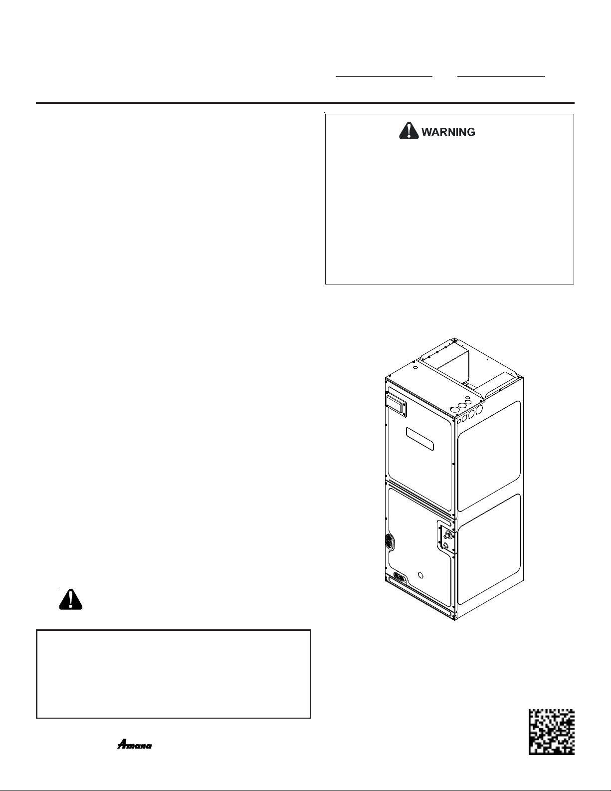
AIR HANDLERS
INSTALLATION & OPERATING INSTRUCTIONS
Contents
© 2018 Goodman Manufacturing Company, L.P.
5151 San Felipe, Suite 500, Houston, TX 77056
www.goodmanmfg.com - or - www.amana-hac.com
P/N: IOA-4030 Date: May 2018
1 Important Safety Instructions ................................... 2
2 Shipping Inspection ................................................... 3
3 Codes & Regulations ................................................. 3
4 Replacement Parts ..................................................... 3
5 Pre-Installation Considerations................................. 3
6 Installation Location................................................... 3
7 Refrigerant Lines........................................................ 5
8 Condensate Drain Lines ............................................ 8
9 Ductwork .................................................................... 9
10 Return Air Filters ........................................................ 9
11 Achieving 1.4% and 2.0% Airflow Low
Leakage Rate .............................................................. 9
12 Electric Heat ............................................................... 9
13 Electrical and Control Wiring .................................. 10
14 AVPTC Motor Orientation .........................................11
15 Cool Cloud HVAC Phone Application ........................11
16 Quick Start Guide for Communicating
Outdoor Units........................................................... 12
17 Quick Start Guide for Non-Communicating
Outdoor Units........................................................... 12
18 Dehumidification ....................................................... 14
19 Auxiliary Alarm Switch ............................................. 14
20 Start-Up Procedure.................................................. 14
21 Accessories .............................................................. 14
22 Ramping Profiles ...................................................... 15
23 Electric Air Cleaner Warning ................................... 15
24 Start-Up Procedure.................................................. 16
25 Regular Maintenance ............................................... 16
26 Air Handler Troubleshooting Matrix ........................ 17
27 Air Handler Display .................................................. 19
28 Airflow Label ............................................................. 22
29 Wiring Diagram ........................................................ 23
O
NLY PERSONNEL THAT HAVE BEEN TRAINED TO INSTALL, ADJUST, SERVICE OR
REPAIR (HEREINAFTER
SHOULD SERVICE THE EQUIP MENT
FOR ANY INJURY OR PROPERTY DAMAGE ARISING FROM IMPROPER SERVICE OR
SERVICE PROCED URES
FOR ANY INJURY OR PROPERTY DAMAGE WHICH MAY RESULT
JURISDICTIONS THAT REQUIRE ONE OR MORE LICENSES TO SERVICE THE EQUIPMENT
SPECIFIED IN THIS MANUAL, ONLY LICENSED PERSONNEL SHOULD SERVICE THE
EQUIPMENT
THE EQUIP MENT SPECIFIED IN THIS MANUAL, OR ATT EM PT ING TO INSTALL, ADJUST
SERVICE OR REPAIR THE EQUIP MENT SPECIFIED IN THIS MANUAL WITHOUT PROPER
TRAINING MAY RESULT IN PRODUCT DAMAGE, PROPERTY DAMAGE, PERSONAL
INJURY OR DEATH
, “
SERVICE
”)
THE EQUIPM ENT SPECIFIED IN THIS MANUAL
. THE
MANUFACTURER WILL NOT BE RESPONSIBLE
. IF
YOU SERVICE THIS UNIT, YOU ASSUME RESPONSIBILITY
. IN
ADDITION, IN
. I
MPROPER INSTALLATION, ADJUSTME NT, SERVICING OR REPAIR OF
.
,
RECOGNIZE THIS SYMBOL AS A
SAFETY PRECAUTION.
ATTENTION INSTALLING PERSONNEL
Prior to installation, thoroughly familiarize yourself with this Installation Manual. Observe all safety warnings. During installation or repair,
caution is to be observed. It is your responsibility to install the product
safely and to educate the customer on its safe use.
is a registered trademark of Maytag Corporation or its related companies and is used under license. All rights reserved.
-
Page 2
1 Important Safety Instructions
The following symbols and labels are used throughout this manual
to indicate immediate or potential safety hazards. It is the
owner’s and installer’s responsibility to read and comply with all
safety information and instructions accompanying these symbols.
Failure to heed safety information increases the risk of personal
injury, property damage, and/or product damage.
To prevent the risk of property damage, personal
injury, or death, do not store combustible materials or
use gasoline or other flammable liquids or vapors in
the vicinity of this unit.
This product is factory-shipped for use with
208/240/1/60 electrical power supply.
reconfigure this air handler to operate with any other
power supply.
To avoid property damage, personal injury or death
due to electrical shock, this unit MUST have an
uninterrupted, unbroken
electrical ground. The
electrical ground circuit may consist of an
appropriately sized electrical wire connecting the
ground lug in the unit control box to the building
electrical service panel.
Other methods of grounding are permitted if performed
in accordance with the National Electric Code
(NEC)/American National Standards Institute
(ANSI)/National Fire Protection Association (NFPA) 70
and local/state codes. In Canada, electrical grounding
is to be in accordance with the Canadian Electric Code
(CSA) C22.1.
When installing or servicing this equipment, safety
clothing, including hand and eye protection, is
strongly recommended. If installing in an area that has
special safety requirements (hard hats, etc.), bserve
these requirements.
DO NOT
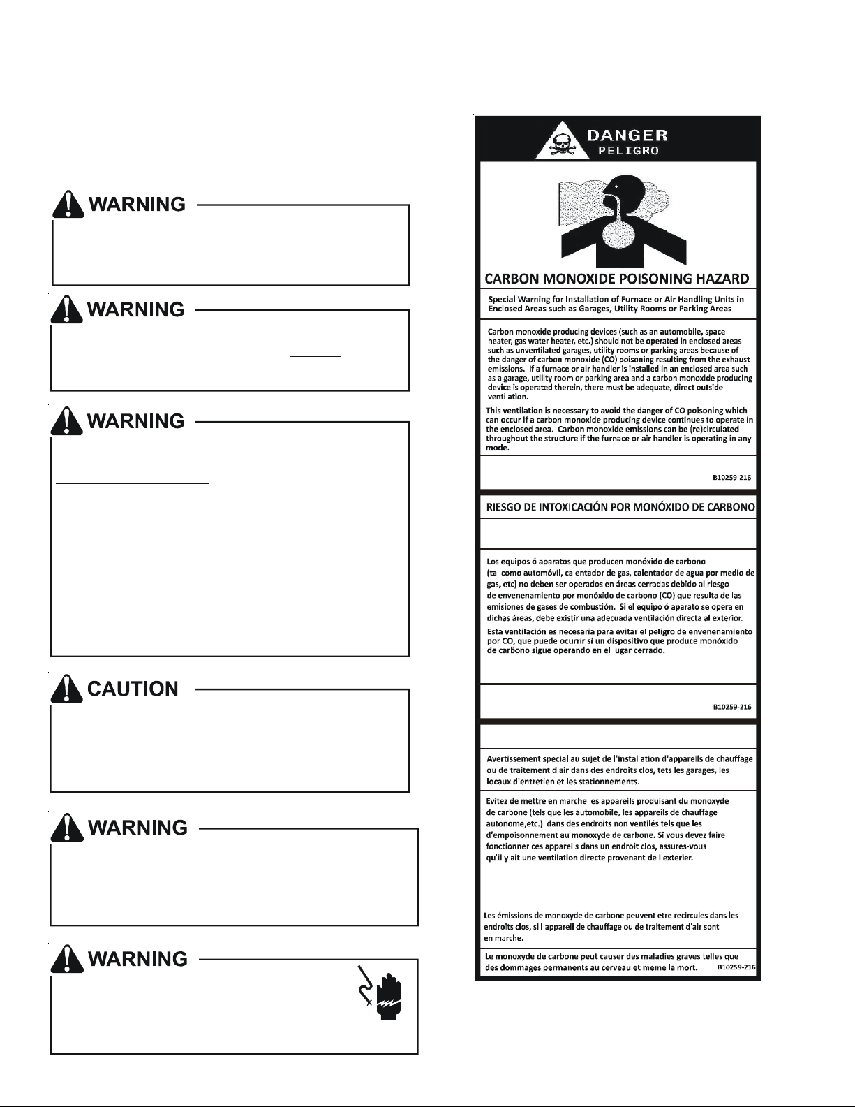
o
CO can cause serious illness includ ing permanent brain
dama ge or d eath.
Advertencia especial para la instalación de calentadores ó manejadoras
de aire en áreas cerradas c omo estacionamientos ó c uartos de servi cio.
Las emisiones de monóxido de carbono pueden circular a través
del aparato cuando se opera en cualquier modo.
El monóxido de carbono puede causar enfermedad es severas
como daño cerebral perma nente ó muerte.
RISQUE D'EMPOISONNEMENT AU
MONOXYDE DE CARBONE
Do not connect to or use any device that is not designcertified by the manufacturer for use with this unit.
Serious property damage, personal injury, reduced
unit performance and/or hazardous conditions may
result from the use of such non-approved devices.
HIGH VOLTAGE!
Disconnect ALL power before servicing.
Multiple power sources may be present.
Failure to do so may cause property damage,
personal injury or death.
Cette ventilation est nécessaire pour éviter le danger d'intoxication
au CO pouvant survenir si un appareil produisant du monoxyde
de carbone con tinue de fonctionne r au sein de la zone confinée.
2
Page 3

2 Shipping Inspection
Always transport the unit upright; laying the unit on its side or top
during transit may cause equipment damage. The installer should
inspect the product upon receipt for shipping damage and subsequent investigation is the responsibility of the carrier. The installer
must verify the model number, specifications, electrical characteristics, and accessories are correct prior to installation. The distributor or manufacturer will not accept claims from dealers for
transportation damage or installation of incorrectly shipped units.
2.1 Parts
Also inspect the unit to verify all required components are
present and intact. Report any missing components immediately to Goodman or to the distributor. Use only factory
authorized replacement parts (see Section 5). Make sure to
include the full product model number and serial number
when reporting and/or obtaining service parts.
2.2 Handling
Use caution when transporting/carrying the unit. Do not move
unit using shipping straps. Do not carry unit with hooks or sharp
objects. The preferred method of carrying the unit after arrival at the job site is to carry via a two-wheel hand truck from
the back or sides or via hand by carrying at the cabinet corners.
3 Codes & Regulations
This product is designed and manufactured to comply with applicable national codes. Installation in accordance with such codes
and/or prevailing local codes/regulations is the responsibility of
the installer. The manufacturer assumes no responsibility for equipment installed in violation of any codes or regulations.
The United States Environmental Protection Agency (EPA) has
issued various regulations regarding the introduction and disposal
of refrigerants. Failure to follow these regulations may harm the
environment and can lead to the imposition of substantial fines.
Should you have any questions please contact the local office of
the EPA and/or refer to EPA’s website www.epa.gov.
4 Replacement Parts
When reporting shortages or damages, or ordering repair parts,
give the complete product model and serial numbers as stamped
on the product. Replacement parts for this product are available
through your contractor or local distributor. For the location of
your nearest distributor consult the white business pages, the yellow page section of the local telephone book or contact:
HOMEOWNER SUPPORT
GOODMAN MANUFACTURING COMPANY, L.P.
19001 KERMIER ROAD,
WALLER, TX 77484
(877) 254-4729
5 Pre-Installation Considerations
5.1 Preparation
Keep this document with the unit. Carefully read all instructions for the installation prior to installing product. Make
sure each step or procedure is understood and any special
considerations are taken into account before starting installation. Assemble all tools, hardware and supplies needed to
complete the installation. Some items may need to be purchased locally. Make sure everything needed to install the
product is on hand before starting.
5.2 System Matches
The entire system (combination of indoor and outdoor sections) must be manufacturer approved and Air-Conditioning, Heating, and Refrigeration Institute (AHRI) listed. NOTE:
Installation of unmatched systems is not permitted. Damage
or repairs due to installation of unmatched systems is not
covered under the warranty.
5.3 Interconnecting Tubing
Give special consideration to minimize the length of refrigerant tubing when installing air handlers. Refer to Remote Cooling/Heat Pump Service Manual RS6200006, and TP-107 Long
Line Set Application R-410A for tubing guidelines. If possible,
allow adequate length of tubing such that the coil may be
removed (for inspection or cleaning services) from the cabinet without disconnecting the tubing.
5.4 Clearances
The unit clearance from a combustible surface may be 0".
However, service clearance must take precedence. A minimum of 24" in front of the unit for service clearance is required. Additional clearance on one side or top will be required for electrical wiring connections. Consult all appropriate regulatory codes prior to determining final clearances.
When installing this unit in an area that may become wet
(such as crawl spaces), elevate the unit with a sturdy, nonporous material. In installations that may lead to physical
damage (i.e. a garage) it is advised to install a protective
barrier to prevent such damage. Always install units such
that a positive slope in condensate line (1/4" per foot) is
allowed.
5.5 Horizontal Applications
If installed above a finished living space, a secondary drain
pan (as required by many building codes), must be installed
under the entire unit and its condensate drain line must be
routed to a location such that the user will see the condensate discharge.
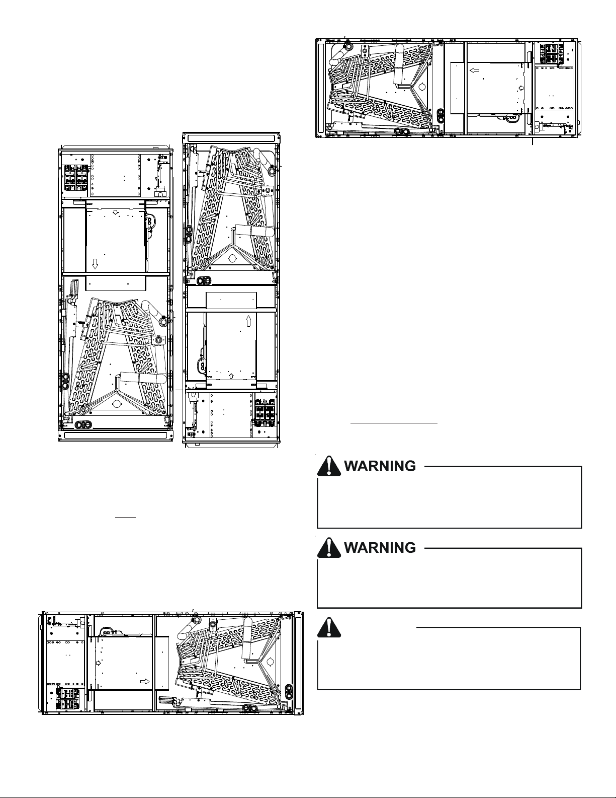
6 Installation Location
NOTE: These air handlers are designed for indoor installation
only.
The AVPTC**14** product line may be installed in one of the
upflow, downflow, horizontal left or horizontal right orientations
as shown in Figures 2, 3, 4 and 5. The unit may be installed in
upflow or horizontal left orientation as shipped (refer to specific
sections for more information).
3
Page 4
Minor field modifications are necessary to convert to downflow
or horizontal right as indicated in below sections.
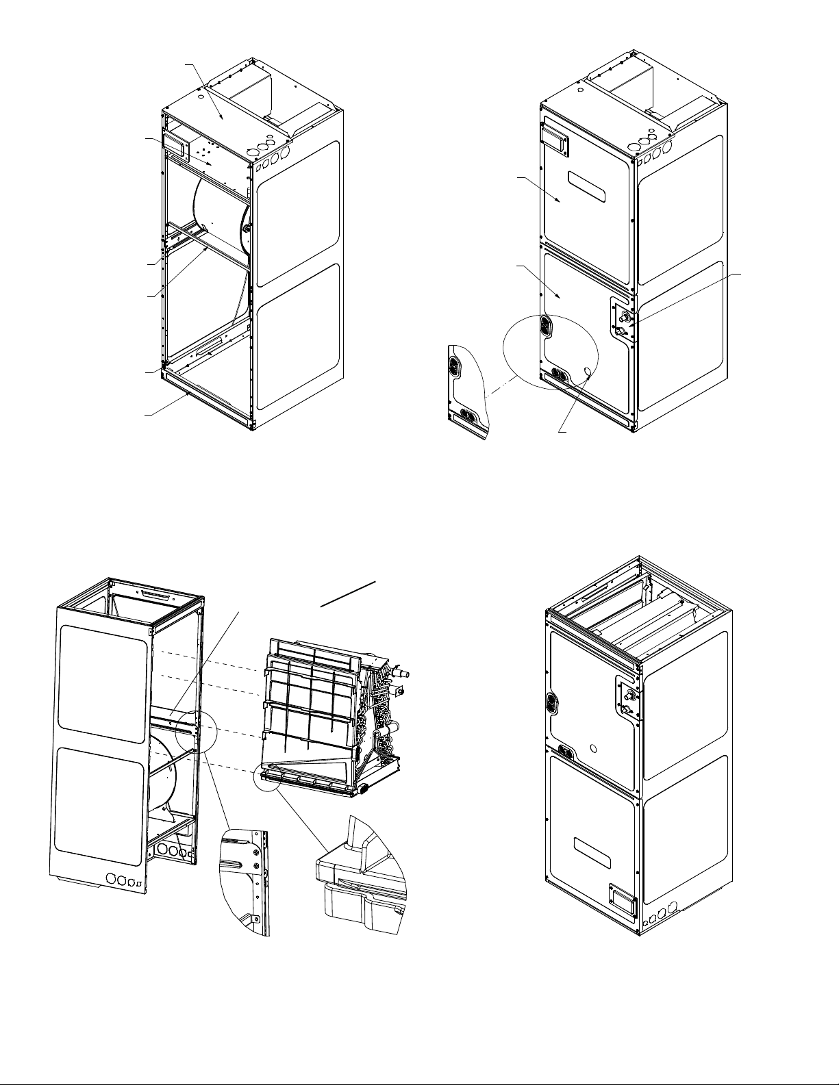
6.1 Upflow Installation
No field modifications are mandatory; however, to obtain
maximum efficiency, the horizontal drip shield, side drain pan
and drain pan extension can be removed.
Side Drain Pan and Extension Removal: Refer to Figure 1, remove the two (2) screws that secure the drip shield support
brackets to the condensate collectors (front and back). Unsnap the side drain pan from the main drain pan using a screw
driver or any small lever. The side drain pan, drip shield brackets and the drain pan extension may now be removed. From
Figure 1, drain port labeled (A) is the primary drain for this
application and condensate drain line must be attached to
this drain port. Drain port (a) is for the secondary drain line (if
used).
Drip Pan
Extension
Side
Drain
Pan
Screw
b
B
Drip Shield Bracket
Drip Shield
CMK0008
Condensate
Kit
AVPTC25B14 AVPTC29B14 AVPTC31C14 AVPTC49D14 AVPTC33C14 AVPTC49C14
CMK0009
Condensate
Kit
AVPTC37B14 AVPTC37C14 AVPTC61D14 AVPTC39C14
CMK0010
Condensate
Kit
AVPTC 37D 14
AVPTC59C14
AVPTC 59D 14
CMK0012
Condensate
Kit
CMK0013
Condensa te
Kit
CMK0014
Condensate
Kit
CONDENSATE KIT
TABLE 1
6.3 Downflow/Horizontal Right Installation
IMPORTANT NOTE: In the downflow application, to prevent
coil pan “sweating”, a downflow kit (DFK) is available through
your local Goodman distributor. The DFK is not supplied with
the air handler and is required by Goodman on all downflow
installations. See Table 2 for the correct DFK and follow the
instructions provided for installation.
MODEL LIST FOR DOWNFLOW KITS
DFK-B
Downflow Kit
DFK-C
Downflow Kit
DFK-D
Downflow Kit
AVPTC25B14** AVPTC31C14** AVPTC37D14**
AVPTC29B14** AVPTC37C14** AVPTC49D14**
AVPTC35B14** AVPTC59C14** AVPTC59D14**
AVPTC37B14** AVPTC33C14** AVPTC61D14**
AVPTC39C14**
AVPTC49C14**
DOWNFLOW KIT
TABLE 2
Pna
A
Main Drain Pan
SIDE DRAIN PAN REMOVAL
Figure 1
6.2 Horizontal Left Installation
No field modifications are permissible for this application.
The bottom right drain connection is the primary drain for
this application and condensate drain line must be attached
to this drain connection. The top connection of the three drain
connections on the drain pan must remain plugged for this
application. The bottom left drain connection is for the secondary drain line (if used).
In applications where the air handler is installed in the horizontal left position, and the return air environment see humidity levels above 65% relative humidity coupled with total
external static levels above 0.5” e.s.p., a condensate kit is
available for field application. Kit nomenclature can be found
in Table 1.
Refer to Figure 6 and 7 for the location of the components referenced in the following steps.
1. Before inverting the air handler, remove blower access
panel and coil access panel. The coil access panel and
tubing panel may remain screwed together during this
procedure. Remove and retain the seven (7) screws
securing the coil access panel to the cabinet and the six
(6) screws securing the blower access panel to the
cabinet.
2. Slide the coil assembly out using the drain pan to pull the
assembly from the cabinet.
NOTE: DO NOT USE MANIFOLDS OR FLOWRATOR TO
PULL THE COIL ASSEMBLY OUT. FAILURE TO DO SO MAY
RESULT IN BRAZE JOINT DAMAGE AND LEAKS.
3. Removal of the center support is required on units with
21" wide cabinet. Remove and retain the two (2) screws
that secure the center support to the cabinet. Remove
the center support.
4. Using the drain pan to hold the coil assembly, slide the
coil assembly back into the cabinet on the downflow
brackets as shown in Figure 8.
5. Re-install the center support (if removed) using the two
(2) screws removed in Step 4.
6. Re-install the access panels removed in Step 1 as shown
4
Page 5
in Figure 9.
7. The bottom left drain connection is the primary drain for
this application and condensate drain line must be
attached to this drain connection. The top connection of
the three drain connections on the drain pan must remain
plugged for this application. The bottom left drain
connection is for the secondary drain line (if used).
HORIZONTAL RIGHT
Figure 5
7 Refrigerant Lines
NOTE: Refrigerant tubing must be routed to allow adequate ac-
cess for servicing and maintenance of the unit.
7.1 Tubing Size
For the correct tubing size, follow the specification for the
condenser/heat pump.
7.2 Tubing Preparation
All cut ends are to be round, burr free, and clean. Failure to
follow this practice increases the chances for refrigerant leaks.
The suction line is spun closed and requires tubing cutters to
remove the closed end.
UPFLOW DOWFLOW
Figure 2 Figure 3
NOTE: If removing only the coil access panel from the unit, the
filter access panel must be removed first. Failure to do so may
result in panel damage.
Do not install the air handler in a location that violates the
instructions provided with the condenser. If the unit is located in
an unconditioned area with high ambient temperature and/or high
humidity, the air handler may be subject to nuisance sweating of
the casing. On these installations, a wrap of 2" fiberglass insulation
with a vapor barrier is recommended.
NOTE: To prevent possible damage to the tubing joints, do
not handle coil assembly with manifold or flowrator tubes.
Always use clean gloves when handling coil assemblies.
NOTE: The use of a heat shield is strongly recommended when
brazing to avoid burning the serial plate or the finish of the
unit. Heat trap or wet rags must be used to protect heat sensitive components such as service valves and TXV valves sensing bulb.
This product is factory-shipped with R410A and dry
nitrogen mixture gas under pressure. Use appropriate
service tools and follow these instructions to prevent
injury.
A quenching cloth is strongly recommended to prevent
scorching or marring of the equipment finish when
brazing close to the painted surfaces. Use brazing
alloy of 5% minimum silver content.
CAUTION
Applying too much heat to any tube can melt the tube. Torch
heat required to braze tubes of various sizes must be
proportional to the size of the tube. Service personnel must
use the appropriate heat level for the size of the tube being
brazed.
HORIZONTAL LEFT
Figure 4
5
Page 6
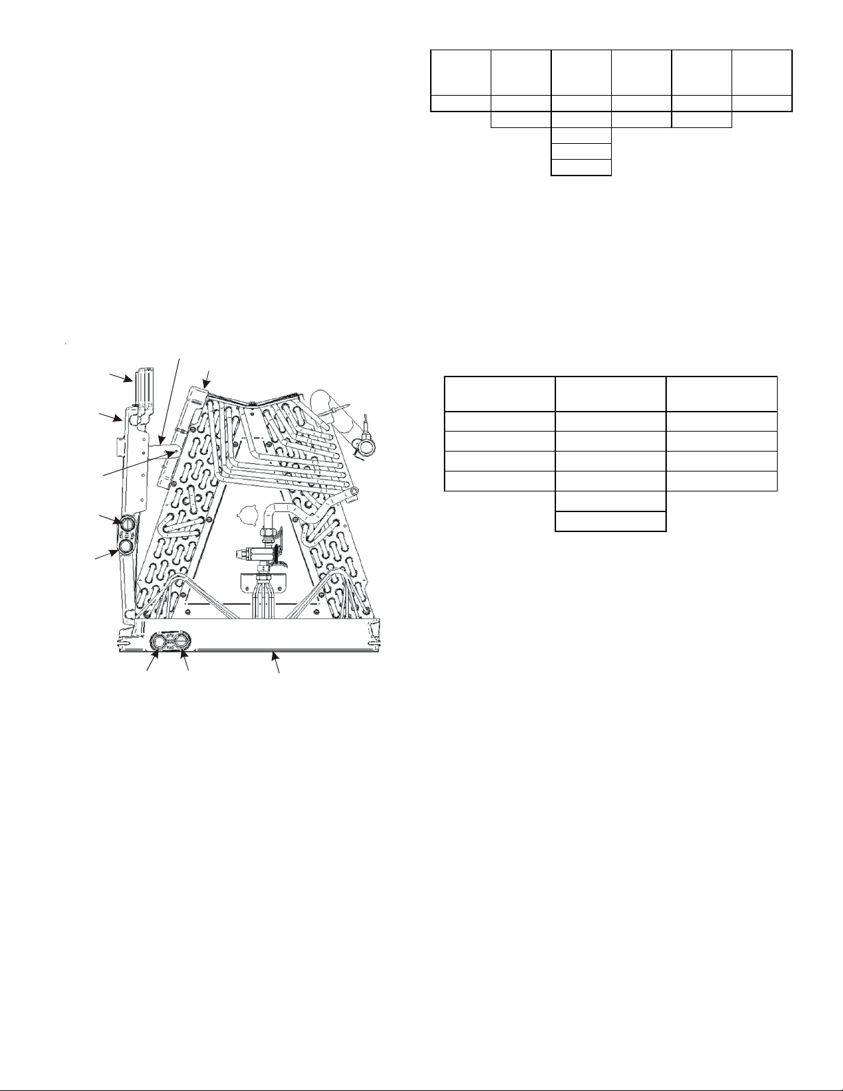
Upper Tie Plate
Control
Deck
Blower
Access
Panel
Downflow
Bracket
Center
Support
Filter
Bracket
Filter
Access
Panel
INTERNAL PART TERMINOLOGY
Figure 6
Coil Slides
on the downflow bracket
Access
Remove side drain pan
extension for
downflow application
Coil
Panel
Tubing
Panel
UV
Knockout
EXTERNAL PART TERMINOLOGY
Figure 7
IMPORTANT NOTE:
Ensure coil slides on the rails along the groove provided on the drain pan side walls.
Failure to do so will result in improper condensate drainage.
COIL INSTALLATION FOR DOWNFLOW
Figure 8
6
ACCESS PANEL CONFIGURAATION
FOR DOWNFLOW
OR HORIZONTAL RGHT
Figure 9
Page 7
7.3 Tubing Connections for TXV Models
TXV models come with factory installed TXV with the bulb
pre-installed on the vapor tube.
1. Remove refrigerant tubing panel or coil (lower) access
panel.
2. Remove access valve fitting cap and depress the valve
stem in access fitting to release pressure. No pressure
indicates possible leak.
3. Replace the refrigerant tubing panel.
4. Remove the spin closure on both the liquid and suction
tubes using a tubing cutter.
5. Insert liquid line set into liquid tube expansion and slide
grommet about 18" away from braze joint.
6. Insert suction line set into suction tube expansion and
slide insulation and grommet about 18" away from braze
joint.
7. Braze joints. Quench all brazed joints with water or a wet
rag upon completion of brazing.
NOTE: The sensing bulb must be permanently located. A heat
shield, heat trap, or wet rag must be used during brazing to prevent damage to the TXV valve.
8. Replace access panels, suction line grommet, insulation
and all screws.
SUCTION LINE
WITH SPIN CLOSURE
RUBBER
GROMMET
Suction Line Grommet
Figure 11
7.4 Thermal Expansion Valve System Adjustment
Run the system at Cooling for 10 minutes until refrigerant
pressures stabilize. Use the following guidelines and methods to check unit operation and ensure that the refrigerant
charge is within limits. Charge the unit on low stage.
1. Purge gauge lines. Connect service gauge manifold to
base-valve service ports.
2. Temporarily install a thermometer on the liquid line at
the liquid line service valve and 4-6’’ from the compressor
on the suction line. Ensure the thermometer makes
adequate contact and is insulated for best possible
readings. Use liquid line temperatice to determine
subcooling and vapor temperature to determine superheat.
3. Check subcooling and superheat. Systems with TXV
application should have a subcooling of 7 to 9°F and
superheat of 7 to 9°F
a. If subcooling and superheat are low, adjust TXV to 7 to
9°F, and then check subcooling.
NOTE: To adjust superheat, turn the valve stem clockwise to increase and counter clockwise to decrease.
b. If subcooling is low and superheat is high, add charge to
raise subcooling to 7 to 9°F, and then check superheat.
c. If subcooling and superheat are high, adjust TXV valve to
7 to 9° superheat, then check subcooling.
d. If subcooling is high and superheat is low, adjust TXV valve
to 7 to 9° superheat and remove charge to lower the subcooling
to 7 to 9°F.
NOTE: Do NOT adjust the charge based on suction pressure unless there is a gross undercharge.
4. Disconnect manifold set, and installation is complete
NOTE: Check the Schrader ports for leaks and tighten valve cores
if necessary. Install caps finger-tight.
SUBCOOL FORMULA=
SAT. LIQUID LINE TEMP - LIQUID LINE TEMP
SUPERHEAT FORMULA=
SUCT. LINE TEMP - SAT. SUCT. TEMP
SATURATED SUCTION PRESSURE
TEMPERATURE CHART
SUCTION PRESSURE
PSIG R-22 R-410A
50 26 1
52 28 3
54 29 4
56 31 6
58 32 7
60 34 8
62 35 10
64 37 11
66 38 13
68 40 14
70 41 15
72 42 16
74 44 17
76 45 19
78 46 20
80 48 21
85 50 24
90 53 26
95 56 29
100 59 31
110 64 36
120 69 41
130 73 45
140 78 49
150 83 53
160 86 56
7
170 90 60
SATURATED SUCTION
TEMPERATURE ºF
Page 8

SATURATED LIQUID PRESSURE
TEMPERATURE CHART
CAUTION
LIQUID PRESSURE
PSIG R-22 R-410A
200 101 70
210 105 73
220 108 76
225 110 78
235 113 80
245 116 83
255 119 85
265 121 88
275 124 90
285 127 92
295 130 95
305 133 97
325 137 101
355 144 108
375 148 112
405 155 118
415 157 119
425 n/a 121
435 n/a 123
445 n/a 125
475 n/a 130
500 n/a 134
525 n/a 138
550 n/a 142
575 n/a 145
600 n/a 149
625 n/a 152
SATURATED LIQUID
TEMPERATURE ºF
8 Condensate Drain Lines
The coil drain pan has a primary and a secondary drain with 3/4"
NPT female connections. The connectors required are 3/4" NPT
male, either PVC or metal pipe, and should be hand tightened to a
torque of no more than 37 in-lbs. to prevent damage to the drain
pan connection. An insertion depth of approximately 3/8” to 1/2”
(3-5 turns) should be expected at this torque.
1. Ensure drain pan hole is not obstructed.
2. To prevent potential sweating and dripping on to finished
space, it may be necessary to insulate the condensate
drain line located inside the building. Use Armaflex® or
similar material.
A secondary condensate drain connection has been provided for
areas where the building codes require it. Pitch all drain lines a
minimum of 1/4" per foot to provide free drainage. Provide required support to the drain line to prevent bowing. If the secondary drain line is required, run the line separately from the primary drain and end it where condensate discharge can be easily
seen.
NOTE: Water coming from secondary line means the coil primary
drain is plugged and needs immediate attention.
If secondary drain is not installed, the secondary
access must be plugged.
Insulate drain lines located inside the building or above a finished living space to prevent sweating. Install a condensate trap
to ensure proper drainage.
NOTE: When units are installed above ceilings, or in other
locations where damage from condensate overflow may
occur, it is MANDATORY to install a field fabricated auxiliary
drain pan under the coil cabinet enclosure.
The installation must include a “P” style trap that is located as
close as is practical to the evaporator coil. See Figure 12 for
details of a typical condensate line “P” trap.
NOTE: Units operating in high static pressure applications may
require a deeper field constructed “P” style trap than is shown in
Figure 12 to allow proper drainage and prevent condensate overflow.
Drain
Connection
Air Handler
POSITIVE LIQUID
SEAL REQUIRED
AT T R AP
2" MIN.
3" MIN.
Figure 12
NOTE: Trapped lines are required by many local codes. In the
absence of any prevailing local codes, please refer to the requirements listed in the Uniform Mechanical Building Code.
A drain trap in a draw-through application prevents air from
being drawn back through the drain line during fan operation
thus preventing condensate from draining, and if connected to a
sewer line to prevent sewer gases from being drawn into the airstream during blower operation.
Use of a condensate removal pump is permitted when necessary.
This condensate pump should have provisions for shutting off the
control voltage should a blocked drain occur. A trap must be
installed between the unit and the condensate pump.
IMPORTANT NOTE: The evaporator coil is fabricated with oils
that may dissolve styrofoam and certain types of plastics.
Therefore, a removal pump or float switch must not contain any of
these materials.
Tip: Priming the “P” trap may avoid improper draining at the initial installation and at the beginning of the cooling season.
8
Page 9
9 Ductwork
This air handler is designed for a complete supply and return
ductwork system.
To ensure correct system performance, the ductwork is to be
sized to accommodate 350-450 CFM per ton of cooling with the
static pressure not to exceed 0.5" in w.c. Refer to ACCA Manual
D, Manual S and Manual RS for information on duct sizing and
application. Flame retardant ductwork is to be used and sealed
to the unit in a manner that will prevent leakage.
NOTE: A downflow application with electric heat must have an Lshaped sheet metal supply duct without any outlets or registers
located directly below the heater.
9.1 Return Ductwork
DO NOT LOCATE THE RETURN DUCTWORK IN AN AREA
THAT CAN INTRODUCE TOXIC, OR OBJECTIONABLE FUMES/
ODORS INTO THE DUCTWORK. The return ductwork is to
be connected to the air handler bottom (upflow configuration).
10 Return Air Filters
Each installation must include a return air filter. This filtering
may be performed at the air handler using the factory filter rails
or externally such as a return air filter grille. When using the
factory filter rails, a nominal 16x20x1”, 20x20x1” or 24x20x1”
(actual dimension must be less than 23-½”x20”) filter can be installed on a B, C and D cabinet respectively (the cabinet size is
the seventh letter of the model number).
11 Achieving 1.4% and 2.0% Airflow Low Leakage Rate
Ensure all the gaskets remain intact on all surfaces as shipped
with the unit. These surfaces are areas between the upper tie
plate and coil access panel, blower access and coil access panels,
and between the coil access and filter access panels. Ensure upon
installation, that the plastic breaker cover is sitting flush on the
blower access panel and all access panels are flush with each
other and the cabinet. With these requirements satisfied, the
unit achieves less than 1.4% airflow leakage @ 0.5 inch wc static
pressure and less than 2% airflow leakage @1inch wc static pressure when tested in accordance with ASHRAE Standard 193.
12 Electric Heat
Do not operate this product without all the ductwork
attached.
CFM
800 121923313756
1000 9 1519253044
1200 8 12152125374962
1400 7 11131821324253
1600 6 9 12 15 19 28 37 46
1800 5 8 10 14 16 25 33 41
2000 5 7 9 1215223037
3 5 6 8 10 15 19/20 25
HEAT KIT NOMINAL kW
230/1/60 SUPPLY VOLTAGE - TEMP. RISE °F
Table 2
CFM
800 111822303554
1000 9 1418242842
1200 7 12152024354759
1400 6 10131720304051
1600 6 9 11 15 18 27 35 44
1800 5 8 10 13 16 24 31 39
2000 4 7 9 12 14 21 28 35
3568101519/2025
HEAT KIT NOMINAL kW
220/1/60 SUPPLY VOLTAGE - TEMP. RISE °F
Table 3
CFM
800 1017212833
1000 8 1317222740
1200 7 11141922334556
1400 6 10121619293848
1600 5 8 10 14 17 25 33 42
1800 5 7 9 12 15 22 30 37
2000 4 7 8 11 13 20 27 33
3568101519/2025
HEAT KIT NOMINAL k W
208/1/60 SUPPLY VOLTAGE - TEMP. RISE °F
Table 4
Model
AVPTC25B14 550 650 700 800 850 875
AVPTC29B14 550 650 700 800 875 875
AVPTC35B14 550 650 700 800 875 1050
AVPTC37B14 550 650 700 800 875 1050
AVPTC31C14 600 700 770 880 97 0 1090 1280
AVPTC33C14 600 700 750 850 92 0 95 0
AVPTC37C14 700 770 880 970 1090 1280
AVPTC39C14 700 770 880 970 1090 1280
AVPTC49C14 800 800 950 1 090 1290 1345
AVPTC59C14 800 800 950 1 090 1290 1345
AVPTC37D14 870 970 1060 1120 1220 1250
AVPTC49D14 950 1060 1150 1220 1520
AVPTC59D14 990 1110 1200 1240 1520 1520
AVPTC61D14 1030 1150 1 250 1320 1 650 1690 1750
35681015192025
HEATE R (kW)
MINIMUM CFM REQUIREMENTS FOR HEATER KITS
Table 5
Refer to the installation manual provided with the electric heat
kit for the correct installation procedure. All electric heat must
be field installed. If installing this option, the ONLY heat kits that
are permitted to be used are the HKS series. Refer to the air handler unit’s Serial and Rating plate or the HKS specification sheets
to determine the heat kits compatible with a given air handler.
No other accessory heat kit besides the HKS series may be installed in these air handlers.
The heating mode temperature rise is dependent upon the system airflow, the supply voltage, and the heat kit size (kW) selected.
Use data provided in Tables 3, 4 and 5 to determine the temperature rise (°F).
NOTE: For installations not indicated above the following formula
is to be used:
TR = (kW x 3412) x (Voltage Correction) / (1.08 x CFM)
Where: TR = Temperature Rise
kW = Heater Kit Actual kW
3412 = Btu per kW
VC* = .96 (230 Supply Volts)
= .92 (220 Supply Volts)
= .87 (208 Supply Volts)
1.08 = Constant
CFM = Measured Airflow
VC* (Voltage Correction)
9
Page 10

NOTE: The Temperature Rise Tables can also be used to estimate
the air handler airflow delivery. When using these tables for this
purpose set the room thermostat to maximum heat and allow
the system to reach steady state conditions. Insert two
thermometers, one in the return air and one in the supply air.
The temperature rise is the supply air temperature minus the
return air temperature. Using the temperature rise calculated,
CFM can be estimated from the TR formula above. See Spec
Sheets and/or Service Manual for more information.
13 Electrical and Control Wiring
IMPORTANT: All routing of electrical wiring must be made
through provided electrical knockouts. Do not cut, puncture or
alter the cabinet for electrical wiring.
13.1 Building Electrical Service Inspection
This unit is designed for single-phase electrical supply only.
DO NOT OPERATE ON A THREE-PHASE POWER SUPPLY. Measure the power supply to the unit. The supply voltage must
be measured and be in agreement with the unit nameplate
power requirements and within the range shown.
• Wire used must carry the Minimum Circuit Ampacity
(MCA) listed on the unit’s Series and Rating Plate.
• Refer to the NEC (USA) or CSA (Canada) for wire sizing.
The unit MCA for the air handler and the optional electric
heat kit can be found on the unit Series and Rating Plate.
• Wire must be sized to allow no more than a 2% voltage
drop from the building breaker/fuse panel to the unit.
• Wires with different insulation temperature rating have
varying ampacities - be sure to check the temperature rating used.
Refer to the latest edition of the National Electric Code or
in Canada the Canadian Electric Code when determining
the correct wire size.
13.3 Maximum Overcurrent Protection (MOP)
Every installation must include an NEC (USA) or CEC
(Canada) approved overcurrent protection device. Also,
check with local or state codes for any special regional requirements.
Nominal Input Minimum Voltage Maximum Voltage
208-240 197 253
ELECTRICAL VOLTAGE
Table 6
13.2 Wire Sizing
Wire size is important to the operation of your equipment.
Use the following check list when selecting the appropriate
wire size for your unit.
FIRE HAZARD!
To avoid the risk of property damage, personal injury
or fire, use only copper conductors.
HIGH VOLTAGE!
Disconnect ALL power before servicing.
Multiple power sources may be present.
Failure to do so may cause property damage,
personal injury or death.
Protection can be in the form of fusing or HACR style circuit
breakers. The Series and Rating Plate provides the maximum overcurrent device permissible.
NOTE: Fuses or circuit breakers are to be sized larger than
the equipment MCA but not to exceed the MOP.
13.4 Electrical Connections – Supply Voltage
IMPORTANT NOTE: USE COPPER CONDUCTORS ONLY.
Knockouts are provided on the air handler top panel and
sides of the cabinet to allow for the entry of the supply
voltage conductors, as shown in Figure 13. If the knockouts
on the cabinet sides are used for electrical conduit, an
adapter ring must be used in order to meet UL1995 safety
requirements. An NEC or CEC approved strain relief is to
be used at this entry point. Some codes/municipalities require the supply wire to be enclosed in conduit. Consult
your local codes.
Top of
Cabinet
HIGH VOLTAGE!
To avoid property damage, personal injury or death
due to electrical shock, this unit MUST have an
uninterrupted, unbroken
electrical ground circuit may consist of an
appropriately sized electrical wire connecting the
ground lug in the unit control box to the building
electrical service panel.
Other methods of grounding are permitted if performed
in accordance with the National Electric Code
(NEC)/American National Standards Institute
(ANSI)/National Fire Protection Association (NFPA) 70
and local/state codes. In Canada, electrical grounding
is to be in accordance with the Canadian Electric Code
(CSA) C22.1.
electrical ground. The
Side of
Cabinet
KNOCK-OUT FOR ELECTRICAL CONNECTIONS
Figure 13
10
Page 11

13.4.1 Air Handler Only (Non-Heat Kit Models)
A
A
The building supply connects to the stripped black and red
wires contained in the air handler electrical compartment
cavity. A ground screw is also contained in this area. Attach
the Supply wires to the air handler conductors as shown in
the unit wiring diagram using appropriately sized solderless
connectors or other NEC or CEC approved means.
13.4.2 Air Handler - Non-Circuit Breaker Heat Kits
A terminal block is provided with the HKS kit to attach the
power supply and air handler connections. Follow the HKS
Installation Manual and wiring diagram for complete wiring details.
13.4.3 Air Handler With Circuit Breaker Heat Kit
The air handler has a plastic cover on the upper access
panel that will require either one or both sections to be
removed to allow the heat kit circuit breaker(s) to be installed. The circuit breakers have lugs for power supply
connection. See the HKS Installation Instructions for further details.
14 AVPTC Motor Orientation
If the unit is in the upflow position, there is no need to rotate the
motor. If the unit is in the downflow position, loosen motor
mount and rotate motor as shown in the AVPTC Motor
Orientation figure below. Be sure motor is oriented with the
female connections on the casing down. If the motor is not
oriented with the connections down, water could collect in the
motor and may cause premature failure.
15 Cool Cloud HVAC Phone Application
Actual screens may look different based on the mobile device
being used.
FRONT VIEW
FEMALE CONNECTIONS
AVPTC Motor Orientation
Figure 14
SIDE VIEW
W
RNING
SOFTW
RE VER.
TOP
Figure 15
This air handler is Bluetooth ready and functions with the Cool
Cloud HVAC phone application designed to improve the
contractor’s setup / diagnostic experience. Users can see specific
model information, review active diagnostic error codes, observe
system menu testing of all operational modes (heat / cool / fan)
directly from the phone. The phone application is also capable of
directly updating the air handler software anytime updates are
available. The application will automatically notify the user.
NOTE: The software update may take up to 20 minutes to
complete.
11
Page 12

16 Quick Start Guide for Communicating Outdoor Units
EXTREMELY IMPORTANT: For all cooling calls the system only
requires a single Y input from the thermostat. For all heating
calls (including applications with backup electric heater kits) the
system only requires a single W input from the thermostat.
Internal algorithms will control all available cooling and heating
stages based on these inputs. Any single-stage 24VAC thermostat
can be used. For proper operation, the thermostat must be setup
to control a single stage AC outdoor unit and to control single
stage electric heat operation. The control board does not
accommodate an O wire thermostat input (reversing valve signal).
If a heat pump is installed, the thermostat should be setup as
stated above. Setting the thermostat for the heat pump control
or multistage control may result in incorrect performance.
1. Connect all necessary thermostat wires to the thermostat
connector on the air handler control as instructed by the
applicable wiring diagrams shown in this section.
2. Connect the 1 & 2 wires between the indoor and outdoor
unit for communicating operation.
Note: Verify two stage outdoor units include a 24VAC
transformer (for outdoor control board power). Two
stage outdoor units may not behave properly without
this 24 VAC transformer.
16.2 Electric Heater Kit Testing
1. Select the electric heat icon after entering the air handler
menus in the Cool Cloud HVAC phone application.
2. Select any value less than 50% for low stage operation
and any value greater than 50% for high stage operation.
3. Confirm thermostat heating and cooling calls function
properly with equipment.
17 Quick Start Guide for Non-Communicating Outdoor
Units
EXTREMELY IMPORTANT: For two stage electric heat kit control
the system only needs a single W input. Internal algorithms will
control staging automatically based on the single W input. For
non-communicating outdoor unit wiring, see instructions below:
1. Use the wiring diagrams on the next page to connect low
voltage thermostat wires.
NOTE: When installing the air handler with a noncommunicating heat pump, wire directly to the “O”
terminal on the non-communicating heat pump. See the
following figures.
Figure 16
3. Download the Cool Cloud HVAC phone application for
charging and to configure /test system.
NOTE: When new versions of Bluetooth Communication Software and Air Handler Control Software are available, the phone
application notifies the user. Software updates are classified as
either optional or mandatory and installed by using the phone
application. Ensure all mandatory software updates and install if
necessary.
16.1 Charging
1. Two-stage outdoor units using the Cool Cloud HVAC
application:
a. Using the cooling icon after entering the outdoor
unit menus, energize the outdoor unit at 100%
capacity.
b. Charge the outdoor unit as required using the
charging information provided with the outdoor
equipment.
Figure 17
FIgure 18
12
Page 13

Figure 19
4. Go to the Tonnage Units Menu () and select the
tonnage value that corresponds to the desired airflow for
the outdoor unit. See the following table.
NOTE: For the two stage non-communicating outdoor
units, system will stage airflow automatically for low
stage operation.
NOTE: The system will not provide airflows above the max Airflow
Value.
Figure 20
2. Download the Cool Cloud HVAC phone application.
Note: When new versions of Bluetooth Communication
Software and Air Handler Control Software are available,
the phone application notifies the user. Software updates
are classified as either optional or mandatory and
installed by using the phone application. Ensure all
mandatory software updates have been installed. Review
notes for optional software updates and install if
necessary.
3. Go to the Non-Comm Outdoor Setting Menu () using
the on board push buttons or the Cool Cloud HVAC
phone application. Selec t “” for single stage Air
Conditioners, “” for single stage Heat Pumps, “”
for two stage Air Conditioners and “” for 2 stage Heat
Pumps.
Model MAX CFM
AVPTC25B14
AVPTC29B14
AVPTC35B14
AVPTC37B14
AVPTC33C14 1300
AVPTC31C14
AVPTC37C14
AVPTC39C14
AVPTC37D14
AVPTC49C14
AVPTC49D14
AVPTC59C14
AVPTC59D14
AVPTC61D14
1200
1600
1800
1900
2100
5. Use the Cool Cloud HVAC phone application to configure/
test air handler operations.
NOTE: The phone application cannot test a non- communicating
outdoor unit. The thermostat will be required for outdoor unit
testing.
17.1 Electric Heater Kit Testing
1. Two-stage outdoor units:
a. Provide a second stage cooling call from the
thermostat and charge accordingly.
2. Single-stage outdoor units:
a. Provide a cooling call from the thermostat and
charge accordingly.
13
Page 14

17.2 Electric Heater Kit Testing
1. Select the electric heat icon after entering the air handler
menus while using the Cool Cloud phone application.
2. Select any value less than 50% for low stage operation
and any value greater than 50% for high stage operation.
3. Confirm thermostat heating and cooling calls function
properly for high stage operation.
18 Dehumidification
Dehumidification allows the air handler’s circulator blower to
operate at a reduced speed during a combined thermostat call
for cooling and a dehumidification call from the thermostat or
humidistat. This lower blower speed increases dehumidification
of the conditioned air as it passes through the indoor coil. The
control board is equipped with a 24 volt dehumidification input
(DH) located on the thermostat wiring connector. The terminal
can be configured to enable dehumidification when the input is
energized or de-energized. When using an external dehumidistat,
connect it between the R and DH terminals. If the humidistat
closes on humidity rise or the thermostat energizes this terminal
when dehumidifcation is required, set the control board Dehum
Logic Menu () to “” using the push buttons or Cool Cloud
HVAC phone application. If the humidistat opens on humidity or
the thermostat de-energizes this terminal when dehumidification
is required, set the Dehum Logic Menu to “” using the push
buttons or Cool Cloud HVAC phone application.
19 Auxiliary Alarm Switch
The control is equipped with a 24VAC Aux Alarm to be
used for a condensate switch install (designated by CON-DENSATE
IN/OUT on the control). By default, the connected
AUX switch is normally closed and opens when the
water level in the evaporator coil base pan reaches an
undesirable level. The control responds by displaying a “”
error code and turning off the outdoor condensing
unit. If the AUX switch is detected to be in the closed
position for 30 seconds, normal operation resumes and
the error message is no longer displayed.
enter into a main menu and to then permanently select
options within those menus.
NOTE: After scrolling to the desired option within a menu,
that option may be flashing on the 7-segment displays.
This indicates the option has not been officially selected.
Pressing the Center button two times will select that
option. The first press will stop the flashing. The second
will make the selection official and return you to the main
menu.
21 Accessory Control (Humidifiers, Dehumidifiers,
Ventilators)
If an external humidifier, dehumidifier or ventilator is installed,
it may require airflow from the HVAC system to
function properly.
1. Make sure the installed 24VAC thermostat is capable of
controlling the accessory or accessories.
2. Connect the appropriate accessory control wires to the
accessory devices from the thermostat (see thermostat
manual for connection and setup instructions).
3. If the thermostat is capable of providing a continuous fan
call (G signal) during accessory operation:
Make sure to connect the thermostat G terminal to the G
terminal on the indoor unit. Setup thermostat to ensure
G signal is energized during accessory operation.
20 Start-Up Procedure
Figure 21
The air handler includes three on-board push buttons allowing
users to navigate indoor and outdoor system menus.
The Right and Left buttons allow the user to scroll through
the main menus and to then scroll through available options
within specific menus. The Center button is used to
FIgure 22
4. Select the appropriate fan only airflow for the accessory
using the indoor unit push button menus or the Cool
Cloud HVAC phone application.
5. Using the thermostat, independently test each accessory
in addition to the independently testing continuous fan
mode.
14
Page 15

22 Ramping Profiles
The variable-speed circulator offers four different ramping
profiles. These profiles may be used to enhance cooling
performance and increase comfort level. Select the desired
ramping profile using the Cool Cloud phone application or the
push button menus.
23 Electric Air Cleaner Warning
The control is equipped with an Accessory Relay and a pair of ¼
inch accessory terminals which is normally open, labeled EAC-IN
and EAC-OUT (see accessory contacts graphic). The Accessory
Relay is configured to close anytime the blower is running. A
closed relay means the two terminals will have continuity between them (the control does not energize these contacts). It is
recommended to utilize 24VAC with these terminals and limit
the current to 1A.
Figure 23
FIgure 24
15
Page 16

24 Start-Up Procedure
• Prior to start-up, ensure that all electrical connections are
properly sized and tightened.
• All panels must be in place and secured. For Air Tight
application, neoprene gasket must be positioned at
prescribed locations to achieve low airflow as stated in
section 13.
• Tubing must be leak free.
• Unit should be elevated, trapped and pitched to allow for
drainage.
• Low voltage wiring is connected.
• Auxiliary drain is installed when necessary and pitched to
allow for drainage.
• Drain pan and drain tubing has been leak checked.
• Return and supply ducts are sealed.
• Unit is elevated when installed in a garage or where
flammable vapors may be present.
• Unit is protected from vehicular or other physical damage.
• Return air is not obtained from any areas where there may
be objectionable odors, flammable vapors or products of
combustion such as carbon monoxide (CO), which may
cause serious personal injury or death.
25 Regular Maintenance
HIGH VOLTAGE!
Disconnect ALL power before servicing.
Multiple power sources may be present.
Failure to do so may cause property damage,
personal injury or death.
The only item to be maintained on a regular basis by the user is
the circulating air filter(s). Filter should be cleaned or replaced
regularly. A certified service technician must perform all other
services.
NOTE: THESE INSTRUCTIONS ARE SPECIFICALLY FOR AVPTC
MODELS. DO NOT USE THESE DIAGRAMS FOR ANY OTHER
MODELS. SEE SEPARATE INSTALLATION AND OPERATING
INSTRUCTIONS FOR ATUF, ARUF, ARPT, ADPF, AND ASPF MODELS.
NOTICE: THIS PRODUCT CONTAINS ELECTRONIC COMPONENTS WHICH REQUIRE A DEFINITE GROUND. PROVISIONS
ARE MADE FOR CONNECTION OF THE GROUND. A DEDICATED
GROUND FROM THE MAIN POWER SUPPLY OR AN EARTH
GROUND MUST BE PROVIDED.
16
Page 17

26 Air Handler Troubleshooting Matrix
Symptoms of Abnormal Operation
Diagnostic /
Status LED
Codes
Fault Description Possible Causes Corrective Actions
Imp rop er low voltage wiring
No outd oor u ni t operati ons
No Ai r Hand ler operation Open fu se Shor t in low voltage wi ri ng
No Ai r Hand ler operation
No Ai r Hand ler operation Data not yet on network No network data
No Ai r Hand ler operation Invalid memory card data
Operation dif feren t than exp ected or n o
oper ation
No Ai r Hand ler operation
Invalid memory card data
Communication error with
outdoor u ni t
Auxilary switch (condensate
switch) open
Cir cu lator bl ower motor not
running with demand present
between the in door and outd oor u ni t
Outdoor control board lost power
duirng operation
High water level in the evaporation
coil
Air Handler blower does not contain
an ap pr opriate shared data set
Shared d ata set on memory card
has been rejected by integrated
control module
Loos e or di sconnected wirin g
connection at circulator motor power
leads
Open ci rcui t in i nductor or loose
wir in g con nection at indu ctor (3/4
Hp and 1 Hp models only)
Failed circu lator bl ower motor
Locate an d correct i mpr oper l ow vol tag e
wiri ng iss ue
Identi fy reason outdoor control board los t
power during operation
Locate and correct sh ort in l ow voltage
wiri ng
Replace fuse with 3-amp automotive type
Check evap orator drai n pan , trap, p ip in g
Populate shared data set using memory
card
Populate correct shared data using memory
card
Verif y shared data set is correct for th e
specifc model. Re-populate data using
correct memory card if required
Ti ghten or correct wiring connection
Verify continuous circuit through inductor.
Repl ace i f open or sh ort ci rcuit
Check ci rculator b lower motor
No Ai r Hand ler operation
No Ai r Hand ler operation
Ai r Handler oper ates at r edu ced
performance
Ai rf ow del iv ered is l ess than expected
Integrated control modul e has
lost communications with
ci rcu lator b lower motor
Cir cu lator bl ower motor horse
power in shared data set does
not match circulator blower
motor horse power
Cir cu lator bl ower motor is
oper atin g in a power,
temp eratu re, or sp eed l im iti ng
condition
Loos e wiring con necti on at
circulator motor control leads
Failed circu lator bl ower motor
Failed integrated control module
Incorrect circulator blower motor in
Air Handler
Incorrect sh ared data set in
integrated control module
Blocked flters
Restrictive or undersized ductwork
Hi gh amb ien t tem peratu res
Ti ghten or correct wiring connection
Check ci rculator b lower motor, repl ace i f
necessary
Check integ rated control module, replace i f
necessary
Verif y circ ul ator b lower if motor horse p ower
is th e same specifed for the specifc Air
Handler model, replace if necessary
Verif y shared data set is correct for th e
specifc model, re-populate data using
correct memory card if required
Check f il ters for bl ockage, cl ean flters or
remove obstruction
Check ductwork for blockage, remove
obstruction and verify all registers are fully
open
Verify ductwork is appropriately sized for
system and resize/replace ass needed
17
Page 18

26 Air Handler Troubleshooting Matrix (continued)
Symptoms of Abnormal Operation
Diagnostic /
Status LED
Codes
Fault Description Possible Causes Corrective Actions
No Ai r Hand ler operation
No Ai r Hand ler operation
No Ai r Hand ler operation
No Ai r Hand ler operation
Cir cu lator bl ower motor
senses a loss of rotor control
Cir cu lator bl ower motor
senses high current
Cir cu lator bl ower motor fails to
start 10 consecutive times
Cir cu lator bl ower motor sh uts
down for over or under voltage
condition
Cir cu lator bl ower motor sh uts
down du e to over temperature
condition on power module
Cir cu lator bl ower motor does
not have en oug h i nformati on
to operate pr oper ly
Motor fail s to start 40
con secu ti ve ti mes
Abnormal motor loading, sudden
change in speed or torque, sudden
blockage of air handler air inlet or
outlet
Obstruction in circulator blower
housing
Sei zed Circ ul ator b lower motor
bearings
Failed circu lator bl ower motor
High or low AC line voltage to air
handler
Hi gh amb ien t tem peratu res
Error with integrated control module
shared d ata
Check filters, filter grills/registers, duct
system an d ai r h and ler in let/outlet f or
blockages
Check ci rculator b lower for obstructions
Remove and repair/replace wheel/motor if
necessary
Check ci rculator b lower motor s haf t rotation
and motor, replace motor if necessary
Check power to air handler
Verif y l in e voltage i s wi thi n the ran ge
specified on the rating plate
Verify control is populated with the correct
sh ared data
Ai r Handler oper ates at r edu ced
per for mance or op erates on low stage
when hi gh stage is exp ected
Airflow is lower than
demanded
Blocked filters or restrictive
ductwork
Undersized ductwork
Check f il ters for bl ockage, cl ean fil ters or
remove obstruction
Check ductwork for blockage, remove
obstruction and verify all registers are fully
open
Verify ductwork is appropriately sized for
system, resize/replace ductwork if necessary
18
Page 19

27 Air Handler Display
LED Display Menu Description
View 6 most rec ent fault codes and Clear Fault Codes if desired
(furnace)
Restart communications between the indoor and outdoor unit.
Control Firmware Revision Number
Control Shared Data Revision Number
Constant Fan Speed as percent of maximum airflow. Default = 30%
Electric Heater Kit Wattage (kW )
Electric Heat Off Delay (seconds)
Electric Heat On Delay (seconds)
Electric Heat Airflow Trim (percentage)
Percentage of high stage electric heating airflow to run duirng low
stage electric heat operation
1 = system will try to satisfy the thermostat quickly.
5 (default) = system will try to satsify the thermostat more slowly.
Select "" to enable dehumidification when the thermostat DH
terminal is energized. Select "" to enable dehumidification when
the thermostat DH terminal is de-energized. (default = )
Select number of stages for the non-communicating outdoor unit.
( for single-stage Air Conditioners, for single stage Heat
Pumps, for two stage Air Conditioners or for two stage heat
pumps)
Indoor Airflow for non-communicating outdoor units. (values based
on 400CFM per ton) (default = 3.0 Ton)
Cooling Airflow Trim (default 0%)
Cooling Airflow Profile setting (default = profile D shown as 4)
Cooling Airflow On Delay Time (default = 5 seconds)
Cooling Airflow Off Delay Time. (default = 60 seconds)
Percentage of high stage cooling airflow to run during low stage
operation. (default = 70%)
Electric heat operation during defrost. 1 = low stage 2 (default) =
high stage
Heat Pump Indoor Airflow Trim (default = 0%)
Heat Pump Heating Airflow Off Delay Time (default = 60 seconds)
Heat Pump Heating Airflow On Delay Time (default = 5 seconds)
Percentage of high stage heat pump heating airflow to run during
low stage operation. (defaullt = 70%)
When heat pump heating and electric heat are running at the same
time, this percentage is used for additional airflow trim
Enables or disables dehumidification feature in the outdoor unit.
(default = Enabled)
Balance point temperature. The Compressor will not operate below
temperature. (Default = 0°F)
Backup Heat Balance Points
Compressor run time between defrost cycles. (default = 30 minutes)
(2 stage units)
Compressor off delay at the beginning and end of a defrost cycle.
(default = 30 seconds)
19
Page 20

27 Air Handler Display (continued)
LED Display Menu Description
View 6 most recent fault codes and Clear Fault Codes if desired
(outdoor communicating units)
Menu is enabled if the
the system will attempt to satisfy the thermostat.
Menu is enabled if the
past the target time when the system will enable electric heat
operation during heat mode.
Menu is enabled if the
the next heat call if the heat pump fails to satisfy the custom target
time for this number of consecutive cycles) (default = 20 cycles)
Menu is enabled if the
stage electric heat is able to consecutively satisfy the thermostat
under the set target time for this number of cycles, the system will
transition to the heat pump for primary heating)
Menu is enabled if the
help determine when switching back to heat pump only operation is
appropriate. Default = 20%. If target time = 20 minutes, the addtion
of low stage electric heat must staisfy the thermostat by less than 16
minutes. (target time - 20% default = 16 minutes).
menu is set to 6. Select the target time
menu is set to 6. Select the percentage
is set to 6. (Electric heat will run during
menu is set to 6. (if the additi on of low
menu is set to 6. (this percentage will
20
Page 21

27 Air Handler Display (continued)
LED Display Description of System Status
Idle
Constant Fan
Compressor Cooling, Single-Stage (non-comm units)
Compressor Cooling, Low Stage (non-comm units)
Compressor Cooling, High Stage (non-comm units)
Compressor Cooling, Low Stage (comm units)
Compressor Cooling, High Stage (comm units)
Compressor Heat, Single-Stage (non-comm. units)
Compressor Heat, Low Stage (non-comm units)
Compressor Heat, High Stage (non-comm units)
Compressor Heat, Low Stage (Comm Units)
Compressor Heat, High Stage (Comm Units)
Electric Heat, Single Stage
Electric Heat, Low Stage
Electric Heat, High Stage
Defrost, Single Stage Electric Heat
Defrost, Low Stage Electric Heat
Defrost, High Stage Electric Heat
Dehumidification
21
Page 22

28 Air Handler Label
Menu Navigation and Selection Instructions
Using Phone Application over Bluetooth Network:
1) Connect to the air handler (instructions provided by phone during
connection process).
2)
Select desired settings menu
3) Select item that requires adjustment and m
4) Submit Changes
Using On-Board Push Buttons:
1) Use the Right and Left Buttons to scroll between menus
2) Use the Center Button to select desired menu when menu code is
shown on 7-segment displays
3) Use the Left and Right Buttons to scroll through options within the
desired menu (the display will flash while scrolling through options for
selection)
4)
Use the Center Button to select the displayed option (when selected
the display will stop flashing
5) Use the Center Button to finalize selection and return to the main
menu
Profiles
1 -------- -------- 60 sec/100%
2 -------- 30 sec/50% 60 sec/100%
3 -------- 7.5 min/82% 60 sec/100%
4 30 sec/50% 7.5 min/82% 60 sec/100%
Airflow Settings Instructions
1) For non-communicating installations, select the type of unit installed
in the
1HP
2HP
2) Use the Tonnage Menu (
(non-communicating installation). Tonnage selection options and
correspo
[Airflow = Tonnage Selection x 400] Default selection is 6.0 tons.
3)
[Optional] Use the Cooling Trim Menu (
4) [Optional] Use the Heating Trim Menu(HtF) to adjust the heat pump
5) [Optional]
percentage of maximum airflow for continuous fan
6) [Optional] Use the Cooling Airflow Profile Menu (
between 5 cooling airflow profiles. Profile options 1-4 are listed above
(option 5 is adjustable). See installation manual for further details
Htr Kw
3
5
6
8
10
15
19
20
21
25
Selecting Heater Kit: Use the Electric Heating Wattage Menu (
above. Default selection is 0 (No Heat Kit). Select installed heater kit for heater kit operation.
NR - Not Rated
++ For match up with a 3 ton outdoor unit: Airflow for 5kW up to 15kW heater kits shall be set to 1220 CFM by selecting 10 in the
Electric Heating Wattage (
+++ For match up with a 3.5 ton outdoor unit: Heater kit application shall not exceed 20 kW. Airflow for 5kW up to 20kW heater kits
shall be set to 1320 CFM by selecting 10 in theElectric Heating Wattage (
menu (
0d5
= single-stage heat pump,
= 2 stage heat pump) Default =
nding airflow CFM can be found to the right.
airflow
from -10% to +10% (2% increments).
stage communicating outdoor units and single or 2 stage
non-communicating ou
outdoor units require an equipment relay board to function with this
system). For inverter
Intermediate and L
adjustment.
airflow
from -10% to +10% (2% increments).
stage communicating outdoor units and single or 2 stage
non-communicating ou
units require an equipment r
available). For inver
Intermediate and L
adjustment.
Use the Constant Fan Menu (
AVPTC25B14 AVPTC29B14
550
650
700
800
850
875
NR
NR
NR
NR
ake necessary selection
)
Pre-Run Short-Run OFF Delay
= single-stage air conditioner,
1AC
ow menus(
ow menus (
2AC
= 2 stage air conditioner,
OFF
(no outdoor unit).
ton
) to select Cooling/Heat Pump Airflow
CtF
) to adjust the cooling
This applies for 2
tdoor units (2 stage
outdoor units use Cooling Trim
CtH,Ct
tdoor units (all non-communicating outdoor
elay board for the trim option to be
ter outdoor units use Heating Trim Factor High,
HtH,Ht1
non-communicating
1
, and CtL) for trim
This applies for 2
,and
HtL
) for trim
F5d
) to select the
CAP
Factor High,
) to select
Electric Heat Airflow Table
550
650
700
800
875
875
NR
NR
NR
NR
AVPTC29B14
AVPTC29B14
EHt
) menu.
AVPTC31C14 AVPTC31C14
550
650
700
800
875
1050
NR
NR
NR
NR
600
700
770
880
970
1090
1280
NR
NR
NR
Tonnage Menu (t o n)
Tonnage
Selection
1.0 400
1.1 440
1.2 480
1.3 520
1.4 560
1.5 600
1.6 640
1.7 680
1.8 720
1.9 760
2.0 800
2.1 840
2.2 880
2.3 920
2.4 960
2.5 1000
2.6 1040
2.7 1080
2.8 1120
2.9 1160
3.0 1200
3.1 1240
3.2 1280
3.3 1320
3.4 1360
3.5 1400
Airflow
Tonnage
Selection
3.5 1400
3.6 1440
3.7 1480
3.8 1520
3.9 1560
4.0 1600
4.1 1640
4.2 1680
4.3 1720
4.4 1760
4.5 1800
4.6 1840
4.7 1880
4.8 1920
4.9 1960
5.0 2000
5.1 2040
5.2 2080
5.3 2120
5.4 2160
5.5 2200
5.6 2240
5.7 2280
5.8 2320
5.9 2360
6.0 2400
Maximum Airflow Output
AVPTC2 5B14
AVPTC2 9B14
AVPTC3 5B14
AVPTC3 7B14
*If
airflow is set above the model's maximum value, the output will be the
maximum value
AVPTC37C14
AVPTC39C14
600
700
750
850
920
950
NR
NR
NR
NR
EHt
NR
700
770
880
970
1090
1280
NR
NR
NR
) to select heater kit size. See "Menu Navigation and Selection Instructions"
AVPTC3 3C14
12001300 1600 1800 1900 2100
AVPTC49C14
AVPTC59C14
NR
800
800
950
1090
1290
1345
NR
NR
NR
EHt
) menu.
AVPTC3 1C14
AVPTC3 7C14
AVPTC3 9C14
AVPTC37D14
NR
870
970
1060
1120
1220
NR
1250
NR
NR
AVPTC3 7D14
AVPTC4 9C14
AVPTC49D14
++
NR NR
950
1060
1150
1220
1520
NR
NR
NR
NR
AVPTC4 9D14
AVPTC5 9C14
AVPTC59D14
990
1110
1200
1240
1520
NR
1520
NR
NR
22
Airflow
AVPTC5 9D14
AVPTC6 1D14
AVPTC61D14
++
NR
1030
1150
1250
1320
1650
NR
1690
NR
1750
0140A00615-A
Page 23

A
A
29 Wiring Diagrams
HIGH VOLTAGE!
WARNING
(SEE NOTE 4)
GROUND LUG
8456321
7
9
RD
BK
INSTALLING
WH
AUX ALARM
BR
(ALARM)
(SEE NOTE 7)
BL
HEATE R KIT
OUTPUT
AUX
~
~
OUT
AUX
IN
~
~
RELAY OUT
RELAY OUT
(EAC-OUT)
RELAY IN
RELAY IN
(EAC-IN)
NOTES:
1. PLACE RED WIRES ON 208 V TERMINAL OF 2 TRANSFORMERS (TR1/TR2)
FOR 208 VAC OPERATION.
2. MAN UFACTURER’S SPEC IFIED REPLA CEMENT PARTS MUST BE US ED
WHEN SERVIC ING.
3. IF ANY OF THE ORI GINAL WIRES AS SUPPL IED WITH THIS UNIT MU ST
BE REPLAC ED, IT MUST BE R EPLACED WITH WIRING MATERIAL
HAVING A TEMPERATURE RATING OF AT LEAST 105°C. USE COPPER
CONDUCTORS ONLY.
4. UNIT MUST BE PERMANENTLY GROUNDED AND CONFORM TO N.E.C
AND LOCAL CODES.
6. DISCARD CONNECTOR Pl1 WHEN INSTALLING OPTIONAL HEAT KIT.
7. REM OVE JUMPER TAB AND PUT AUX ALARM SWITCH W HEN
INSTALLING AUX ALARM SWITCH.
9. USE N.E.C CLASS
2 WIRE.
10. SEE M ANUAL FOR PUSH BU TTON OPERATION.
11. SEE MANUAL FOR 7-SEGMENT DIS PLAY DIAGNOSTIC C ODES AND
MENU CODES .
12. SEE MANUAL FOR LED FUNCTIONALITY.
13. R AND C TERMINALS (USED FOR 24VAC OUTDOOR CONTROL
VOLTAGE) ARE OPTIONAL FOR 2 STAGE COMMUNICATING AIR
CONDITIONERS. R AND C TERMINALS ARE NOT TO BE USED FOR 2
STAGE COMMUNICATING HEAT PUMP APPLICATIONS.
FOR COMMUN ICATING HEAT PUMPS OR IF ONLY TWO THERMOSTAT
WIRES ARE AVAILABLE, A SEPARATE TRANSF ORMER MUST BE
INSTALLED IN TH E OUTDOOR UNIT FOR CONTRO L BOARD POWER.
1 AND 2 WIR ES ARE REQUIR ED FOR ALL APPLICATIONS. SEE
INSTALLATION MANU AL FOR FULL SYST EM WIRING EXAM PLES.
208/230 VAC
TO
L2
BL
3
24
1
L1
RD BK
PL1
PL2
208
230
VAC
VAC
TR1
24VAC
(SEE NOTE 1)
RD
598710 11 12
6
AUX AL ARM
AUX AL ARM
(ALARM)
R
AUX
AUX
OUT
IN
EAC-OUT
TB6
COM
EAC-IN
Tb7
TB5
Th2
TR
Tb3
TB4
F2U
K1R
K2R
GND
NC
J4
(SEE NOTE 11)
J6
EEV
COIL
THERMISTOR
(HEAT EXCHANGER 1,2)
INTEGRAT ION TYPE
HEATER KIT
BK
RD
~
~
MULTIPLE POWER SOURCES MAY BE PRESENT. FAILURE TO DO SO
MAY CAUSE PROPERTY DAMAGE, PERSONAL INJURY OR DEATH.
(SEE N OTE 6)
BK
BK
RD
J19
TH1Tr1
B1
SEG3
SEG2
SEG1
J7
TS
F1U
PS
PS
TC
PU YL
TB2
S
208
VAC
24VAC
(SEE NOTE 10)
Pb3
PB2
PB1
J20
DATA AC
TEMPERATURE)
VAC
TR2
(SEE
DH/Y2
FLASH WRITER
(RETURN AIR
RD
30
NOTE 1)
PL3
PL4
RD
THERMOSTAT
WH GR BL
PUGY
YGWCRC
LEGACY INPUT
J11
U
A
R
T
5
I
J13
J12
S
D
H
A
A
T
R
A
E
J8
RAT
BK
J14
J15
J
T
A
G
OUTDOOR UNIT
SEE NOTE 13)
GY BK
BL RD
RD
R21
CT COMM
J3
R
M
A
O
M
N
I
T
O
R
J5
MPU
LED
(SEE NOTE 12)
U10
J18
J9
SAT
PRESSURE
(SUPPLY AIR
SENSOR
TEM PERAT URE)
INTEGRATED CONTROL:
LOW VOLTAGE
LOW VOLTAGE FIELD
HIGH VOLTAGE
HIGH VOLTAGE FIELD
JUNCT ION
TERMINAL
INTERNAL TO
RESISTOR
OVERCURRENT
PROT. DEVICE
PLUG CONNECTION
EQUIPM ENT GND
FIELD GROUND
DISCONNECT ALL POWER BEFORE SERVICING.
L1
GRND
ECM MOTOR
DISCONNECT
FAN
MOTOR
INDOOR
IR
CIRCULATOR
BLWR
208/23 0 VAC
24 VAC
HEAT 1 COIL/R 1
HEAT 2 COIL/ R2
CONDENSATE AUX SWITCH
POWER/HEATER
CONNECTOR
TL
THERMAL LIMIT
TRANSFORMER
FUSE LINK
TRANSFORMER
CONNECTOR
J2J1
D
A
A
C
T
A
RD
INDO OR U NIT
PCB
BK
BL
GY
L1
FUSE 3 A
R
2
4
V
W
T
h
e
r
m
o
Y
s
t
a
t
C
o
n
n
e
c
t
i
o
n
s
DH/Y2
TO
MICRO
C
TH2
W1 (1)
W2 (2)
CAS (1)
CAS (2)
+VDC (1)
RX (2)
TX (3)
GRND (4)
TR2
COM
INTEGRATED CONTROL MODULE
COLOR CODES:
BL - BLUE
- RED
RD
YL - YELLOW
OR - ORANGE
BK - BL ACK
COMPONENT CODES:
PL1, PL2
TR
F1U, F2U
PL3, P L4
GY - GREY
BR - BROWN
GR - GREEN
PU - PURPLE
WH - WHITE
L2
GRND
40 VA
TRANSFORMER
INDOOR
IR
CIRCULATOR
BLWR
GRND
0140 A00613- A
L2
23
Page 24

29 Wiring Diagrams
3-Phase Heat Kit
WARNING
HIGH VOLTAGE!
MULTIPLE POWER SOURCES MAY BE PRESENT. FAILURE TO DO SO
MAY CAUSE PROPERTY DAMAGE, PERSONAL INJURY OR DEATH.
DISCONNECT ALL POWER BEFORE SERVICING.
Wiring is subject to change. Always refer to the wiring diagram on the unit for the most up-to-date wiring.
24
Page 25

AIR HANDLER
AIR HANDLER HOMEOWNER’S ROUTINE MAINTENANCE RECOMMENDATIONS
We strongly recommend a bi-annual maintenance checkup be performed before the heating and cooling seasons begin by a qualified servicer.
REPLACE OR CLEAN FILTER
IMPORTANT NOTE: Never operate unit without a filter installed as dust and lint will build up on internal parts resulting in loss of
efficiency, equipment damage and possible fire.
An indoor air filter must be used with your comfort system. A properly maintained filter will keep the indoor coil of your comfort
system clean. A dirty coil could cause poor operation and/or severe equipment damage.
Your air filter or filters could be located in your furnace, in a blower unit, or in “filter grilles” in your ceiling or walls. The installer of your
air conditioner or heat pump can tell you where your filter(s) are, and how to clean or replace them.
Check your filter(s) at least once a month. When they are dirty, replace or clean as required. Disposable type filters should be replaced.
Reusable type filters may be cleaned.
You may want to ask your dealer about high efficiency filters. High efficiency filters are available in both electronic and non-electronic
types. These filters can do a better job of catching small airborne
particles.
MOTORS
Indoor and outdoor fan motors are permanently lubricated and
do not require additional oiling.
ALUMINUM INDOOR COIL CLEANING
(QUALIFIED SERVICER ONLY)
This unit is equipped with an aluminum tube evaporator coil. The safest way to clean the evaporator coil is to simply flush the coil with
water. This cleaning practice remains as the recommended cleaning method for both copper tube and aluminum tube residential
evaporator coils.
It has been determined that many coil cleaners and drain pan tablets contain corrosive chemicals that can be harmful to aluminum
tube and fin evaporator coils. Even a one-time application of these corrosive chemicals can cause premature aluminum evaporator coil
failure. Any cleaners that contain corrosive chemicals including, but not limited to, chlorine and hydroxides, should not be used.
An alternate cleaning method is to use one of the products listed in TP-109* to clean the coils. The cleaners listed are the only agents
deemed safe and approved for use to clean round tube aluminum coils. TP-109 is also available on the web site in Partner Link > Service
Toolkit.
NOTE: Ensure coils are rinsed well after use of any chemical cleaners.
BEFORE YOU CALL YOUR SERVICER
• Check the thermostat to confirm that it is properly set.
• Wait 15 minutes. Some devices in the outdoor unit or in
programmable thermostats will prevent compressor operation for awhile, and then reset automatically. Also, some
power companies will install devices which shut off air conditioners for several minutes on hot days. If you wait several minutes, the unit may begin operation on its own.
• Check the electrical panel for tripped circuit breakers or
failed fuses. Reset the circuit breakers or replace fuses as necessary.
• Check the disconnect switch near the indoor furnace or blower to confirm that it is closed.
• Check for obstructions on the outdoor unit . Confirm that it has not been covered on the sides or the top. Remove any obstruction that can be safely removed. If the unit is covered with dirt or debris, call a qualified servicer to clean it.
• Check for blockage of the indoor air inlets and outlets. Confirm that they are open and have not been blocked by objects (rugs,
curtains or furniture).
• Check the filter. If it is dirty, clean or replace it.
• Listen for any unusual noise(s), other than normal operating noise, that might be coming from the outdoor unit. If you hear
unusual noise(s) coming from the unit, call a qualified servicer.
25
Page 26

THIS PAGE WAS LEFT BLANK INTENTIONALLY
26
Page 27

THIS PAGE WAS LEFT BLANK INTENTIONALLY
27
Page 28

CUSTOMER FEEDBACK
We are very interested in all product comments.
Please fill out the feedback form on one of the following links:
Goodman® Brand Products: (http://www.goodmanmfg.com/about/contact-us).
Amana® Brand Products: (http://www.amana-hac.com/about-us/contact-us).
You can also scan the QR code on the right for the product brand
you purchased to be directed to the feedback page.
PRODUCT REGISTRATION
Thank you for your recent purchase. Though not required to get the protection of
the standard warranty, registering your product is a relatively short process, and
entitles you to additional warranty protection, except that failure by California
and Quebec residents to register their product does not diminish their warranty
rights.
For Product Registration, please register as follows:
Goodman® Brand products: (https://www.goodmanmfg.com/product-registration).
Amana® Brand products: (http://www.amana-hac.com/product-registration)
You can also scan the QR code on the right for the product brand
you purchased to be directed to the Product Registration page.
GOODMAN® BRAND
GOODMAN® BRAND
AMANA® BRAND
AMANA® BRAND
© 2018 Goodman Manufacturing Company, L.P.
5151 San Felipe, Suite 500, Houston, TX 77056
www.goodmanmfg.com - or - www.amana-hac.com
is a registered trademark of Maytag Corporation or its related companies and is used under license. All rights reserved.
28
 Loading...