

Page 1
BUILT-IN TRIM KIT INSTALLATION INSTRUCTION
•
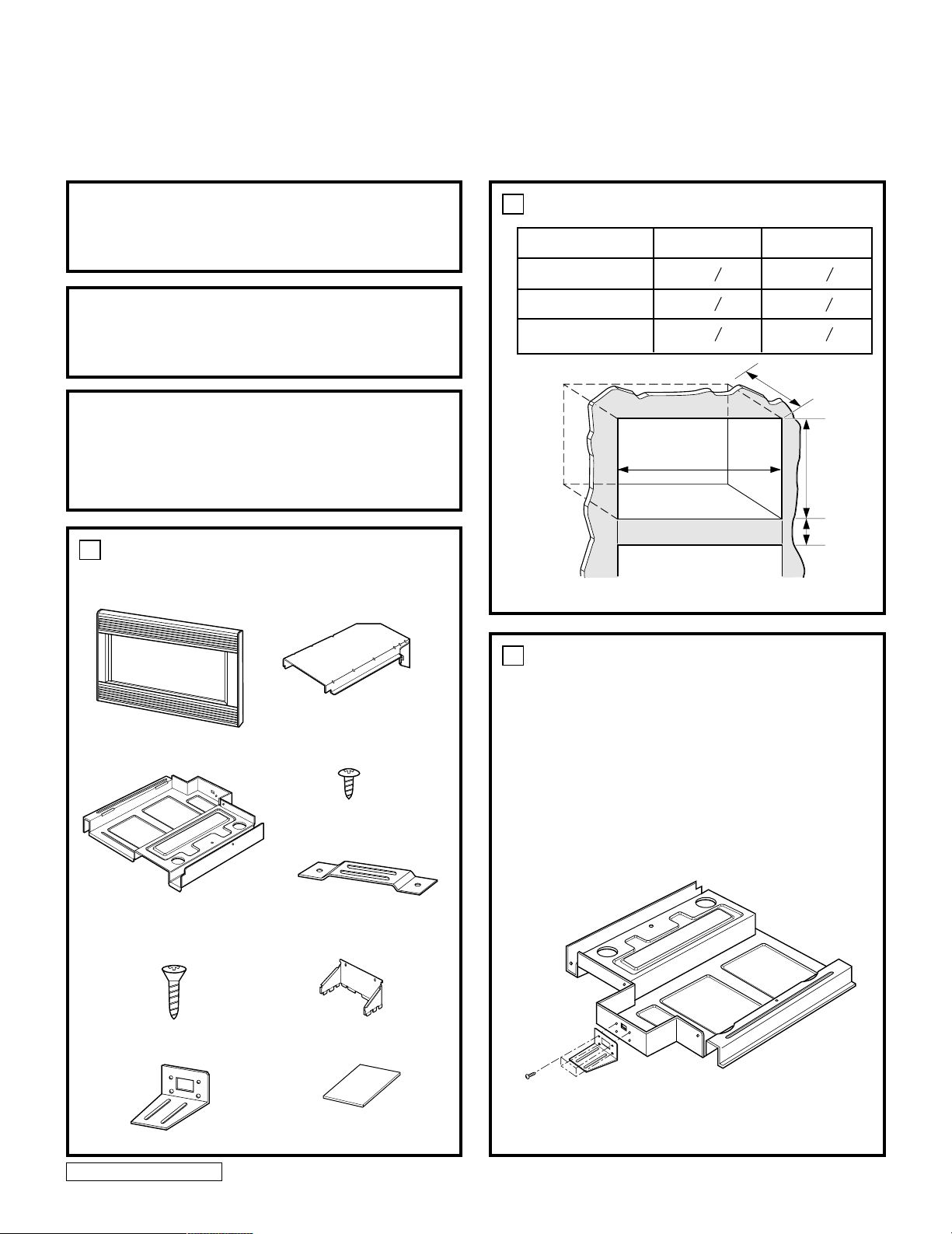
Trim Kit
•
Bottom Duct (1)
•
1" Screws
(4 Req'd 2 Extra)
•
Upper Duct (1)
•
1
/2"
Screws
(16 Req'd 2 Extra)
•
Anti-Tip Bracket (1)
•
Template (1)
•
Rear Duct (1)
•
Bottom Bracket (1)
(KEEP FOR FURTHER REFERENCE)
FOR TRIM-KIT MODELS - 27": AST2780AB, AST2780AW, AST2780AC, AST2780AS
- 30": AST3080AB, AST3080AW, AST3080AC, AST3080AS
• CAUTION: For personal safety, remove
house fuse or open circuit breaker before
beginning installation to avoid severe or
fatal shock injury.
• FOR USE WITH MICROWAVE OVEN
MODELS: ACM1580A/JMC9158AA
• FOR USE OVER ELECTRIC HEAT SOURCE
MODELS:
- 27": AOES2730, AOCS2740, ACO27SE1, JJW8127,
JJW8527, JJW9527
- 30": AOES3030, AOCS3040, JJW8130, JJW8530, JJW9530
1
PARTS INCLUDED
2
CUTOUT DIMENSIONS
27" 30"
1
" 17
Height 17
Width 25
Depth (min.) 23
Width
4
1
" 28
2
3
"23
4
Depth
1
"
4
1
"
2
3
"
4
Height
3" Min.
3
1. Disconnect the microwave oven before
proceeding with installation.
2. Remove any loose items inside the microwave
oven.
3. Fasten the bottom bracket to the bottom duct by
Rear
1
/2
"
screws.
Front
using four
1
/2
" screws (4)
P/No. 12506003
3828W5U0123
1
Page 2
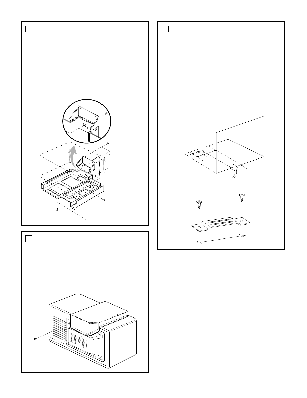
3
4. Install rear duct to the bottom duct with one
screw.
5. Remove the one existing screw from the right
side of the microwave oven.
6. Install bottom duct assembly with six screws as
shown. Fasten bottom duct to the right side of
cabinet with one existing screw.
1
/2
" screws (5)
Procedure Number 4
1
/2
5
"
1. On the cutout floor, mark hole centers for the
anti-tip brackets as shown using the supplied
template. Be sure to align the center line of
template to center line of cutout floor.
2. Drill two holes for anti-tip bracket.
7
/64
"
(use
drill or #35 drill)
3. Install anti-tip bracket onto cutout floor using
1
/2
"
two
screws.
DIMENSIONS:
13
/16
A =
B = 3
C = 20
"
"
1
/16
"
A
B
C
Center Line
Cutout Floor
Existing
1
/2" screws (2)
screw (1)
4
1. Remove the two existing screws from the back
side of the oven.
2. Peel off the backing of double sided tape.
Attach the upper duct on the microwave cabinet.
Press down firmly on duct. Fasten duct to back
side of cabinet with two existing screws as
shown.
Existing
screws (2)
1
/2
" Screws (2)
Anti-Tip Bracket
2
Page 3

6
1. Slide microwave oven part way into cabinet
opening. (Bottom brackets must be flat to the
cutout floor to engage correctly with anti-tip
brackets as shown.)
Bottom Duct
Anti-Tip Assembly
Anti-Tip
Bracket
1
" Screws (2)
/2
Bottom Bracket
2. Plug in the microwave oven.
3. Center the microwave oven within the
cut-out opening and slide the microwave oven
in place, engaging the anti-tip brackets.
(Ensure the microwave oven is accurately
centered)
7
1. Place the trim kit frame over the microwave
oven.
Important Note: Trim kit frame orientation is
important. Orient the frame so that louvers are
sloping downward to the front.
(See Figure Detail of “A”).
2. Make sure the trim kit is level and centered with
respect to microwave oven. Mark four hole
centers through the four mounting holes of the
trim kit.
NOTE: Center the trim kit frame equally on all
four sides.
3. Remove the trim kit and drill four pilot holes.
7
/64
"
(use
4. Attach the trim kit frame by using four 1
Make sure that the orientation is correct as
stated above.
drill or #35 drill)
Pilot Hole
"A"
Cutout Opening
"
screws.
7
/64
"
4. Drill pilot holes (use
drill or #35 drill)
through the positioning flange and then install
1
/2
"
three
screws at the front of the bottom duct
as shown.
Cutout
Opening
1
" Screws (3)
/2
Positioning
Flange
1" Screws (4)
Trim Kit
Figure Detail of "A"
Mounting
Hole
8
1. Your trim kit is now fully installed. Replace any
loose items that have been removed from
inside microwave oven.
2. Please keep this installation instruction for
future reference.
3
Printed in Korea
 Loading...