

Page 1

Service
Commercial Microwave Oven
2001 Models
Service Manual for Amana
®
This Base Manual covers all
Commerical Microwave Ovens.
Refer to individual T echnical Sheet
for information on specific models.
ASE7000
ASE9000
MC23MP
MC23MPT
MC23MPT2
RC17S
RC17SD2
RC17SED
RC22S
RC22S3
RC25S
RC27S
RC30S
This manual is to be used by qualified appliance
technicians only. Amana does not assume any
responsibility for property damage or personal
injury for improper service procedures done by
an unqualified person.
RS2240003
Revision 0
October 2001
Page 2
Important Information
Pride and workmanship go into every product to provide our customers with quality products. It is possible, however,
that during its lifetime a product may require service. Products should be serviced only by a qualified service
technician who is familiar with the safety procedures required in the repair and who is equipped with the proper tools,
parts, testing instruments and the appropriate service manual. REVIEW ALL SERVICE INFORMATION IN THE
APPROPRIATE SERVICE MANUAL BEFORE BEGINNING REPAIRS.
Important Notices for Consumers and Servicers
!
T o avoid risk of serious injury or death, repairs should not be attempted by an unauthorized personal, dangerous
conditions (such as exposure to electrical shock) may result.
!
Amana will not be responsible for any injury or property damage from improper service procedures. If prefroming
service on your own product, assume responsibility for any personal injury or property damage which may result.
To locate an authorized servicer, please consult your telephone book or the dealer from whom you purchased this
product. For further assistance, please contact:
CONSUMER AFFAIRS DEPT. OR 1-319-622-5511
AMANA APPLIANCES, INC. CALL and ask for
AMANA, IOWA 52204 Consumer Affairs
If outside the United States contact:
AMANA
ATTN: CONSUMER AFFAIRS DEPT
AMANA, IOWA 52204, USA
Telephone: (319) 622-5511
Facsimile: (319) 622-2180
TELEX: 4330076 AMANA
CABLE: "AMANA", AMANA, IOWA, USA
WARNING
CAUTION
Recognize Safety Symbols, Words, and Labels
!
DANGER
DANGER - Immediate hazards which WILL result in severe personal injury or death.
!
WARNING
WARNING - Hazards or unsafe practices which COULD result in severe personal injury or death.
!
CAUTION
CAUTION - Hazards or unsafe practices which COULD result in minor personal injury or product or property
damage.
RS2240003 Rev. 0 2
Page 3

Table of Contents
Important Information ....................................................2
Important Product Information .......................................4
Important Safety Information .........................................5
Product Information
Antenna ..................................................................7
Blower/Fan Assembly ............................................7
Splatter Shield........................................................7
Door Interlock and Monitoring Switch .....................7
Transformer High V oltage........................................7
High Voltage Capacitor ...........................................7
High Volt age Diode (Rectifier).................................7
Magnetron ..............................................................7
Thermal Protectors .................................................7
T ouch Panels..........................................................7
Triacs .....................................................................7
Specifications ...............................................................8
Installation
Grounding Instructions.......................................... 10
Unpacking Oven ................................................... 10
Radio Interference................................................. 10
Oven Placement ...................................................10
Care and Cleaning
Recommended Maintenance Schedule ................ 11
Recommended Cleaning Schedule ....................... 11
Cleaning Oven Exterior ......................................... 11
Cleaning Oven Cavity............................................ 11
Oven Racks and Rack Guides.............................. 1 1
Air Filter ............................................................... 11
Discharge Air Vents.............................................. 11
Component T esting Procedures ..................................12
Power T esting Procedure
Power T est (T raditional Test Method).................... 1 9
Traditional Power T est Temperature Chart ............19
Display Diagnostics
Error Codes ..........................................................20
Service T est ................................................................21
Microwave Leakage T est
Equipment............................................................ 23
Procedure For Measuring Radiation Leakage .......23
Measurement With the Outer Case Removed.......23
Measurement With a Fully Assembled Oven ........ 2 3
Record Keeping and
Notification After Measurement ............................23
Troubleshooting
Power up .............................................................. 24
Standby Condition ................................................25
Cook Condition .....................................................26
Disassembly
Door Handle .........................................................27
Outer Door............................................................ 27
Inner Door Assembly ............................................27
Hinge ....................................................................27
Outer Case........................................................... 28
Back Panel ..........................................................28
Splatter Shield...................................................... 2 8
T op T ouch Panel Assembly ..................................28
Side Touch Panel Assembly.................................28
High Volt age Circuit Board ...................................28
Interlock Switch Module .......................................29
Adjustment .................................................... 29
Display Module..................................................... 29
Magnetron ............................................................29
Magnetron, Control, and
Fan Thermal Cutout (TCO)....................................29
Triacs ...................................................................29
Microwave Blower Wheel and Motor .....................30
Fan Blade............................................................. 3 0
Transformer ..........................................................30
Auto Transformer ..................................................30
Capacitor..............................................................30
Fuse .....................................................................31
Power Cord ..........................................................31
Light Socket......................................................... 31
Replacing Oven Light Bulb ...................................31
Component Location........................................ 32-34
Appendix A
Operating Instructions for ASE7000, ASE9000,
RC17S, RC17SD2, RC22S, RC22S3, RC25S,
RC27S, RC30S .................................................. A-2
Operating Instructions for DQ22HSI.................... A-7
Operating Instructions for MC23MP, MC23MPT ,
MC23MPT2 ...................................................... A-12
Amana • 2800 220thTrail • PO Box 8901 • Amana, Iowa • 52204 • Printed in the U.S.A.
3 RS2240003 Rev. 0
Page 4

Important Product Information
!
WARNING
Precautions to be observed before and during
servicing to avoid possible exposure to excessive
microwave energy or electrical shock, disconnect
power to oven.
Do not operate or allow oven to be operated with door
open.
Make the following safety checks on all ovens to be
serviced before activating the magnetron or other
microwave source, and make repairs as necessary:
• Interlock operation
• Proper door closing
• Seal and sealing surfaces (arcing, wear , and other
damage)
• Damage to or loosening of hinges, and latches
• Evidence of dropping or abuse
Before turning on microwave power for any service
test or inspection within the microwave generating
compartments, check the magnetron, waveguide or
transmission line, and cavity for proper alignment,
integrity , and connections.
Any failed or misadjusted components in the
interlock, monitor, door seal, microwave generation,
and transmission systems shall be repaired, replaced
or adjusted by procedures described in this manual
before oven is released to the consumer .
Check microwave leakage to verify compliance with
the federal performance standard should be performed
on each oven prior to releasing to the consumer .
WIRING
Good service practice is to never route wiring over
terminals and/or sharp edges. This applies to any wiring
without regard to the circuit voltage. Wire insulation
material and thickness is designed and regulated for
electrical spacing purpose only , but cannot always be
relied upon because of possible cuts and/or abrasions,
which can occur during servicing.
!
WARNING
T o avoid risk of electrical shock, personal injury or
death; make sure to follow grounding instructions.
Grounding Instructions
!
WARNING
Do not remove grounding prong when installing
grounded appliance in a home or business that does
not have three wire grounding receptacle. Under no
condition is grounding prong to be cut off or removed.
It is the personal responsibility of the consumer to
contact a qualified electrician and have properly
grounded three prong wall receptacle installed in
accordance with appropriate local electrical codes.
Should a two prong adapter plug be required temporarily
it is the personal responsibility of the consumer to have it
replaced with a properly polarizied and grounded three
prong receptacle or the two prong adapter properly
grounded by a qualified electrician in accordance with
appropriate electrical codes.
Servicing of Grounded Products
The standard accepted color coding for grounding wires
is GREEN or GREEN WITH YELLOW STRIPE. These
ground leads are NOT to be used as current carrying
conductors. It is extremely important that the technician
replace any and all grounds prior to completion of the
service call. Under no condition should ground wire be left
off, which can cause a potential hazard to technicians
and consumer .
RS2240003 Rev. 0 4
Page 5

Important Safety Information
!
CAUTION
Do not become exposed to radiation from the
microwave generator or other parts conducting
microwave energy .
Basic design of this microwave oven makes it an
inherently safe device to both use and service. However,
there are some precautions which should be followed
when servicing microwave ovens to maintain this safety .
These are as follows:
1. Always operate unit from an adequately grounded
outlet. Do not operate on a two-wire extension cord.
2. Before servicing unit (if unit is operable) perform
microwave leakage test.
3. Oven should never be operated if door does not fit
properly against seal, hinge/hinge bearings are
damaged or broken; choke is damaged, (pieces
missing, etc.); or any other visible damage can be
noted. Check choke area to ensure that this area is
clean and free of all foreign matter. If any above
problems occur take the following steps:
• Tell the user not to operate the oven.
• Contact Amana immediately .
4. If oven operates with door open and produces
microwave energy , take the following steps:
• Tell the user not to operate the oven.
• Contact Amana immediately .
5. Always have oven disconnected when outer case is
removed except when making "live" tests called for in
the service manual. Do not reach into equipment
area while unit is energized. Make all connections
for the test and check them for tightness before
plugging cord into outlet.
6. Always ground capacitors on magnetron filter box and
H.V . capacitor with an insulated-handle screwdriver
before working in high voltage area of equipment
compartment. Some types of failures will leave a
charge in capacitors and the discharge could cause a
reflex action which could make you injure yourself.
7. In the area of the transformer, capacitor , diode, and
magnetron there is HIGH VOL T AGE. When unit is
operating, keep area clean and free of anything which
could possibly cause an arc or ground, etc.
8. DO NOT for any reason defeat interlock switches,
there is no valid reason for this action at any time;
nor will it be condoned by Amana.
9. Microwave ovens should never be operated with:
• Any components removed and/or bypassed
• Any of the safety interlocks are found to be
defective
• Any of the seal surfaces which are failing, missing
or damaged
10.To ensure that unit does not emit excessive
microwave leakage and to meet Department of Health
and Human Services guidelines check oven for
microwave leakage using Narda Model 81 10B or
Holaday HI1501, HI1510, HI1710 leakage monitor as
outlined in instructions. Maximum leakage level
allowed is 4mw/cm
1 1.If servicer encounters an emission reading over
4mw/cm2, servicer is to cease repair and contact
Amana Service Department immediately for further
direction. Amana will contact the proper Government
Agency upon verification of test results.
12.Install or locate this equipment ONLY in accordance
with the installation instructions in this manual.
13.Some products such as whole eggs and sealed
containers – for example, closed glass jars – may
explode and SHOULD NOT be HEATED in this
equipment.
14.Use this equipment ONLY for its intended use as
described in this manual. Do not use corrosive
chemicals or vapors in this equipment. This type of
equipment is specifically designed to heat or cook. It
is not designed for industrial or laboratory use.
15.As with any equipment, CLOSE SUPERVISION is
necessary when used by CHILDREN.
16.DO NOT operate this equipment if it has a damaged
cord or plug, if it is not working properly , or if it has
been damaged or dropped.
17.This equipment, including power cord, must be
serviced ONLY by qualified service personnel. Special
tools are required to service equipment. Contact
nearest authorized service facility for examination,
repair, or adjustment.
18.DO NOT cover or block any openings on the
equipment.
19.DO NOT store this equipment outdoors. DO NOT use
this product near water – for example, near a kitchen
sink, in a wet basement or near a swimming pool,
and the like.
20.DO NOT immerse cord or plug in water.
21.Keep cord AWA Y from HEATED surfaces.
22.DO NOT let cord hang over edge of table or counter.
2
.
5 RS2240003 Rev. 0
Page 6
Important Safety Information
!
CAUTION
T o avoid risk of personal injury or death of fire in the oven cavity:
• DO NOT overcook food. Carefully attend equipment if paper , plastic or other combustible materials are placed
inside the equipment to facilitate cooking.
• Remove wire twist-ties from paper or plastic bags before placing bag in equipment.
• KEEP equipment DOOR CLOSED, turn equipment off, and disconnect the power cord or shut off power at the
fuse or circuit breaker panel if materials inside the equipment should ignite. Fire may spread if door is opened.
• DO NOT use the cavity for storage purposes. DO NOT leave paper products, cooking utensils or food in the
cavity when not in use.
!
CAUTION
To avoid personal injury or property damage, observe the following:
1. Briskly stir or pour liquids before heating with
microwave energy to prevent spontaneous boiling
or eruption. Do not overheat. If air is not mixed into
a liquid, liquid can erupt in equipment or after
removal from equipment.
2. Do not deep fat fry in equipment. Fat could overheat
and be hazardous to handle.
3. Do not cook or reheat eggs in shell or with an
unbroken yolk using microwave energy. Pressure
may build up and erupt. Pierce yolk with fork or
knife before cooking.
4. Pierce skin of potatoes, tomatoes, and similar
foods before cooking with microwave energy.
When skin is pierced, steam escapes evenly.
5. Pop popcorn in microwave mode only. If
equipment is preheated or hot, allow equipment to
cool before popping popcorn or bag may ignite.
6. Do not use regular cooking thermometers in
equipment when cooking. Most cooking
thermometers contain mercury and may cause an
electrical arc, malfunction, or damage to
equipment.
7. Do not heat baby bottles in equipment.
8. Do not use metal utensils in equipment except
when recommended by microwave food
manufacturers. Heat food in containers made of
glass or china if possible.
9. Never use paper, plastic or other combustible
materials that are not intended for cooking. If
equipment temperature is high, material may
ignite.
10. Do not use paper towels which contain nylon
or other synthetic fibers. Heated synthetics could
melt and cause paper to ignite.
11. Do not heat sealed containers or plastic bags
in equipment. Food or liquid could expand quickly
and cause container or bag to break. Pierce or
open container or bag before heating.
12. Racks, utensils, and equipment surfaces may
become hot during or after use. Use utensils or
protective clothing, like pan grips or dry oven mitts,
when necessary to avoid burns.
13. Do not use rack position if rack hook breaks.
Replace broken hooks immediately.
14. Do not unplug equipment immediately after use.
Internal fan must cool equipment to avoid damage
of electrical components.
RS2240003 Rev. 0 6
Page 7
Product Information
Antenna
Distributes microwave energy throughout the cavity.
Blower/Fan Assembly
Circulates cooling air throughout the microwave oven
compartment and cavity .
Splatter Shield
Covers and protects the antenna assembly .
Door Interlock and Monitoring Switch
NOTE: When the line fuse is blown the Interlock Switch
Assembly must be replaced.
Interlock switch (assembly) mounts behind oven cavity
front bulkhead. It is actuated by door hook and guide
attached to the door .
Monitoring switch (contacts 7 and 8) is actuated by the
door guide.
The secondary interlock switch (contacts 2 and 3) and
primary interlock switch (contacts 4 and 5) are actuated
by the door hook.
The secondary interlock switch is in series with the
interlock monitoring switch in the monitor circuit.
If a malfunction occurs in the secondary interlock when
door opens, current will flow through the monitor switch
causing the oven fuse to open.
If a faulty door interlock switch has allowed current
through the monitor switch, the switch assembly must be
replaced (see interlock switch testing) before replacing
fuse.
Transformer High Voltage
High voltage transformer is used in this unit, which
supplies high voltage A.C. for operation of the magnetron
tube.
High Voltage Capacitor
Doubles the A.C. output voltage from the high voltage
transformer.
High V olt age Diode (Rectifier)
Is connected at the output side of the high voltage
capacitor. It changes voltage from A.C. to D.C. It
passes current in one direction and blocks it in the other.
Also called a rectifier.
Magnetron
With filament voltage and high D.C. voltage from the
output of the H.V . capacitor, diode junction the
magnetron will put out an electomagnetic radio
frequency of 2450 MHz to heat the food load in the
oven.
Thermal Protectors
At a predetermined temperature the thermal cut-outs will
open or close. The oven will indicate an error code in the
display , initiate cooling fan operation, or prevent the
generation of microwave energy .
• Magnetron thermal cut-out is mounted directly on the
body of the magnetron.
• Oven cavity thermal cutout is mounted inside the
exhaust duct.
DANGER
!
To avoid severe personal injury or death avoid
contacting any high voltage parts. The capacitors are
at high voltage (4000 volt) potential and it is extremely
important that they be grounded before handling.
Touch Panels
Allows consumer operation and programming of oven.
Triacs
Triacs are controlled by high volt age circuit boards.
Triacs control one side of the power line going to the
high voltage power transformer .
• Microwave triacs are mounted on back of oven cavity
panel.
7 RS2240003 Rev. 0
Page 8
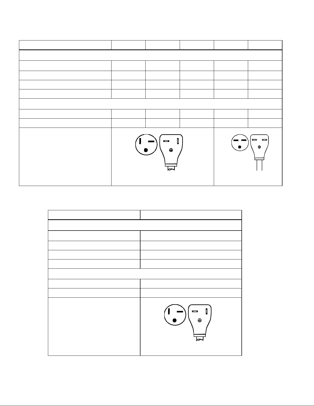
Specifications
ASE7000, ASE9000, RC17S, RC17SD2, RC22S, RC22S3, RC25S, RC27S, RC30S
Nominal Microwave Energy (IEC705) 1700 W 2200 W 2500 W 2700 W 3000 W
Power Source
Voltage AC 208/230 208/230 208/230 208/230 208/230
Frequency 60 Hz 60 Hz 60 Hz 60 Hz 60 Hz
Amperage 20 A 20 A 20 A 30 A 30 A
Single Phase, 3-wire ground X X X X X
Power
Frequency 2450 MHz 2450 MHz 2450 MHz 2450 MHz 2450 MHz
Power Consumption 2700 W 3200 W 3700 W 4100 W 4400 W
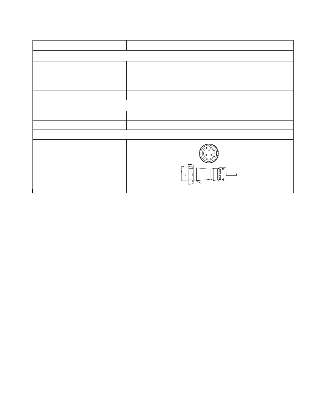
Receptacle and Plug
DQ22HSI
NEMA 6-20P NEMA 6-30P
Nominal Microwave Energy (IEC705) 2200 W
Power Source
Voltage AC 208/230
Frequency 60 Hz
Amperage 20 A
Single Phase, 3-wire ground X
Power
Frequency 2450 MHz
Power Consumption 3200 W
Receptacle and Plug
RS2240003 Rev. 0 8
NEMA 6-20P
Page 9
Specifications
MC23MP, MC23MPT, MC23MPT2
Nominal Microwave Energy (IEC705) 2200 W
Power Source
Voltage AC 208/230
Frequency 60 Hz
Amperage 20 A
Single Phase, 3-wire ground X
Power
Frequency 2450 MHz
Power Consumption 3200 W
Receptacle and Plug
MP
20 Amp Hubbell
320P6WM2
9 RS2240003 Rev. 0
Page 10
Installation
Grounding Instructions
NOTE: Do not under any circumstances cut or remove
grounding prong from the plug or bend power prongs to fit
receptacle other than one shown for your equipment.
Such abuse of the plug can result in electrical shock or
overheating.
!
WARNING
Improper use of grounding plug can result in a risk of
electrical shock or death.
This equipment MUST be grounded. In the event of an
electrical short circuit, grounding reduces risk of electric
shock by providing an escape wire for electric current.
This oven is equipped with a cord having grounding wire
with a grounding plug. Plug must be plugged into an
outlet that is properly installed and grounded. DO NOT
use a two-prong adapter .
Consult a qualified electrician or servicer if grounding
instructions are not completely understood or if doubt
exists as to whether the equipment is properly grounded.
Do not use an extension cord. If product power cord is
too short, have a qualified electrician install an
appropriate receptacle. This equipment should be
plugged into a separate 60 Hz circuit with the appropriate
electrical rating label. When the oven is on a circuit with
other equipment, an increase in cooking times may be
required and fuses can be blown.
Radio Interference
Microwave operation may cause interference to radio,
television or a similar oven. Reduce or eliminate
interference by doing the following:
• Clean door and sealing surfaces of oven according to
instructions in Care and Cleaning section.
• Place radio, television, etc. as far as possible from
oven.
• Use a properly installed antenna on radio, television,
etc. to obtain stronger signal reception.
Oven Placement
• Do not install oven next to or above source of heat,
such as pizza oven or deep fat fryer. This could cause
microwave oven to operate improperly and could
shorten life of electrical parts.
• Do not block or obstruct oven filter . Allow access for
cleaning.
• Install oven on level countertop surface.
• Place warning label in a conspicuous place close to
microwave oven.
• Outlet should be located so that plug is accessible
when oven is in place.
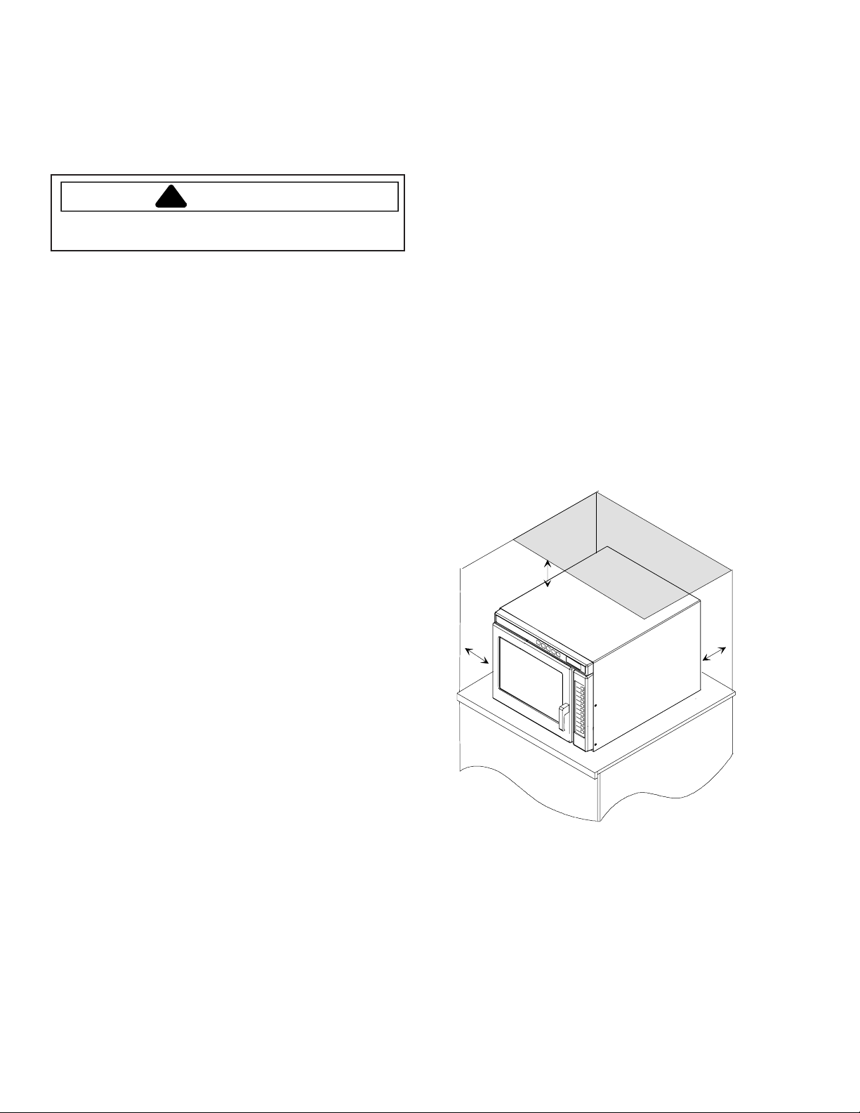
A
Unpacking Oven
• Inspect oven for damage such as dents in door or
inside oven cavity .
• Report any dents or breakage to source of purchase
immediately.
• Do not attempt to use oven if damaged.
• Remove all materials from oven interior.
• If oven has been stored in extremely cold area, wait a
few hours before connecting power.
B
A
A—Allow at least 7 " (17.8 cm) of clearance around
top and sides of oven. Proper air flow around oven
cools electrical components. With restricted air
flow, oven may not operate properly and life of
electrical parts is reduced.
B—Allow at least 2 9/16 " (6.5 cm) between air
discharge on back of oven and back wall.
RS2240003 Rev. 0 10
Page 11
Care and Cleaning
Clean oven frequently to maximize oven life, performance,
and efficiency . A dirty oven cooks inefficiently because
moisture, spills, and grease absorb microwave energy .
WARNING
!
T o avoid electrical shock, severe personal injury or
death; disconnect power to unit before cleaning.
CAUTION
!
T o prevent personal injury; handle utensils, racks, and
door with care. Utensils, racks, and door may become
hot during operation.
Recommended Maintenance Schedule
Schedule Maintenance Cleaning (Not Covered Under
Warranty)
Recommended Cleaning Schedule
Schedule Several Daily Cleanings
• Clean interior , exterior, and door according to
instructions.
• If possible, clean spills immediately .
• Clean air filter and air vents regularly to prevent
overheating.
• Wipe dry after cleaning.
Cleaning Oven Cavity
Rub vigorously with nylon scouring pad to loosen debris.
Wipe clean with warm, damp clean cloth.
• Use only a plastic putty knife, nylon scouring pad or
equivalent, to aid in removing soil or build-up from the
oven interior.
• Do not use knife, metal utensil, or steel wool pad to
remove baked on material.
Air Filter
Air filter must be cleaned regularly to prevent overheating
of oven. The air filter is located directly below the oven
door.
1. Remove the filter retaining screws, located on the
outside edges of the filter.
2. Remove the air filter.
3. Wash filter in a mild detergent solution made with
warm water.
4. Rinse and dry thoroughly .
5. Replace filter and screws.
NOTE: Clean air filter regularly to prevent overheating,
which may damage oven.
Discharge Air Vents
Check for a buildup of cooking vapors along discharge
louvers in back of oven. Clean air vent with damp cloth to
ensure proper airflow . Dry thoroughly.
Clean After Use
• Clean exterior according to Cleaning Oven Exterior
instructions.
• Clean oven cavity according to Cleaning Oven Cavity
instructions.
• Wipe dry after cleaning.
Cleaning Oven Exterior
Clean door and other exterior surfaces with a clean cloth,
sponge or nylon pad using a mild detergent diluted in
warm water. Use commercial degreasers if heavily soiled.
• Do not use harsh or abrasive cleaners or cleaners
containing ammonia.
• Do not use water pressure type cleaning systems.
• Remove excess water from cloth before wiping oven.
11 RS2240003 Rev. 0
Page 12
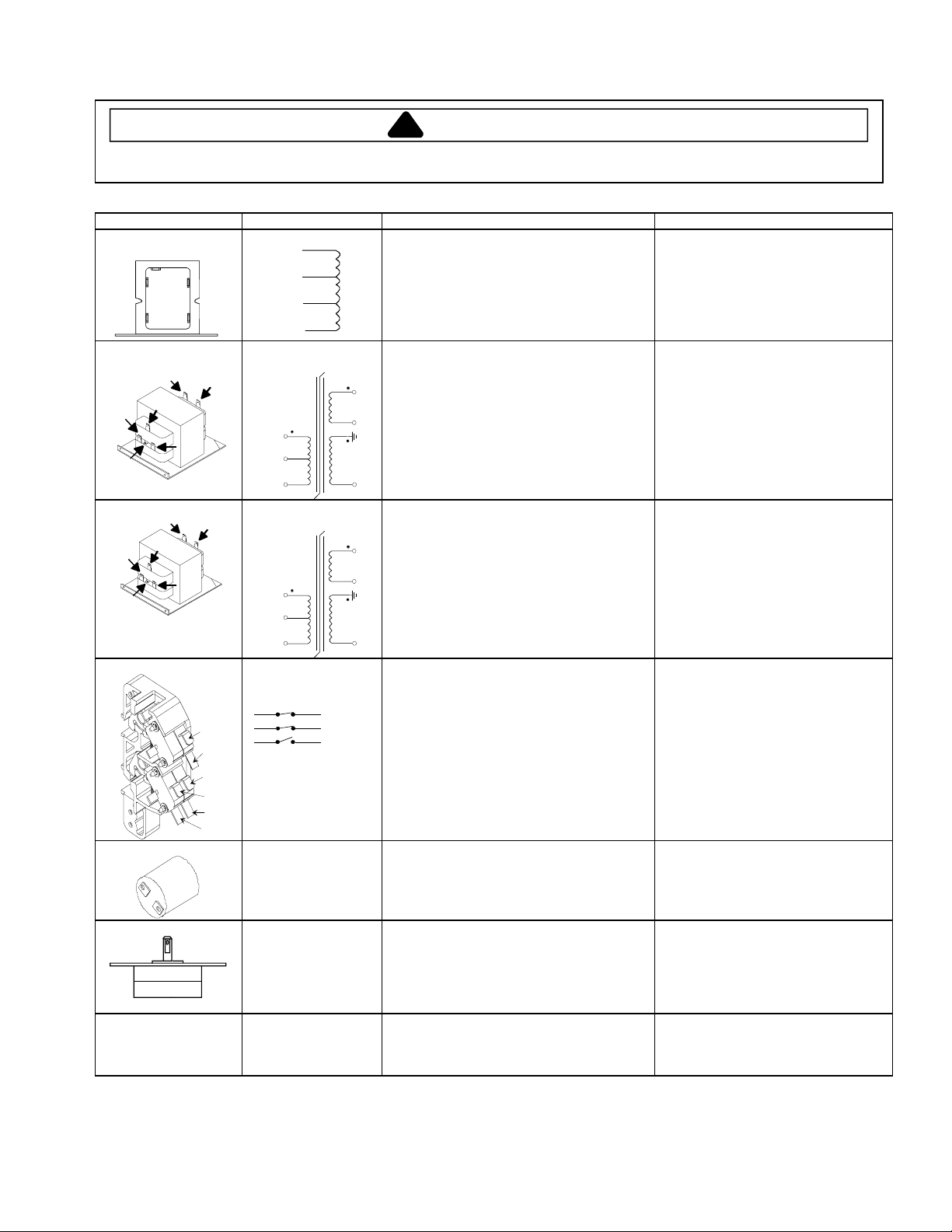
Component Testing Procedures
!
WARNING
To avoid risk of electrical shock, personal injury or death; disconnect power to oven and discharge capacitor
before servicing, unless testing requires power.
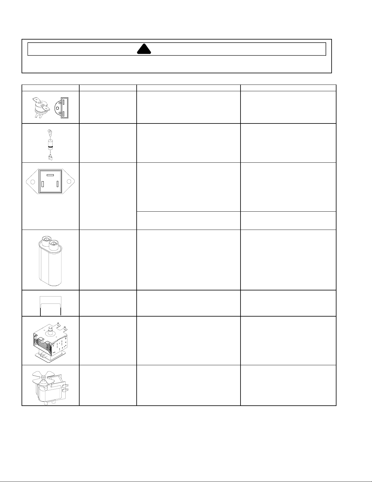
Illustration Component Test Results
Thermal cutout Disconnect all wires from TCO.
Diode
Triac
MT2
MT1 GATE
Triac 1 (center)
Triac 2 (left)
Triac 3 (right
Capacitor
Measure resistance across terminals.
Magnetron TCO...................................
Cavity TCO ..........................................
Discharge Capacitor
Remove diode lead from capacitor and
connect ohmmeter.
Reverse leads for second test.
Resistance Check
Disconnect wires to triac.
Measure resistance from:
MT1 toMT2 .........................................
MT1 toGate.........................................
MT2 toGate.........................................
All terminals to ground.........................
Voltage Check
Measure voltage from:
MT1toGate
Discharge Capacitor
Open at 300°F (149°C) and closed at
257°F (125°C)
Opens at 262°F (128°C)
Infinite resistance should be measured
in one direction and 50KΩ or more in
the opposite direction.
NOTE: Ohmmeter must contain a
battery of 6 volts minimum.
Caution - Do not operate oven with
wire to terminal MT2 removed.
Infinite
Approximately 60 Ω
Infinite
Infinite
0.8 VAC when energized. If no
voltage, check H.V. board and wiring.
Some unit may use
more then one type of
capacitor, Refer to
Parts Manual for
correct capacitor
quantity.
Snubber assembly Disconnect wires to snubber.
Magnetron
Blower motor Remove all wires from motor.
Remove wires from capacitor terminals
and connect ohmmeter, set on highest
resistance scale to terminals.
Also check between each terminal and
capacitor case.
Measure resistance across terminals........ Infinite
Discharge Capacitor
Remove wires from magnetron and
connect ohmmeter to terminals. Also
check between each terminal and ground.
Measure resistance across coil.................
Between Terminals: Meter should
momentarily deflect towards zero then
return to over 5 MΩ.Ifnodeflection
occurs, or if continuous deflection
occurs, replace capacitor.
Terminal to Case: Infinite resistance
Between Terminals: Less than 1 Ω
Each terminal to ground measures
Infinite resistance.
Note: This test is not conclusive. If
oven does not heat and all other
components test good replace the
magnetron and retest.
Approximately 25 Ω
RS2240003 Rev. 0 12
Page 13
Component Testing Procedures
208 V
230 V
120 V
!
WARNING
To avoid risk of electrical shock, personal injury or death; disconnect power to oven and discharge capacitor
before servicing, unless testing requires power.
Illustration Component Test Results
COM
0V
COM
208
COM
208
Auto Transformer
230
208
120
0
Transformer
6
4
230
5
COM
208 VAC
230 VAC
Transformer
6
5
4
230
COM
208 VAC
230 VAC
Interlock switch
Discharge Capacitors
Remove all wires from terminals.
Measure resistance from:
230 V to 0 V............................................
208 V to 0 V............................................
120 V to 0 V............................................
Discharge Capacitor
Remove all wires from terminals.
5
Measure resistance from:
230 to COM.............................................
6
208 to COM.............................................
230 to Ground.........................................
208 to Ground.........................................
Terminal 5 to 6........................................
4
Terminal 4 to Ground ..............................
Disconnect wires to switch.
Approximately 38 Ω
Approximately 37 Ω
Approximately 25 Ω
Less than 1 Ω
Less than 1 Ω
Infinite
Infinite
Less than 1 Ω
Approximately 65 Ω
Less than 1.1 Ω
Less than 1 Ω
Infinite
Infinite
Less than 1 Ω
Approximately 70 Ω
7
8
2
4
3
5
Refer to Parts Manual
for proper power cord
part number.
Door Closed
2
4
7
Secondary
3
Primary
5
Monitor
8
With door open measure resistance from:
Terminal 2 to 3........................................
Terminal 4 to 5........................................
Terminal 7 to 8........................................
Infinite
Infinite
Indicates continuity
With door closed measure resistance from:
Indicates continuity
Indicates continuity
Infinite
and screwed in.
Lamp receptacle
(some models)
Terminal 2 to 3........................................
Terminal 4 to 5........................................
Terminal 7 to 8........................................
Test continuity of receptacle terminals. Indicates continuity if bulb is good
Antenna motor Remove all wires from terminals.
Measure resistance from:
Terminal to terminal....................................
Approximately 12K Ω
Power cord Measure resistance of wires. Continuity should be indicated on
each wire.
Verify polarity and grounding.
13 RS2240003 Rev. 0
Page 14
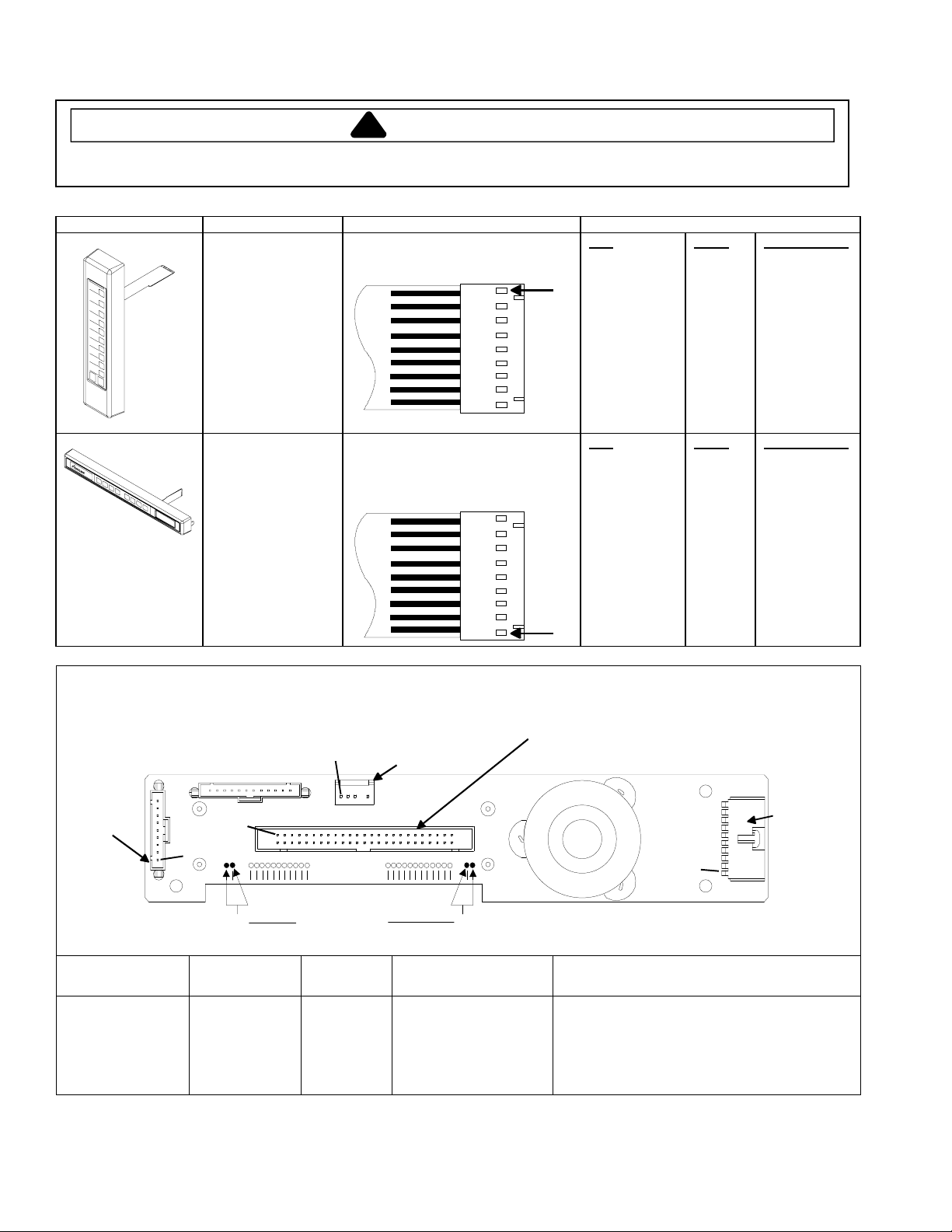
Component Testing Procedures
1
1
!
WARNING
To avoid risk of electrical shock, personal injury or death; disconnect power to oven and discharge capacitor
before servicing, unless testing requires power.
Illustration Component Test Results
Side touch panel
Top touch panel Removal of touch panel is required to
Continuity is indicated as 100 Ω and
below.
perform test.
Continuity is indicated as 100 Ω and
below.
Pad
1
2
3
4
5
6
7
8
9
0
Start
Stop/Reset
Pad
Time Entry
Power Level
Stage
Program Save
Quantity
Menu
Hidden Pad
Trace
3&5
3&6
3&7
3&8
3&9
4&5
4&6
4&7
4&8
4&9
5&6
6&9
Trace
5&7
5&8
5&9
6&7
6&8
7&9
8&9
Measurement
Continuity
Continuity
Continuity
Continuity
Continuity
Continuity
Continuity
Continuity
Continuity
Continuity
Continuity
Continuity
Measurement
Continuity
Continuity
Continuity
Continuity
Continuity
Continuity
Continuity
Display board
Side
Touch
Panel
Pin 1
Pin 1
Connector
J5
A B
Test Points
Function Test Set-Up Meter
Input to Display
Board
At Display
Board
Pin 1
Interlock
Connector
H.V. board
Connector
J1
J6
Pin 1
Probe Placement Results
Setting
Volts Test points A and B 3.0 VAC
If voltage is present and no displayis
indicated, replace display board.
If no voltage is present, check wire
harness connections and H.V. board.
J4
Top
Touch
Panel
Connector
RS2240003 Rev. 0 14
Page 15
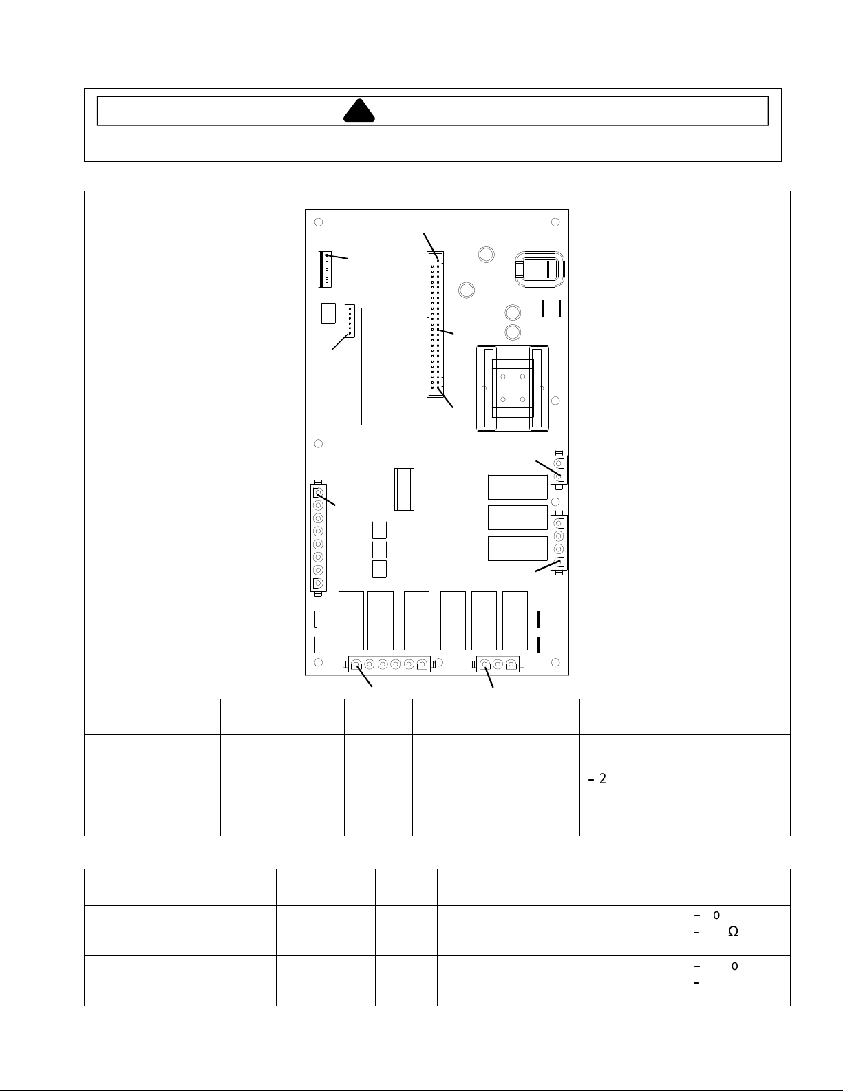
Component Testing Procedures
!
WARNING
To avoid risk of electrical shock, personal injury or death; disconnect power to oven and discharge capacitor
before servicing, unless testing requires power.
H.V. board
J8
Pin 1
J6
Pin 1
J7
Pin 1
Pin 1
J5
E1
E2E3
Pin 28
Pin 50
J1
Pin 1
E7
E6
J4
Function Test Set-Up Meter
Pin 1
J3
Pin 1Pin 1
Probe Placement Results
J2
E4
E5
Setting
Input to H.V. board At H.V. board Volts J1 pin 1 (Brown wire)
&J1pin2(Whitewire)
Output to display
board
Disconnect
J5 connector,
Volts J5 pin 28 &
J5 pin 50
blower runs
continuously
NOTE: For the following test, place oven in Service Test Mode (see page 21).
Relay Function Test Set-Up Meter
Probe Placement Results
Setting
K1 at
230 VAC
line voltage
K2 at
208 VAC
line voltage
Blower motor
Antenna motor
Cavity light
Blower motor
Antenna motor
Cavity light
Disconnect
J2 connector
Disconnect
J2 connector
Ohms J1 pin 1 (Brown wire)
&J2pin4
Ohms J1 pin 1 (Brown wire)
&J2pin3
Line voltage
-
24 VDC
Testmode5off-no continuity
-
Testmode5on
<1Ω
Testmode5off-no continuity
-
Testmode5on
<1Ω
15 RS2240003 Rev. 0
Page 16
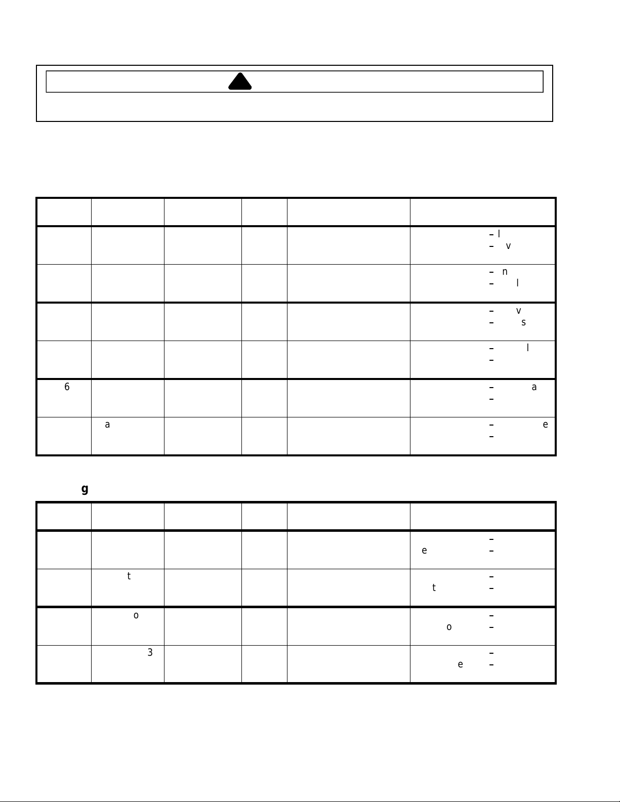
Component Testing Procedures
!
To avoid risk of electrical shock, personal injury or death; disconnect power to oven and discharge capacitor
before servicing, unless testing requires power.
WARNING
H.V. Board − Relay Test
Three Magnetron Models
Relay Function Test Set-Up Meter
Setting
K8
K9 Magnetron 1
K4
K5 Magnetron 2
K6
K7 Magnetron 3
Magnetron 1
(Top rear) at
230 VAC
(Top rear) at
208 VAC
Magnetron 2
(Top front) at
230 VAC
(Top front) at
208 VAC
Magnetron 3
(Bottom) at
230 VAC
(Bottom) at
208 VAC
All wires
connected to
H.V. board
All wires
connected to
H.V. board
All wires
connected to
H.V. board
All wires
connected to
H.V. board
All wires
connected to
H.V. board
All wires
connected to
H.V. board
VAC E2 (Black wire)
VAC E2 (Black wire)
VAC E5 (Red wire)
VAC E5 (Red wire)
VAC J4 pin 4 (Black wire)
VAC J4 pin 4 (Black wire)
Probe Placement Results
Testmode1off-line voltage
&J4pin2(Redwire)
&J4pin1(Whitewire)
&J3pin1(Graywire)
& J3 pin 3 (Orange wire)
&J4pin6(Blackwire)
&J4pin5(Brownwire)
Testmode1on
Testmode1off-line voltage
Testmode1on
Testmode2off-line voltage
Testmode2on
Testmode2off-line voltage
Testmode2on
Testmode3off
Testmode3on
Testmode3off-line voltage
Testmode3on
-
0volts
-
0volts
-
0volts
-
0volts
-
line voltage
-
0volts
-
0volts
Two Magnetron Models
Relay Function Test Set-Up Meter
Setting
K8
K9 Magnetron 1
K6
K7 Magnetron 3
RS2240003 Rev. 0 16
Magnetron 1
(Top rear) at
230 VAC
(Top rear) at
208 VAC
Magnetron 3
(Bottom) at
230 VAC
(Bottom) at
208 VAC
All wires
connected to
H.V. board
All wires
connected to
H.V. board
All wires
connected to
H.V. board
All wires
connected to
H.V. board
VAC E5 (Red wire)
VAC E5 (Red wire)
VAC J4 pin 4 (Black wire)
VAC J4 pin 4 (Black wire)
Probe Placement Results
Testmode1off
&J4pin2(Redwire)
&J4pin1(Whitewire)
&J4pin6(Blackwire)
&J4pin5(Brownwire)
Testmode1on
Testmode1off-line voltage
Testmode1on
Testmode3off
Testmode3on
Testmode3off-line voltage
Testmode3on
-
line voltage
-
0volts
-
0volts
-
line voltage
-
0volts
-
0volts
Page 17

Component Testing Procedures
!
To avoid risk of electrical shock, personal injury or death; disconnect power to oven and discharge capacitor
before servicing, unless testing requires power.
WARNING
Three Magnetron Models
#3
#1
#2
#2
#1
#2
#1
#3
#2
H.V. System # 1 H.V. System # 2 H.V. System # 3
Top Rear Magnetron
Center Transformer
Bottom Center Capacitor
Diode
Center Triac
Top Front Magnetron
Left Transformer
Top Left Capacitor
Diode
Left Triac
#3
#3
#1
Bottom Magnetron
Right Transformer
Right Capacitor
Diode
Right Triac
17 RS2240003 Rev. 0
Page 18

Component Testing Procedures
!
To avoid risk of electrical shock, personal injury or death; disconnect power to oven and discharge capacitor
before servicing, unless testing requires power.
WARNING
Two Magnetron Models
#1
#1
#1
#3
#3
#1
H.V. System # 1 H.V. System # 3
Top Rear Magnetron
Left Transformer
Top Capacitor
Diode
Left Triac
#3
Bottom Magnetron
Right Transformer
Bottom Capacitor
Diode
Right Triac
#3
RS2240003 Rev. 0 18
Page 19

Power Testing Procedure
!
To avoid risk of electrical shock, personal injury or death; disconnect power to oven and discharge capacitor
before servicing, unless testing requires power.
WARNING
Power Test (Traditional Test Method)
Test equipment required is Amana power test kit R0157397 (Fahrenheit), or
Menumaster power test kit M95D5 (Celsius).
1. Fill the plastic container to the 1000 ml. line with cool tap water.
2. Using the thermometer; stir the water, measure, and record the water temperature.
Initial water temperature should be approximately 60°F(16°C).
3. Place container on the center of the oven shelf and heat the water for
33 seconds for ovens with more than 1550 watts or 63 seconds for ovens with less than 1550 watts.
NOTE: Use a watch second hand, not the oven timer.
4. Stir the water, measure and record the temperature of the water after heating time is complete.
5. Subtract the starting water temperature (Step 2), from the ending water temperature (Step 4) to obtain the
temperature rise (∆T).
6. See the Traditional Power Test Temperature Chart below.
NOTES: •The IEC-705 test method requires precision measurements and equipment. It is not practical to perform
the IEC test in the field. To convert the traditional power test results to the approximate IEC-705 rating,
take the traditional power test results and add 150 watts per magnetron for the unit being tested.
Example: 1400 watts output using the traditional power test for model RC17S
watts (2 magnetrons X 150 watts)
+ 300
1700 Approximate IEC-705 results
•Always perform power test three times for accuracy, changing the water after each test is performed.
•Variation or errors in the test procedure will cause a variance in the temperature rise. Additional power
tests should be made if temperature rise appears marginal.
•Low line voltage will cause lower temperature rise.
Traditional Power Test Temperature Chart
THIRTY-THREE (33) SECONDS run time chart for units more than 1550 Watts cooking power
Fahrenheit Celsius
∆T Cooking ∆T Cooking ∆T Cooking ∆T Cooking
(°F) Power Output (°F) Power Output (°C) Power Output (°C) Power Output
16 .......1240 27 ...........2092 9.......... 1260 15.............. 2100
17 .......1317 28 ...........2170 9.5....... 1330 15.5........... 2170
18 .......1395 29 ...........2247 10........ 1400 16.............. 2240
19 .......1472 30 ...........2325 10.5..... 1470 16.5........... 2310
20 .......1550 31 ...........2402 11........ 1540 17.............. 2380
21 .......1627 32 ...........2480 11.5..... 1610 17.5........... 2450
22 .......1705 33 ...........2557 12........ 1680 18.............. 2520
23 .......1782 34 ...........2635 12.5..... 1750 18.5........... 2590
24 .......1860 35 ...........2712 13........ 1820 19.............. 2660
25 .......1937 36 ...........2790 13.5..... 1890 19.5........... 2730
26 .......2015 37 ...........2867 14........ 1960 20.............. 2800
14.5.....2030 20.5........... 2870
19 RS2240003 Rev. 0
Page 20

Display Diagnostics
!
WARNING
To avoid risk of electrical shock, personal injury, or death, disconnect power to oven and discharge capacitor
before servicing, unless testing requires it.
CAUTION
!
All repairs as described in this troubleshooting section are to be performed only after the caution procedures one through
eight listed below have been followed.
1. Check grounding before checking for possible causes.
2. Be careful of the high voltage circuit.
3. Discharge high voltage capacitor.
4. When checking the continuity of the switches or the high voltage transformer, disconnect one lead wirefrom these parts
and then check continuity with the AC plug removed. To do otherwise may result in a false reading or damage to your
meter.
5. Do not touch any parts of the circuitry on the P.C. Board circuit since static electric discharge may damage this control
panel. Always touch yourself to ground while working on this panel to discharge any static charge in your body.
6. 208/230 VAC is present in the high voltage circuit board, power relay and primary circuit of low voltage transformer.
7. When troubleshooting, be cautious of possible electrical hazard.
8. When testing convection operation, convection fan may start at any time or if oven is hot.
Error Codes
During operation, the display may show the following service codes:
NOTE: Before scheduling service for any error codes, instruct customer to unplug oven for 1 minute,
reconnect power, and retest. If unit operates properly, no service call is required.
Display Description Corrective Action
Err1 Failed H.V. Board Replace H.V. board.
Err2 Failed H.V. Board
Failed Touch Panel
Err3 Failed H.V. Board
Failed Touch Panel
Err4 Failed H.V. Board Replace H.V. board.
Err5 Failed Touch Panel
Err6 Failed H.V. Board Replace H.V. board.
HOT
Door Door Interlock Primary Switch
Replace H.V. board.
Replace Touch Panel.
Replace H.V. board.
Replace Touch Panel.
NOTE: If Touch Panel is pressed for more than 30 seconds,
this error code will appear.
1. Disconnect oven from power supply.
2. Disconnect side touch panel connector from display board
(J5).
3. Reconnect oven to power supply.
4. If “Err5” reappears after 30 seconds, replace top touch
panel.
5. If “Err5” does not reappear after 30 seconds, replace side
touch panel.
• Open TCO (magnetron).
• Blower motor inoperative.
• Restricted air filter.
• H.V. board inoperative.
• High ambient temperature.
• Oven operated empty or with light loads.
• Broken or loose wire.
• Verify latch mechanism moves freely on door.
• Verify J1 connector on display board is properly seated.
• Test interlock switch assembly and perform door adjustment
if necessary.
• Replace interlock switch assembly.
RS2240003 Rev. 0 20
Page 21

Service Test
!
WARNING
To avoid risk of electrical shock, personal injury or death; disconnect power to oven and discharge capacitor
before servicing, unless testing requires power.
NOTE: Unit must be in OFF condition
or
INITIAL power up mode.
QTY
1
2
3
4
CM
STG
ITEM POWER
1
2
3
4
CM
NOT READY
PREHEAT STANDBY
LMT
QTY
PREHEAT STANDBY
NOT READ Y
LMT
POWER
COOK
LEVEL
COOK
LEVEL
STG
ITEM
To Enter Service Test Mode, oven door must be closed.
NOTE: Pads will not beep when accessing Service Test Mode.
To EXIT Service Test Mode press STOP/RESET pad.
MC units
1
BREAKFAST
2
REG MENU
3
PREP
4
MISC
Hidden
Pad
MENU
Press Hidden Pad
as indicated above
on touch panels.
Press
0=Deactivated
1=Activated
Then
DQ22HSI
Hidden
Pad
MENU
RC units
Hidden
Pad
1 3 5 7 9
Display
ITEM
STG
QTY
1
2
3
4
CM
PREHEAT STANDBY
LMT
NOT READY
QUANTITY
POWER
COOK
LEVEL
ITEM
CM
Component Evaluation
STG
QTY
1
2
3
4
LMT
Indicates
Service
Mode
WDYRC2
Hidden
Pad
PREHEAT STANDBY
NOT READY
POWER
COOK
LEVEL
High Voltage System # 1
1
Toggles Magnetron 1
(Top Rear) ON/OFF.
High Voltage System# 2
2
Toggles Magnetron 2
(Top Front) ON/OFF.
NOTE:
Not Applicable on Two Magnetron models:
DQ22HSI, RC17S, RC17SD2, and RC22S.
High Voltage System# 3
3
Toggles Magnetron 3
(Bottom) ON/OFF.
Displays actual Amperage,
will vary by model
STG
ITEM
CM
QTY
1
2
3
4
PREHEAT STANDBY
LMT
NOT READY
POWER
COOK
LEVEL
Timer counts up to 62 seconds and unit shuts off.
Displays actual Amperage,
will vary by model
ITEM
CM
STG
1
2
3
4
QTY
PREHEAT S TANDBY
LMT
NOT READY
POWER
COOK
LEVEL
Timer counts up to 62 seconds and unit shuts off.
Displays actual Amperage,
will vary by model
STG
ITEM
CM
QTY
1
2
3
4
LMT
PREHEAT STANDBY
NOT READY
POWER
COOK
LEVEL
Timer counts up to 62 seconds and unit shuts off.
21 RS2240003 Rev. 0
If no Amperage, check for line
voltage at H.V. transformer
primary winding.
If no voltage, check:
Interlock switch (secondary)
Triac 1
H.V. board (relay K8 if 230 VAC,
K9 if 208 VAC, and triac 1
drive voltage T1 - G)
Wiring
If voltage is present, check:
H.V. components and wiring.
If no Amperage, check for line
voltage at H.V. transformer
primary winding.
If no voltage, check:
Interlock switch (secondary)
Triac 2
H.V. board (relay K4 if 208 VAC,
K5 if 230 VAC, and triac 2
drive voltage T1 - G)
Wiring
If voltage is present, check:
H.V. components and wiring.
If no Amperage, check for line
voltage at H.V. transformer
primary winding.
If no voltage, check:
Interlock switch (secondary)
Triac 3
H.V. board (relay K6 if 230 VAC,
K7 if 208 VAC, and triac 3
drive voltage T1 - G)
Wiring
If voltage is present, check:
H.V. components and wiring.
Page 22

Service Test
!
WARNING
To avoid risk of electrical shock, personal injury or death; disconnect power to oven and discharge capacitor
before servicing, unless testing requires power.
Press
4
NOT ACTIVE
5
Toggles
Blower Motor
Antenna Motor(s)
Cavity Light (if applicable)
ON/OFF.
6
NOT ACTIVE
ITEM POWER
CM
ITEM
CM
ITEM
CM
Display
STG
1
2
3
4
STG
1
2
3
4
STG
1
2
3
4
QTY
LMT
PREHEAT STANDBY
NOT READY
QTY
PREHEAT STANDBY
LMT
QTY
LMT
NOT READY
PREHEAT STANDBY
NOT READY
COOK
LEVEL
POWER
COOK
LEVEL
POWER
COOK
LEVEL
Component Evaluation
This mode is NOT active
with these models.
If no fan operation, check:
Blower motor and wheel
Antenna motor
Cavity light (if applicable)
H.V. board relay K1 - 230V
relayK2-208V
Wiring
This mode is NOT active
with these models.
7
Displays # of
Magnetron Hours.
8
Displays # of Door Cycles
with a 1 to 1 ratio rounded
to the nearest ten
9
Clears Hours and Cycles
(press START to activate)
(Resetsto 0).
NOTE:
0
Temperature OFFSET
NOT APPLICABLE
ITEM
STG
CM
ITEM
CM
ITEM
CM
1
2
3
4
STG
1
2
3
4
STG
1
2
3
4
QTY
NOT READY
PREHEAT STANDBY
LMT
QTY
PREHEAT STANDBY
LMT
QTY
LMT
NOT READY
NOT READY
PREHEAT STANDBY
POWER
COOK
LEVEL
POWER
COOK
LEVEL
POWER
COOK
LEVEL
This will not appear on later production models.
STG
ITEM
C
M
QTY
1
2
3
4
PREHEAT STANDBY
LMT
NOT READY
POWER
COOK
LEVEL
Temperature OFFSET is
NOT applicable with
these models.
RS2240003 Rev. 0 22
Page 23

Microwave Leakage Test
!
WARNING
Measurement With the Outer Case
Removed
Check for radiation leakage after servicing. Should the
leakage be more than 4mW/cm2 inform Amana
immediately . After repairing or replacing any radiation
safety device, keep a written record for future
reference, as required by D.H.H.S. and HEW
regulations. This requirement must be strictly
observed. In addition, the leakage reading must be
recorded on the service repair ticket while at the
customer’s location.
Equipment
• Electromagnetic radiation monitor
• 600 cc glass beaker
Procedure For Measuring Radiation
Leakage
Note before measuring -
• Do not exceed meter full scale deflection. Leak
monitor should initially be set to the highest scale.
• To prevent false readings the test probe should be
held by the grip portion of the handle only .
• The scan speed is equal to one inch per antenna
revolution or one inch per second if antenna speed is
unknown.
• Areas to be checked are all door seal areas and any
venting parts.
• Leakage with the outer panel removed, 4mW/cm2 or
less.
• Leakage for fully assembled oven with door normally
closed, 4mW/cm2 or less.
• Leakage for a fully assembly oven (before the latch
switch (primary) is interrupted) while pulling the door,
4mW/cm2 or less.
!
DANGER
To avoid risk of personal injury or death avoid
contacting any high voltage components.
Whenever you replace the magnetron, measure for
radiation leakage before the outer case is installed and
after all necessary components are replaced or
adjusted. Special care should be taken in measuring
around the magnetron.
Measurement With a Fully Assembled Oven
After all components, including the outer panel are fully
assembled, measure for radiation leakage around the
door periphery , the door viewing window , the exhaust
opening, and air inlet openings.
Record Keeping and Notification After
Measurement
1. After any adjustment or repair to a microwave oven,
a leakage reading must be taken. Record this
leakage reading on the repair ticket even if it is zero.
2. A copy of the repair ticket and the microwave
leakage reading should be kept by the repair facility .
1. Open the oven door and verify that there is only one
rack in place on the bottom rack hooks.
2 . Pour 275 ± 15 cc (9 oz ± 1/2 oz) of 20 ± 5°C. (68±
9°F.) water in a glass beaker which is graduated to
600 cc and place the beaker in the center of rack.
3. Set the radiation monitor to 2450 MHz and use it
following the manufacturer’s recommended test
procedure to assure correct results.
4. While measuring the leakage, always use the two
inch (5 cm) spacer supplied with the probe.
5. Press the start pad or turn on the timer and with the
magnetron oscillating, measure the leakage by
holding the probe perpendicular to the surface being
measured.
23 RS2240003 Rev. 0
Page 24

Troubleshooting
.
Power Up
Plug oven into power source
with oven door closed.
Error Code Appears.
STG
ITEM POWER
CM
QTY
1
2
3
4
PREHEAT STANDBY
LMT
NOT READY
COOK
LEVEL
YES
POWER UP CONDITION NORMAL
NO
YES
Proceed to DISPLAY DIAGNOSTICS.
1. No line voltage.
2. Inoperative power cord.
3. Inoperative fuse.
4. Inoperative display board.
5. Inoperative H.V. board.
6. Broken or loose wire connection
RS2240003 Rev. 0 24
Page 25

Troubleshooting
.
Standby Condition
STG
ITEM POWER
CM
QTY
1
2
3
4
LMT
Open ovendoor.
PREHEAT
NOT READY
Yes
Oven light is on?
Yes
STANDBY
COOK
LEVEL
NO
NO
1.
Inoperative interlock switch assembly (primary)
Inoperative H.V. board.
2.
Broken or improper wire connections.
3.
Inoperati ve light bulb.
1.
Inoperative light socket.
2.
Inoperative auto-transformer.
3.
Inoperative H.V. board.
4.
5.
Broken or improper wire connections.
Blower motor operates?
Yes
Antenna motor(s) operate?
Yes
"Standby Condition" normal - proceed to
"Cook Condition".
NO
NO
Inoperative blower motor.
1.
Inoperative auto-transformer.
2.
3.
Inoperative H.V. board.
4.
Broken or improper wire connections.
1.
Inoperative antenna motor.
2.
Binding gears.
Inoperative auto-transformer.
3.
Inoperative H.V. board.
4.
5.
Broken or improper wire connections.
25 RS2240003 Rev. 0
Page 26

Troubleshooting
N
s.
F
Cook Condition
Place cup of water in
oven and close oven door.
lashing
STG
ITEM POWER
CM
1
2
3
4
LMT
Push pad number 1.
Pad beeps when pushed?
QTY
PREHEAT
NOT READY
STAN DBY
COOK
LEVEL
NO
1.
Beep not programmed into oven.
2.
Pad not programmed.
Display indicates 00:00and beeps rapidly.
Inoperative touch panel.
3.
Inoperative H.V.board.
4.
Broken or improper wire connections.
5.
Yes
ITEM
STG
CM
QTY
1
2
3
4
LMT
PREHEAT
NOT READY
STANDBY
POWER
COOK
LEVEL
Displaystartscountingdown.
Yes
Display counting downto "0" and
beep sounds.
Yes
Open oven door, water isproperly heated?
Yes
Oven isoperating properly.
NO
NO
1.
Magnetron TCO opened in mid-cycle:
"HOT" displays andblower operates.
When TCO resets, blower s huts OFF
and display goes blank.
If TCO does not reset within 2 minutes,
The H.V. board will turn off blower
and the display goes blank.
Heats very slowly.
NOTE: Verify by performing power test(page 19).
One inoperative diode.
1.
One inoperative capacitor.
2.
One inoperative magnetron.
3.
Broken or improper wire connection.
4.
No heat.
Inoperative triac.
1.
Inoperative diodes.
2.
3.
Inoperative capacitors.
Inoperative high voltage transformer.4.
Inoperative H.V . board.
5.
6.
Inoperative ormisadjusted interlock
switchassembly (secondary).
Broken or improper wireconnections.7.
OTE: Shut down after cookcycle - door closed - factory preset at 60 seconds, butcan be changed with user option
Shut down, door open - approximately 2 minutes. Blower shuts down and display indicates door.
RS2240003 Rev. 0 26
Page 27

Disassembly
!
Inner Door / Window Assembly
ly
ip
P
Tighten first
WARNING
To avoid the risk of electrical shock, personal injury or death; disconnect power to oven and discharge capacitors
before following any disassembly procedure.
Door Handle
Remove door handle by removing plactic plugs to gain
access to set screws. Loosen set screws (3/32 inch
allen screws), one located to the left of the door handle
and one located on the bottom of the door handle.
Pointed tip
lastic plugs
Flat t
NOTE: When replacing door handle, tighten side set
screw first.
NOTE: If set screws are removed, the set screw with
the flat end must be used in the bottom of the
door handle.
Door
1. Remove latch handle.
2. Remove outer door ring assembly from inner door
ring by removing 10 y-drive screws.
NOTE: When reinstalling outer door, tighten screws in
pattern as shown above.
Inner Door Ring Assembly
1. Remove latch handle.
2. Remove outer door assembly.
3. Remove 5 hinge screws securing inner door ring
assembly.
Door Weldment
Latch
Spring
Inner Door Ring Assembly
The door ring assembly consists of the inner door ring,
the inner door panel, and latch assembly . These
components are available only as a complete assembly.
Assemb
Hinge
1. Remove outer case.
2. Remove door latch handle.
3. Remove outer door assembly.
4. Remove nine hinge mounting screws from hinge
(five on front, 4 on side).
NOTE: Reinstall foam gasket on side of hinge when
reinstalling.
5. When reinstalling hinge mounting screws, keep the
side screws loose and the front screws tight, close
door , press door against oven on the hinge side and
tighten side hinge mounting screws in the sequence
shown below .
Outer Door
The outer door assembly consists of the outer door,
outer window, and lens retainer. These components are
available only as a complete assembly .
27 RS2240003 Rev. 0
Page 28

Disassembly
!
O
C
l
g
p
WARNING
To avoid the risk of electrical shock, personal injury or death; disconnect power to oven and discharge capacitors
before following any disassembly procedure.
Outer Case
1. Remove screws securing outer case to chassis, see
illustration below.
2. Slide outer case back and lift off.
3. Reassemble outer case in reverse order.
Back Panel
1. Remove outer case.
2. Remove screws securing back panel.
3. Reassemble back panel in reverse order.
Back
Pane
uter
ase
Mountin
Screw
Splatter Shield
1. See “Component Location” Figure 2, for location.
2. Place fingers on front of shield, push forward, and
down.
• When removing and replacing splatter shield, be
careful not to bend antenna.
Top Touch Panel Assembly
1. See “Component Location” Figure 1, for location.
2. Remove outer case.
3. Disconnect wire connectors at display board.
4. Remove screws securing top touch panel to unit.
5. Remove screws securing display board to top touch
panel assembly .
6. Disconnect touch panel connector from display
board.
7. Reassemble touch panel in reverse order.
Side Touch Panel Assembly
1. See “Component Location” Figure 1, for location.
2. Remove outer case.
3. Disconnect ribbon cable from display board.
4. Remove mounting screws securing side touch panel
to unit.
5. Reassemble touch panel in reverse order.
High Voltage Circuit Board
1. See “Component Location“ Figure 3, for location.
2. Remove outer case.
3. Unplug connectors.
4. Disconnect wires from terminal locations on H.V.
board.
5. Release mounting clips and remove board from
plastic supports.
6. Reassemble high voltage board in reverse order.
Clip
J8
Pin 1
J6
Pin 1
Cli
E1
E2
E3
Pin28
J5
Pin 50
J3
in 1
Clip
J1
Pin 1
Clip
Pin1
J2
E4
E5
Clip
3. Reinstall splatter shield by fitting tabs into slots at top
of oven cavity back. Lift and press front of shield
until shield snaps into place.
Pin 1
Clip
J7
Pin1
E7
E6
J4
Clip
in 1
NOTE: When reassembling, verify cable connection
with illustration of cable locations.
RS2240003 Rev. 0 28
Page 29

Disassembly
!
7
8
2
4
3
5
WARNING
To avoid the risk of electrical shock, personal injury or death; disconnect power to oven and discharge capacitors
before following any disassembly procedure.
Interlock Switch Module
1. See “Component Location” Figure 1, for location.
2. Remove outer case.
3. Disconnect wiring from interlock switch assembly.
4. Remove mounting screws securing interlock switch.
5. When replacing assembly, all wires must be
connected before operating oven.
NOTE: When the line fuse is blown interlock switch
module must be replaced.
Adjustment
1. To adjust interlock switch assembly, close door.
2. Loosen bottom and top screw on the interlock switch
assembly , allowing switch assembly to move in or
out.
3. With door closed, push forward on interlock
assembly to engage door latch. Then pull back on
interlock assembly until door is "snug" against front
oven cavity and tighten bottom screw first, then top
screw.
4. Door will remain latched when proper adjustment is
made.
NOTE: If door is not properly adjusted display will
indicate door when the door is closed.
Display Module
1. See “Component Location” Figure 1, for location.
2. Remove outer case.
3. Remove top touch panel, see “T op Touch Panel”
Assembly procedure.
4. Remove screws securing display module to top
touch panel.
5. Reassemble display module in reverse order.
Top Rear Magnetron
1. See “Component Location” Figure 2, for location.
2. Remove outer case and back panel.
3. Remove wires from TCO and magnetron.
4. Remove screws securing top rear exhaust duct to
cavity top. Do not attempt to remove exhaust duct at
this time.
5. Remove magnetron mounting nuts.
6. Remove magnetron and exhaust duct.
7. Remove allen screws securing magnetron thermal
cutout bracket to magnetron.
8. When replacing magnetron, verify wire mesh gasket
is reinstalled properly .
NOTE: Slide exhaust duct on magnetron before
reinstalling magnetron.
T op Front Magnetron
1. See “Component Location” Figure 2, for location.
2. Remove outer case and back panel.
3. Remove wires from TCO and magnetron.
4. Release center flow divider tabs from bottom flow
divider and tilt center divider upward.
5. Remove screws securing top front exhaust duct to
cavity top. Do not attempt to remove exhaust duct at
this time.
6. Remove magnetron mounting nuts.
6. Remove magnetron, exhaust duct, and center flow
divider.
7. Remove allen screws securing magnetron thermal
cutout bracket to magnetron.
8. When replacing magnetron, verify wire mesh gasket
is reinstalled properly .
NOTE: Slide exhaust duct and center flow divider on
magnetron before reinstalling magnetron.
Bottom Magnetron
1. See “Component Location” Figure 2, for location.
2. Remove outer case and back panel.
3. Remove wires from TCO and magnetron.
4. Remove screws securing bottom exhaust duct to
cavity bottom.
5. Lay oven on it’s left side.
6. Remove bottom access panel.
7. Remove magnetron mounting nuts.
8. Remove magnetron and exhaust duct.
9. When replacing magnetron, verify wire mesh gasket
is reinstalled properly .
NOTE: Slide exhaust duct on magnetron before
reinstalling magnetron.
29 RS2240003 Rev. 0
Page 30

Disassembly
!
Fan Blade
g
WARNING
To avoid the risk of electrical shock, personal injury or death; disconnect power to oven and discharge capacitors
before following any disassembly procedure.
Magnetron Cutout (TCO)
1. See “Component Location” Figure 2, for location.
2. Remove outer case.
3. Remove wiring from selected thermal cutout.
4. Remove screws securing thermal cutout.
5. Reassemble thermal cutout in reverse order.
Cavity Thermal Cutout (TCO)
1. Remove outer case.
2. Remove left side air exhaust panel.
3. Remove wires from TCO.
4. Remove TCO.
5. Reassemble thermal cutout in reverse order.
Triacs
1. See “Component Location” Figure 3, for location.
2. Remove outer case and back panel.
3. Remove wires from terminals of selected triac.
4. Remove screws securing triac to chassis.
5. Reassemble triac in reverse order.
Capacitor
1. See “Component Location” Figure 3, for location.
2. Remove outer case and back panel.
3. Discharge capacitor and remove wires from
terminals.
4. Remove capacitor bracket mounting screw.
5. Reassemble capacitor in reverse order.
NOTE: Capacitor bracket must be installed into
indented slot located on cavity wall.
Microwave Blower Wheel and Motor
1. Remove outer case and back panel.
2. Remove wiring from blower motor terminals.
3. Remove screws securing blower assembly to
bracket.
4. Remove assembly from oven.
5. Loosen allen set screw securing blower wheel to
motor shaft.
6. Remove blower wheel.
7. Remove screws securing motor to scroll.
8. Reassemble blower wheel and motor in reverse
order.
NOTE: When reinstalling blower wheel, push blower
wheel on shaft, tighten, and rotate to insure
clearance between blower wheel, and blower
housing.
Motor
Housin
Wheel
Transformer
1. See “Component Location” Figure 3, for location.
2. Remove outer case and back panel.
3. Remove screws securing transformer to chassis.
4. Pry upward and back to release transformer from
chassis.
5. Remove wire connections from transformer.
NOTE: When placing transformer back into chassis.
Front portion of transformer must slide into
base pan tabs.
6. Reassemble transformer in reverse order.
Auto T ransformer
1. See “Component Location” Figure 2, for location.
2. Remove outer case and back panel.
3. Remove screw securing auto transformer mounting
bracket.
4. Reassemble auto transformer in reverse order.
RS2240003 Rev. 0 30
Blower Assembly
Fan Blade
1. Pull blade off shaft.
2. When reinstalling blade, push blade on shaft and
rotate to insure clearance between fan blade and
motor mounting bolt.
Page 31

Disassembly
!
WARNING
To avoid the risk of electrical shock, personal injury or death; disconnect power to oven and discharge capacitors
before following any disassembly procedure.
T op Antennas
1. See “Component Location” Figure 1, for location.
2. Remove outer case and grease shield.
3. Remove gear retainer from plastic gear.
4. While supporting antenna, carefully pry gear from
antenna shaft.
5. Remove nylon washer from antenna shaft.
6. Remove antenna from oven cavity.
NOTE: Important items when re-installing antenna:
• Place nylon washer between gear and cavity .
• On 3-tube ovens, top gears must be aligned as
shown below.
Retainer, gear
Front Gear
(Gray)
Nylon washer
Blue tips
Top Front ONLY
Three Tube Ovens
Retainer, gear
Bottom Antenna
1. Remove oven tray, see “Oven Tray Removal”
procedure.
2. Lay oven on it’s left side and open oven door.
3. Remove bottom access cover.
4. Remove gear retainer from plastic gear.
5. While supporting antenna, carefully pry gear from
antenna shaft.
6. Remove nylon washer from antenna shaft.
7. Remove antenna from oven cavity.
NOTE: Important items when re-installing antenna:
• Place nylon washer between gear and cavity.
Antenna Motors
1. Remove outer case from oven.
2. Remove wires connected to antenna motor.
3. Remove screws securing motor assembly to cavity.
4. Remove motor from unit.
5. Reassemble in reverse order
NOTE: On 3-tube models, top antenna gears must be
aligned as illustrated in “Top Antennas”
procedure.
Oven Tray Removal / Installation
1. Using a utility knife, cut RTV seal around perimeter
of tray .
2. Using a heat gun, apply heat to front lip of tray to
release hot melt glue.
3. Pry upward on front lip of tray to remove.
4. Thoroughly remove all traces of old RTV and
degrease the tray , cavity bottom, walls, and front
flange.
5. Place tray in center of cavity. Do not allow tray to
touch side walls.
6. Apply a generous bead of RTV sealent around
perimeter of tray .
7. Apply a light water spray to the fresh RTV sealent.
8. Using RTV scrapper, Amana part # R0000039,
remove excess RTV.
NOTE: Allow RTV to set for 1 hour before using.
FrontGear
(Gray)
Nylonwasher
Two Tube Ovens
31 RS2240003 Rev. 0
Page 32

Disassembly
!
WARNING
To avoid the risk of electrical shock, personal injury or death; disconnect power to oven and discharge capacitors
before following any disassembly procedure.
Fuse
1. See “Component Location” Figure 3, for location.
2. Remove outer case.
3. Replace fuse and reassemble in reverse order.
NOTE: If fuse needs replaced, interlock assembly must
be replace.
Power Cord
1. Remove outer case and back panel.
2. Disconnect wiring.
3. Remove strain relief by compressing with pliers.
4. Remove power cord.
5. Reassemble power cord in reverse order.
Light Socket
1. Remove outer case.
2. Remove screws securing lamp cover bracket.
3. Unscrew light bulb from socket.
4. Disconnect wire terminals to light socket.
5. Remove screw securing light socket to light retainer.
6. Reassemble light socket in reverse order.
Replacing Oven Light Bulb
!
WARNING
To avoid electrical shock which can cause severe
personal injury or death, unplug power cord or open
circuit breaker to oven before replacing light bulb.
After replacing light bulb, restore power .
!
CAUTION
To avoid personal injury or property
damage, observe the following:
• Allow oven and light bulb to cool.
• Wear gloves when replacing light bulb.
Tools Needed
• Protective gloves
• Phillips screwdriver
• 40-watt, 120-volt appliance bulb (available from
authorized distributor or servicer)
To remove bulb,
turn in direction
shown.
1. Remove screw from access cover on top left
wall of oven exterior. Remove access cover.
2. Remove old bulb and replace with new bulb.
3. Replace access cover and screw by reversing
procedure in step 1.
RS2240003 Rev. 0 32
Page 33

Disassembly
!
h
3
WARNING
To avoid the risk of electrical shock, personal injury or death; disconnect power to oven and discharge capacitors
before following any disassembly procedure.
Component Location
Display Module
Touch Panel
(Top)
Antennas
Top front antenna on
tube ovens are blue tipped.
All other antennas
are plain tipped.
Touch Panel
(Side)
Interlock Switc
Assembly
Figure 1
33 RS2240003 Rev. 0
Page 34

Disassembly
!
WARNING
To avoid the risk of electrical shock, personal injury or death; disconnect power to oven and discharge capacitors
before following any disassembly procedure.
Splatter
Shield
Oven
Tray
Top
Exhaust Duct
Bottom
Exhaust Duct
Filter
Flow Divider
Flow Divider
Rear
Top
Magnetrons
Magnetron
TCO's
Figure 2
RS2240003 Rev. 0 34
Bottom
Flow Divider
Page 35

Disassembly
!
Fan Blade
WARNING
To avoid the risk of electrical shock, personal injury or death; disconnect power to oven and discharge capacitors
before following any disassembly procedure.
Oven Light
Socket
Auto Transformer
High Voltage
Board
Fan Motor
Triac
Terminal
Block
Capacitor
Transformer
Fuse Block
and Fuse
Back Panel
Figure 3
35 RS2240003 Rev. 0
Page 36

Disassembly
!
WARNING
To avoid the risk of electrical shock, personal injury or death; disconnect power to oven and discharge capacitors
before following any disassembly procedure.
This page intentionally left blank.
RS2240003 Rev. 0 36
Page 37

Appendix A
A–1 RS2240003 Rev. 0
Page 38

g
Operating Instructions for ASE7000, ASE9000, RC17S,
RC17SD2, RC17SED, RC22S, RC22S3, RC25S, RC27S, RC30S
Display and Features
Cooking Display
DISPLAYS DESCRIPTION
There are words in
the display that never
actually display.
The display is used for many
different models of microwaves.
Depending on the model, certain words
or symbols may never be highlighted or
become visible.
00:00
COOK LEVEL
ITEM
STG
READY
POWER
QTY
Displays cooking time. If stage cooking is
programmed, total cooking time is displa yed.
COOK LEVEL displays the current m icrowa ve
power level. 100% is the hi
and 0% is lowest (no microwave energy used).
ITEM displays the single or double digit entry of a
programmed cooking condition when using a
programmed pad. ITEM also flashes when a
cooking condition can be started or programmed.
STG displays with a single number. This number is
the stage the o ven is at in the cooking condition. Up
to four stages can be programmed.
READY displays when oven is ready to use.
POWER displays during active microwave
generation in the o ven. POWER will not display
when power setting is at 0; and POWER will turn on
and off when m icr owav e energy is set at less than
100% (full power).
Displays whenthe Quantity pad has been used.
hest setting(full power),
Programming Display
DISPLAYS DESCRIPTION
P
ro9
OP: --
STG
Displays when oven is in programming mode for
single pad or double pad memory.
Displays when oven is in user option mode. User
options can then be set or specified.
Displays stage number during cooking or when
programming a specific cooking stage. Stage
number (1 through 4) indicates the stage that is
being used.
RS2240003 Rev. 0 A–2
Page 39

Operating Instructions for ASE7000, ASE9000, RC17S,
RC17SD2, RC17SED, RC22S, RC22S3, RC25S, RC27S, RC30S
Display and Features
Single Pad Programming
This feature enables each numbered pad to be
programmed for a specific use, such as cooking a
certain number of potatoes or defrosting and then cooking vegetables or
other frozen foods. To use this feature, simply program the pad to the desired
length of time and power level. To use this feature, press the pad once and
the microwave will begin cooking.
Double Pad Programming
This feature enables 100 programmed entries to be
made. Each entry will be assigned a double digit
number, for example 01, 05, or 20. When using the
double pad programming, two pads must be pressed to
start the cooking cycle.
Manual Time Entry
In addition to programmable pads, this microwave also accepts
specific time entry by using the TIME ENTRY pad. Using manual
time entry does not affect the programmed buttons.
Quantity Pad
The quantity pad increases a preset cooking time by a percentage
of the original cooking time. The user specifies the percentage and it
can be changed for individual cooking sequences. Quantity can be increased up
to 8 times. Once pressed, QTY will display with the number times the cooking
time will be extended. This feature is very useful for cooking multiple servings of
foods such as potatoes or slices of pizza.
Stage Cooking
Stage cooking is a cooking sequence with specific power stage
changes. The user can program up to four different power level
changes and the specific amount of cooking time at each power level. Each
power level/cooking time combination is known as a stage. Up to four stages
can be programmed.
Start Pad
The start pad is
used to begin a
manual time entry
cooking cycle.
STOP/RESET
pad
The STOP/RESET
pad stops a
cooking sequence
in progress, clears out any remaining
time, and also ends a programming
or user option cycle. When the
STOP/RESET pad is used to end a
programming or option change, the
changes are discarded.
Mid-Cycle Cooking Pause
The cooking pause is a feature
unique to this series of microwaves.
This pause enables extra ingredients
to be added, cooking progress to be
checked, or for food to sit a
necessary amount of time between
cooking time or power settings. To
utilize Cooking Pause, follow
programming sequences for
programmable pads.
OP:--
Options such as beep volume, and the number of programmable pads can
be changed. To change different options, see
User Options
This microwave can be set for specific user preferences.
User Options
in this manual.
A–3 RS2240003 Rev. 0
Page 40

Operating Instructions for ASE7000, ASE9000, RC17S,
RC17SD2, RC17SED, RC22S, RC22S3, RC25S, RC27S, RC30S
Microwave Cooking
Microwave cooking uses high
frequency energy waves to heat the
food. When cooking, microwave
energy causes food molecules to
move rapidly . This rapid movement
between the food molecules creates
heat, which cooks the food. POWER
displays when oven is generating
microwave energy for the current
cycle.
The microwave
stopped cooking
This series of microwaves has the
added feature of a mid-cycle cooking
pause. This feature is designed to
stop halfway through a programmed
cycle. This pause can be used to
rotate food, stir food, or add needed
ingredients during the cooking cycle.
During a mid-cycle cooking pause,
the microwave beeps continuously
and PAUS displays until the oven
door is opened and again closed. To
continue the cooking cycle, simply
press the start button.
Manual Time Entry
To cook food using a specific entered time and power level.
1. Open oven door and place food in oven. Close door.
• READY displays. Fan and light will turn on.
• ITEM flashes when keyboard can be set.
2. Press TIME ENTRY pad.
• 00:00 displays.
• STG displays with current cooking stage.
• If pad does not work, open and close oven door and try again.
3. Enter cooking time by using the numbered pads.
4. Press POWER LEVEL pad to change power level.
• COOK LEVEL displays with the current power setting.
• If power level is set to high H displays.
• For a lower microwave power, press pads 1 (for 10%) through
9 (for 90%).
5. If stage cooking is desired, press STAGE and repeat step s 2
through 4.
• As many as 4 different stages can be programmed.
6. Press START pad.
• Oven operates and time counts down.
• POWER, COOK LEVEL and cooking time display.
7. At end of cooking cycle oven beeps and shuts off. Done
displays.
Preprogrammed Pads
To cook food using pads preprogrammed with cooking sequences.
1. Open oven door and place food in oven. Close door.
• READY displays. Fan and light will turn on.
• ITEM flashes when keyboard can be set.
2. Press desired pad.
• For single pad entry, press only one pad.
• For double pad entry, press the two pads, in
order, of the double digit number for the
desired cooking sequence.
• To change single or double pad entry option
see
User Options
3. Oven begins to cook.
• POWER, COOK LEVEL and total cooking time display as set
for that pad.
• For additional cooking time, press preprogrammed pad again.
4. At end of cooking cycle oven beeps and shuts off. Done
displays.
Pad Time Pad Time
section in this manual.
Factory Settings
1
2
3
4
5
RS2240003 Rev. 0 A–4
10 sec. 6 1:30 min.
20 sec. 7 2 min.
30 sec. 8 3 min.
45 sec. 9 4 min.
1 min. 0 5 min.
Page 41

Operating Instructions for ASE7000, ASE9000, RC17S,
RC17SD2, RC17SED, RC22S, RC22S3, RC25S, RC27S, RC30S
Programming Pads
Oven is shipped from the factory set for single pad programming. To
change the oven default to double pad programming, see
section. To program the amount of time or power level setting for a pad:
1. ITEM must flash in display.
2. Press PROGRAM SAVE.
• Programming mode begins.
• Pro9 displays.
• Oven is in programming mode.
3. Press pad to be programmed or reprogrammed.
• Display will change to review all settings for the pad.
• The pad number that is being programmed displays below the
word ITEM.
4. Press TIME ENTRY to program amount of cooking time.
• Enter desired cooking time by using numeric key pads.
• Maximum cooking time is 60 minutes.
5. Press POWER LEVEL to program level of microwave power.
• Press POWER LEVEL again to set to H (High).
• For a lower microwave power, press pads 1 (for 10%) through
9 (for 90%).
6. Press Quantity pad if different cooking factor is desired.
• Default of CF:80 displays.
• Enter desired cooking factor by using numeric key pads (1 for
10% through 0 for 100%).
7. Press PROGRAM SAVE to save the program changes.
8. To discard changes, press STOP/RESET.
User Option
Programming Multiple Stages
Stage cooking allows consecutive cooking cycles without interruption.
Up to four different cooking cycles can be programmed into a memory
pad.
To use stage cooking:
1. Follow steps 1 through 5 above.
6. Press STAGE.
• This will begin programming for the next cooking stage.
• Display indicates stage to be programmed.
• Enter cook time and power level as in steps 4 and 5.
• To enter another cooking stage for that pad, press STAGE pad
again.
• Up to four different stages can be programmed.
• Total cooking time (all stages totaled) is 60 minutes.
7. Press Quantity pad.
• CF:80 displays.
• Enter desired cooking factor by using numeric key pads (1 for
10% through 0 for 100%).
8. Press PROGRAM SA VE to save the program and changes.
9. To discard changes, press STOP/RESET before pressing
PROGRAM SA VE.
What is stage
cooking?
Stage cooking enables
several different cooking cycles, or
stages, to be used consecutively
without repeated input from the user.
Stage cooking can be set to to
defrost food initially , then cook it, and
then keep the food warm until
serving time. The total cooking time
for all combined stages cannot
exceed 60 minutes.
Example of Stage Cooking Conditions
Stage 1 Stage 2 Stage 3
Power
Time
H (high) 3 9
2:30 1:30 1:30
What is a quantity cook
factor?
Each preprogrammed cooking cycle
can be set with a specific cooking
factor. The cooking factor is the
amount of extra time added as a
percentage of the original time. Each
time the quantity pad is pressed, the
cooking time will be increased by the
user-specified percentage. Amana’s
default cooking factor is 80%.
Mid-Cycle Pause
To add a pause to a programmed
cooking cycle
1. Press HIDDEN PAD after
entering time or power level.
2. LMT displays. This indicates
the program is set for a midcycle pause.
3. Continue programming pad as
desired.
When programmed pad is used,
pause will occur in the middle of total
programmed time. Oven will beep
continuously and PAUS displays
until door is open and shut. To
continue cycle, press START pad.
A–5 RS2240003 Rev. 0
Page 42

Operating Instructions for ASE7000, ASE9000, RC17S,
RC17SD2, RC17SED, RC22S, RC22S3, RC25S, RC27S, RC30S
User Options
HID DEN
PAD
Changing user options
Didn’t like an option?
Factory settings are marked in bold.
To change the oven back to the factory
setting, simply select the option that is
marked in bold.
My changes weren’t saved.
In order for any changes to be saved, the
PROGRAM SAVE pad must be pressed
after selecting an option. Pressing the
STOP/RESET pad will not save
changes.
Options such as single or double pad programming and beep volume can be
changed to suit individual preferences.
To change options READY must display without ITEM:
1. Press hidden pad.
• Pad is unmarked.
• Nothing will be displayed when hidden pad is pressed.
2. Press PROGRAM SAVE pad.
• 0P:-- displays. Oven is now in options mode.
3. Press number pad that controls option to be changed.
• See table below for options.
• Current option will display.
4. Press number pad again to change the option.
• Each time pad is pressed, option will change.
• Match code displayed with code for desired option.
5. Press PROGRAM SAVE pad to save changes.
• To change additional options, repeat step s 3 and 4.
• Changes take affect after PROGRAM SA VE pad is pressed.
• Press STOP/RESET to return to READY, or open and close oven
door.
Numbered Pads Display Options (Factory Settings in Bold)
1
Preprogrammed Pads
2
Manual TimeEntry
3
Reset to READY mode
4
Keybeep
5
Keybeep Volume
6
Food DoneSignal
7
Keypad Time Entry
OP:10
OP:11
OP:20
OP:21
OP:30
OP:31
OP:40
OP:41
OP:50
OP:51
OP:52
OP:53
OP:60
OP:61
OP:62
OP:63
OP:70
OP:71
OP:72
OP:73
Allows 10 (0-9) preprogrammed pads.
Allows 100 (00-99) preprogrammed pads.
Manual time entry/cooking not allowed, reprogramming pads not allowed
Manual time entry/cooking allowed, reprogramming pads allowed
Opening oven door does not reset oven back to ready mode
Opening oven door resets the oven back to ready mode
Keys do not beep when pressed (keybeep off)
Keys beep when pressed (keybeep on)
Keybeep volume OFF
Keybeep volume low
Keybeep volume medium
Keybeep volume high
Food done signal is a continuous beep until reset by user
Food done signal is a three second beep
Food done signal is four beeps, continuously
Food done signal is four beeps, four times
Keypad time entry window is 15 seconds
Keypad time entry window is 30 seconds
Keypad time entry window is one minute
Keypad time entry window is two minutes
RS2240003 Rev. 0 A–6
Page 43

Operating Instructions for DQ22HSI
Display and Features
Cooking Display
DISPLAYS DESCRIPTION
There are words in the
display that never
actually display.
The display is used for many
different models of microwaves.
Depending on the model, certain words
or symbols may never be highlighted or
become visible.
00:00
COOK LEVEL
ITEM
STG
READY
POWER
QTY
Displays cooking time. If stage cooking is
programmed, total cooking time is displayed.
COOK LEVEL displays the current microwave
power level. 100 is the highest setting (full power),
and 0 is lowest (no m icrowave en erg y used).
ITEM
programmed cook ing condition when using a
programmed pad.
cooking condition can be started or program m ed.
STG displays with a single number. This is the
stage the oven is at in the cooking condition.
READY
POWER dis plays during active micro wave
generation in the oven. POWER will not display
when power setting is at 0; and POWER will turn on
and off when microwave e nerg y is set at less than
100% (full power).
Displayswhen the Quantitypad has been used.
Programming Display
displays the single or double digit entry of a
ITEM
also flashes when a
displays when oven is ready to use.
DISPLAYS DESCRIPTION
P
ro9
OP: --
STG
Displays when oven is in program ming mode for
single pad or double pad memory.
Displays when oven is in user option m ode. U ser
options can then be set or specified.
Displays stage number during cook ing or when
programming a specific cooking stage. Stage
number (1 through 4) indicates the stage that is
being used.
A–7 RS2240003 Rev. 0
Page 44

Operating Instructions for DQ22HSI
Display and Features
Double Pad Programming
This feature enables 100 programmed entries to be
made. Using double pad programming with the menu
option increases the number of entries possible to a
total of 400. Each entry will be assigned a double digit
number, for example 11, 21, or 83. When using the
double pad programming, two pads must be pressed to
start the cooking cycle.
NOTE: Your Dairy Queen® boosting oven is pre-programmed at the factory
for double pad programming. All the necessary codes, except bulk
heating times for BBQ, are entered. The BBQ heating times will vary
depending on your supplier of BBQ.
Manual Time Entry
In addition to programmable pads, this microwave also accepts
specific time entry by using the TIME ENTRY p ad. Using
manual time entry does not affect the programmed buttons.
Quantity Pad
The quantity pad increases the cooking time depending upon
how many items are placed in the oven. The user specifies the
amount of items placed in the oven after entering the product
code. Once pressed QTY will display along with the number of
items in the oven.
Stage Cooking
Stage cooking is a cooking sequence with specific power stage
changes. The user can program up to four different power level
changes and the specific amount of cooking time at each power level. Each
power level/cooking time combination is known as a stage. Up to four stages
can be programmed.
START Pad
The start pad is
used to begin a
manual time entry
cooking cycle.
STOP/RESET
pad
The STOP/RESET
pad stops a
cooking sequence
in progress, clears out any remaining
time, and also ends a programming
or user option cycle. When the
STOP/RESET pad is used to end a
programming or option change, the
changes are discarded.
MENU Pad
The menu pad
allows four different
menus to be used.
Each menu allows
100 different items
to be programmed. By using menu
pads the total number of possible
programs increases from 100 to 400.
Dairy Queen® is menu 1. Texas
County Foods® is menu 4.
OP:--
Options such as beep volume, and the number of programmable pads can
be changed. To change different options, see
RS2240003 Rev. 0 A–8
This microwave can be set for specific user preferences.
User Options
in this manual.
User Options
Page 45

Operating Instructions for DQ22HSI
Microwave Cooking
Microwave cooking uses high
frequency energy waves to heat the
food. When cooking, microwave
energy causes food molecules to
move rapidly . This rapid movement
between the food molecules creates
heat, which cooks the food. POWER
displays when oven is generating
microwave energy for the current
cycle.
Manual Time Entry
To cook food using a specific entered time and power level.
1. Open oven door and place food in oven. Close door.
• READY displays. Fan and light will turn on.
• ITEM flashes when keyboard can be set.
2. Press TIME ENTRY pad.
• 0000 displays.
• STG displays with current cooking stage.
• If pad does not work, open and close oven door and try again.
3. Enter cooking time by using the numbered pads.
4. Press POWER LEVEL pad to change power level.
• COOK LEVEL displays with the current power setting.
• If power level is set to high H displays.
• For a lower microwave power, press pads 1 (for 10%) through
9 (for 90%).
5. If stage cooking is desired, press STAGE and repeat step s 2
through 4.
• As many as 4 different stages can be programmed.
6. Press START pad.
• Oven operates and time counts down.
• POWER, COOK LEVEL and cooking time display.
7. At end of cooking cycle oven beeps and shuts off. done displays.
Preprogrammed Pads
To cook food using pads preprogrammed with cooking sequences. All
pads come preprogrammed from the Amana factory.
NOTE: Your Dairy Queen® boosting oven is pre-programmed at the
factory for double pad programming. All the necessary codes,
except bulk heating times for BBQ, are entered. The BBQ
heating times will vary depending on your supplier of BBQ.
1. Open oven door and place food in oven. Close door.
• READY displays. Fan and light will turn on.
• ITEM flashes when keyboard can be set.
2. Press desired pads.
3. QTY displays.
• Enter quantity to cook.
4. Oven begins to cook.
• POWER, COOK LEVEL and tot al cooking
time display as set for that pad.
• For additional cooking time, press
preprogrammed pad again.
5. At end of cooking cycle oven beeps and shuts off. done displays.
A–9 RS2240003 Rev. 0
Page 46

Operating Instructions for DQ22HSI
Programming Pads
Oven is shipped from the factory set for double pad programming. To
program the amount of time or power level setting for a pad:
1. Press MENU button until desired menu number displays.
2. ITEM must flash in display.
3. Press PROGRAM SAVE.
• Programming mode begins.
• Pro9
• Oven is in programming mode.
4. Press pads to be programmed or reprogrammed.
• Display will change to review all settings for the pad.
• The pad number that is being programmed displays below the
5. Press TIME ENTRY to program amount of cooking time.
• Enter desired cooking time by using numeric key pads.
• Maximum cooking time is 60 minutes.
6. Press POWER LEVEL to program level of microwave power.
• Press POWER LEVEL again to set to H (High).
• For a lower microwave power, press pads 1 (for 10%) through
7. Press PROGRAM SAVE to save the program changes.
8. T o discard changes, press STOP/RESET.
displays.
word ITEM.
9 (for 90%).
What is stage
cooking?
Stage cooking enables
several different
cooking cycles, or
stages, to be used consecutively
without repeated input from the user.
Stage cooking can be set to defrost
food initially , then cook it, and then
keep the food warm until serving
time. The total cooking time for all
combined stages cannot exceed 60
minutes.
Stage cooking is usually used for
bulk heating of products such as
BBQ.
Example of Stage Cooking Conditions
Stage 1 Stage 2 Stage 3
Power
Time
H (high) 3 9
2:30 1:30 1:30
Programming Multiple Stages
Stage cooking allows consecutive cooking cycles without interruption.
Up to four different cooking cycles can be programmed into a memory
pad.
To use stage cooking:
1. Follow steps 1 through 6 above.
7. Press STAGE.
• This will begin programming for the next cooking stage.
• Display indicates stage to be programmed.
• Enter cook time and power level as in steps 4 and 5.
• To enter another cooking st age for that pad, press STAGE pad
again.
• Up to four different stages can be programmed.
• Tot al cooking time (all stages totalled) is 60 minutes.
8. Press PROGRAM SA VE to save the program and changes.
9. T o discard changes, press STOP/RESET before pressing
PROGRAM SA VE.
RS2240003 Rev. 0 A–10
Page 47

Operating Instructions for DQ22HSI
User Options
HIDDEN
PAD
Changing user options
Didn’t like an option?
Factory settings are marked in bold.
To change the oven back to the factory
setting, simply select the option that is
marked in bold.
My changes weren’t saved.
In order for any changes to be saved, the
PROGRAM SAVE pad must be pressed
after selecting an option. Pressing the
STOP/RESET pad will not sav e
changes.
Options such as single or double pad programming, beep volume, and
maximum cooking time can be changed to suit individual preferences.
T o change options READY must display without ITEM:
1. Press hidden pad.
• Pad is unmarked.
• Nothing will be displayed when hidden pad is pressed.
2. Press PROGRAM SAVE pad.
•
0P: displays. Oven is now in options mode.
3. Press number pad that controls option to be changed.
• See table below for options.
• Current option will display.
4. Press number pad again to change the option.
• Each time pad is pressed, option will change.
• Match code displayed with code for desired option.
5. Press PROGRAM SAVE pad to save changes.
• To change additional options, repeat steps 3 and 4.
• Changes take affect after PROGRAM SAVE p ad is pressed.
• Press STOP/RESET to return to READY, or open and close oven
door.
Numbered Pads Display Options (Factory Settings in Bold)
1
Preprogrammed Pads
2
Manual TimeEntry
3
Reset to READY mode
4
Keybeep
5
Keybeep Volume
6
Food DoneSignal
7
Keypad Time Entry
OP:10
OP:11
OP:20
OP:21
OP:30
OP:31
OP:40
OP:41
OP:50
OP:51
OP:52
OP:53
OP:60
OP:61
OP:62
OP:63
OP:70
OP:71
OP:72
OP:73
Allows 10 (0-9) preprogrammed pads.
Allows 100 (00-99) preprogrammed pads.
Manual time entry/cooking not allowed, reprogramming pads not allowed.
Manual time entry/cooking allowed, reprogramming pads allowed.
Opening oven door does not reset oven back to ready mode.
Opening oven door resets the oven back to ready mode.
Keys do not beep when pressed (keybeep off).
Keys beep when pressed (keybeep on).
Keybeep volume OFF.
Keybeep volume low.
Keybeep volume medium.
Keybeep volume high.
Food done signal is a continuous beep until reset by user.
Food done signal is a three second beep.
Food done signal is four beeps, continuous.
Food done signal is four beeps, four times.
Keypad time entry window is 15 seconds.
Keypad time entry window is 30 seconds.
Keypad time entry window is one minute.
Keypad time entry window is two minutes.
A–11 RS2240003 Rev. 0
Page 48

!
Operating Instructions for MC23MP, MC23MPT, MC23MPT2
Equipment Set-Up and Close Procedures
Introduction
WARNING
To avoid risk of electrical shock,
severe personal injury or death,
do not remove outer case at any
time. Only authorized servicer
should remove outer case.
This Amana oven uses microwave technology to restore heat that is lost
during the assembly of menu items. This unit may also be used in
preparation of specific ingredients or components of a menu item.
Each unit is equipped with pre-programmed control panel allowing the crew
person to begin the heating process based on menu item and quantity .
Hazard Communication Standard—The procedure(s) in this chapter may
include the use of chemical products. These chemical products will be
highlighted with bold face letters followed by abbreviation (HCS). See
Hazard Communication Standard (HCS) Manual for appropriate Material
Safety Data Sheets (MSDS).
Do Not Operate the Unit When Empty
When operating oven, be sure there is absorbing material (food, water)
inside oven. Insufficient or improper food loads may cause magnetron(s) to
overheat. Using metal containers may also cause the magnetron to overheat.
When magnetrons do overheat, the thermal switch will turn the oven off to
allow the magnetron to cool. Several minutes will elapse before the switch
resets and allows the oven to operate.
CAUTION
!
To avoid risk of property
damage, do not use abrasive
cleaners or cleaners containint
ammonia. They might damage
the finish. Never pour water into
the bottom of oven.
Do Not Put Excessive Weight on Door
The oven door is NOT designed to hold excessive weight. Additional weight
placed on door can cause it to become misaligned. This will result in
improper oven operation.
Open
1. Verify all units are plugged into properly grounded and polarized outlets.
2. Open and close door to unit. Blower fan will start and control panel will
display active menu item. Press menu pad until M1 displays, indicating
the breakfast category.
Transition
At transition, be certain to change menu category by pressing desired menu
pad. Units will remain in this category until CLOSE.
Close
1. With clean sanitized towel dipped in McD Sanitizer (HCS), thoroughly
wipe inside walls, floor, door and splatter shield at top of oven. Be sure
to “wring” sponge or cloth to remove excess water before wiping out
unit. Water pressure type cleaning systems should not be used to
clean oven interior or exterior. If stubborn splatters exist on walls, one
cup of tap water can be boiled in the oven for 1 - 2 minutes. Use your
Amana wattage beaker for this procedure. Steam from boiling water will
help loosen splatters.
2. Wipe exterior with clean sanitized towel soaked in McD Sanitizer
(HCS). Allow oven to air dry.
3. Close door after cleaning, and press appropriate menu pad for
breakfast category . Unit is ready for OPEN.
RS2240003 Rev. 0 A–12
Page 49

g
Operating Instructions for MC23MP, MC23MPT, MC23MPT2
The Control Panel
Cooking Display
DISPLAYS DE SCRIPTION
00:00
COOK LEVEL
ITEM
STG
READY
POWER
QTY
Displays cooking time. If stagecooking is
programmed, total cooking time is displayed.
COOK LEVEL displays the current microwave
power level. 100% is the hi
and 0% is lowest (no microwave energy used).
ITEM displays the double digit entry of a
programmed menu item w hen using a programmed
pad. ITEM also flashes when a menu item can be
started or programmed.
STG displays with a single number. This is the
stage the oven is at in the menu item cycle.
READY displays when oven is ready to use.
POWER displays during active microwave
generation in the oven.
when power setting is at 0; and POWER will turn on
and off when microwave energy is set at less than
100% (full power).
Displayswhen quan tityneeds to beentered.
Programming Display
hest setting(full power),
POWER
will not display
Numbers (1-0)
Select desired menu
item and quantity
program for preset programs.
Numbers are also used to enter
cooking times during programming
mode. Press directly on digit to
activate number pads.
Menu
Pad
Use to scroll through independent
cooking programs (1-4).
Time Entry
Use to program times not
in oven memory . Time
entry overrides preset times.
Power Level
Selects power level. If no
power level is selected,
oven operates at 100 % power.
DISPLAYS DE SCRIPTION
Pro9
OP: --
STG
Displays when oven is in programming mode for
single pad or double pad memory.
Displays when oven is in user option mode.User
options can then be set or specified.
Displays stage number during cooking or when
programming a specific cooking stage. Stage
number (1 through 4) indicatesthe stage that is
being used.
Stage Pad
Stage cooking is a
cooking sequence with
specific power stage changes. Each
power level/cooking time
combination is known as a stage. Up
to four stages can be programmed.
Program Save
Saves programming
changes to permanent
memory.
A–13 RS2240003 Rev. 0
Page 50

Operating Instructions for MC23MP, MC23MPT, MC23MPT2
Summary of Manual
Override
1. Open oven door and place food in
oven.
2. Close oven door.
3. Press TIME ENTRY pad.
4. Enter desired cooking time.
If 100% power is desired, proceed to
step 7.
5. Press POWER LEVEL pad.
6. Enter deisred power level.
7. Press START pad.
8. At the end of cycle, open oven
door and remove food.
Operating Notes
If door is opened during heating
process, Q-ing energy ceases. Blower
continues to operate. Close door and
press START to continue oven operation
and countdown timing. If RESET is
pressed once while oven is operating Qing energy ceases, but countdown time
remains in display. Press START to
continue oven operation and countdown
timing. If RESET is pressed twice, oven
stops and current program cancels.
Manual Time Entry
To cook food using a specific entered time and power level.
1. Open oven door and place food in oven. Close door.
• READY displays. Fan and light will turn on.
• ITEM flashes when keypad accepts entries.
2. Press TIME ENTRY pad.
• 00:00 displays.
• STG displays with current cooking stage.
• If pad does not work, open and close oven door and
try again.
3. Enter cooking time by using the numbered pads.
4. Press POWER LEVEL pad to change power level if
desired..
• COOK LEVEL displays with the current power
setting.
• If power level is set to high H displays.
• For a lower microwave power, press pads 1 (for
10%) through 9 (for 90%).
5. If stage cooking is desired, press STAGE p ad and
repeat steps 2 through 4.
• Up to 4 different stages can be programmed.
6. Press START pad.
• Oven operates and time counts down.
• POWER
7. At end of cooking cycle oven beeps and shuts off. Done displays.
, COOK LEVEL and cooking time display.
When unit is plugged in or repowered
after the loss of electricity , it will take
several seconds before dashes and menu
indicator display. Once displayed, unit is
operational.
Summary of Operating
Preprogrammed Items
1. Open oven door and place food
in oven.
2. Close oven door.
3. Press desired menu, if different
from menu displaying.
4. Press two numbers representing
menu item.
5. Press number pad to enter quantity.
6. Allow cooking time to expire.
7. At end of cycle, open oven door
and remove food.
Preprogrammed Items
1. Open oven door and place food in oven. Close door.
• READY displays. Fan and light will turn on.
• ITEM flashes when keypad accepts entries.
2. Press desired pads.
• Press the two pads, in order, of the double
digit number for the menu item.
3. Press number pad to enter quantity.
4. Oven begins to cook.
• POWER, COOK LEVEL and total cooking
time display as set for that pad.
5. At end of cooking cycle oven beeps and shuts
off. Done displays.
RS2240003 Rev. 0 A–14
Page 51

Operating Instructions for MC23MP, MC23MPT, MC23MPT2
Summary of Changing
Programming Items
To program the amount of time or power level setting for a pad:
1. ITEM must flash in display.
• If ITEM is not flashing in display, open and close oven
door.
2. Press PROGRAM SAVE pad.
• Programming mode begins.
• Pro9 displays.
3. Press MENU pad until desired menu displays.
4. Press pads representing menu item number
to be programmed.
• Display will change to review all settings for
the programmed pad.
• The menu item number that is being programmed
displays below the word ITEM.
5. Press number pads to enter quantity.
6. Press TIME ENTRY pad to program amount of cooking time.
• Enter desired cooking time by using numeric key pads.
• Maximum cooking time is 60 minutes.
7. Press POWER LEVEL pad to program level of microwave
power if desired.
• Press POWER LEVEL pad again to set to H (High).
• For a lower microwave power, press pads 1 (for 10%)
through 9 (for 90%).
8. Press PROGRAM SAVE pad to save the program
changes.
NOTE: To discard changes, press STOP/RESET pad.
Preset Menu Items
1. ITEM must flash in display.
2. Press PROGRAM SAVE pad.
3. Press menu pad until desired
menu displays.
4. Press two numbers representing
menu item number.
5. Press number pads to enter
quantity.
6. Press number pads to enter desired
cooking time. If 100% power is
desired, proceed to step 9.
7. Press POWER LEVEL pad.
8. Press number pad to enter desired
power level.
9. Press PROGRAM SAVE pad.
10. Repeat steps 4 - 9 until all
quantities and heating times have
been entered.
11. Press STOP/RESET pad.
Programming Multiple Stages
Stage cooking allows consecutive cooking cycles without interruption.
Up to four different cooking cycles can be programmed into a memory pad.
To use stage cooking:
1. Follow steps 1 through 7 above.
8. Press STAGE pad.
• This will begin programming for the next cooking stage.
• Display indicates stage to be programmed.
9. Enter cook time and power level as in steps 5 and 6
above.
10. Press STAGE pad again to enter another cooking stage
for that pad.
• Tot al cooking time (all st ages totalled) is 60 minutes.
11. Press PROGRAM SA VE pad to save the program and changes.
NOTE: To discard changes, press STOP/RESET pad before pressing
PROGRAM SA VE p ad.
A–15 RS2240003 Rev. 0
Page 52

Operating Instructions for MC23MP, MC23MPT, MC23MPT2
User Options
Changing user options
Change an option too soon?
Factory settings are marked in bold.
To change the oven back to the factory
setting, simply select the option that is
marked in bold.
How do I save changes?
In order for any changes to be saved, the
PROGRAM SAVE pad must be pressed
after selecting an option.
NOTE: Pressing the STOP/RESET pad
will not save changes.
Options such as single or double pad programming and beep volume can be
changed.
T o change options READY must display without ITEM:
1. Press menu list.
• Nothing will be displayed when menu list is pressed.
2. Press PROGRAM SAVE pad.
0P: displays. Oven is now in options mode.
•
3. Press number pad that controls option to be changed.
• See table below for options.
• Current option will display.
4. Press number pad again to change the option.
• Each time pad is pressed, option will change.
• Match code displayed with code for desired option.
5. Press PROGRAM SAVE pad to save changes.
• To change additional options, repeat steps 3 and 4.
• Changes take affect after PROGRAM SAVE p ad is pressed.
6. Press STOP/RESET pad or open and close oven door to return to
READY condition.
Numbered Pads Display Options (Factory Settings in Bold)
1
Preprogrammed Pads
2
Manual TimeEntry
3
Reset to READY mode
4
Keybeep
5
Keybeep Volume
6
Food DoneSignal
7
Keypad Time Entry
OP:10
OP:11
OP:20
OP:21
OP:30
OP:31
OP:40
OP:41
OP:50
OP:51
OP:52
OP:53
OP:60
OP:61
OP:62
OP:63
OP:70
OP:71
OP:72
OP:73
Allows 10 (0-9) preprogrammed pads.
Allows 100 (00-99) preprogrammed pads.
Manual time entry/cooking not allowed, reprogramming pads not allowed.
Manual time entry/cooking allowed, reprogramming pads allowed.
Opening oven door does not reset oven back to ready mode.
Opening oven door resets the oven back to ready mode.
Keys do not beep when pressed (keybeep off).
Keys beep when pressed (keybeep on).
Keybeep volume OFF.
Keybeep volume low.
Keybeep volume medium.
Keybeep volume high.
Food done signal is a continuous beep until reset by user.
Food done signal is a three second beep.
Food done signal is four beeps, one time only.
Food done signal is four beeps, four times.
Keypad time entry window is 15 seconds.
Keypad time entry window is 30 seconds.
Keypad time entry window is one minute.
Keypad time entry window is two minutes.
RS2240003 Rev. 0 A–16
 Loading...