

Amana ARTSC8651WW, ARTSC8651E, ARTSC8651SS Installation Instructions
Installation
Instructions
Important–Save for local electrical inspector’s use.
Electric Slide-in Range
Keep instructions for future reference. Be sure manual stays with range.
Read entire instruction before beginning installation.
Read Owaners Manual for safe installation
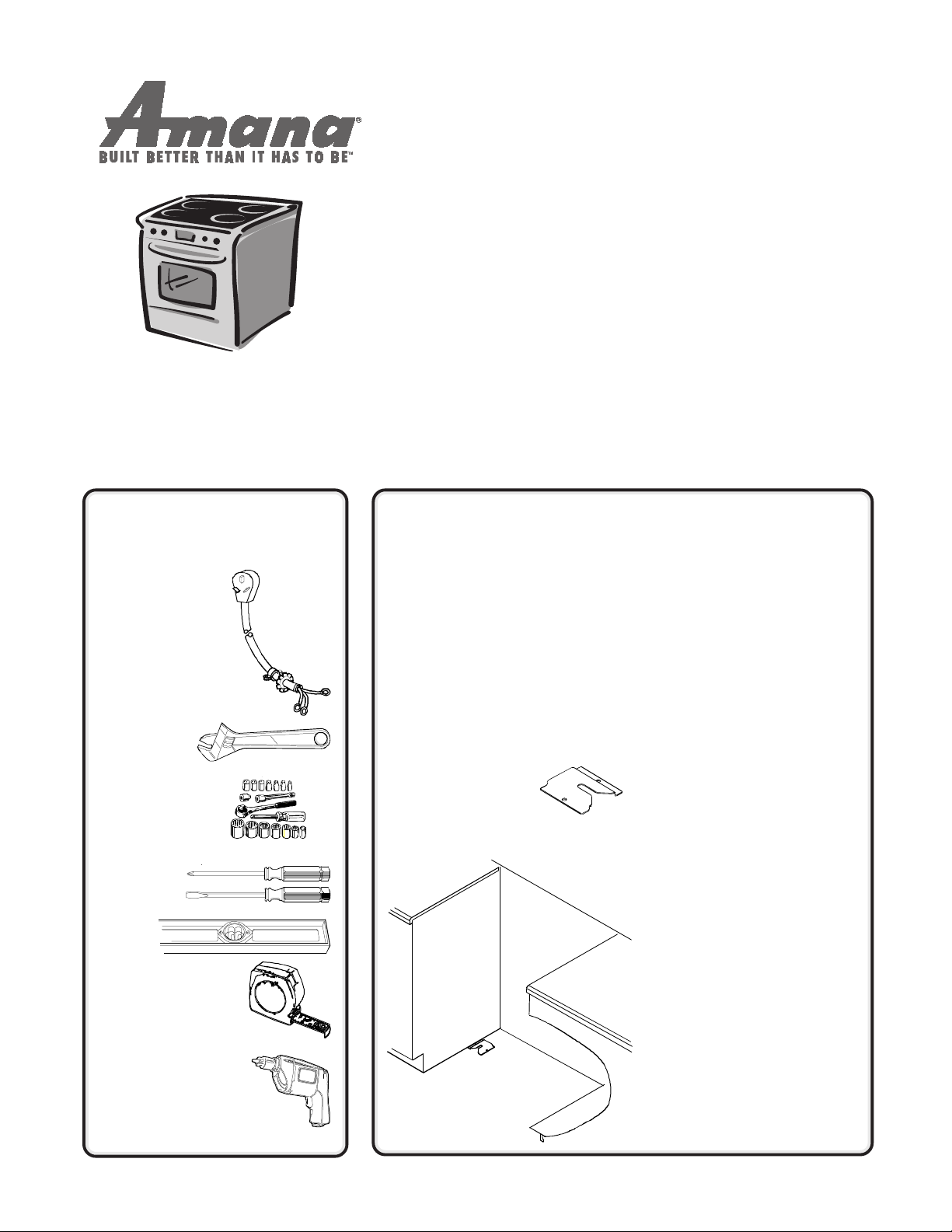
You'll Need a Few
Things Before You Begin
Power Cord
(3-wire or 4-wire)
and Strain Relief
Wrench
3
/8" Nut Driver
or Sockets
Screw
Drivers
Level
Tape Measure
Drill and DrillBit
3
/32" for wood floor
3
/16" for concrete floor
PREPARE TO
INSTALL RANGE
1
AND INSTALL
ANTI-TIP
BRACKET
Measure cabinet area and prepare
it according to illustrations in
Minimum Clearances to
Combustible Surfaces
and Cabinet Dimensions
this manual.
Remove the packing
materials and locate
the anti-tip bracket,
screws and plastic
anchors.
Anti-tip
bracket can
be installed
on either
side of
range.
and
Range
section in
Anti-tip Bracket Installation
T o avoid risk of range tipping, secure
range with a properly installed antitip bracket.
1. Remove storage drawer.
2. Unscrew rear leveling legs so
they extend at least ¼ inch to
engage bracket.
3. Move range to where it will be
installed.
4. Position anti-tip bracket. With
range in position, reach through
storage drawer opening and
slide anti-tip bracket on either
left or right rear leveling leg.
Slide leg into V-shaped notch in
bracket.
5. Mark location of side and front
of anti-tip bracket on floor.
6. Remove anti-tip bracket and
range from opening.
7. Position anti-tip bracket
according to lines marked on
floor, mark 2 hole locations in
anti-tip bracket, remove bracket
and drill 2 holes.
• If drilling into wood, use a
3
/32" drill bit. If drilling into
concrete or tile, use a
masonry drill bit and insert
plastic anchors.
8. Secure bracket to floor using
screws supplied.
3
/16"
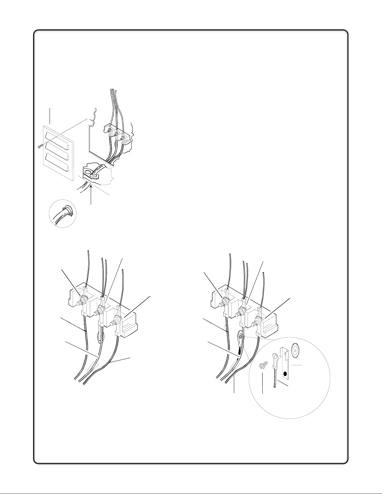
CONNECT
ELECTRICAL
2
CORD
To place electrical receptacle, see
Electrical Receptacle Location
diagram in this manual.
Access
cover
Strain relief
(not supplied with range)
3-wire or 4-wire Plug Connection
Four-wire cord is required for mobile homes or where codes do not permit
grounding through neutral.
1. Remove access cover from rear of range.
2. Use a strain relief (not supplied) and insert end of power cord (not
supplied) through power supply hole.
3. 4-wire Plug Only—Remove the green ground screw from range ground
strap. Remove both the hex nuts and the grounding strap from the center
terminal. Position grounding strap down and away from terminal block.
Replace 1 hex nut on the center terminal. Attach the power cord ground
wire (green or bare) and grounding strap to rear bulkhead using green
ground screw.
4. Unscrew and use top hex nut to attach the power cord wires to the
terminal block as follows:
• Red wire to “L1” terminal.
• Black wire to “L2” terminal.
• White wire to Neutral terminal.
5. T ighten all hex nuts and reinstall access cover removed in step 1.
4-wire Cord Installed3-wire Cord Installed
Neutral
"L1"
"L2"
Red
White
Black
Converting 3-Wire to 4-Wire Power Cord
1. Remove access cover from rear of range.
2. Remove bottom strain relief screw and retain for further use.
3. Remove hex nuts from terminal block and retain for further use.
4. Remove all 3-wire cable leads from the terminal block and proceed to
remove the power cord from the range by pulling in a downward motion
so the cord is removed from strain relief.
5. To install the 4-wire cord, follow the 4-wire instructions
"L1"
Red
White
shown above.
Black
Neutral
Ground
screw
"L2"
Ground
strap
Ground
wire
 Loading...