

Page 1
Portable
Instant Mount
Room Air Conditioners
Instructions
Read this entire installation manual thoroughly before beginning the installation. Make sure you have the necessary
tools and other materials for the job. Study the illustrations
in these instructions to become familiar with important
details of the installation process.
Read the Use & Care Manual to become familiar with the
operation of your room air conditioner.
Note:
1. Mechanical experience is required in order to install the air conditioner.
2. Installation can take from one (1) to three (3) hours,
depending upon the installer’s knowledge and skill.
3. If you are unable to solve a problem during installation, contact an authorized Amana servicer. The
contact and service are at the owner’s expense. If
you do not know who your local servicer is, call
Amana’s consumer information line toll free at 1800-843-0304, Monday through Friday.
Table of Contents
Introduction .......................................................... 1
Safety Instructions ............................................... 2
Installation Instructions ...................................... 2
Step 1 - Lay Out Kit Parts ............................................. 2
Step 2 - Prepare Window for Installation ....................... 3
Step 3 - Apply Window Sill Gasket ............................... 4
Step 4 - Install Support Bracket in Window ................... 5
Step 5 - Placing Unit in Window .................................... 5
Step 6 - Install Sash Bracket ........................................ 6
Step 7 - Secure Side Curtains ...................................... 6
Step 8 - Install Bottom Rail Screw ................................ 6
Step 9 - Install Window Seal Strip ................................. 7
Step 10 - Recheck Installation ...................................... 7
Removal Instructions .......................................... 8
Introduction
These instructions are provided for a standard double hung
window or mobile home double hung window installation in
windows 22-1/2” to 40” wide. Select a centrally located
window on the side of the room that receives the least direct
sunlight. There should be no obstruction to air flow either
inside (i.e. curtains) or outside (i.e. fence, wall or bushes).
Important: It is important, both for your personal
safety and to avoid possible damage to your appliance
or your home, that you observe the safety instructions
that are given following this symbol.
RECOGNIZE THIS SYMBOL
AS A SAFETY PRECAUTION
After installing the unit, reread these instructions to ensure
you have completed each step and all parts are fastened in
place for a secure installation.
For best results, perform all the installation procedure in the
order given. Doing so will minimize the time required to
install the unit.
October 1997(1)
Page 2
BASIC TOOLS NEEDED:
Installation Hardware
WARNING
•Tight Fitting gloves
•Standard screwdriver
•Phillips screwdriver
•Pliers
•Sharp knife
•Carpenters level
•1/4” hex driver
•Tape measure
•Electric drill
•1/8” drill bit
Safety Instructions
The receptacle should be an individual branch circuit used
only for this air conditioner. Be sure the electrical service is
adequate for the model air conditioner you’ve chosen. The
complete electrical rating of your air conditioner is stated on
the serial plate located behind the front grille. Be sure the
plug receptacle is close enough for the power cord to reach
it.
To avoid death, personal injury or property
damage due to electrical shock, this unit
must be grounded. Do not under any
circumstances cut or remove the round
grounding prong from the plug. Do not use
a two-prong adapter.
WARNING
To avoid death, personal injury or property
damage due to electrical shock, do not use
an extension cord. Do not pinch the power
cord. Do not remove the warning tag from
the power cord.
To minimize shock and fire hazards, proper grounding is
important. For your safety and protection, this air conditioner is equipped with a special three-prong grounding plug
on the service cord.
Your air conditioner must be plugged into a properly
grounded and polarized three-prong receptacle. Do not use
an adapter plug. If the wall receptacle you intend to use will
not accept a three-prong plug, or if you are not sure the outlet
is adequately grounded or protected by a time delay fuse or
circuit breaker, have a qualified electrician install the proper
outlet according to the National Electric Code and applicable
local code.
Installation Instructions
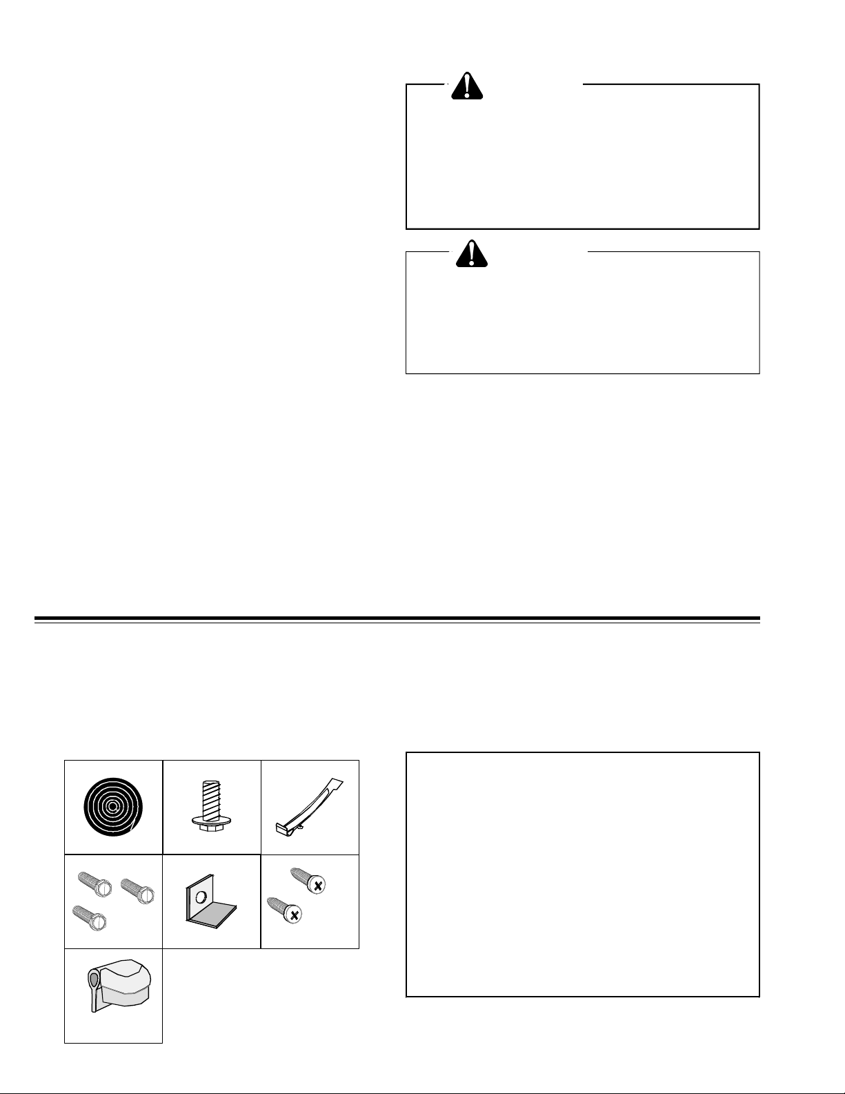
Step 1 - Lay Out Kit Parts
Lay out kit parts. They are numbered in the order in which
you use them (Figure 1).
12
4
7
5
Figure 1
3
6
Item # Description Qty.
1. Window Sill Gasket (1/2" x 1/4") 40"
2. 1-1/4" Long Adjusting Foot 1
3. Support Bracket 1
4. 7/8" Long Hex head Screws 3
5. Sash Bracket 1
6. 5/8" Long Phillips Screws 2
7. Window Seal Strip (3/4" x 1 1/2") 40"
Table 1
2
Page 3
Step 2 - Prepare Window for Installation
WARNING
To reduce the risk of electric shock, personal
injury or death, turn the fan control to the off
position and unplug the unit from the wall
outlet before installing or removing this
unit.
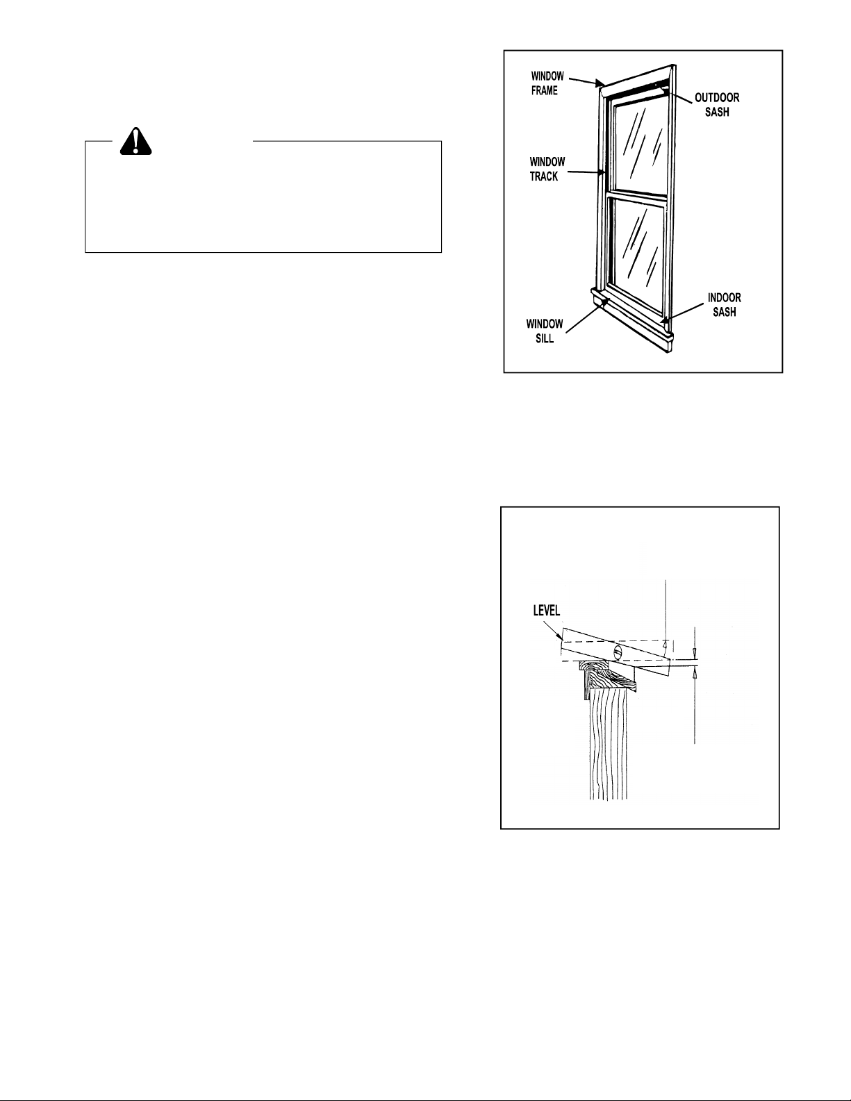
Inspect window track, sash, and sill to be sure they are
strong enough to hold an air conditioner (Figure 2). Measure width opening to be sure instant mount will fit in the
window. Instant mount models are designed for windows
22-1/2” to 40” wide.
The Instant Mount kit supplied with your unit is designed for
mounting in most double hung windows that do not have
storm windows installed. If your window has a storm window
installed, the window sill may have to be modified to accommodate this unit. This involves adding wood strips to the
inner and outer sills which raise the unit high enough to
eliminate interference with the storm window frame.
For storm window installation:
Determine if an interference exists between the storm
window frame and the unit support bracket by doing the
following:
(1) Place a carpenter’s level across from the window sill to
the storm window frame (Figure 3). If the level slopes
towards the outdoor side, (2) raise the outdoor end of the
level until the bubble is centered in the glass. (3) Measure
the distance from the bottom of the level to the top of the
storm window frame. If this measurement is one inch or
more, no interference problem should exist.
If the distance is less than one inch, subtract the measurement from one inch. For example, if your measurement is
1/4”, 1” minus 1/4” equals 3/4”. This is the minimum total
thickness of wood strip needed to eliminate support bracket
interference with the storm window frame. You may use a
thicker wood strip (i.e. 1”) if it is more convenient.
1. LEVEL SLOPES
TOWARD OUTOORS
Figure 2
2. RAISE OUTDOOR END
UNTIL BUBBLE CENTERS
3. SUBTRACT THIS
DISTANCE FROM 1” TO
DETERMINE WOOD STRIP
THICKNESS
Figure 3
3
Page 4

(1) If the level slopes towards the indoor side, (2) raise the
indoor end of the level until the bubble is centered in the glass
(Figure 4). (3) Measure the distance from the bottom of the
level to the top of the window sill. Add one inch to this number.
For example, if your measurement is 3/8”, 1” plus 3/8” equals
1 3/8”. This is the total minimum thickness of the wood strip
needed to eliminate support bracket interference with the
storm window frame. You may use a thicker wood strip (i.e.
1 1/2”) if it is more convenient.
Install the wood strip to the window sill across the complete
width of the window frame and even with the back edge of
the window sill using at least three screws. This wood strip
should be the thickness calculated above. (See Figure 5.)
Next secure a wood block approximately six inches long, 4
1/4” wide and the same thickness as the first strip with at
least three screws in the center of the window sill. This will
raise the support bracket described in Step 4.
Figure 4
Step 3 - Apply Window Sill Gasket
Measure the width of the window sash, including the
portion inside the window track. Cut the window sill
gasket (Item 1) to this length and apply to backside of
window sill or wood strip installed in Step 2 above (Figure
6).
Figure 5
Figure 6
4
Page 5

Step 4 - Install Support Bracket in Window
Thread the adjusting screw (Item 2) through the bottom of
the support bracket (Item 3). Measure the window to determine the center of the sill. Use two of the hex head screws
(Item 4) supplied in the kit to install the bracket in the center
of the sill 1 3/16” from the back of the sill (Figure 7).
Place the carpenter’s level on the sill and the outdoor end of
the support. Turn the adjustment screw until the level is
tilted 1/4 bubble toward the outdoor side.
Step 5 - Placing Unit in Window
CAUTION
!
Figure 7
When installing, hold unit firmly until
window sash is lowered to top channel
behind top rail. Otherwise, personal injury
or property damage may result if unit falls
from window.
CAUTION
!
Unit is heavy. To avoid injury or accident, it
is strongly recommended that you have
additional help when lifting the unit.
Open window and place the unit in the center of the window
frame. The bottom rail of the Instant Mount should fit behind
the sill and in front of the support bracket. Pull down the
window sash on top of the unit, behind the top rail of the
Instant Mount. The window sash helps hold the unit in the
window. It must be down at all times (Figure 8).
The unit should be installed with at least 1/4” slope to the
outside for proper condensate drainage. This is about equal
to 1/4 to 1/2 bubble on your level. If necessary, remove the
unit from the window and use support bracket adjusting
screw to obtain the proper slope (Figure 9).
Figure 8
Figure 9
5
Page 6

Step 6 - Install Sash Bracket
CAUTION
!
To prevent damage to any locking or lifting
mechanism located in the window frame,
inspect frame before drilling or installing
screws.
Install sash bracket (Item 5) with the remaining hex head
screw (Item 4) to top of indoor window sash as shown in
Figure 10 or directly into side of window frame. This will
prevent raising of the window from the outside. If you have
a hard wood or metal window frame, a 1/8” pilot hole may be
needed in order to drive the screw.
Step 7 - Secure Side Curtains
CAUTION
!
To prevent damage to any locking or lifting
mechanism located in the window frame,
inspect frame before drilling or installing
screws.
Figure 10
To provide a proper seal, pull each expandable side curtain
out and up until it is tight against the window frame. Using
the hole in the top of each curtain as a guide, mark the hole
location and drill a 1/8” pilot hole into the window sash.
Secure each curtain to the sash using the Phillips head
screws (Item 6) (Figure 11).
If you do not want to make holes in your window sash, you
may try to let the downward force of the window, hold the
curtains in place. If the curtains do not stay in place, the air
seal will not be good and your electricity usage will rise.
Step 8 - Install Bottom Rail Screw
Remove front insert grille and air filter (see Use and Care
Manual, Air Filter). Remove the four screws holding the
interior front in place (Figure12). Using pliers or screwdriver
bend tab with hole down towards window sill (Figure 13).
Secure tab to sill with 5/8” long Phillips head screw (Item
6)(Figure 13).
Figure 11
INTERIOR FRONT
Figure 12
6
Page 7

Figure 13
Replace interior front, air filter and front insert grille.
Step 9 - Install Window Seal Strip
CAUTION
!
It is important to install the bend tab screw.
Failure to do so may result in damage to
your unit if the sash is raised accidentally.
Cut the window seal strip (Item 7) to the width of the
windows. Stuff window seal strip between outdoor window
glass and the top of the indoor sash for a tight seal (Figure
14). This provides a seal against hot outside air as well as
preventing insects from entering.
Step 10 - Recheck Installation
To be sure you have correctly installed your Amana Room
Air Conditioner, review the steps and make sure all of the
parts are securely fastened in the window as the instructions
show. A tight seal is essential.
Settling of your home may cause warping or bowing of
windows. To ensure a tight seal, use a suitable plastic sealer
available at hardware stores as needed to plug any holes or
cracks. Plug unit into electrical outlet recommended in the
Use & Care Manual to begin operation.
Read through the Use & Care Manual to become familiar
with the operation of your room air conditioner.
Figure 14
7
Page 8

Removal Instructions
CAUTION
!
The unit is heavy. To avoid injury or
accident, it is strongly recommended that
you have additional help when lifting the
unit. Do not lift window sash without
holding the unit. The window sash helps to
keep the unit in the window. Exercise
caution when opening the window. Failure
to do so may result in personal injury and/
or property damage.
Remove the window seal strip and the sash bracket screw.
Remove the small wood screws from the side curtains. Fold
the curtains back toward the unit and carefully raise the
window sash. Remember, the window sash helps hold the
unit in the window frame, so exercise caution when opening
the window. Lift unit out of the window. Remove support
bracket, if desired.
NOTE: Abide by state and local codes when disposing of an
air conditioning unit.
Part No. 20058201
Printed in U.S.A.
CONSUMER INFORMATION LINE
TOLL FREE 1-800-843-0304
(Monday through Friday)
©1997 Amana
2800 220th Trail
Amana, Iowa 52204
8
 Loading...