

Page 1

INSTALLATION INSTRUCTIONS
IMPORTANT:
.
30" (76 CM) FREESTANDING ELECTRIC RANGES
Table of Contents
RANGE SAFETY .............................................................................2
INSTALLATION REQUIREMENTS .................................................3
Tools and Parts .............................................................................3
Location Requirements ................................................................4
Electrical Requirements ...............................................................5
INSTALLATION INSTRUCTIONS ...................................................6
Unpack Range..............................................................................6
Install Anti-Tip Bracket .................................................................6
Electrical Connection ...................................................................8
Verify Anti-Tip Bracket Is Installed and Engaged ......................11
Level Range ................................................................................11
Storage Drawer ..........................................................................11
Oven Door ..................................................................................11
Complete Installation .................................................................12
Moving the Range ......................................................................12
Save for local electrical inspector's use
W11034224A
Page 2
RANGE SAFETY
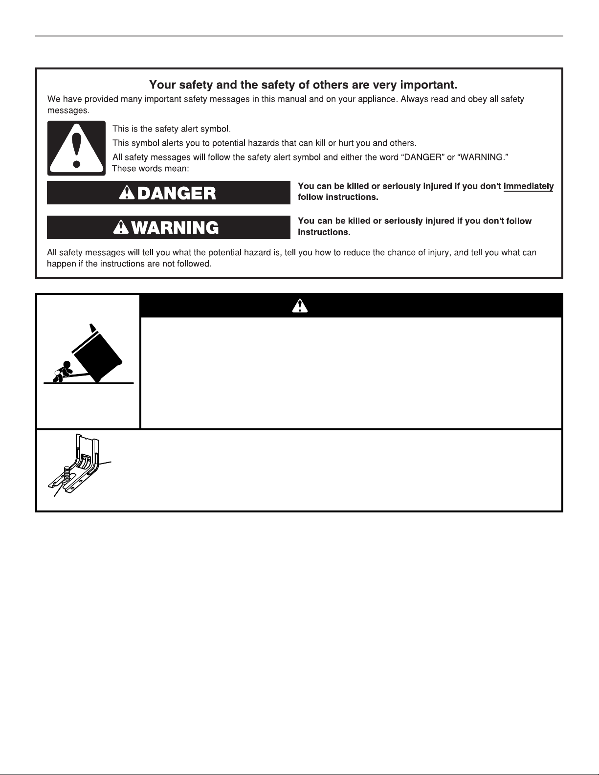
WARNING
Tip Over Hazard
A child or adult can tip the range and be killed.
Install anti-tip bracket to floor or wall per installation instructions.
Slide range back so rear range foot is engaged in the slot of the anti-tip bracket.
Re-engage anti-tip bracket if range is moved.
Do not operate range without anti-tip bracket installed and engaged.
Failure to follow these instructions can result in death or serious burns to children and adults.
Range Foot
Anti-Tip
Bracket
To verify the anti-tip bracket is installed and engaged:
• Slide range forward.
• Look for the anti-tip bracket securely attached to floor or wall.
• Slide range back so rear range foot is under anti-tip bracket.
• See installation instructions for details.
2
Page 3
INSTALLATION REQUIREMENTS
A
B
Tools and Parts
Gather the required tools and parts before starting installation.
Read and follow the instructions provided with any tools
listed here.
Tools needed
■ Tape measure
■ Flat-blade screwdriver
■ Phillips screwdriver
■ Level
■ Hammer
■ Hand or electric drill
■ Wrench or pliers
■ Marker or pencil
Parts supplied
Check that all parts are included.
■ 10-32 hex nuts (attached to terminal block) (3)
■ Terminal lugs (3)
■ Masking tape
1
■
/4" drive ratchet
1
■
/4" nut driver
3
■
/8" and 5/16" nut driver
1
■
/8" (3.2 mm) drill bit (for
wood floors)
■ Tin snips or large wire
cutters (for cutting ground
strap if necessary)
■ Polychloroprene sheathed
Their properties shall be at least those of ordinary
polychloroprene sheathed cords (code designation
60245 IEC 57).
NOTE 2: These cords are suitable for appliances
intended to be used in low temperature applications.
■ Polyvinyl chloride sheathed
These cords shall not be used if they are likely to touch
metal parts having a temperature rise exceeding 75 K.
Their properties shall be at least those of
■ light polyvinyl chloride sheathed cord (code
designation 60227 IEC 52), for appliances having a
mass not exceeding 3 kg;
■ ordinary polyvinyl chloride sheathed cord (code
designation 60227 IEC 53), for other appliances.
■ Heat resistant polyvinyl chloride sheathed
These cords shall not be used for type X attachment
other than specially prepared cords
Their properties shall be at least those of
■ heat-resistant light polyvinyl chloride sheathed cord
(code designation 60227 IEC 56), for appliances
having a mass not exceeding 3 kg;
■ heat-resistant polyvinyl chloride sheathed cord (code
designation 60227 IEC 57), for other appliances.
■ Halogen-free, low smoke, thermoplastic insulated and
sheathed
Their properties should be at least those of
■ light duty halogen-free low smoke flexible cable
(code designation 62821 IEC 101 for circular cable
and code designation 62821 IEC 101f for flat cable);
■ ordinary duty halogen-free, low smoke flexible cable
(code designation 62821 IEC 102 for circular cable
and code designation 62821 IEC 102f for flat cable).
■ For appliances with supply cords, the arrangement of
the terminals, or the length of the conductors between
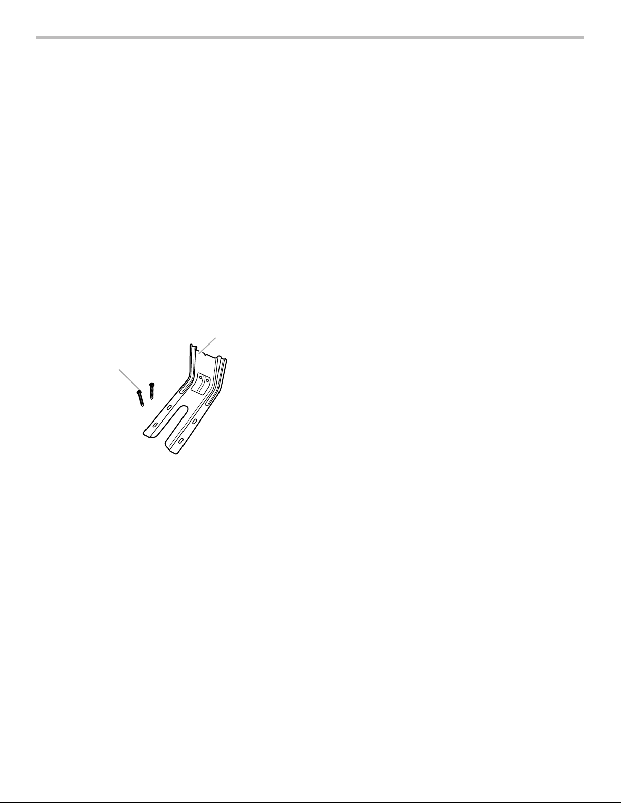
A. Anti-tip bracket
B. #12 x 1
■ Anti-tip bracket must be securely mounted to floor or wall.
5
/8" screws (2)
Thickness of flooring may require longer screws to anchor
bracket to floor.
Parts needed
If using a power supply cord kit:
■ A certified 60245 or 60227 IEC 53 (minimum) supply cord
set marked for use with ranges. The cord should be rated
300/300V minimum, 6 mm2 for 220V or 10 mm2 for 230V,
that is marked for use with nominal 13/8" (3.5 cm) diameter
connection opening and must end in ring terminals or
Check local codes. Check existing electrical supply. See the
“Electrical Requirements” section.
It is recommended that ALL electrical connections be made by a
licensed, qualified electrical installer.
the cord anchorage and the terminals, shall be such
that the current carrying conductors become taut before
the earthing conductor if the cord slips out of the cord
anchorage.
■ An IEC certified cord anchorage, which is suitable for
use with the particular supply cord jacket material,
sized for 6 mm2 for 220V cords or 10 mm2 for
230V cords; and installed in accordance with the
manufacturers’ installation instructions.
open-end spade terminals with upturned ends. The earthing
conductor must be longer than the other conductors present.
■ Supply cords for appliances other than class III appliances
shall be one of the following types:
■ Rubber sheathed
Their properties shall be at least those of ordinary tough
rubber sheathed cords (code designation 60245 IEC 53).
NOTE 1: These cords are not suitable for appliances
intended to be used outdoors or when they are liable to
be exposed to significant amounts of ultraviolet radiation.
3
Page 4
If connecting to a 3-wire system:
■ A certified 60245 or 60227 IEC 53 (minimum) supply cord
set marked for use with ranges. The cord should be rated
300/300V minimum, 6 mm2 for 220V or 10 mm2 for 230V, that
is marked for use with nominal 3.5 cm diameter connection
opening and must end in ring terminals or open-end spade
terminals with upturned ends, terminating in an IEC 60309
plug on the supply end. Connectors on the appliance end
must be provided at the point the power supply cord enters
the appliance. This uses a 3 wire receptacle of IEC 60309.
The earthing conductor must be longer than the other
conductors present.
■ Supply cords for appliances other than class III appliances
shall be one of the following types:
■ Rubber sheathed
Their properties shall be at least those of ordinary tough
rubber sheathed cords (code designation 60245 IEC 53)
NOTE 1: These cords are not suitable for appliances
intended to be used outdoors or when they are liable to
be exposed to significant amounts of ultraviolet radiation.
■ Polychloroprene sheathed
Their properties shall be at least those of ordinary
polychloroprene sheathed cords (code designation
60245 IEC 57)
NOTE 2: These cords are suitable for appliances
intended to be used in low temperature applications.
■ Polyvinyl chloride sheathed
These cords shall not be used if they are likely to touch
metal parts having a temperature rise exceeding 75 K.
Their properties shall be at least those of
■ light polyvinyl chloride sheathed cord (code
designation 60227 IEC 52), for appliances having a
mass not exceeding 3 kg;
■ ordinary polyvinyl chloride sheathed cord (code
designation 60227 IEC 53), for other appliances.
■ Heat resistant polyvinyl chloride sheathed
These cords shall not be used for type X attachment
other than specially prepared cords
Their properties shall be at least those of
■ heat-resistant light polyvinyl chloride sheathed cord
(code designation 60227 IEC 56), for appliances
having a mass not exceeding 3 kg;
■ heat-resistant polyvinyl chloride sheathed cord (code
designation 60227 IEC 57), for other appliances.
■ Halogen-free, low smoke, thermoplastic insulated and
sheathed
Their properties should be at least those of
■ light duty halogen-free low smoke flexible cable
(code designation 62821 IEC 101 for circular cable
and code designation 62821 IEC 101f for flat cable);
■ ordinary duty halogen-free, low smoke flexible cable
(code designation 62821 IEC 102 for circular cable
and code designation 62821 IEC 102f for flat cable).
■ For appliances with supply cords, the arrangement of
the terminals, or the length of the conductors between
the cord anchorage and the terminals, shall be such
that the current carrying conductors become taut before
the earthing conductor if the cord slips out of the cord
anchorage.
■ An IEC certified cord anchorage, which is suitable for
use with the particular supply cord jacket material,
sized for 6 mm2 for 220V cords or 10 mm2 for
230V cords; and installed in accordance with the
manufacturers’ installation instructions.
Check local codes. Check existing electrical supply. See the
“Electrical Requirements” section.
It is recommended that ALL electrical connections be made by a
licensed, qualified electrical installer.
Location Requirements
IMPORTANT: Observe all governing codes and ordinances.
■ It is the installer’s responsibility to comply with installation
clearances specified on the model/serial/rating plate. The
model/serial/rating plate is located on the frame behind a
top corner of the door or either side of the drawer.
■ Cabinet opening dimensions that are shown must be used.
Given dimensions are minimum clearances.
■ The anti-tip bracket must be installed. To install the anti-tip
bracket shipped with the range, see the “Install Anti-Tip
Bracket” section.
■ Grounded electrical supply is required. See the appropriate
“Electrical Requirements” section.
IMPORTANT: To avoid damage to your cabinets, check with
your builder or cabinet supplier to make sure that the materials
used will not discolor, delaminate or sustain other damage. This
oven has been designed in accordance with the requirements of
the IEC and complies with the maximum allowable wood cabinet
temperatures of 194°F (90°C).
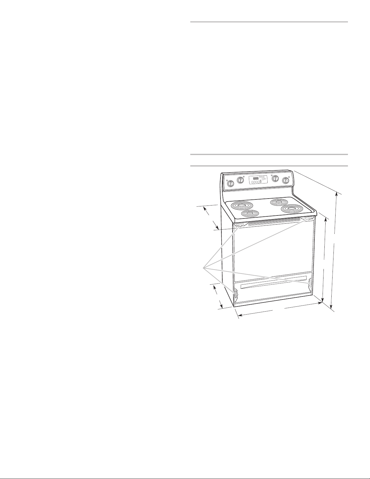
Product Dimensions
A
B
F
E
D
A. 273/4" (70.5 cm) max. depth with handle
7
B. 46
/8" (119.1 cm) overall height (max.) with leveling legs
screwed all the way in*
C. 36" (91.4 cm) cooktop height (max.) with leveling legs
screwed all the way in*
7
D. 29
/8" (75.9 cm) width
5
E. 25
/16" (64.3 cm) depth - back of range to front of cooktop**
F. Model/serial/rating plate (located on the frame behind a top
corner of the door or either side of the drawer)
NOTE: This manual covers several models. Details of your
range may differ from the range graphic shown above.
IMPORTANT: Range must be level after installation. Follow the
instructions in the “Level Range” section. Using the cooktop as
a reference for leveling the range is not recommended.
* Range can be raised approximately 1" (2.5 cm) by adjusting
the leveling legs.
** Front of door and drawer may extend further forward
depending on styling.
C
4
Page 5

Cabinet Dimensions
Cabinet opening dimensions shown are for 25" (64.0 cm)
countertop depth, 24" (61.0 cm) base cabinet depth and
36" (91.4 cm) countertop height.
IMPORTANT: If installing a range hood or microwave hood
combination above the range, follow the range hood or
microwave hood combination installation instructions for
dimensional clearances above the cooktop surface.
A freestanding range may be installed next to combustible
walls with zero clearance.
A
B
D
E
C
Electrical Requirements
If codes permit and a separate ground wire is used, it is
recommended that a qualified electrical installer determine that
the ground path and wire gauge are in accordance with local
codes.
Do not use an extension cord.
Be sure that the electrical connection and wire size are adequate
and in conformance with all local codes and ordinances.
WARNING: Improper connection of the equipment-grounding
conductor can result in a risk of electric shock. Check with a
qualified electrician or service technician if you are in doubt as to
whether the appliance is properly grounded. Do not modify the
power supply cord plug. If it will not fit the outlet, have a proper
outlet installed by a qualified electrician.
Electrical Connection
To properly install your range, you must determine the type of
electrical connection you will be using and follow the instructions
provided for it here.
■ Range must be connected to the proper electrical voltage
and frequency as specified on the model/serial/rating plate.
The model/serial/rating plate is located on the frame behind
a top corner of the door or either side of the drawer. Refer
to the figures in “Product Dimensions” in the “Location
Requirements” section.
F
A. 13" (33.0 cm) max. upper cabinet depth
B. 30" (76.2 cm) min. opening width
C. For minimum clearance to top of cooktop, see NOTE*
1
D. 30
/8" (76.5 cm) min. opening width
E. Outlet - 8" (20.3 cm) to 22" (55.9 cm) from either
cabinet, 5
7
F.
/8" (2.2 cm) min. required between cutout and
cabinet door or hinge.
1
/2" (14.0 cm) max. from floor
* NOTE: 24" (61.0 cm) minimum when bottom of wood or
metal cabinet is covered by not less than 1/4" (0.64 cm) flame
retardant millboard covered with not less than No. 28 MSG
sheet steel, 0.015" (0.4 mm) stainless steel, 0.024" (0.6 mm)
aluminum or 0.020" (0.5 mm) copper.
30" (76.2 cm) minimum clearance between the top of the
cooking platform and the bottom of an uncovered wood or
metal cabinet.
Range Rating
Power Supply Cord Kit
and Circuit Protection
220 Volts 230 Volts Amps
7.4 - 13.8 KW 8.1 - 15.1 KW 40 or 50*
13.9 - 18.9 KW 15.1 - 20.6 KW 50
* If connecting to a 50-amp circuit, use a 50-amp rated cord
with kit. For 50-amp rated cord kits, use kits that specify use
with a nominal 13/8" (34.9 mm) diameter connection opening.
Specified Rating of
■ A circuit breaker is recommended.
■ The range can be connected directly to the circuit breaker
box (or fused disconnect) through flexible or nonmetallic
sheathed, copper or aluminum cable. See the “Electrical
Connection” section.
■ Allow 2 to 3 ft (61.0 cm to 91.4 cm) of slack in the line so that
the range can be moved if servicing is ever necessary.
■ An IEC Approved conduit connector must be provided at
each end of the power supply cable (at the range and at the
junction box).
■ Wire sizes and connections must conform with the rating of
the range.
■ The wiring diagram is located on the Tech Sheet.
■ The Tech Sheet is located on the back of the range inside a
clear plastic bag.
5
Page 6

INSTALLATION INSTRUCTIONS
A
A
B
B
Unpack Range
WARNING
Excessive Weight Hazard
Use two or more people to move and install range.
Failure to do so can result in back or other injury.
1. Remove shipping materials, tape, and film from range.
2. Remove oven racks and parts package from inside oven.
3. Do not remove the shipping base at this time.
A. Shipping base
On Ranges Equipped with a Storage Drawer:
Remove the storage drawer. See the “Storage Drawer”
section. Use a 1/4" drive ratchet to lower the rear leveling legs
one-half turn. Use a wrench or pliers to lower front leveling
legs one-half turn.
D
C
Install Anti-Tip Bracket
WARNING
Tip Over Hazard
A child or adult can tip the range and be killed.
Install anti-tip bracket to floor or wall per installation
instructions.
Slide range back so rear range foot is engaged in the
slot of the anti-tip bracket.
Re-engage anti-tip bracket if range is moved.
Do not operate range without anti-tip bracket installed
and engaged.
Failure to follow these instructions can result in death
or serious burns to children and adults.
1. Remove the anti-tip bracket from where it is taped inside the
storage drawer.
2. Determine which mounting method to use: floor or wall.
If you have a stone or masonry floor, you can use the wall
mounting method. If you are installing the range in a mobile
home, you must secure the range to the floor.
3. Determine and mark centerline of the cutout space. The
mounting can be installed on either the left side or right side
of the cutout. Position mounting bracket against the wall in
the cutout so that the V-notch of the bracket is 129/16"
(31.9 cm) from centerline as shown.
A. 1/4" drive ratchet
B. Rear leveling leg
C. Wrench or pliers
D. Front leveling leg
6
Centerline
A
A. 129/16" (31.9 cm)
B. Bracket V-notch
Page 7

4. Drill two 1/8" (3 mm) holes that correspond to the bracket
holes of the determined mounting method. See the following
illustrations.
Floor Mounting
5. Using the Phillips screwdriver, mount anti-tip bracket to the
wall or floor with the two #12 x 15/8" screws provided.
6. Move range close enough to opening to allow for final
electrical connections. Remove shipping base, cardboard, or
hardboard from under range.
7. Move range into its final location, making sure rear leveling
leg slides into anti-tip bracket.
Rear position Front position Diagonal (2 options)
Wall Mounting
8. Move range forward onto shipping base, cardboard, or
hardboard to continue installing the range using the following
installation instructions.
7
Page 8

Electrical Connection
B
C
Power Supply Cord Direct Wire
WARNING
Electrical Shock Hazard
Disconnect power before servicing.
Use a new 40 amp power supply cord.
Plug into a grounded outlet.
Failure to follow these instructions can result in death,
fire, or electrical shock.
1. Disconnect power.
2. Remove the terminal block cover screws located on the back
of the range. Pull cover down and toward you to remove
cover from range.
A
WARNING
Electrical Shock Hazard
Disconnect power before servicing.
Use 8 gauge copper or 6 gauge aluminum wire.
Electrically ground range.
Failure to follow these instructions can result in death,
fire, or electrical shock.
4. Add strain relief.
Style 1: Power supply cord strain relief
■ Remove the knockout for the power supply cord.
■ Assemble a IEC Approved strain relief in the opening.
A. 2 mounting tabs each side
B. Terminal block cover
C. Hex-head screws
3. Remove plastic tag holding three 10-32 hex nuts from the
middle post of the terminal block.
8
A
A. IEC Approved strain relief
■ Tighten strain relief screw against the power supply cord.
Page 9

Style 2: Direct wire strain relief
(7.6 cm)
"
A
D
C
E
D
■ Remove the knockout as needed for the flexible conduit
connection.
■ Assemble an IEC Approved conduit connector in the
opening.
A
B
A. Removable retaining nut
B. Conduit
■ Tighten strain relief screw against the flexible conduit.
5. Complete installation following instructions for your type of
electrical connection:
3-wire
Electrical Connection Options
2. Feed the power supply cord through the strain relief on the
cord/conduit plate on bottom of range. Allow enough slack
to easily attach the wiring to the terminal block.
B
C
A. Terminal block
B. Location of ground-link screw
C. IEC Approved strain relief
D. Power supply cord wires - large opening
3. Use a Phillips screwdriver to connect the ground (green/
yellow) wire from the power supply cord to the range with the
ground-link screw and ground-link section. The ground wire
must be attached first.
4. Use 3/8" nut driver to connect the neutral (red) wire to the left
terminal block post with 1 of the 10-32 hex nuts.
If your home has:
3-wire receptacle An IEC 60309
And you will be
connecting to:
listed, 250-volt
minimum, 40-amp
Go to Section:
3-wire connection:
Power Supply Cord
A
minimum, range
power supply cord
3-wire direct A circuit breaker
³⁄₈
(1.0 cm)
3"
3-wire connection: Power Supply Cord
box or fused
disconnect
Use this method only if local codes permit connecting chassis
ground conductor to neutral wire of power supply cord.
1. Use a Phillips screwdriver to remove the ground-link screw
from the back of the range. Save the ground-link screw.
3-wire connection:
Direct Wire
5. Connect the line 1 (black) wire to the right terminal block
post with 1 of the 10-32 hex nuts.
6. Securely tighten hex nuts.
NOTE: For power supply cord replacement, use only a
power cord rated at 250 volts minimum, 40 amps or 50 amps
B
A. 10-32 hex nut
B. Neutral (red) wire
C. Ground-link screw
D. Ground (green/yellow) wire
E. Line 1 (black) wire
that is marked for use with nominal 13/8" (3.5 cm) diameter
connection opening, with ring terminals and marked for use
with ranges.
7. Tighten strain relief screws.
8. Replace terminal block access cover.
9
Page 10

Direct Wire Installation: Copper or Aluminum Wire
(7.6 cm)
"
A
C
A
B
C
This range may be connected directly to the fuse disconnect or
circuit breaker box. Depending on your electrical supply, make
the required 3-wire connection.
NOTE: Connections to ground should not use aluminum wire.
1. Strip outer covering back 3" (7.6 cm) to expose wires. Strip
the insulation back 3/8" (1.0 cm) from the end of each wire.
³⁄₈
(1.0 cm)
2. Attach terminal lugs to neutral (red), bare (green/yellow)
ground, and line 1 (black) wires. Loosen (do not remove) the
setscrew on the front of the terminal lug and insert exposed
wire end through bottom of terminal lugs. Securely tighten
setscrew to torque as shown in the following Bare Wire
Torque Specifications chart.
3"
2. Allow enough slack in the wire to easily attach the wiring
terminal block.
3. Complete electrical connection according to your type of
electrical supply (3-wire connection).
3-wire connection: Direct Wire
Use this method only if local codes permit connecting ground
conductor to neutral supply wire.
1. Pull the wires through the conduit on cord/conduit plate on
bottom of range. Allow enough slack to easily attach the
wiring to the terminal block.
B
F
D
E
DE
A. Terminal lug
B. Setscrew
C. Neutral (red) wire
D. Bare (green/yellow) ground wire
E. Line 1 (black) wire
Bare Wire Torque Specifications
Attaching terminal lugs to the terminal block - 20 lbs-in.
(2.3 N-m)
Wire Awg Torque
8 gauge copper 25 lbs-in. (2.8 N-m)
6 gauge aluminum 35 lbs-in. (4.0 N-m)
3. Use 3/8" nut driver to connect the bare (green/yellow) ground
wire to the center terminal block post with 1 of the 10-32
hex nuts.
F
A
E
B
A. Terminal block
B. Ground-link screw
C. Cord/conduit plate
D. Neutral (red) wire
E. Bare (green/yellow) ground wire
F. Line 1 (black) wire
4. Connect neutral (red) and line 1 (black) wires to the outer
terminal block posts with 10-32 hex nuts.
A. 10-32 hex nut
B. Neutral (red) wire
C. Ground-link screw
D. Bare (green/yellow) ground wire
E. Line 1 (black) wire
F. Terminal lug
C
D
5. Securely tighten hex nuts.
6. Replace terminal block access cover.
10
Page 11

Verify Anti-Tip Bracket Is
A
Installed and Engaged
1. Remove the storage drawer. See the “Storage Drawer”
section.
2. Use a flashlight to look underneath the bottom of the range.
3. Visually check that the rear range foot is inserted into the
slot of the anti-tip bracket.
Level Range
1. Place a standard flat rack in oven.
2. Place level on the rack and check levelness of the range,
first side to side; then front to back.
3. If range is not level, pull range forward until rear leveling leg
is removed from the anti-tip bracket.
4. Use a 1/4" drive ratchet, wrench or pliers to adjust leveling
legs up or down until the range is level. Push range back
into position. Check that rear leveling leg is engaged in the
anti-tip bracket.
NOTE: Range must be level for satisfactory baking
performance.
Storage Drawer
The storage drawer can be removed. Before removing, make
sure drawer is cool and empty.
3. Slowly push the drawer into the range.
A. Engage drawer glide.
NOTE: When properly installed, the rear slides on the bottom
of the drawer will engage the base rails and the drawer will
not tip when items are placed in the drawer.
Oven Door
For normal range use, it is not suggested to remove the oven
door. However, if removal is necessary, make sure the oven is
off and cool. Then, follow these instructions. The oven door is
heavy.
To Remove:
1. Open oven door all the way.
2. Pinch the hinge latch between 2 fingers and pull forward.
Repeat on other side of oven door.
A
To Remove:
1. Pull the storage drawer straight back to the drawer stop.
A
A. Drawer stop notch
2. Lift up the front of the drawer and pull the drawer out.
To Replace:
1. Lift up the front of the drawer and place the rear of the
drawer inside the range so that the drawer stop notch is
behind the drawer glide.
2. Lower the drawer so that the edge of the slide rail drops into
the slot in the drawer glide.
A. Hinge latch
3. Close the oven door as far as it will shut.
4. Lift the oven door while holding both sides.
Continue to push the oven door closed and pull it away from
the oven door frame.
To Replace:
1. Insert both hanger arms into the door.
2. Open the oven door.
You should hear a “click” as the door is set into place.
3. Move the hinge levers back to the locked position. Check
that the door is free to open and close. If it is not, repeat the
removal and installation procedures.
11
Page 12

Complete Installation
WARNING
1. Check that all parts are now installed. If there is an extra
part, go back through the steps to see which step was
skipped.
2. Check that you have all of your tools.
3. Dispose of/recycle all packaging materials.
4. Check that the range is level. See the “Level Range” section.
5. Use a mild solution of liquid household cleaner and warm
water to remove waxy residue caused by shipping material.
Dry thoroughly with a soft cloth. For more information, read
the “Range Care” section of the Use and Care Guide.
6. Read the “Range Use” section in the range Use and
Care Guide.
7. Plug power cord into appropriate outlet. Turn power on.
8. Turn on surface burners and oven. See the Use and Care
Guide for specific instruction on range operation.
If range does not operate, check the following:
■ Household fuse is intact and tight or circuit breaker has
not tripped.
■ Range is plugged into a grounded outlet.
■ Electrical supply is connected.
■ See the “Troubleshooting” section in the Use and Care
Guide.
When the range has been on for 5 minutes, check for heat.
If range is cold, turn off the range and contact a qualified
technician.
Moving the Range
WARNING
If removing the range is necessary for cleaning or maintenance:
For power supply cord-connected ranges:
1. Slide range forward.
2. Unplug the power supply cord.
3. Complete cleaning or maintenance.
4. Plug in power supply cord.
5. Check that the anti-tip bracket is installed and engaged.
See the “Verify Anti-Tip Bracket Is Installed and Engaged”
section.
6. Check that range is level.
For direct-wired ranges:
Electrical Shock Hazard
Disconnect power before servicing.
Replace all parts and panels before operating.
Failure to do so can result in death or electrical shock.
1. Disconnect power.
2. Slide range forward.
3. Complete cleaning or maintenance.
4. Check that the anti-tip bracket is installed and engaged.
See the “Verify Anti-Tip Bracket Is Installed and Engaged”
section.
5. Check that range is level.
6. Reconnect power.
Tip Over Hazard
A child or adult can tip the range and be killed.
Install anti-tip bracket to floor or wall per installation
instructions.
Slide range back so rear range foot is engaged in the
slot of the anti-tip bracket.
Re-engage anti-tip bracket if range is moved.
Do not operate range without anti-tip bracket installed
and engaged.
Failure to follow these instructions can result in death
or serious burns to children and adults.
When moving range, slide range onto cardboard or hardboard to
avoid damaging the floor covering.
W11034224A ©2016. All rights reserved. 11/16
 Loading...