

Page 1
Instructions for Installing No. 402P3
!
!
Natural Gas Conversion Kit
WARNING
“This conversion kit shall be installed by a qualified service agency in accordance with the manufacturer’s
instructions and all applicable codes and requirements of the authority having jurisdiction. The information in these
instructions must be followed to minimize the risk of fire or explosion or to prevent property damage, personal
injury or death. The qualified service agency is responsible for the proper installation of this kit. The installation is
not proper and complete until the operation of the converted appliance is checked as specified in the
manufacturer’s instructions supplied with the kit.”
“THE CONVERSION SHALL BE CARRIED OUT IN ACCORDANCE WITH THE REQUIREMENTS OF THE
PROVINCIAL AUTHORITIES HAVING JURISDICTION AND IN ACCORDANCE WITH THE REQUIREMENTS OF
THE CAN-B149.1 AND CAN1-B149.2 INSTALLATION CODE.”
WARNING
To reduce the risk of electric shock, fire, explosion, serious injury or death:
• Disconnect electric power to the dr yer before ser vic in g.
• Close equipment shut-off valve to gas dryer before servicing.
• Never start the dryer with any guards/panels removed.
• Whenever ground wires are removed during servicing, these ground wires must be reconnected to ensure that
the dryer is properly grounded.
Important Note:
For proper operation at elevations above 2500 feet (760 m) one of the following orifice sizes must be used to ensure
complete combustion. These parts are not included in standard kits. See Table below for proper orifice size.
Altitude Orifice Size Part Number
Feet m Number Inches mm
2500 760 45 0.0820 2.08
4500 1370 46 0.0810 2.06 40114407
6000 1830 47 0.0785 1.99 40114408
7500 2290 48 0.0760 1.93 40114409
9500 2900 49 0.0730 1.85 40114410
11000 3355 50 0.0700 1.78 40114411
40114406
Kit consists of:
Quantity Part number Description
1 ---------------------------------------------- 40115901 ---------------------------------------Vent Screw
1 ---------------------------------------------- 40114405 ---------------------------------------Burner Orifice Spud (#44)
1 ---------------------------------------------- 40097005 ---------------------------------------Conversion Plate
1 ---------------------------------------------- 40114601 ---------------------------------------Valve Converted to
Natural Gas Sticker (English)
2 ---------------------------------------------- 40096607 ---------------------------------------Natural Gas Stickers (English)
2 ---------------------------------------------- 40096609 ---------------------------------------Natural Gas Stickers (French)
2 ---------------------------------------------- 40096611 ---------------------------------------Natural Gas Stickers (Spanish)
1 ---------------------------------------------- 40114701 ---------------------------------------Valve Converted to
Natural Gas Sticker (French)
1 ---------------------------------------------- 40114801 ---------------------------------------Valve Converted to
Natural Gas Sticker (Spanish)
1 ---------------------------------------------- 40115801 ---------------------------------------Instructions
Amana Appliances 11/03/00 Part No. 401158011
Page 2
Instructions for Installing No. 402P3
Natural Gas Conversion Kit
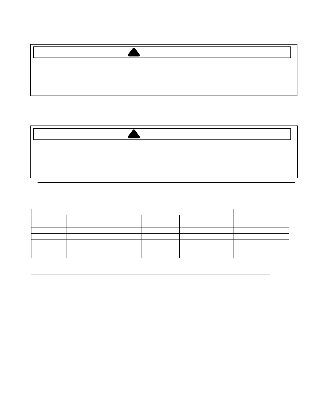
#44
Vent ScrewBurner Orifice Spud
GAS Input
• When converting the dryer gas valve to Natural gas, be sure the incoming gas supply line is equipped with a
pressure regulator (located ahead of the dryer) that will maintain the gas supply to the dryer at 6.5 ± 1.5 inches
(16.5 ± 3.81 cm) water column pressure. Remove pressure tap pipe plug and check gas pressure by connecting
a “U” tube manometer (or similar pressure gauge) to the pressure tap.
− 20,000 BTU/HR
Equipment
shut-off valve
within 6' (1.8 m) of dryer.
Manometer
6.5 + 1.5"
(16.5 + 3.81 cm)
1/8" NPT pipe plug
(for checking inlet
gas pressure)
Install the No. 402P3 Kit as follows:
1. Disconnect electrical power to the machine.
2. Turn the equipment shut-off valve handle to the closed position (if so equipped). If shut-off valve is not present,
turn off dryer gas supply at the appliance.
3. Gain access to burner housing by following Step “a” for early models or Step ”b” for later models.
a. Apply thumb pressure to the right side of the access door. When door opens, move door to the left to
disengage from the door supports.
Early Models
Apply pressure
here
Service Access Door
b. Remove lower access panel by removing two access panel screws.
Amana Appliances 11/03/00 Part No. 401158012
Later Models
Service Access Panel
screws
Page 3

Instructions for Installing No. 402P3
Natural Gas Conversion Kit
4. Disconnect ignitor wires at quick disconnect blocks.
Ignitor Quick
Disconnect
Burn er Orifice
Spud
Shut-Off
Valve
4 5
1 - 3
Block
Vent Screw
Air Shutter
Adjustment
Screw
Burner Housing
Burner Tube
Hex Head Screw
Air Shutter
Apply No. 40114601 Valve
Converted Sticker Here
5. Remove hex head screw holding burner tube and ignitor in place.
6. Carefully move burner tube toward rear of dryer, far enough to permit removal of burner orifice spud from gas
valve.
NOTE:
7. Turn the burner orifice spud out of gas valve and install No. 40114405 Natural Burner Orifice Spud
8. Reinstall burner tube, tighten hex head screw firmly and reconnect ignitor leads.
9. Remove the Block-Open Plug, and insta ll No. 40115 901 Ve nt Sc r e w.
10. Install No. 40114601 “Valve Converted to Natural Gas” Sticker to top side of gas valve, so it covers the gas
11. In Canada, early models (with access door) do not need to use the two 40096607 Natural Gas Stickers, and
Tab on burner tube may have to be removed from slot in burner housing to obtain enough clearance.
(metal stamped # 44). Torque new burner orifice spud to 30 inch-pounds (3.4 N-m).
valve part number.
they can be discarded. All other models, including later Canadian models (with lower access panel), will need to
apply the two 40096607 Natural Gas Stickers.
Sign and date each of the two No. 40096607 Natural Gas Stickers. Install one of the 40096607 Natural Gas
Stickers over the top three lines of the old sticker on rear of cabinet, then place the second sticker over the top
three lines of the old sticker located on backside of access door or lower access panel.
1/ 8" Pipe Plug
(For checking manifold pressure)
Amana Appliances 11/03/00 Part No. 401158013
Apply No. 40096607
Natural Sticker Here
Page 4

Instructions for Installing No. 402P3
!
Natural Gas Conversion Kit
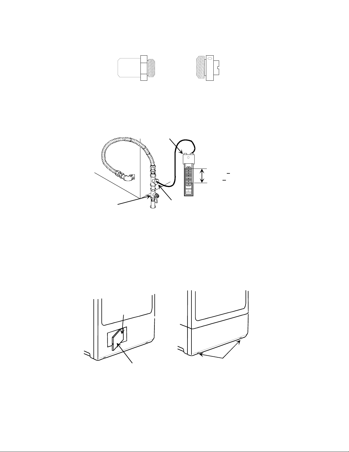
12. Apply the No. 40097005 Conversion Plate to the inside of the loading door opening, or over the top of any
previously applied conver s ion plate.
Earlier Models
Other Models
Canadian
Models
Apply No.
40097005
conversion
plate here
13. Turn the equipment shut-off valve handle to the open position, and connect electrical service.
14. Check gas valve pressure as follows:
a. Remove pressure tap pipe plug.
b. Connect a “U” tube manometer (or similar pressure gauge) to the pressure tap.
Shut-Off
Valve
Apply No.
40097005
conversion
plate here
Nameplate
Air Shutter
Adjustment
Screw
Manometer
Later Models
Nameplate
Apply No.
40097005
conversion
plate here
3.5 + .2"
Air Shutter
1/ 8" Pipe Plug
(For checking manifold pressure)
c. Start dr yer, press ure shou ld be 3.2 ± .2 inches (8.9 ± .5 cm).
d. Stop dryer and remove “U” tube and reinstall the pressure tap pipe plug.
(8.9 + .5 cm)
WARNING
To reduce the risk of fire or explosion, check pipe connection for gas leaks by using a soapy solution.
DO NOT USE AN OPEN FLAME TO CHECK FOR GAS LEAKS!
15. Check the gas line connection for gas leaks with a non-corrosive leak detection fluid.
16. Make sure the dryer conversion has been completed. Recheck the following:
Installed correct orifice spud (40114405, # 44), see Step 7.
Installed block-open plug, see Step 9.
Gas valve pressure must be 3.2 ± .2 inches (8.9 ± .5 cm), see Step 14.
Installed four stickers, see Steps 10, 11, and 12.
Amana Appliances 11/03/00 Part No. 401158014
Page 5

Instructions for Installing No. 402P3
!
Natural Gas Conversion Kit
17. Start the dryer and observe the burner flame. Adjust the air shutter to obtain a soft, uniform blue flame. (A lazy,
yellow tipped flame indicates lack of air. A harsh, roaring, very blue flame indicates too much air.) Adjust the air
shutter as follows:
a. Loosen the air shutter lockscrew.
b. Turn the air shutter to the left to get a luminous yellow tipped flame, then turn it back slowly to the right to
obtain a steady soft blue flame
c. After the air shutter is adjusted for the proper flame, tighten the air shutter lockscrew securely.
18. Be sure and observe at least two complete ignition and burn cycles before reinstalling the access door or lower
access panel.
19. Reinstall the access door or lower access panel.
WARNING
For personal safety, access door or lower access panel must be in place during normal operation.
No. 402P3 Natural Gas Conversion Kit for “AG, BG, KG, KGE, KGM, LG, LGD, SGD, NG, VG
and ZGM” Model/Series Dryers
Amana Appliances 11/03/00 Part No. 401158015
 Loading...