

Page 1

Model 9980 Self-Propelled
Peanut Combine
MAN141.rev1
1st Edition, Beg. Serial #530000
September 2015
©2015
Updated August 2016
Page 2

P.O. Box 1833
P.O. Box 3687
Model 9980 Self-Propelled Peanut Combines are manufactured
by Amadas Industries:
You can find us on the Web at:
www.amadas.com
or e-mail us at:
1100 Holland Road
(757) 539-0231 (Phone)
(757) 934-3264 (FAX)
Suffolk, VA 23439
(mailing)
Suffolk, VA 23434
(shipping)
Albany, GA 31701
(mailing)
1701 South Slappey Blvd.
Albany, GA 31706
(shipping)
(229) 439-2217 (Phone)
(229) 439-9343 (FAX)
Page 3

9980 Self-Propelled Peanut Combine Introduction
Table of
Contents
Welcome ................................................... v
1. Safety .................................................... 1
Safety at All Times! ............................... 2
Safety Practices .................................... 3
Additional Safety for this Machine ....... 10
Safety Decals ...................................... 15
2. Operator’s Station ............................. 21
Cab Access ......................................... 22
Cab Ladder .................................... 22
Cab Ladder Positions ..................... 23
Cab Landing Safety Chains ...... 24with
Washing Cab Windows, Servicing
Headlights and Wiper................. 25
Emergency Exit .............................. 26
Fire Extinguisher ............................ 26
Right-Hand Side Cab Access ......... 26
Operator Controls ............................... 27
Comfort Command Operator’s Seat 28
Seat Operation ............................... 29
Left-Hand Armrest and Seat Back .. 30
Right-Hand Armrest Control Console31
Seat Belts ....................................... 31
Steering Column ............................. 32
Gear Shift Lever ............................. 33
Manual Parking Brake .................... 34
Brake Pedals .................................. 34
Auxiliary Power Outlet Strip
and Service ADIVSOR Diagnostic
Connector .................................. 35
Field Office Seat ............................. 36
MAN141.rev1 08/05/16 i
Page 4

Introduction 9980 Self-Propelled Peanut Combine
Armrest Storage Box ...................... 36
Manual Storage .............................. 36
3. Operator’s Controls ........................... 37
General Overview ............................... 38
CommandTouch Armrest Console ...... 39
Header Engage/Header Reverse ... 40
Separator Engage .......................... 42
Header Height Control .................... 43
Road Transport Disconnect ............ 43
Engine Speed ................................. 44
10% Engine Speed Control ............ 44
Four-Wheel Drive ........................... 45
Operator Interface Controls ............ 46
Set Point Modes (Manual or
Automatic .................................. 47
Manual Modes ........................... 48
Feeder House Rate/Sensitivity
Adjust ........................................ 49
Header Speed ................................ 50
Cleaning Fan Damper .................... 51
Threshing Speed ............................ 52
Elevator Fan Damper Speed .......... 53
Multifunction Handle ........................... 54
Multifunction Handle Use ................ 55
Quick Stop Switch .......................... 56
Header Height Activation Button .... 57
Bin Lift ............................................ 58
Header Lift Switch .......................... 59
Conveyor Swing Switch .................. 60
Unloading Conveyor Drive Button... 61
Peanut Door Alarm………………….62
4. Overhead Control Panel ................... 63
Overhead Control Panel .................... 65
ClimaTrak Automatic Temperature
Control ....................................... 66
Mirror Control Switch ...................... 67
Mirror Heater Switch ....................... 68
Windshield Wiper Switch and
Optional Windshield Wiper ......... 69
Deere-Delco AM/FM Radios (Optional)70
Radio With Weatherband ............... 71
Setting Clock ............................. 71
General Receiver Functions....... 71
Turning on Power ...................... 71
Display ....................................... 71
Setting Default Displa y ............... 72
Adjusting Brightne s s of Displa y .. 72
Adjusting Receiver Settings ....... 72
Weatherband .................................. 73
Radio Programming for Local Area
Frequency .............................. 74
Radio with Weatherband and CD
Player...................................... 75
General Receiver Functions ....... 75
Turning on Power ....................... 75
One-Hour Timer ......................... 75
Display ....................................... 75
Programmable Eject Default ...... 76
CD Button Functions .................. 77
Playing a Compact Disc ............. 78
Operating Tips About Your Audio
System ....................................... 79
Understanding Radio Reception ..... 79
Antenna .......................................... 80
Communications/CB Radio Mounting80
5. CommandCenter Display .................. 83
CommandCenter ................................ 84
Display Navigation .......................... 84
Display Controls ............................. 85
Display Icons .................................. 86
Home Pages ...................................... 88
Select Machine Readings to
Display ......................................... 89
Manual Recording .............................. 90
Harvesting Information Pages ............ 91
Setup Pages ...................................... 93
Diagnostics and Calibration Pages ..... 96
Backlight Level Control and Boundary
Box Color ........................................ 98
Regional Settings, Time/Date Settings
Units of Measurement ................... 101
Diagnostic Readings, Tests .............. 104
Message Center ............................... 107
6. CommandTouch Cornerpost .......... 111
Cornerpost Monitors ......................... 112
Active Header Control Display ......... 113
Automatic Header Height Control
System ..................................... 114
Height Sensing and Active Header
Float Pressure Sensitivity ......... 115
Manual Raise/Lower Speed ..... 116
Header Height Resume ............ 117
Triple Tachometer Display ............... 122
Digital Display Lines ..................... 123
Fuel Gauge ................................... 124
Engine Coolant Temperature Gauge124
Warning Indicator Display ................ 125
ii 08/05/16 MAN141.rev1
Page 5

9980 Self-Propelled Peanut Combine Introduction
7. Calibration ........................................ 127
When to Calibrate ............................. 128
Error Codes ...................................... 128
Calibration Procedures ..................... 129
8. Cab Climate Control ........................ 131
System Overview .............................. 132
Sensors Monitored ........................ 132
CLIMATRAK Inlet Panel ................ 133
CLIMATRAK Precleaner ............... 133
Filters ............................................... 134
Fresh Air Filter .............................. 134
Recirculating Filter ........................ 135
Cleaning Filters ............................. 136
Troubleshooting ................................. 137
CLIMATRAK High Pressure Switch 137
CLIMATRAK Low Pressure Switch 137
9. Lights and Signals ........................... 139
General Information .......................... 140
Cab Interior Light ........................... 141
Turn Signals .................................. 142
Stop Lights .................................... 143
Light Switches .................................. 144
Dimmer Switch .............................. 145
Hazard Lights ................................ 146
Road Lights ................................... 147
Field Lights .................................... 148
Field Lights/Side Finder Lights.. 149
Stubble and Rear Residue Lights .. 150
Service Lighting ................................ 151
Engine Compartment Light ............ 151
Service Lights ............................... 151
Service Light Locations............. 152
Exit Lights ..................................... 153
10. Prestarting Checks ......................... 155
Read First ......................................... 156
Breaking in the Engine ...................... 157
First 50 Hours ............................... 158
Belt Drives Adjustment ............. 158
First 100 Hours ............................. 158
Break-in Check ......................... 158
Pre-start Daily Checks ...................... 159
Engine Oil ..................................... 159
Temperature ................................. 160
Hydrostatic/Hydraulic Oil Level ...... 161
Coolant Level ................................ 162
Fuel System .................................. 163
Fuel Tank Breather ....................... 164
Cleaning Engine Compartment ..... 164
Tires ............................................. 165
After Long Storage ....................... 165
11. Operation ........................................ 167
General Operation ........................... 168
Starting the Engine ....................... 168
Stopping the Engine ..................... 171
Cold Weather Operation .................. 172
Fuel Tank ..................................... 172
Fuel Tank Breather ....................... 172
Radiator ....................................... 173
Batteries ....................................... 174
Glow Plugs ................................... 175
Coolant Heater ............................. 176
Hot Weather Operation .................... 177
12. Transportation ............................... 179
Before Transporting ......................... 180
Driving the Combine on Roads ........ 181
Back-Up Alarm ............................. 185
Towing the Combine ........................ 186
Rear Tow Hook ............................ 187
Four-Wheel Drive ............................. 188
Read First ..................................... 188
Using Four-Wheel Drive ............... 189
13. Unloading Conveyor ...................... 191
Before Using the Conveyor .............. 192
Conveyor Safety ........................... 192
Using the Conveyor ......................... 193
Conveyor Tracking ........................... 195
Conveyor Maintenance .................... 196
Conveyor Troubleshooting ............... 197
Conveyor Timing .............................. 198
14. Performance ................................... 199
Cleaning Fan Damper ...................... 200
Overhead Teeth ............................... 202
Retention Board ............................... 203
Concave Teeth ................................ 204
10% Speed Control .......................... 205
Threshing Speed ............................. 206
Header Speed Control ..................... 207
Header Height Control ..................... 208
Elevator Fan Damper ....................... 209
Dual Speed Picking Cylinder Drive .. 210
15. Engine............................................. 211
Compartment ................................... 213
Rear Ladder and Landing ............. 213
Engine Access Covers ................. 213
MAN141.rev1 08/05/16 iii
Page 6

Introduction 9980 Self-Propelled Peanut Combine
Cleaning Engine Compartment ..... 213
Fuel System ..................................... 214
Engine Oil ..................................... 215
Fuel Tank ..................................... 216
Breather ................................... 216
Filling ....................................... 217
Draining ................................... 217
Electric Fuel Pump ....................... 218
Filters ........................................... 219
Primary Fuel/Water Separator
Filter ..................................... 219
Secondary Fuel/Water Separator
Filter ...................................... 219
Replacing Filters ...................... 220
Fuel System Bleeding................... 222
Cooling System ................................ 223
Important Information ................... 223
Radiator ....................................... 224
Surge Tank ................................... 225
Draining ........................................ 226
Filling ............................................ 227
Winterizing ................................... 228
Belts ................................................ 229
Shields ......................................... 229
Engine Belt ................................... 230
Replace Engine Accessory/Fan
Belt ....................................... 231
Replace Rotary Screen Drive
Belt ....................................... 233
Rotary Screen .................................. 234
Door ............................................. 234
Maintenance ................................. 235
Brush ............................................ 236
Air Cleaners Filters .......................... 237
16. Electrical System Service .............. 239
Electrical Safety ................................ 241
Basic Electrical Component
Handling .................................. 241
General Electrical Information ...... 242
Electrical Connectors ............... 242
Battery Safety ................................... 243
Battery Cables .............................. 245
Battery Charging .......................... 246
Specific Gravity Check ................. 247
Connecting Booster ...................... 248
Removing and Installing ............... 249
Battery Disconnect Switch ............ 250
Starter .......................................... 251
Alternator and Voltage Regulator . 251
Fuse Center ...................................... 252
Controller and Power Module
Locations ................................. 254
System Wakeup Power Fuse ........ 255
Glow Plug Fuse ............................ 255
Glow Plug Diagnostic System Fuse256
Halogen Lights .................................. 257
Replacing Bulbs ............................ 257
Replacing Cab Headlights ............ 258
Adjusting Cab Headlights ............. 259
Replacing Bulbs ................................ 260
Cab Interior Light .......................... 260
Side Finder Lights ......................... 260
Stubble, Rear Residue, and Work
Lights ....................................... 261
Tail and Stop Lights ...................... 262
Turn Signal Indicator Lights .......... 263
Warning Lights .............................. 263
Xenon (High Intensity Discharge)
Lights ............................................ 264
Replacing Xenon Lights ................ 265
Adjusting Xenon Lights ................. 266
Radio Installation ............................... 267
FM Radio ...................................... 267
17. Hydraulic System Service ............. 269
General Information........................... 270
Components ................................. 270
System Cleanliness ........................... 271
Accumulator ...................................... 272
Valve for Raising/Lowering Header272
Hydraulic Valve Assembly ................. 273
18. Ground Drive and Rear Axle Service275
Tires and Wheels .............................. 276
Care and Service of Tires ............. 276
Inflation Pressure .......................... 277
Changing Tire Radius ................... 277
Using Liquid Weight ...................... 278
Tire Loading Decal ....................... 279
Transporting ................................. 279
Drive Wheel Starter Stud .............. 279
Rear Wheel Bolt Torque ............... 280
Drive Wheel Bolt Torque ............... 280
Dual Wheel Bolt Torque ................ 281
Front Wheel Drive Offset .............. 282
Preparing Dual Wheels for Service283
Remove Front Wheels-Dual Wheels283
Install Front Wheels-Dual Wheels . 285
Single Attach Wide-Spaced Dual
Wheels ..................................... 288
Multifunction Control Handle Linkage
iv 08/05/16 MAN141.rev1
Page 7

9980 Self-Propelled Peanut Combine Introduction
Adjustment .................................... 289
Gearshift Linkage Adjustment ............ 290
Brake Fluid Reservoir ........................ 291
Jacking Location ................................ 292
19. Fuel and Lubricants ........................ 293
Read First .......................................... 295
Handling and Storing Diesel Fuel .. 296
Diesel Fuel ......................................... 297
Lubricity of Diesel Fuel .................. 297
Testing Diesel Fuel ....................... 297
Bio-Diesel Fuel .................................. 298
Blends Up to B20 .......................... 298
Blends Above B20 ......................... 299
Cold Weather Operation .................... 300
Diesel Engine Coolant ....................... 302
Warm Climates.............................. 303
Supplemental Coolant Additives .... 303
Additional Coolant Information ...... 304
Diesel Oil ........................................... 306
Break-In Oil ................................... 306
Diesel Engine Oil ........................... 307
Service Intervals............................ 308
OILSCAN, COOLSCAN ................ 309
Other Oils/Lubricants ......................... 310
Hydrostatic Drive, Main Hydraulics,
Main Engine Gearcase ............. 310
Transmission, Final Drives ............ 310
Grease .......................................... 311
Main, Variable Speed Gearboxes .. 311
Brake Fluid .................................... 312
Oil Filters ....................................... 312
Lubricant Storage .......................... 312
Alternative and Synthetic Lubricants313
Mixing of Lubricants ...................... 313
20. Lubrication and Maintenance ........ 315
Safety ................................................ 316
Cylinder Stop ................................ 316
9980 SP Combine with Dump
Bin ........................................ 317
9980 SP Combine with OCS .... 318
Maintenance and Lubrication Schedule319
Filters ............................................ 320
8 Hours or Daily ............................ 321
50 Hours or Weekly ....................... 323
200 Hours ..................................... 325
400 Hours or Yearly ...................... 327
800 Hours or Every Two Years ..... 332
2000 Hours ................................... 333
As Required .................................. 336
Cleaning Combine ............................ 337
21. Troubleshooting ............................ 339
Performance Troubleshooting ........... 340
Machine Troubleshooting .................. 343
Hydrostatic Ground Drive ......... 343
Four-Wheel Drive ..................... 346
Steering ................................... 346
Brakes ..................................... 347
Engine ..................................... 347
Heater ...................................... 352
Air Conditioner ......................... 353
22. Diagnostic Codes........................... 355
Access Diagnostic Trouble Codes..... 356
Access Diagnostic Trouble Code
Menu ....................................... 357
Select Controller ........................... 358
Display List of Controllers ........ 358
Display All Codes for All
Controllers ............................ 359
Return to Main Menu .................... 360
About Trouble Codes.................... 361
Diagnostic Trouble Codes ................. 362
ADU: Armrest Display Unit ........... 362
CAB: Control Unit CAB and Cab
Power Module .......................... 363
CDU: Cornerpost Display Unit ...... 368
ECU: Engine Control Unit ............. 369
LC1: Control Unit LC1 and Left
Power Module 1 ....................... 374
LC2: Control Unit LC2 and Left
Power Module 2 ....................... 379
RCU: Control Unit RCU and Right
Power Module .......................... 381
SSU: Control Unit SSU ................. 385
23. Combine Storage ........................... 389
Preparing Combine for Storage ......... 390
Prepare the Air Conditioner .......... 390
Prepare the Engine ...................... 391
Prepare the Combine ................... 393
Removing Combine from Storage ..... 394
Appendices ......................................... A - 1
A. Identification Plates .................... A – 2
Machine Identification Number ... A - 2
Engine Gearcase ...................... A – 2
Engine Serial Number ............... A – 2
Hydrostatic Drive Unit Pump ..... A – 2
Hydrostatic Drive Unit Motor ...... A – 3
MAN141.rev1 08/05/16 v
Page 8

Introduction 9980 Self-Propelled Peanut Combine
Cam Lobe 4-Wheel Drive Motor A – 3
B. Help Prevent Crime .................... A – 4
Record Identification Numbers .. A – 4
Keep Proof of Ownership .......... A – 4
Park Indoors .............................. A – 5
Park Outdoors ........................... A – 5
Reduce Vandalism .................... A – 6
Report Thefts ............................ A – 6
C. Torque Values ............................ A – 7
Metric Bolt and Cap Screw
Torque Values ........................ A – 7
Unified Inch Bolt and Cap
Screw Torque Values ............. A – 8
D. Circ uit Code Listing .................... A – 9
E. Hydraulic Hose Routing ............ A – 10
Form 0340 ................................ A – 11
Form 0341 ................................ A – 24
F. Schematics ............................... A – 34
Warranty Statement
vi 08/05/16 MAN141.rev1
Page 9

9980 Self-Propelled Peanut Combine Introduction
Welcome
To
AMADAS
Industries
With origins dating back to 1963, AMADAS
Industries and its predecessors have a long
history of providing high quality, reliable,
and innovative equipment for the farming
industry. AMADAS equipment is currently
at work throughout the United States and in
many other countries. This equipment
ranges fr om t h e Pull-Type Peanut Combine,
Tree Bark Processing and Packaging
Machinery, Hi-Speed Cotton Stalk
Puller/Chopper, Reel Rain Traveler
Irrigation Systems, to the 9980 SelfPropelled Peanut Combine.
Thank you for choosing AMADAS
Industries. We are strongly committed to
your satisfaction and safety. Our goal is for
you to be satisfied with our machinery for
many years and it is our hope that you will
choose AMADAS again for your equipment
needs.
One of the most important factors in both
safety and maximum performance is for
every machine operator to understand
thoroughly the safe operation of this
equipment. Please invest in the time to
read this manual to ensure that injuries are
prevented, and also to receive the
maximum productivity from your AMADAS
machine.
MAN141.rev1 08/05/16 vii
Page 10
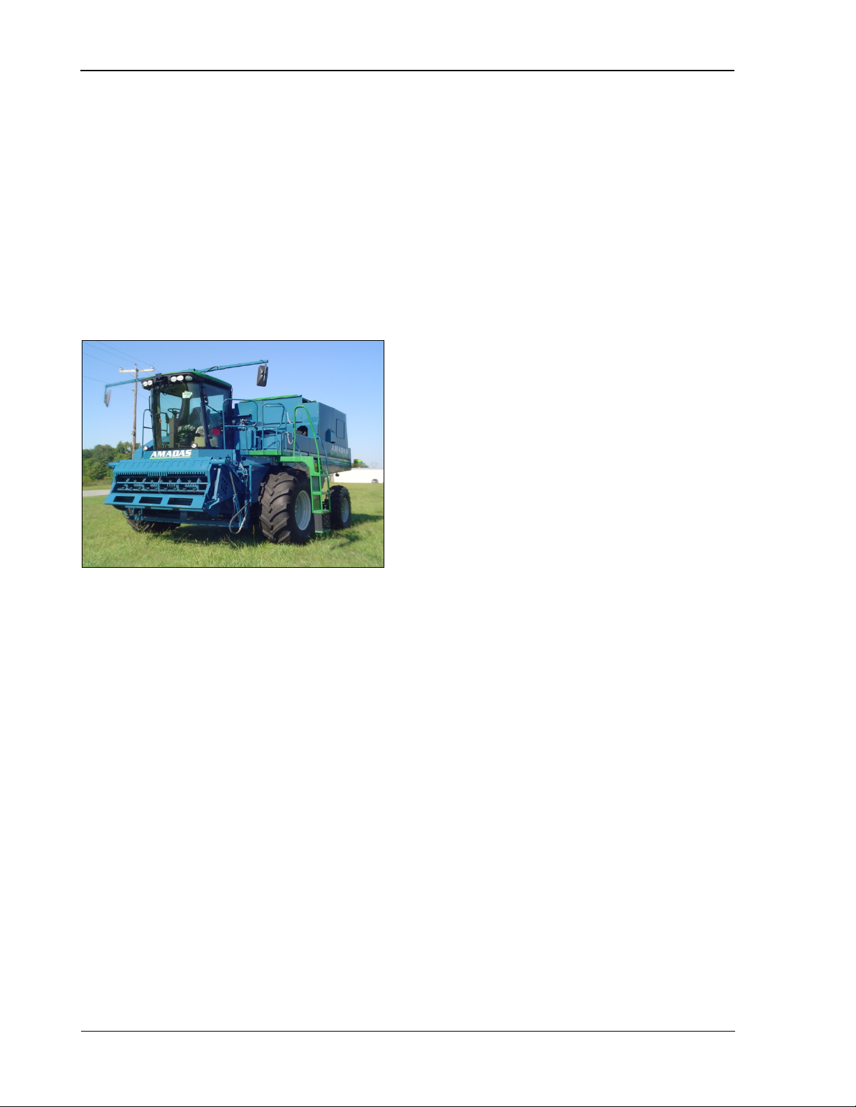
Introduction 9980 Self-Propelled Peanut Combine
• Reduced crop damage and loss. Up
Model 9980
Self-Propelled
Peanut
Combine
to 15% less crop is lost or damaged
than with the use of a pull-type combine.
• Reduced overall harvest costs. You
need fewer machines, fewer people,
and less fuel, all of which result in more
profit.
• Increased harvesting capacity. The
9980’s harvesting capacity is over 33%
greater than that of a comparable pulltype combine.
• Higher crop yield. Because the 9980
allows you to plant narrow row widths,
you will have higher crop yield.
• Superior harvesting capability in
adverse conditions. The 9980 is
unsurpassed in performance in wet,
muddy, and windblown conditions.
Congratulations on your purchase of an
AMADAS Model 9980 Self-Propelled
Peanut Combine. The 9980 SP is the
culmination of years of intensive research
and development in a combined effort by
AMADAS Industries and John Deere.
AMADAS Industries’ aggressive design
capabilities joined forces with John Deere’s
drive train expertise to produce the world’s
first eight-row self-propelled peanut
combine. The 9980 SP employs innovative
technology along with the industry’s largest
threshing and separation capacity to make it
the leader in peanut combines.
Benefits
A high-capacity, self-propelled combine is
the best machine for harvesting peanuts.
Your AMADAS combine will optimize your
peanut harvest by providing the following
benefits:
Standard Features
The following items are just some of the
features that come standard on the
AMADAS Model 9980 Self-Propelled
Peanut Combine.
• Turbocharged, air-to-air after cooled,
9.0L, 320 HP engine
• Hydraulic, variable 3-speed ground drive
• 7,500 lb (3,400 kg) capacity peanut bin
• 5-cylinder separation system
• Two-speed primary picking system
• Variable speed secondary picking
system
• 12” diameter collection auger.
Options
The following options are available with the
Model 9980:
• Two- or four-wheel drive
• Off-loading Conveying System (OCS) or
dump basket
• 6-, 8-, or 10-row header.
viii 08/05/16 MAN141.rev1
Page 11

9980 Self-Propelled Peanut Combine Introduction
Length
Inches (CM)
Width
Inches (CM)
Height
Inches (CM)
Weight
Pounds (KG)
Specifications (NOTE: Dimensions shown are for a dump basket equipped
combine.)
Dimension
Combine 318 (808) 203 (516) 174 (442) 32,000 (14,550)
Shipping 318 (808) 144 (366) 140 (355) 28,300 (12,800)
6/8 row header 227 (576) 52 (132) 51 (130) 4,100 (1,860)
8/10 row header 304 (772) 52 (132) 51 (130) 5,300 (2,400)
Basket (Dump) 203 (516) 96 (244) 77 (195) 4,000 (1,800)
Engine
Type .... Turbocharged, air-to-air after cooled
Cylinders ................................................... 6
Displacement ........................................ 9.0L
Horsepower ............... 320 HP @ 2200 RPM
High Speed Idle ......................... 2340 RPM*
*with Separator engaged ....... 2200 RPM**
**adjustable from 1950 RPM – 2200 RPM
while in harvesting mode
Mid Idle ....................................... 1690 RPM
Low Idle ....................................... 1200 RPM
Ground Drive
Type ................................ Hydraulic variable
Transmission ................................... 3-speed
Tires
Main drive (front) 800/65R32
30.5x32 16 ply
Steering (2-wheel drive) 18.4x26 10 ply
Steering (4-wheel drive) 18.4x26 10 ply
Capacities
Fuel tank .............................. 250 gal (950 L)
Cooling system ......................... 36 qt. (84 L)
Engine crankcase .................. 30 qt. (28.5 L)
Transmission ........................... 10 qt. (9.5 L)
Final Drives ............................... 9 qt. (8.5 L)
Engine gear case ..................... 17 qt. (16 L)
Hydraulic fluid ........................... 36 qt. (34 L)
Peanut bin ...................... 7,500 lb (3,400 kg)
Separation Syst em
Type ................ Disc separator supplied by a
14in. (35 cm) cross induction
fan, 5 retractable spring
overhead separator cylinders
with stripper cylinder
Threshing System
Type .......... 10% variable speed engine, and
2 speed sprockets for first three cylinders,
variable speed for last two cylinders, 5
spring-toothed cylinders with stripper
cylinder, adjustable retention board, and
adjustable breast spring bars
Cylinder diameter ................... 30 in. (76 cm)
Section width ...................... 103 in. (259 cm)
Collection System
Auger diameter ....................... 12 in. (30 cm)
Pneumatic Conveyor
Area ......................... 84 sq. in. (0.054 sq. m)
Fan diameter .......................... 28 in. (71 cm)
MAN141.rev1 08/05/16 ix
Page 12

Introduction 9980 Self-Propelled Peanut Combine
NOTES
x 08/05/16 MAN141.rev1
Page 13

9980 Self-Propelled Peanut Combine Safety
1.
Safety
Safety at All Times! ............................... 2
Safety Practices .................................... 3
Additional Safety for this Machine ....... 10
Safety Decals ...................................... 15
This symbol means:
ATTENTION!
BECOME ALERT!
YOUR SAFETY IS INVOLVED!
MAN141 09/16/15 1
Page 14
Safety 9980 Self-Propelled Peanut Combine
Safety at All Times!
DO THAT JOB.
Look for the Safety Alert S ymbol!
Safety Signal Words Used
Safety Decals
any safety sign or warning decals.
Shields
You, the operator, can help avoid accidents
or injury by observing the precautions in
this section and insisting that others
working for or with you also follow them.
• Do NOT attempt to operate this
equipment under the influence of drugs
or alcohol, or prescription/over-thecounter drugs that may cause
impairment.
• T his equipment is dangerous to
children and persons unfamiliar with its
operation. They should never be
allowed to operate this machinery or
remain in its vicinity while in operation.
• Only a trained operator familiar with this
machinery and trained in its operation
should be allowed to operate this
machine. Do NOT allow any person to
operate or perform maintenance on this
machine until he or she has read this
manual and understands the safety
precautions.
• T o prevent injury or death, use a tractor
equipped with a Rollover Protective
System (ROPS).
• NEVER exceed the limits of a piece of
machinery. If its ability to perform a job
safely is in question, DO NOT TRY TO
• Cert ain photographs or illustrations in
this manual may show a safety shield
removed. However, NEVER operate
this machine without all shields
correctly in place!
• If a shield must be removed to make a
repair or adjustment, replace the shield
prior to use.
The Safety Alert Symbol indicates a potential
safety hazard to personnel and that extra
precaution must be taken. When you see this
symbol on the machine, remain alert and
carefully read the message that follows it.
ALWAYS follow the recommended
precautions and safe operating procedures
accompanying this symbol. If you have any
questions, please contact your dealer or the
manufacturer.
Three safety signal words are used on the
machine and in this manual to indicate the
degree or level of hazard seriousness. These
three words are:
DANGER
Indicates an imminently hazardous situation
that, if not avoided, will result in death or
serious injury. This signal word is to be
limited to the most extreme situations,
typically for machine components that, for
functional purposes, cannot be guarded.
WARNING
Indicates a potentially hazardous situation
that, if not avoided, could result in death or
serious injury, and includes hazards that are
exposed when guards are removed. It may
also be used to alert against unsafe practices.
• Repla c e a n y CAUT ION, WARNING,
DANGER, or instruction safety decal
that is not readable or is missing.
• Do NOT paint over, remove, or deface
2 09/16/15 MAN141
CAUTION
Indicates a potentially hazardous situation
that, if not avoided, may result in minor or
moderate injury. It may also be used to alert
against unsafe practices.
Page 15
9980 Self-Propelled Peanut Combine Safety
Transport Machine Safely
adequate control of steering and stopping.
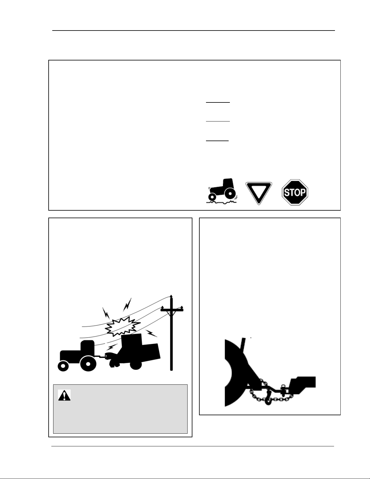
Avoid Electrical Power Lines
electrical cables, during transport.
DANGER
Use a Safety Chain
NOTE! This section covers general safety. Some items may not apply to this type of machine.
Safety Practices
• Comply with state and local laws.
• Be familiar with tractor operations and
follow all safety instructions in the tractor’s
manual.
• Before moving away, always check
immediate vicinity (e.g., for children).
• NEVER exceed a maximum speed of 20
MPH.
• Always adapt ground speed to road or
field conditions, making sure you have
• Avoid sharp turns, holes, ditches, and
obstructions which may cause the tractor
to tip, particularly on hillsides.
• Make sure all components are secured in
the proper position before transporting
machine (for example: basket bin lip
extension, mower deck, off-loading
conveyor, etc.).
• AVO ID all lines, particularly low-hanging
• Use following tow load weight ratios as
guidelines:
20 MPH when weight is less than or
equal to the weight of the tractor
10 MPH when weight is more than
weigh t of the tr actor
• NEVER t ow a load more than double the
weigh t of the tr actor!
• Sudden braking can cause a towed load
to swerve and upset. Reduce speed if
towed load is not equipped with brakes.
• Use a safety chain to help control
machinery if it separates from the tractor
drawbar.
• Use a chain with strength rating equal to
greater than the gross weight of the
towed machine.
Contact with electrical lines will cause the
operator to suffer severe electrical shock
or possibly death.
MAN141 09/16/15 3
• Attach the chain to the tractor drawbar
support, allowing only enough slack in
the chain for turning.
• Do NOT use a safety chain for towing.
Page 16
Safety 9980 Self-Propelled Peanut Combine
NOTE! This section covers general safety. Some items may not apply to this type of machine.
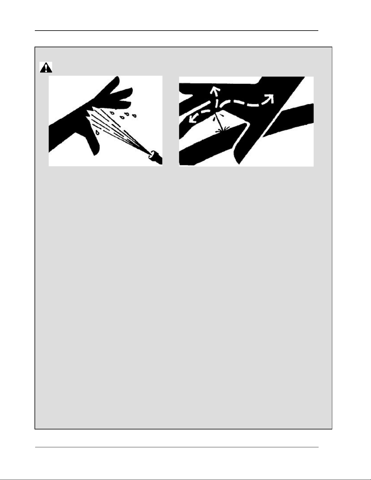
Avoid High Pressure Fluids
CAUTION
• Use extreme care when working with
hydraulic components and high pressure
sprays.
• Escaping fluid or spray under pressure can
penetrate the skin, causing serious injury.
• T o avoid injury, relieve pressure before
disconnecting hydraulic or other lines.
• Tight en all connections before applying
hydraulic or spray pressure.
• Search hoses/connections for leaks with a
piece of cardboard.
• Take appropriate safety measures to
protect hands, body, and face from high
pressure fluids.
• Always wear appropriate safety gear to
protect hands, body and face from
exposure to high pressure fluids.
• Never try to block the flow or search for
leaks of high pressure fluids with your
hands even if wearing gloves. High
pressure fluids can penetrate gloves as well
as your skin.
• Always avoid direct contact of any high
pressure fluid low.
• If an accident occurs, respond as follows:
o Seek medical treatment
immediately. Any fluid injected into
the skin must be surgically removed
within a few hours or gangrene may
result.
o Alert the medical professionals that
a fluid injection or high pressure
spray injury has occurred.
o Give inf ormation on the type of fluid
or spray and time the accident
occurred. If known, include the
amount of fluid injected and/or the
system injection pressure.
o Surgery will most likely be required,
so no food or drink for the affected
person.
Doctors unfamiliar with this type of injury
should reference a knowledgeable medical
source. Such information is available in
English from Deere & Company Medical
Department in Moline, Illinois, U.S.A., by
calling 1-800-822-8262 or +1 309-748-
5636.
VERY IMPORTANT!! Although in some
cases there is little or no pain from an
injection or high pressure spray accident,
THIS IS A SERIOUS EVENT THAT MUST
BE TREATED BY MEDICAL
PROFESSIONALS!!!
4 09/16/15 MAN141
Page 17
9980 Self-Propelled Peanut Combine Safety
Work in Ventilated Area
Handle Fuel Safety – Avoid
Wear Protective Clothing
NOTE! This section covers general safety. Some items may not apply to this type of machine.
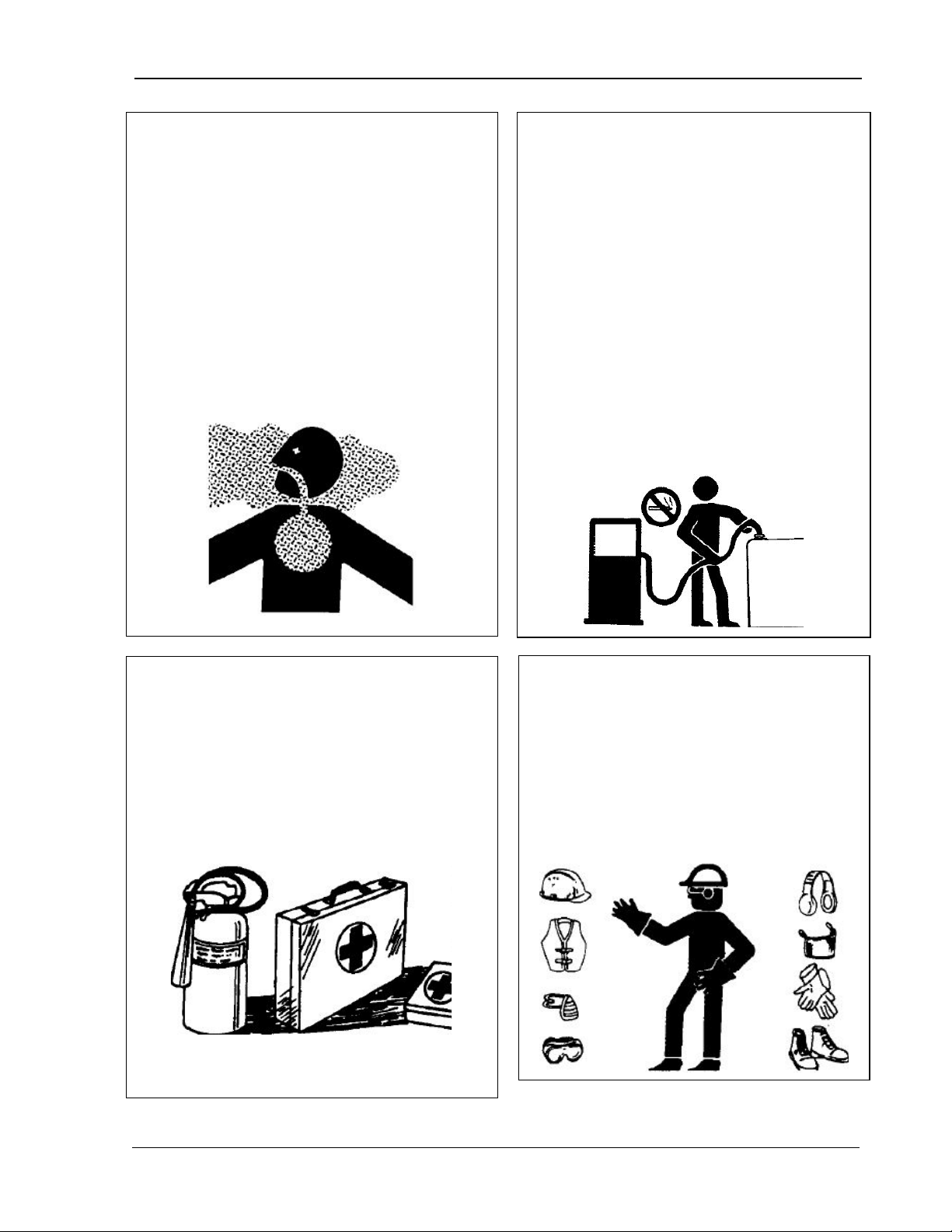
Engine exhaust fumes can cause sickness or
death.
• If it is necessary to run an engine in an
enclosed area, remove the exhaust fumes
from the area with an exhaust pipe
extension.
• If you do not have an exhaust pipe
extension, open the doors and get outside
air into the area.
AMADAS DOES NOT RECOMMEND
RUNNING ANY ENGINE IN AN ENLCOSED
AREA EVEN WITH VENTILATION.
Fires
• Handle fuel with care; it is highly
flammable.
• Do NOT refuel the machine while
smoking or when near open flame or
sparks.
• Always stop engine before refueling
machine.
• Fill f uel tank outdoors.
• Prevent fires by keeping machine clean
of accumulated trash, grease, and
debris.
• Always clean up spilled fuel.
Prepare for Emergencies
• Be prepar ed if a fire starts.
• Keep a first aid kit and fire extinguisher
handy.
• Keep emergency numbers for doctors,
ambulance service, hospital, and fire
department near your telephone.
• Wear clo se-fitting clothing and safety
equipment appropriate to the job.
• Oper ating equipment safely requires
the full attention of the operator. Do
NOT wear radio or music headphones
while operating machine.
MAN141 09/16/15 5
Page 18
Safety 9980 Self-Propelled Peanut Combine
Handle Chemical Products
Avoid Contact with Moving Parts
Remove Accumulated Crop
engine, and remove key.
NOTE! This section covers general safety. Some items may not apply to this type of machine.
Safely
• Direct exposure to hazardous chemicals
can cause serious injury. Potentially
hazardous chemicals used with AMADAS
equipment include such items as
lubricants, coolants, paints, and
adhesives.
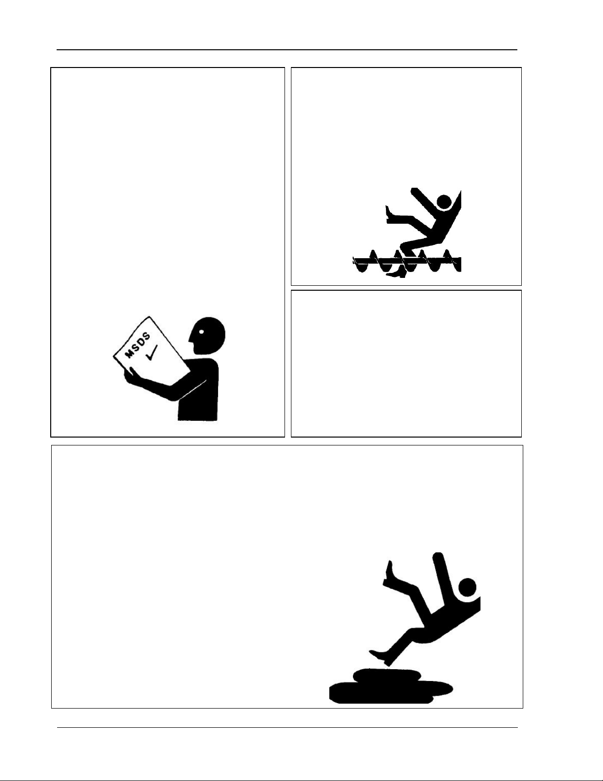
• Before you start any job using a
hazardous chemical, check the MSDS so
that you are aware of the risks and know
how to proceed safely. Carefully follow
all procedures, using only recommended
equipment.
• See your AMADAS dealer for MSDS on
chemical products used with AMADAS
equipment.
• Wear clo se-fitting clothing to avoid
entanglement with moving parts.
• Keep hands, feet, and clothing away
from power-driven parts.
• Never clean, lubricat e or adjust machine
when it is running.
Debris
• T he buildup of chaff and crop debris near
moving parts or heat sources is a
hazard.
• Check and clean these areas frequently.
• Before performing any inspection or
service, engage parking brake, turn off
Practice Safe Maintenance
• Underst and the service procedure before
doing work. Use proper tools and refer to
the User Manual.
• Keep service area clean and dry.
• Lower machine to ground, engage parking
brake, turn off engin e, and remove key
before performing maintenance.
• Allow time for the machine to cool
completely.
• Never lubricate, service, or adjust machine
while it is moving.
• Keep hands, feet, and clothing from powerdriven parts.
• Securely support any machine elements
that must be raised for service work.
6 09/16/15 MAN141
• Keep all parts in good condition and
properly installed.
• Fix any damage immediately; replace worn
or broken parts.
• Keep the machine free of any buildup of
grease, oil, or debris.
Page 19
9980 Self-Propelled Peanut Combine Safety
Avoid Using Heat Near
NOTE! This section covers general safety. Some items may not apply to this type of machine.
Keep Riders off of Machine
Riders are subject to injury such as
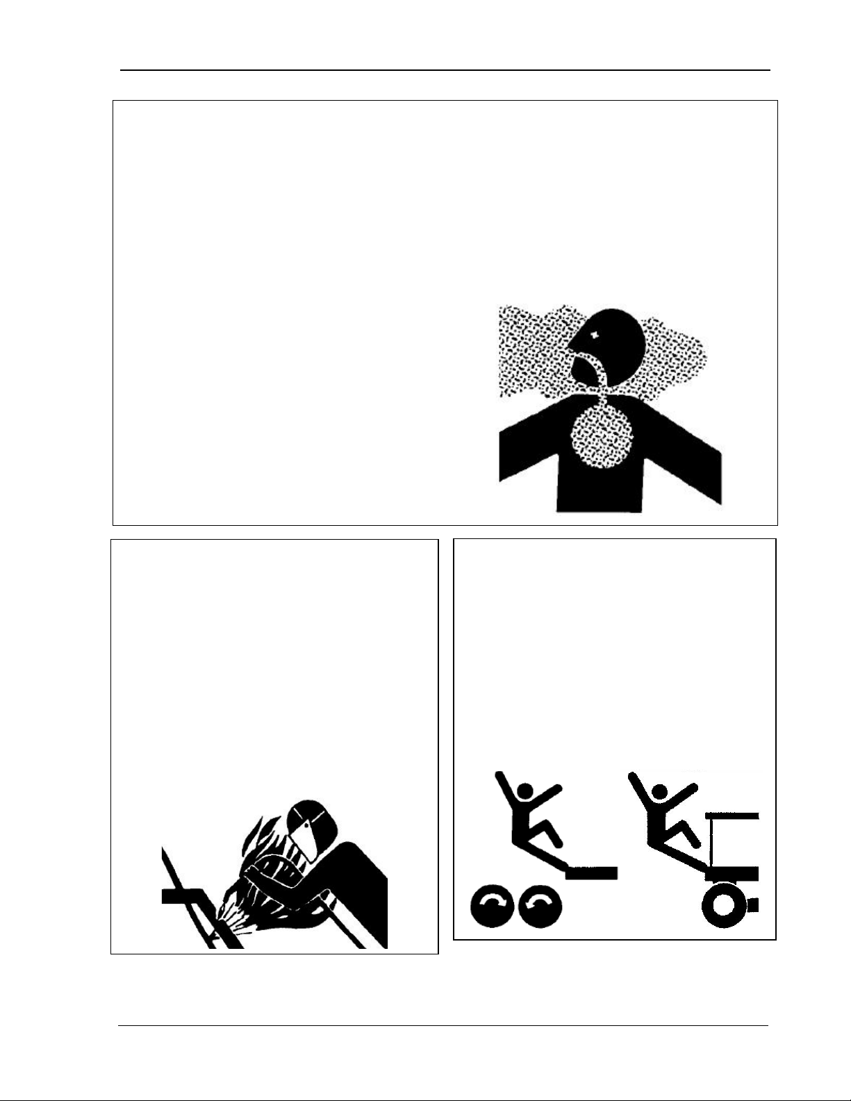
Remove Paint/Protec t ive Coating
Before Welding Or Heating
• Avoid potentially toxic fumes and dust.
• Hazardous fumes can be generated when
paint or coatings are heated by welding,
soldering, or by using a torch.
• Do all work outside or in a well-ventilated
area.
• Remove paint/coatings before welding or
heating:
o If you sand or grind paint, avoid
breathing the dust. Wear an approved
respirator.
o If you use solvent or paint stripper,
remove stripper with soap and water
before welding.
o Remove solvent or paint stripper
containers and other flammable
material from the area.
o Allow any fumes to disperse for at least
15 minutes before welding or heating.
• Do NOT use a chlorinated solvent in areas
where welding will take place.
• Do all work in an area that is wellventilated to carry toxic fumes and dust
away.
• Dispose of paint/coatings and solvent
properly.
Pressurized Fluid Lines
• Flammable spray can be generated by
heating near pressurized fluid lines,
resulting in severe burns to yourself and
bystanders.
• Do NOT heat by welding, soldering, or
using a torch near pressurized fluid lines
or other flammable materials.
Pressurized lines can accidentally burst
when heat goes beyond the immediate
flame area.
• Only allow the operator on the machine.
Riders obstruct the operator’s view,
which results in the machine being
operated in an unsafe manner.
•
being thrown off of the machine.
• Children should NEVER be allowed on
the machine.
MAN141 09/16/15 7
Page 20
Safety 9980 Self-Propelled Peanut Combine
Support Machine Properly
Service Drive Belts Safely
NOTE! This section covers general safety. Some items may not apply to this type of machine.
Dispose Of Waste Properly
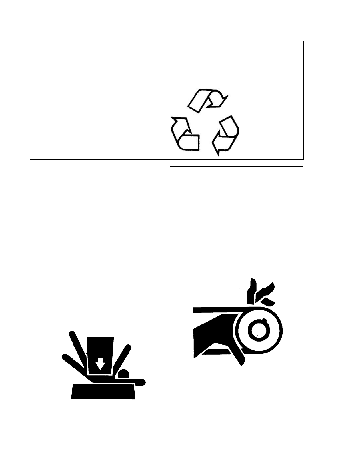
Improperly disposing of waste can threaten the
environment and ecology. Potentially harmful
waste includes items such as oil, fuel, coolant,
brake fluid, filters, and batteries.
• Use leak-proof containers when draining
fluids.
• Do NOT use food or beverage containers
that may mislead someone into drinking
from them.
• Do NOT pour waste onto the ground, down
a drain or into a water source.
• Always lower the attachment or implement
to the ground before you work on the
machine. If the work requires that the
machine or attachment be lifted, provide
secure support for them. If left in a raised
position, hydraulically supported devices
can settle or leak down.
• Do NOT support the machine on cinder
blocks, hollow tiles, or props that may
crumble under continuous load.
• Do NOT work under a machine that is
supported solely by a jack.
• Inquir e about the proper way to recycle or
dispose of waste from your local
environmental or recycling center, FEMA,
or from your AMADAS dealer.
When servicing drive belts, always observe
these precautions:
• Avoid serious injury from hand or arm
entanglement.
• Never attempt to clean, check, or adjust
belts while the machine is running.
Always shut off the engine, set the
parking brake and remove the key.
• Do NOT attempt to clean belts with
flammable cleaning solvents.
• Follow all safety procedures in this manual
for supporting the machine.
• When implements or attachments are used
with a machine, always follow safety
precautions listed in the implement or
attachment operator’s manual.
8 09/16/15 MAN141
Page 21
9980 Self-Propelled Peanut Combine Safety
Service Tires S afely
NOTE! This section covers general safety. Some items may not apply to this type of machine.
Pay Close Attention to Notes
either a "NOTE!" or "IMPORTANT!"
Please be sure to carefully read this
information, as it usually indicates a
situation that could cause machine
Maintain Your Machine
Use Safety Lights and Devices
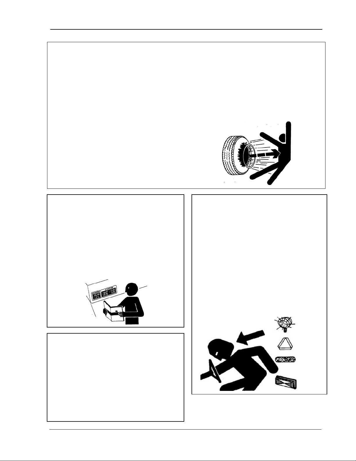
Explosive separation of a tire and rim parts
can cause serious injury or death.
• Do NOT attempt to mount a tire unless you
have the proper equipment and experience
to perform th e job.
• Always maintain the correct tire pressure.
• Do NOT inflate the tires above the
recommended pressure.
• Never weld or heat a wheel and tire
assembly. The heat can cause an
increase in air pressure resulting in a tire
explosion. Welding can structurally
weaken or deform the wheel.
• Throughout the manual, information that
needs to be emphasized is set apart with
heading.
•
damage.
• When inflating the tires, use a clip-on
chuck and extension hose long enough to
allow you to stand to one side and NOT in
front of over the tire assembly. Use a
safety cage if available.
• Check wheels for low pressure, cuts,
bubbles, damaged rims, or missing lug
bolts and nuts. NEVER fill a damaged tire
or one that is missing lug bolts or nuts.
Slow moving tractors, self-propelled
equipment and towed implements or
attachments can create hazards when
driven on public roads. They are difficult to
see, especially at night.
• Whenever you drive on public roads, use
flashing lights and turn signals according
to local regulations.
• T o increase visibility, use the lights and
devices provided with your machine.
• Keep safety items in good condition.
• Replace missing or damaged items.
• It is crucial you maintain your machine in
proper working condition.
• Perf orm all scheduled maintenance and
repairs in a timely manner.
• Do NOT perform unauthorized
modifications to the machine as these
could impair the function and/or safety of
the machine and affect machine life.
MAN141 09/16/15 9
Page 22
Safety 9980 Self-Propelled Peanut Combine
Drive the Combine Safely
Wear Seatbelt
Use Ballast for Safe Ground
Additional Safety for this Machi ne
• Oper ate the machine only when all guards
are correctly installed.
• Before moving away, always check
immediate vicinity of machine (e.g., for
children). Make sure you have adequate
visibility and use the horn as a warning
immediately before moving away.
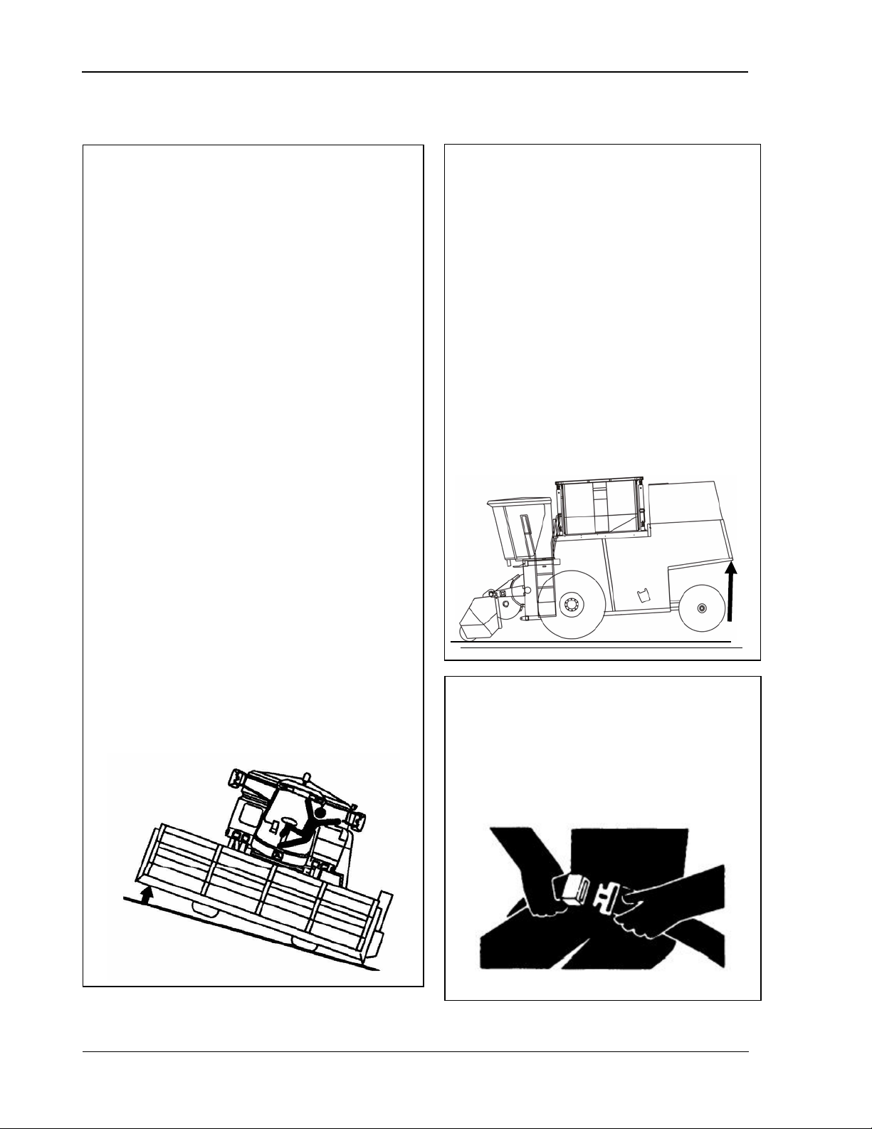
• Always adapt ground speed to road or
field conditions. Avoid making sharp turns
when driving up or down slopes or when
driving across a slope. Be especially
careful when turning on slopes and/or
when the combine has a full peanut bin.
• Follow all instructions in operating manual
for attaching or detaching the header.
Contact
• The operating, steering, and braking
performance of the combine can be
considerably affected by heavy front
end attachments which alter the
center of gravity of the combine.
• To maintain the necessary ground
contact, ballast the combine at the
rear end as necessary. (Fluid filling
the rear tires is the recommended
method of ballast.)
• Observe the maximum permissible
axle loads and total weights.
• When making turns, always take into
consideration the width of the attachment
and the fact that the rear end of the
machine swings out. Attachments and
ground conditions affect the driving
characteri stics of the combine.
• Reduce the ground speed when driving
on slope or over uneven ground and
before making sharp t urns. Shift to a
lower gear before descending a steep hill.
• Avoid holes, ditches, and obstructions
which may cause the combine to tip,
particularly on hillsides.
• Seatbelts are installed in the cab.
• Use the seatbelt whenever operating
the combine or when riding in the
combine as an observer.
10 09/16/15 MAN141
Page 23
9980 Self-Propelled Peanut Combine Safety
Stay Clear of Header
Park and Leave the Combine
Transport Combine Safely
on public roadways with the header
Drive at a speed that is safe for
• Whenever possible, avoid transporting
attached.
• If the combine must be transported with
the header attached, make sure that the
flashing warning lights on the header
are operating and the reflective material
is clean and visible.
• The use of a spotter or pilot vehicle is
recommended on busy, narrow or hilly
roads and when crossing bridges.
•
conditions.
• Secure the radio antenna and bin lip
extension in transport position before
driving on public roads.
• If equipped with unload-on-the-go,
make sure the conveyor is completely
pulled in and secured before driving on
public roads.
• AVOID electrical lines, particularly lowhanging electrical cables.
• Use the instructional seat for instruction
or short periods of machine observation
only. Do NOT allow children to ride in
the combine.
Safely
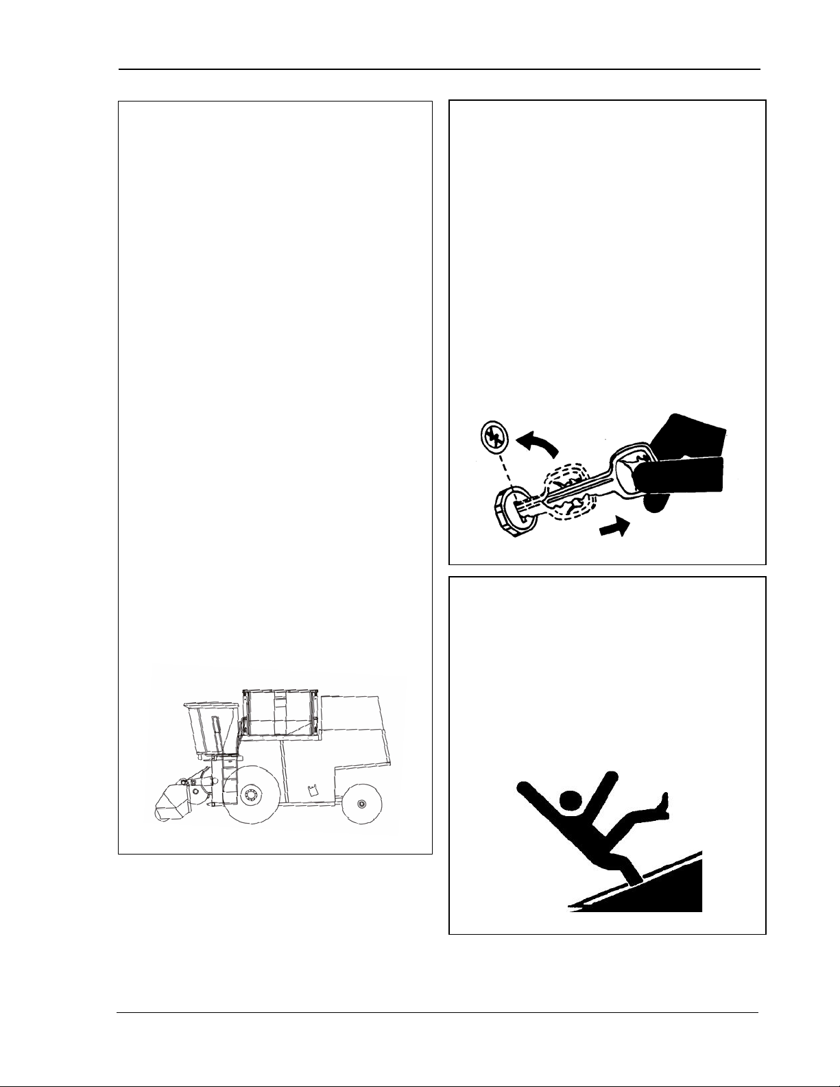
• Lower the header unit to the ground.
• Before leaving the machine, disengage
the harvesting unit and separator. Shut
the engine off and move the
multifunction control handle to the
neutral position. Apply the parking
brake, remove the key and lock the
operator’s cab.
• Never leave the machine unattended as
long as the engine is running.
• Never leave the operator’s cab when
driving.
• Many moving parts (such as the auger)
cannot be shielded due to function.
Stay clear of all moving elements during
operation.
• Always disengage the header drive,
shut off the engine and remove the key
before servicing or unclogging the
header.
MAN141 09/16/15 11
Page 24
Safety 9980 Self-Propelled Peanut Combine
Prevent Machine Runaway or
across the starter or solenoid terminals.
Clean Peanut Baskets and
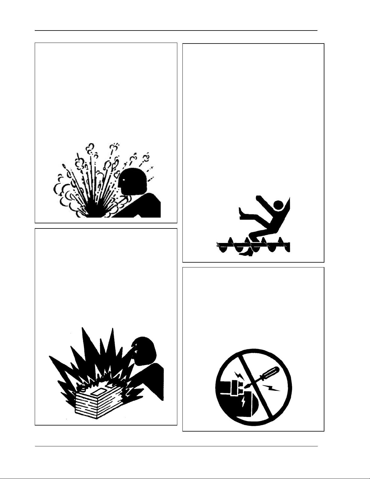
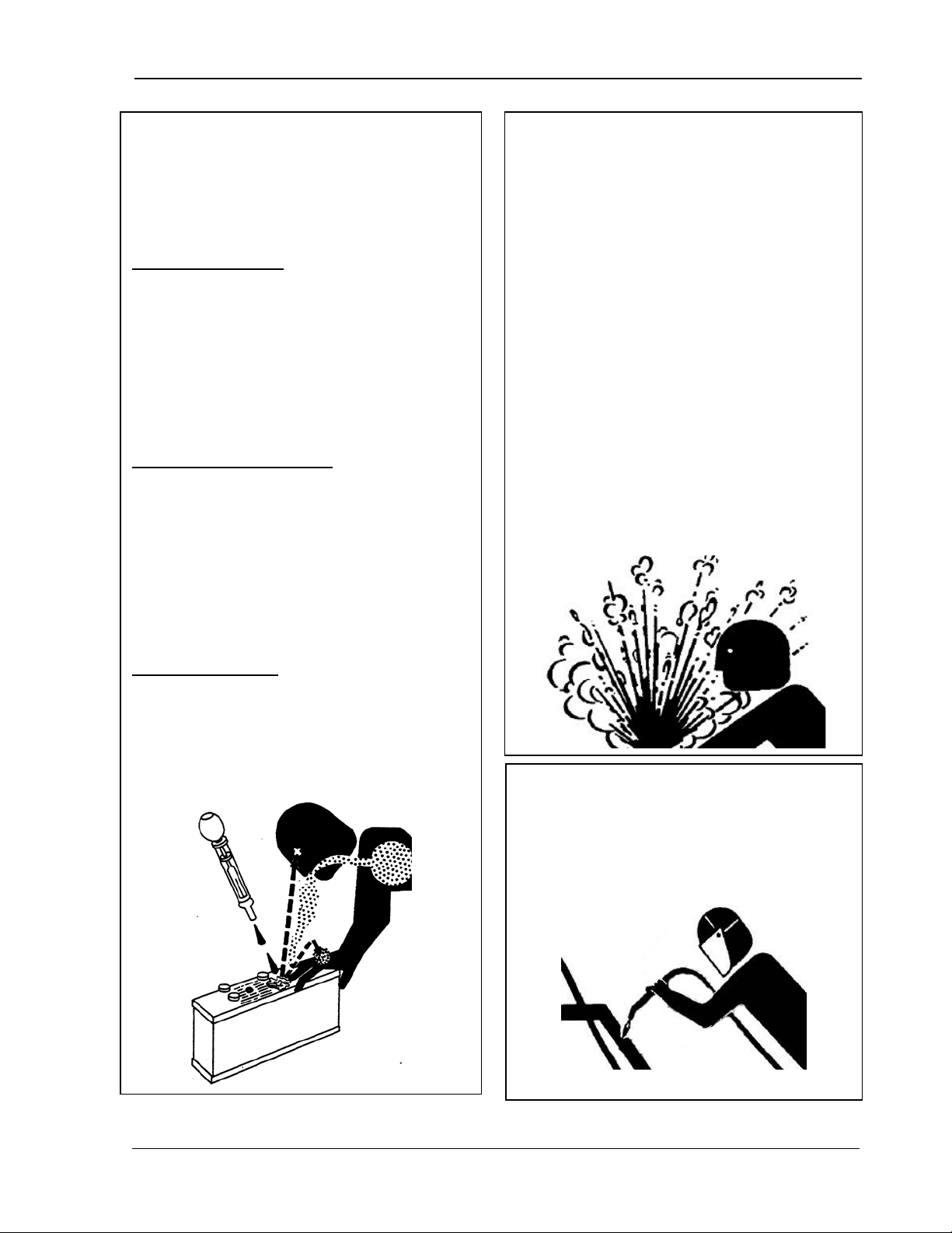
PREVENT BATTERY EXPLOSIONS
Service Cooling System Saf e ly
cooling system can cause serious burns.
Explosive release of fluids from pressured
Before servicing the cooling system:
• Shut off the engine, set the parking brake
and remove the key.
Remove Blockages Safely
• On OCS equipped combines, avoid
serious injury or death from
entanglement in peanut bin cross
augers.
• Allow the system to cool before opening
the cap.
• Slowly loosen the cap to relieve pressure
before removing completely.
• Keep sparks, lighted matches, and open
flame away from the top of the battery.
Battery gas can explode.
• NEVER chec k batter y charge by placing
a metal object across the posts. Use a
volt-meter or hydrometer.
• Do NOT charge a frozen battery; it may
explode. Always warm the battery to
16°C (60°F) before char ging.
• For functional purposes, the cross
augers cannot be completely covered.
• NEVER enter the peanut bin in either
dump bin or OSC combines when the
engine is running.
• Before entering the bin, ALWAYS:
o Shut t he engine OFF.
o Set t he parking brake.
o Remove the key from ignition.
Unexpected Movement
• Avoid injury or death from unexpected
movement of machine or components.
• Do NOT start the engine by shorting
The machine or components may move
if the normal circuitry is bypassed.
12 09/16/15 MAN141
Page 25
9980 Self-Propelled Peanut Combine Safety
Service Accumlator Systems
Prevent Acid Burns
Prevent Machine Damage When
Sulfuric acid in battery electrolyte is
poisonous. It is a strong enough to burn
skin, eat holes in clothing, and cause
blindness if splashed into eyes.
To avoid the hazard:
• Fill batter ies in a well-ventilated area.
• Wear eye protection and rubber gloves.
• Avoid breathing fumes when adding
electrolyte.
• Use proper jump start procedure.
If you spill acid on yourself:
• Flush your skin with water.
• Apply baking soda or lime to help
neutralize the acid.
• Flush your eyes with water for 15-30
minutes. Get the medical attention
immediately.
Safety
• Escaping fluid or gas from pressurized
hydraulic accumulator systems can
cause serious injury.
• Extreme heat can cause the
accumulator to burst, and pressurized
lines can be accidentally cut.
• Do NOT weld or use a torch near a
pressurized accumulator or pressurized
line.
• Relieve pressur e from the hydraulic
system before removing the
accumulator.
• Never attempt to relieve a hydraulic
system or accumulator pressure by
loosening a fitting.
• Accumulators cannot be repaired.
If acid is swallowed:
• Do NOT induce vomiting.
• Drink large amounts of water or milk, but
do not exceed 2 L (2 quarts).
• Get medical attention immediately.
Welding
To prevent damage to electronic
components, be sure to disconnect the
negative ground cable before welding on
combine.
MAN141 09/16/15 13
Page 26
Safety 9980 Self-Propelled Peanut Combine
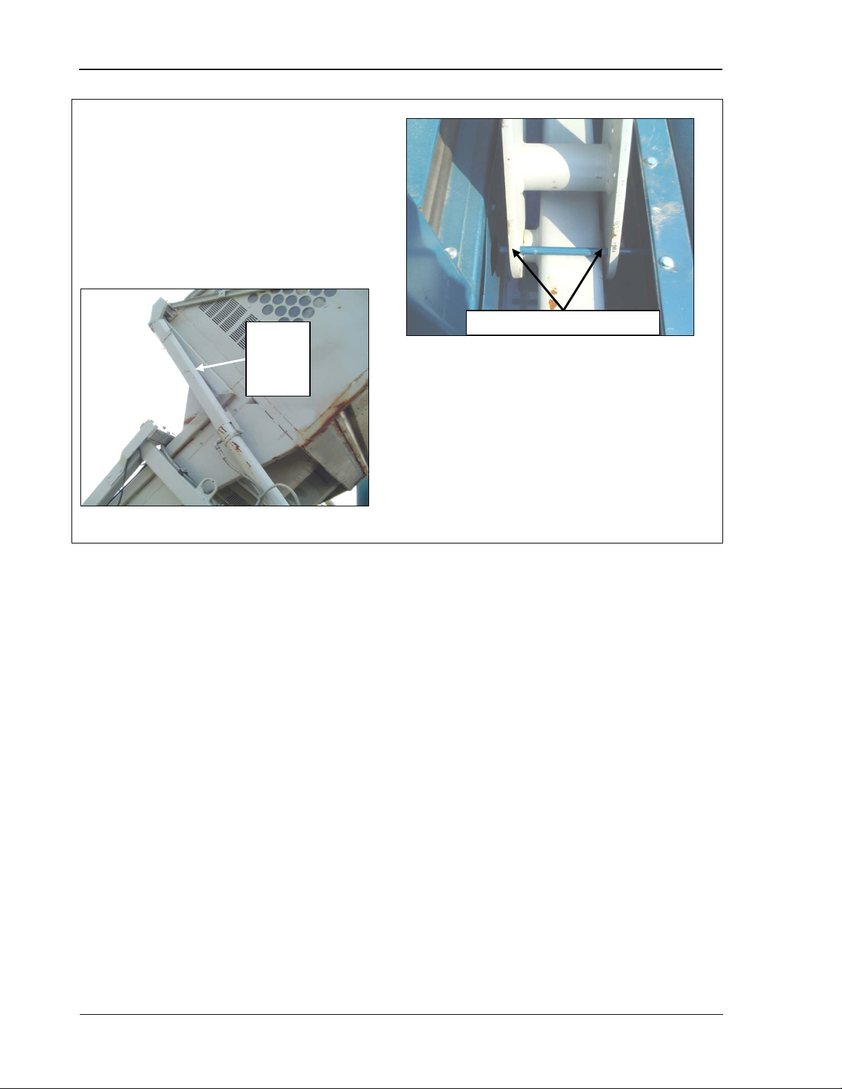
Set Cylinder Stop
Insert pin through both holes
Cylinder
• If maint enance is required under the bin
area, always make sure the engine is
turned off and the cylinder stop is set while
the bin is lifted.
• See Chapter 20, Lubrication and
Maintenance, for more information on
setting the cylinder stop.
stop
fully in
place
9980 SP Combine with Dump Bin
9980 SP Combine with OCS
14 09/16/15 MAN141
Page 27
9980 Self-Propelled Peanut Combine Safety
Safety Decals
is included on
Never remove a safety decal from the
When you replace a part with a safety
For replacement decals, call your
Replacement safety decals are available
Safety decals identify specific hazards, as well
as general safety. A signal word ( DANGER,
WARNING, or CAUTION)
each decal to alert you to the severity of the
hazard.
Please note the following about the decals:
• Keep them clean and legible.
•
machine.
•
decal, also replace that decal.
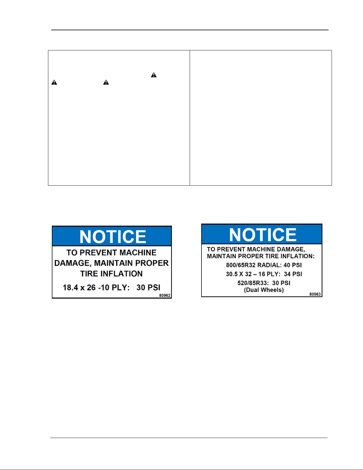
Tire Inflation Decals
•
AMADAS dealer.
•
free of charge.
Safety decals used on this machine are shown
on the following pages. Decal locations are
also included.
Decal #80962
MAN141 09/16/15 15
Decal #80963
Page 28
Safety 9980 Self-Propelled Peanut Combine
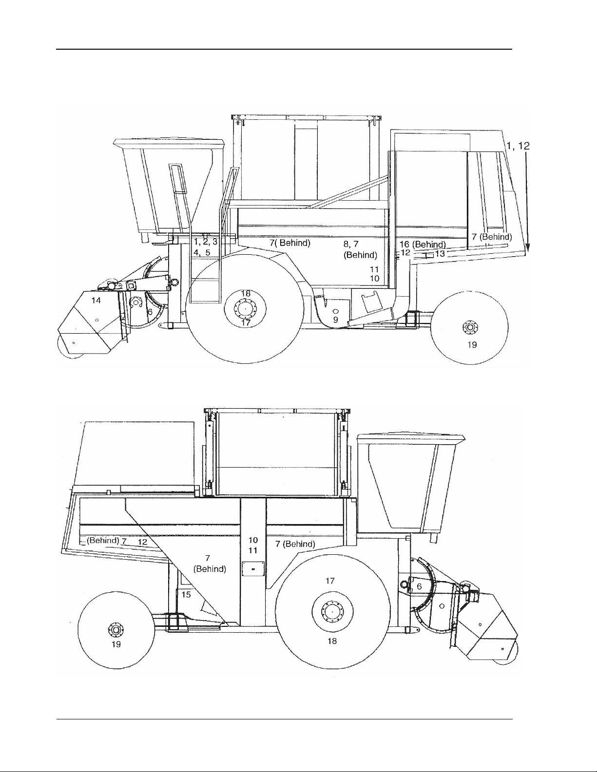
Decal Locations
(Numbers correspond to decals on following pages)
16 09/16/15 MAN141
Page 29

9980 Self-Propelled Peanut Combine Safety
Decals
1 Decal #H149064
2 Decal #E82510
4 Decal #80935
5 Decal #80945
3 Decal #80956
MAN141 09/16/15 17
6 Decal #JH149063
Page 30
Safety 9980 Self-Propelled Peanut Combine
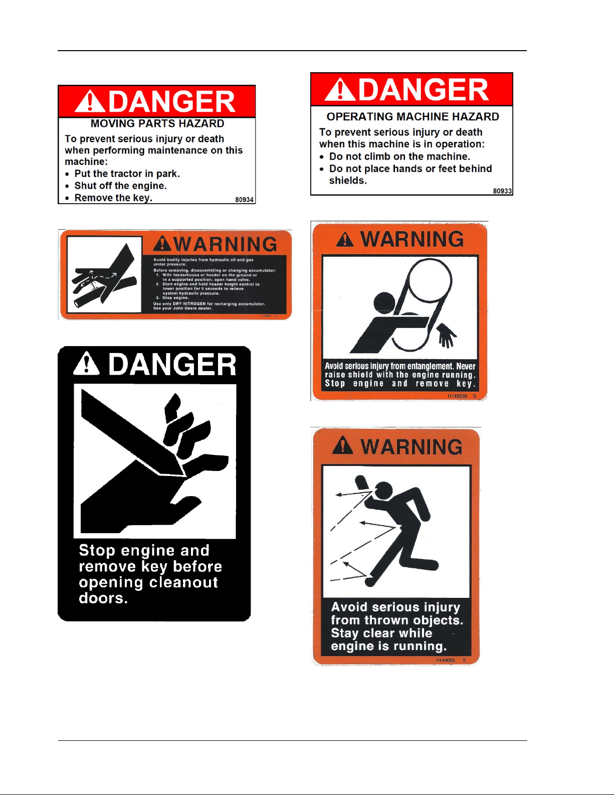
7 Decal #80934
8 Decal #H149067
10 Decal #80933
11 Decal #H149099S
9 Decal #H209453
12 Decal #H149096S
18 09/16/15 MAN141
Page 31
9980 Self-Propelled Peanut Combine Safety
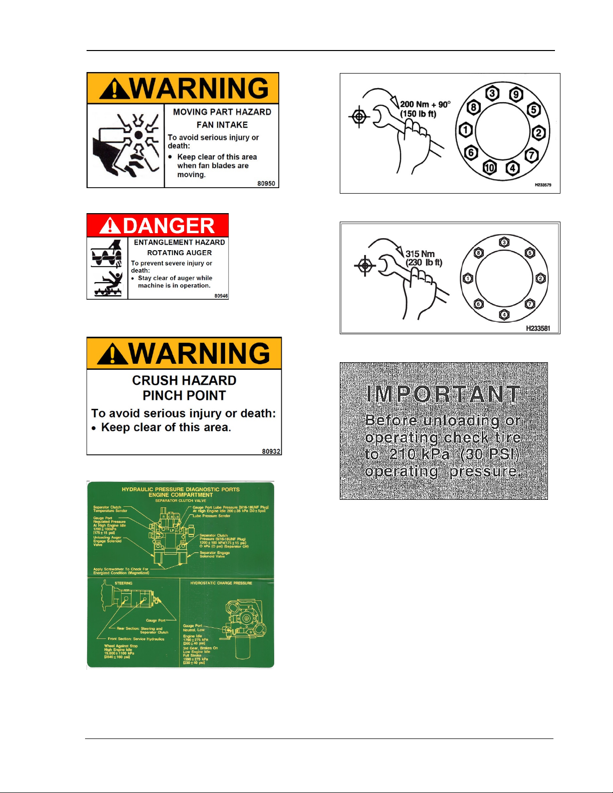
13 Decal # 80950
14 Decal #80946
15 Decal #80932
17 Decal #JH233579
18 Decal #JH233581
19 Decal #H140709
16 Decal #H128315
MAN141 09/16/15 19
Page 32

Safety 9980 Self-Propelled Peanut Combine
NOTES
20 09/16/15 MAN141
Page 33

9980 Self-Propelled Peanut Combine Operator’s Station
2.
Operator’s
Station
Cab Access ............................................. 22
Cab Ladder .......................................... 22
Cab Ladder Positions ........................... 33
Cab Landing Safety Chains .................. 34
Washing Cab Windows, Servicing
Headlights and Wiper ........................... 25
Emergency Exit .................................... 26
Fire Extinguisher .................................. 26
Right-Hand Side Cab Access ............... 26
Operator Controls .................................... 27
Comfort Command™ Operator’s Seat.. 28
Seat Operation ..................................... 29
Left-Hand Armrest and Seat Back ........ 30
Right-Hand Armrest Control Console ... 31
Seat Belts ............................................ 31
Steering Column .................................. 32
Gear Shift Lever ................................... 33
Manual Parking Brake .......................... 34
Brake Pedals ........................................ 34
Auxiliary Power Outlet Strip and Service
ADVISOR Diagnostic Connector .......... 35
Field Office Seat .................................. 36
Armrest Storage Box ............................ 36
Manual Storage .................................... 46
MAN141 09/04/15 21
Page 34
Operator’s Station 9980 Self-Propelled Peanut Combine
Cab Ladder
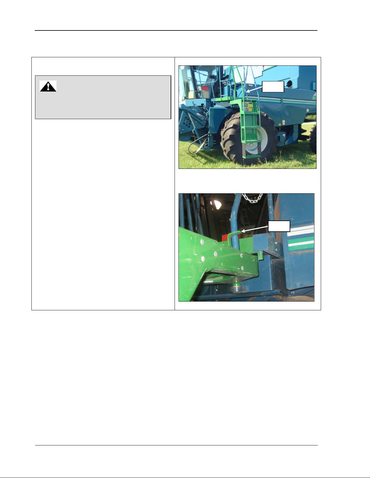
Ladder can be positioned from ground or
the ladder forward or rearward. The ladder
latch pin area. Do NOT use oil or grease in
CAUTION
Lever
Lever
Cab Access
landing or landing with lever (photos). S wing
locks into place (3 positions).
If the ladder latch appears loose, clean out the
this area.
Do NOT ride or attempt to climb front or
rear ladders while the machine is moving.
22 09/04/15 MAN141
Page 35
9980 Self-Propelled Peanut Combine Operator’s Station
Cab Ladder Positions
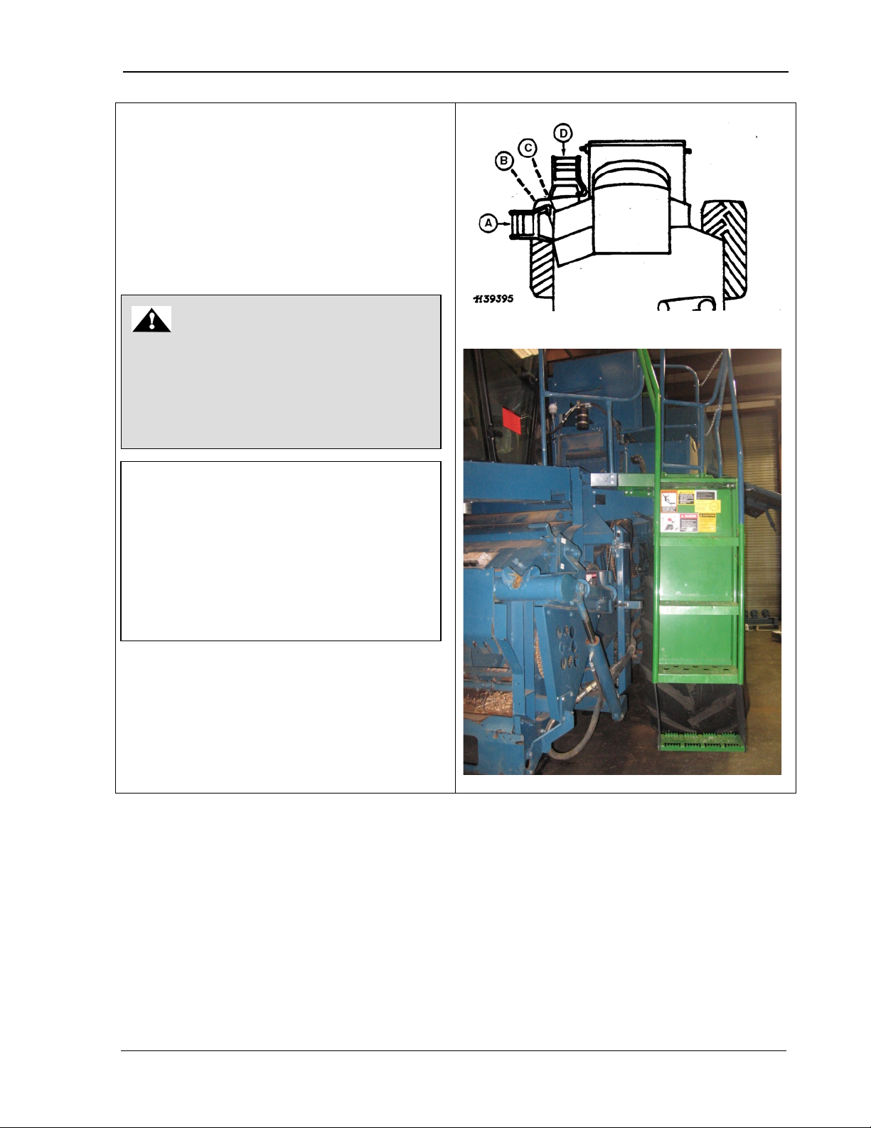
The sketch shows the different positions for
CAUTION
reduce the machine width and position
amber warning lamp toward oncoming
IMPORTANT! Long ladder extension
when the ladder is swung to position (D).
the cab ladder as follows:
A - normal operating field position
B - posit ion for a machine with a small header,
a ladder extension, or duals
C – driving position for long ladder extension
D – roadway driving position
Always swing ladder to position D before
transporting on public roadways in order to
motorists.
1390 mm (55 in) is required on machines
equipped with dual tires, axle spacers, etc.
will interfere with the platform drive shaft
Raising or lowering the feeder house could
damage a ladder, drive shaft, or drive shaft
shield. Place ladder in position (C) in this
situation.
MAN141 09/04/15 23
Page 36
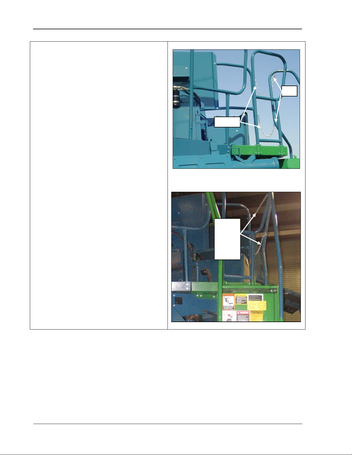
Operator’s Station 9980 Self-Propelled Peanut Combine
Cab Landing Safety Chains
ladder is in forward position (bottom photo).
Remove the pins and adjust the chains as
Chains
Pins
Tighten
ladder is
forward
Safety chains (top photo) must be tight when
needed.
chains
when
pulled
24 09/04/15 MAN141
Page 37
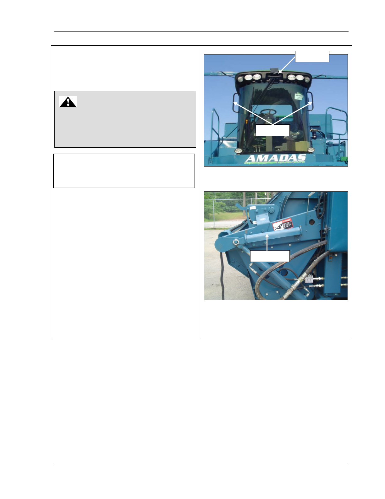
9980 Self-Propelled Peanut Combine Operator’s Station
Washing Cab Windows,
Use the ladder and landing to clean the left
Stand on the raised feeder house with
to clean front cab window and
For stability, use handrails on either side
Access the feeder house by stepping on
Handhold
Handrails
CAUTION
safety stop on feeder house life cylinder.
Close cab door securely and use
IMPORTANT! Do NOT manually move
Safety stop
Servicing Headlights and
Wiper
Raise feeder house completely and lower
handholds.
wiper arm, as this could cause damage to
the wiper mechanism.
side of the cab as follows:
•
feeder house safety stop lowered (bottom
photo)
service head lights or wiper.
•
of the cab and the handhold at the top of
the cab (photo).
•
the left-hand side.
• Use the step and landing to clean the rig ht
side of the cab.
MAN141 09/04/15 25
Page 38
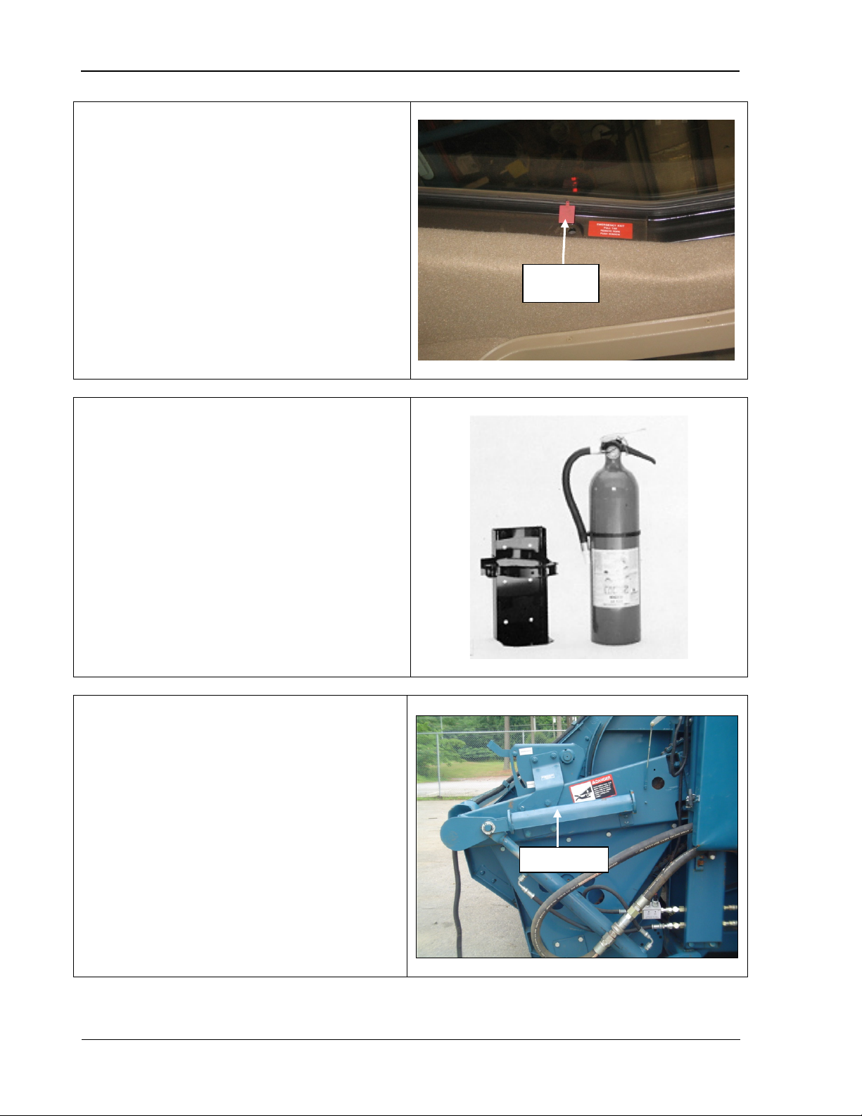
Operator’s Station 9980 Self-Propelled Peanut Combine
Emergency Exit
Pull the rubber rope from around the
dealer for
Fire Extinguisher
Read the label on the extinguisher and
Right-Hand Side Cab Access
Window
tab
Safety stop
If you ever need to exit the cab and cannot go
through the door:
1. Pull the tab indicated.
2.
window.
3. Push the window out and allow it to fall to
the ground.
See your AMADAS/John Deere
window replacement.
Although not supplied by AMADAS, it is highly
recommended that two rechargeable 10 lb.
ABC type dry chemical fire extinguishers be
installed on your combine.
become familiar with the instructions on how to
use and maintain it. Once the extinguisher is
discharged, no matter for how long, it must be
recharged.
Raise the feeder house and lower the feeder
house safety stop.
Use handhold, rails, and step to move around
cab.
26 09/04/15 MAN141
Page 39
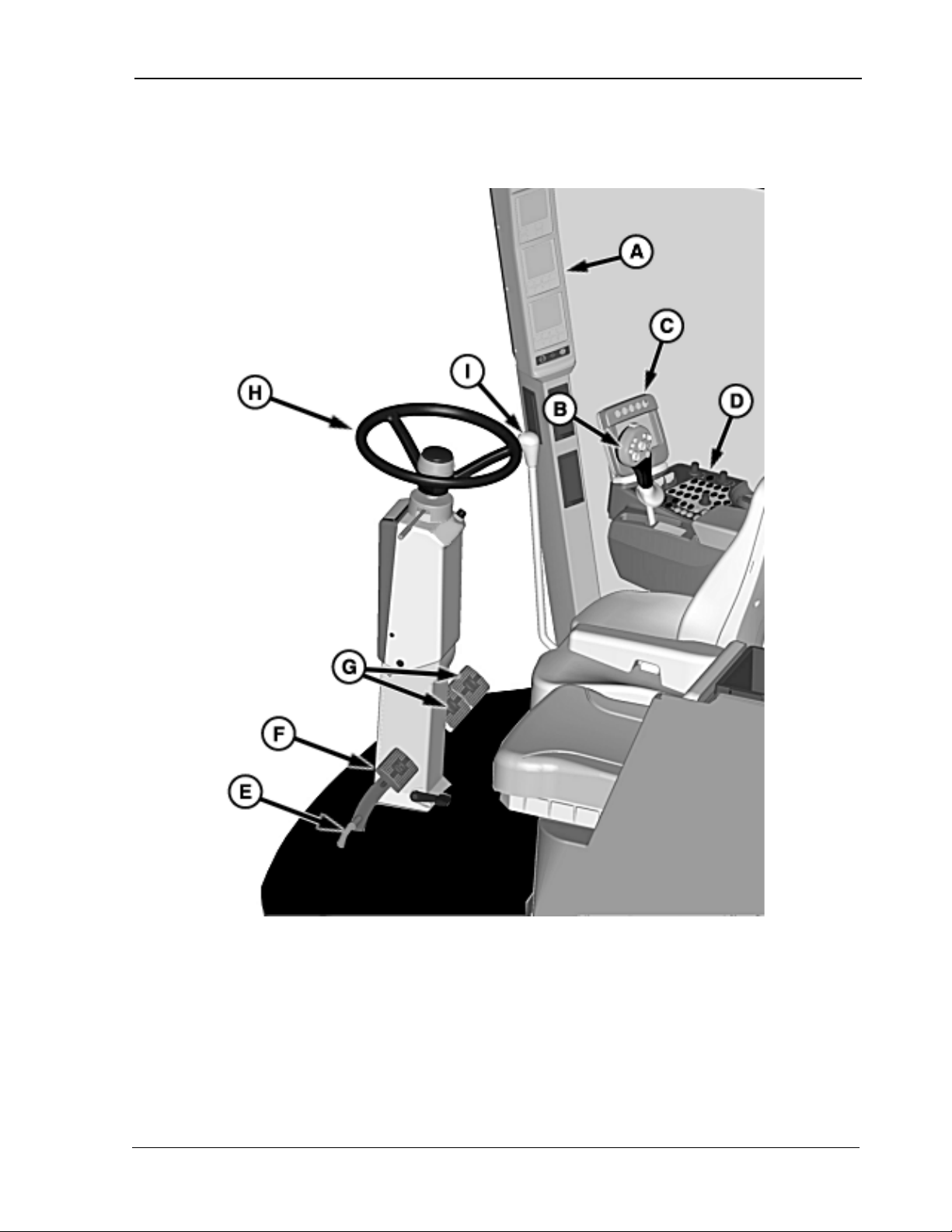
9980 Self-Propelled Peanut Combine Operator’s Station
A – CommandTouch TM Cab Cornerpost
E – Park Brake Dis engage Pedal
F – Park Brake Engage Pedal
Operator Controls
B – Multifunction Control Handle
C – Command Center Display
D – CommandTouch TM Armrest Console
MAN141 09/04/15 27
G – Brake Pedals
H – Steering Column
I – Gearshift Lever
Page 40
Operator’s Station 9980 Self-Propelled Peanut Combine
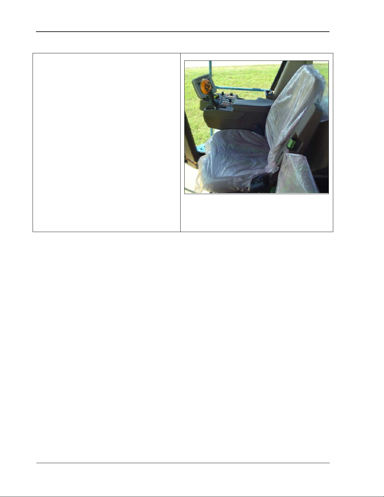
Comfort Command™
electric compressor to adjust the seat
suspension to match the operator’s height
Operator’s Seat
The Comfort Command™ operator’s seat has
an air suspension system for added operator
comfort. The seat has a self-contained
and weight.
The seat has four main adjustments:
• Vert ical shock damper
• Height adj ustment
• Fore/ aft adjustment
• Fore/ aft attenuator lock-out
• Seat bottom tilt
• Seat bottom fore/aft adjustment
• Seat back tilt
• Seat back lumbar support
• Left hand armrest.
28 09/04/15 MAN141
Page 41
9980 Self-Propelled Peanut Combine Operator’s Station
Seat Operation
the amount of “upward motion” the seat
Push the control forward for a softer ride or
medium firmness, move the control to the
raises or
or lowers the seat cushion for the best
locks out or releases forward or rearward
NOTE! Suspension can be adjusted to
reach limits in minimum and maximum
heights, which is effect locks out the
suspension system making it rigid.
Suspension height control will also hit
NOTE! If the seat does not float or “pump”
NOTE! The seat is equipped with an
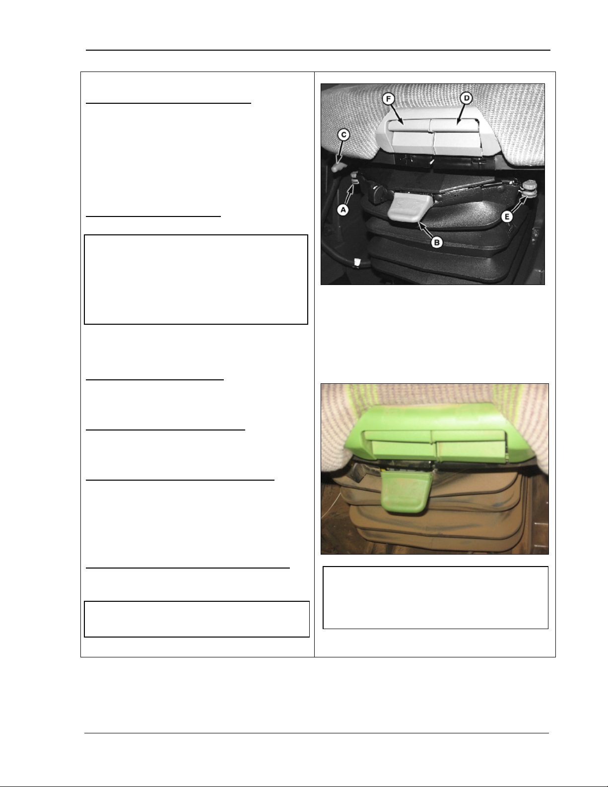
Vertical Shock Dampener Control (A) – limits
suspension provides.
move handle back for a firmer ride. For
middle.
Height Adjustment Handle (B) –
lowers the seat.
limits if adjusted too close to the extremes.
To raise the seat, pull up on the handle. To
lower the seat, push down on the handle.
Fore/Aft Adjustment Handle (C) – slides the
seat forward or rearward for the best working
position.
Seat Bottom Tilt Control Handle (D) – raises
A – Vertical Shock Dampener Control
B – Height Adjustment Handle
C – Fore/Aft Adjustment Handle
D – Seat Bottom Tilt Control Handle
E – Fore/Aft Attenuator Lock-Out Handle
F – Seat Bottom Fore/Aft Adjustment Handle
working position.
Fore/Aft Attenuator Lock-Out Handle (E) –
movements.
Pull up on the handle to lock or push down on
the handle to release.
Seat Bottom Fore/Aft Adjustment Handle (F)
– moves the seat bottom forward or rearward
for the best working position.
up, see your AMADAS/John Deere Dealer.
MAN141 09/04/15 29
operator’s presence system. The machine
shuts off automatically when the operator
leaves the seat.
Page 42
Operator’s Station 9980 Self-Propelled Peanut Combine
Left-Hand Armrest and Seat
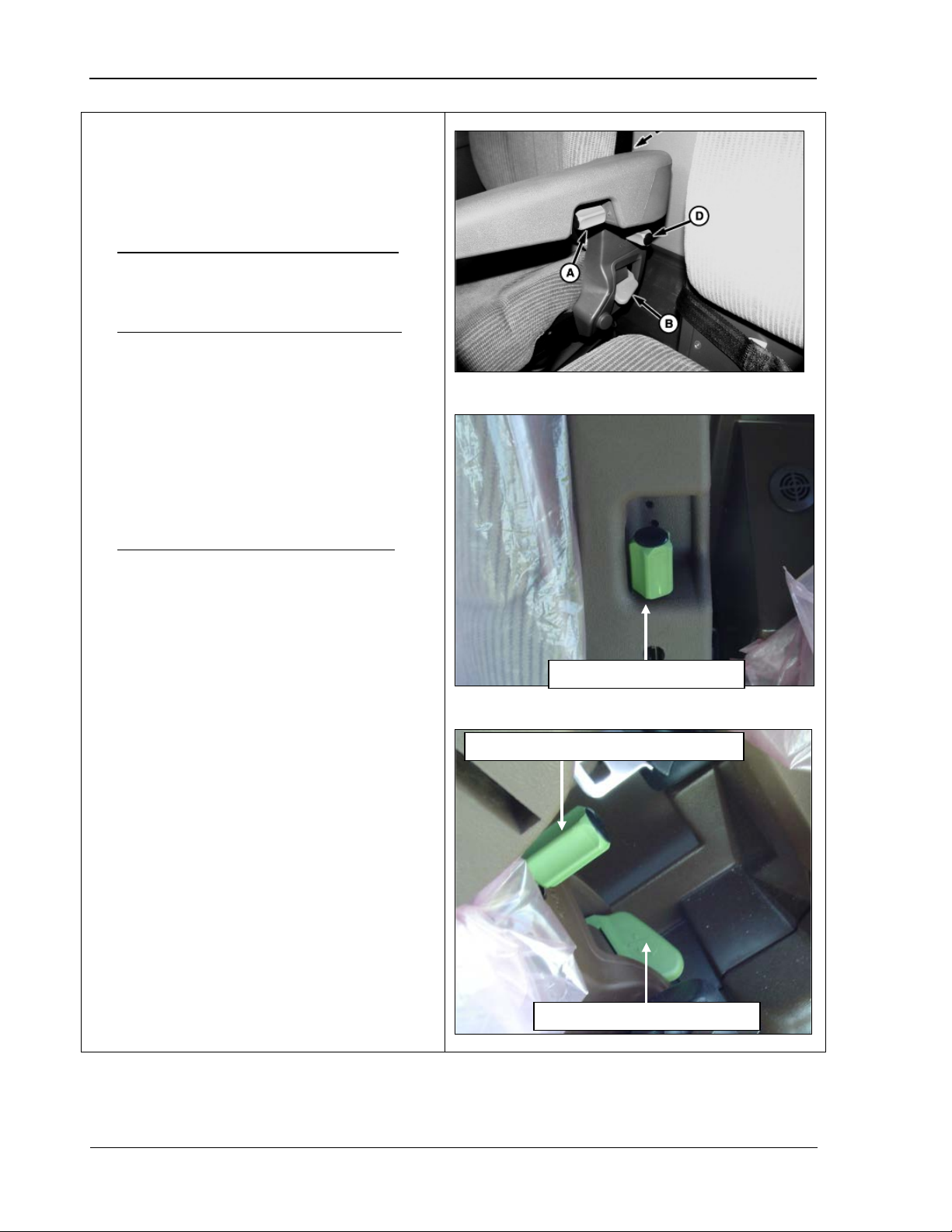
Make adjustments to the armrest and seat
: to
lower the armrest, turn knob clockwise.
: to
Turn the knob counterclockwise to
Adjust the armrest to the desired
Armrest angle adjust knob
Left-hand armrest vertical adjust knob
Seat back angle adjust handle
Back
back position as follows:
• (A) Left armrest angle adjust knob
To raise, turn counter clockwise.
• (B) Left armrest vertical adjust knob
set armrest at desired height:
1.
loosen.
2.
height.
3. Turn the knob clockwise to re-tighten.
• (C) Seat back angle adjust handle: To
change the position of the seat back, pull
the handle up and release when the seat
is in the correct position.
30 09/04/15 MAN141
Page 43
9980 Self-Propelled Peanut Combine Operator’s Station
Right-Hand Armrest Control
in the slots on the outer plate until in
position.
Seat Belts
Seat belts are standard equipment on both
operator and instructional seats. Lap type
seat belts have a push button quick release
matic belt retraction to allow
CAUTION
including the
mounting hardware, buckle, belt, or
as cuts, fraying, extreme or unusually
seat belt system should be replaced
approved for your machine. See your
Console
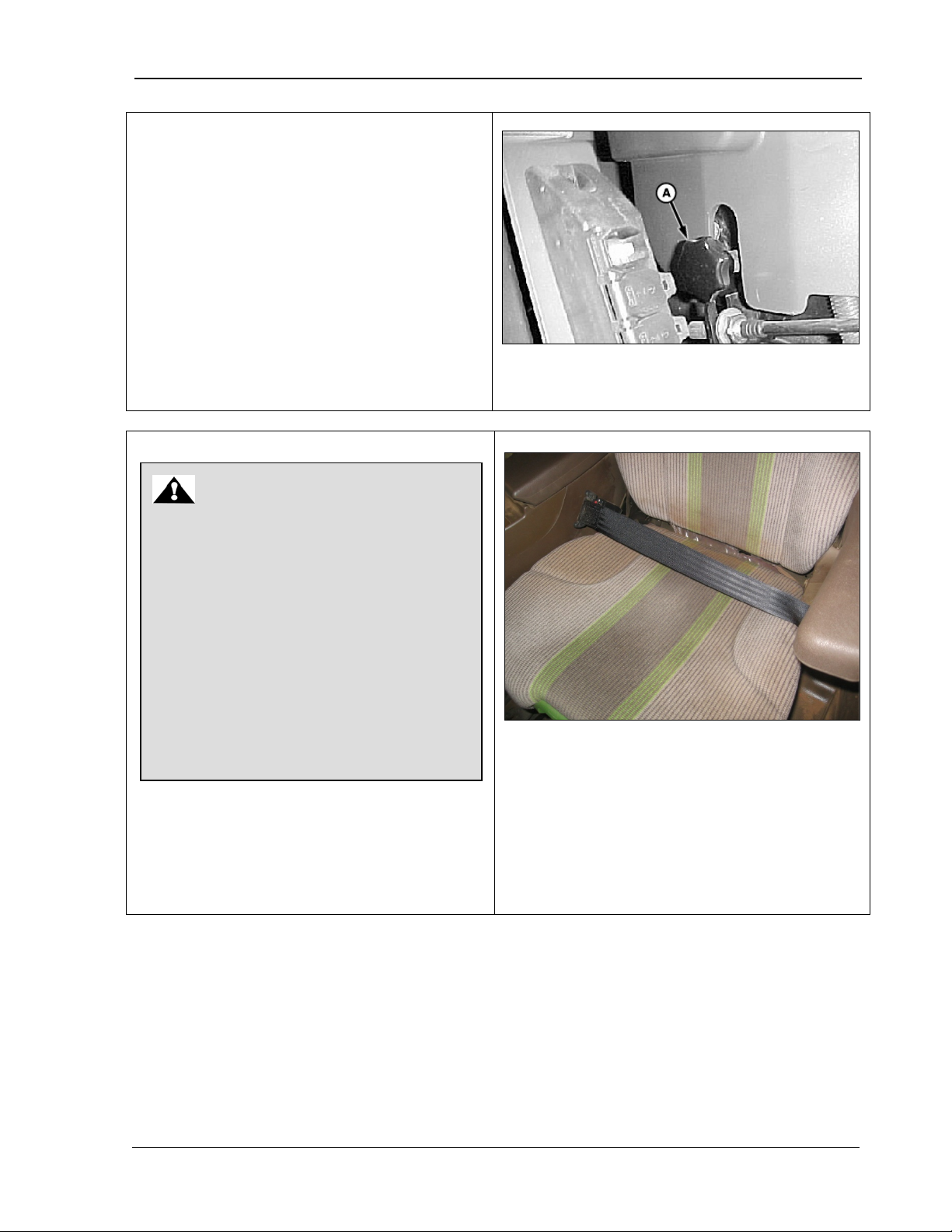
The knob on the right side of the operator’s
seat (A) allows you to adjust the right-hand
armrest control console. To adjust:
1. Loosen the knob.
2. Slide the armrest up/forward or down/back
desired position.
3. Tighten the knob to lock the armrest into
Inspect seat belts and mounting hardware
on your machine at least once a year. If
the seat belt system,
retractor, shows any sign of damage such
wear, discoloration or abrasion, the entire
immediately. For your safety, replace the
belt system only with replacement parts
AMADAS/John Deere dealer.
A – Armrest control knob
and auto
unrestricted exiting and entering.
MAN141 09/04/15 31
Page 44
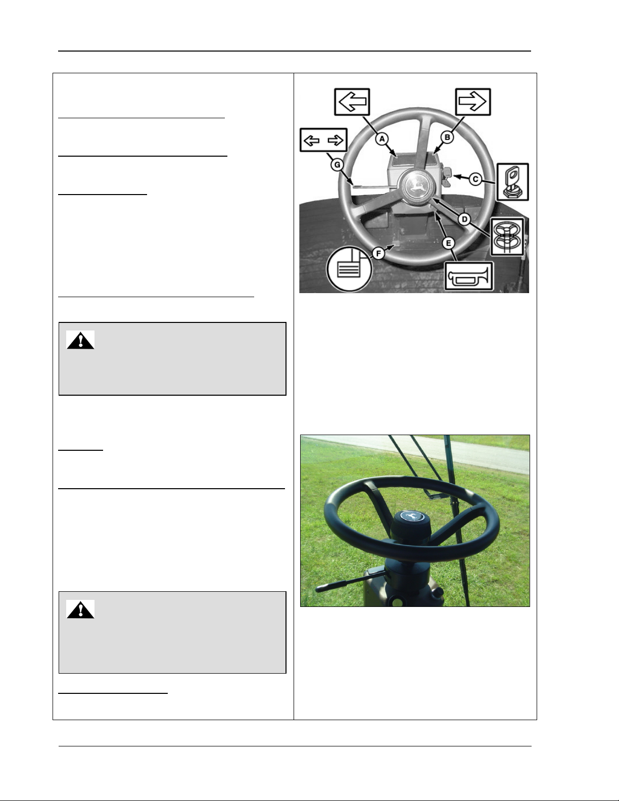
Operator’s Station 9980 Self-Propelled Peanut Combine
Steering Column
: used to warn bystanders to stay
:
used to move the steering column with the
Press the pedal to release the lock on the
steering column and move the column to the
CAUTION
CAUTION
(A) Left turn signal indicator light: shows the
operator that a left turn is planned.
(B) Right turn signal indicator light: shows t he
operator a right turn is planned.
(C) Starter Switch: allows the key switch to be
turned to:
First position – OFF
Second position – Accessories
Third position – Run
Fourth position – Start
(D) Steering column vertical adjustment: used
to adjust the steering column up or down.
Loosen the hub and push or pull the wheel to
position. Slightly tighten the hub to hold
(E) Horn
clear.
(F) Steering column horizontal adjustment
Adjust the steering wheel only when the
machine is stopped.
A – Left turn signal indicator
B – Right turn signal indicator
C – Starter switch
D – Steering column vertical adjustment
E – Horn
F – Steering column horizontal adjustment
G – Turn signal switch
pedal to the desired location.
desired position. The column locks into place
when the pedal is released.
(G) Turn signal switch: used to indicate a leftor right-hand turn.
Adjust the column only when the machine
is stopped. Do NOT step on the pedal
without holding the steering wheel.
32 09/04/15 MAN141
Page 45
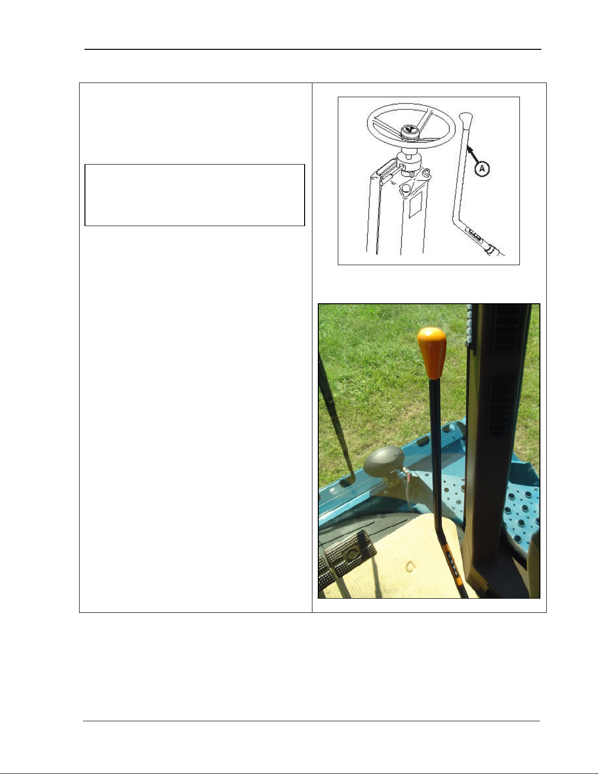
9980 Self-Propelled Peanut Combine Operator’s Station
Gear Shift Lever
IMPORTANT! Stop the combine and
The gear shift lever (A) shifts in a straight line
pattern with detents for gears 1, 2, and 3. A
lesser detent is felt for neutral between 1
nd
2
gears.
move the hydro lever (multi-function
handle) to neutral before shifting from one
gear to another.
st
and
A – Gear shift
MAN141 09/04/15 33
Page 46
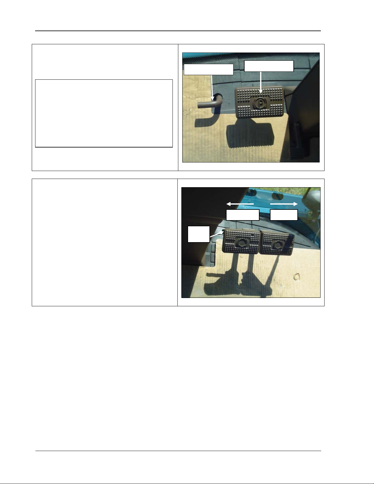
Operator’s Station 9980 Self-Propelled Peanut Combine
Manual Parking Brake
IMPORTANT! The combine is equipped
pedals. Make sure you engage the
the combine with the engine turned off
Brake release
Parking brake
Brake
lock
Unlocked
Locked
To engage the parking brake, press the pedal.
To release the brake, pull the handle.
with manual engage and disengage brake
parking brake when the engine is running
and the combine is parked. NEVER leave
without engaging th e parking brake.
Brake Pedals
The combine has two brake pedals. For field
use, leave the brake pedals unlocked. If you
are transporting the combine, lock the pedals
together. The photo shows the brake pedals
with the brake lock in the unlocked position.
34 09/04/15 MAN141
Page 47
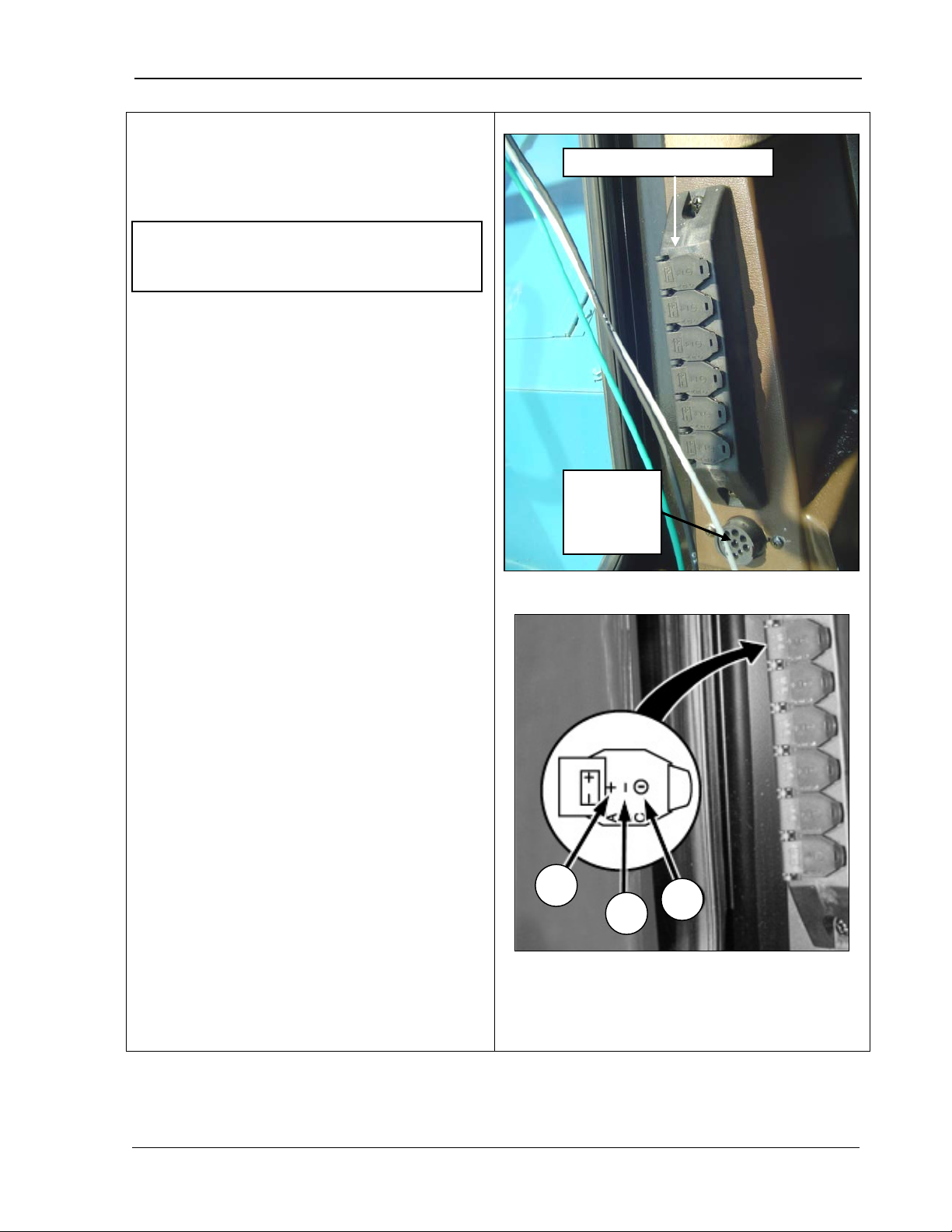
9980 Self-Propelled Peanut Combine Operator’s Station
Auxiliary Power Outlet Strip
equipped with six additional electrical outlets,
switched
The service ADVISOR diagnostic connector
onnect a laptop
, when the key switch is
NOTE! The maximum combined current
C B A
Auxiliary power outlet strip
Service
and Service ADVISOR
Diagnostic Connector
draw for all outlets is 30 AMPS.
The auxiliary power outlet strip (top photo) is
which are located at lower rear of right-hand
window. These outlets provide keyor unswitched power.
provides the ability to c
computer to diagnose the machine if needed.
The spade terminals of the outlet strip are as
follows:
A – Direct positive power, on at all times.
B – Ground
C – Auxiliary power
ON.
ADVISOR
diagnostic
connector
MAN141 09/04/15 35
A – Direct positive power
B – Ground
C – Auxiliary power
Page 48
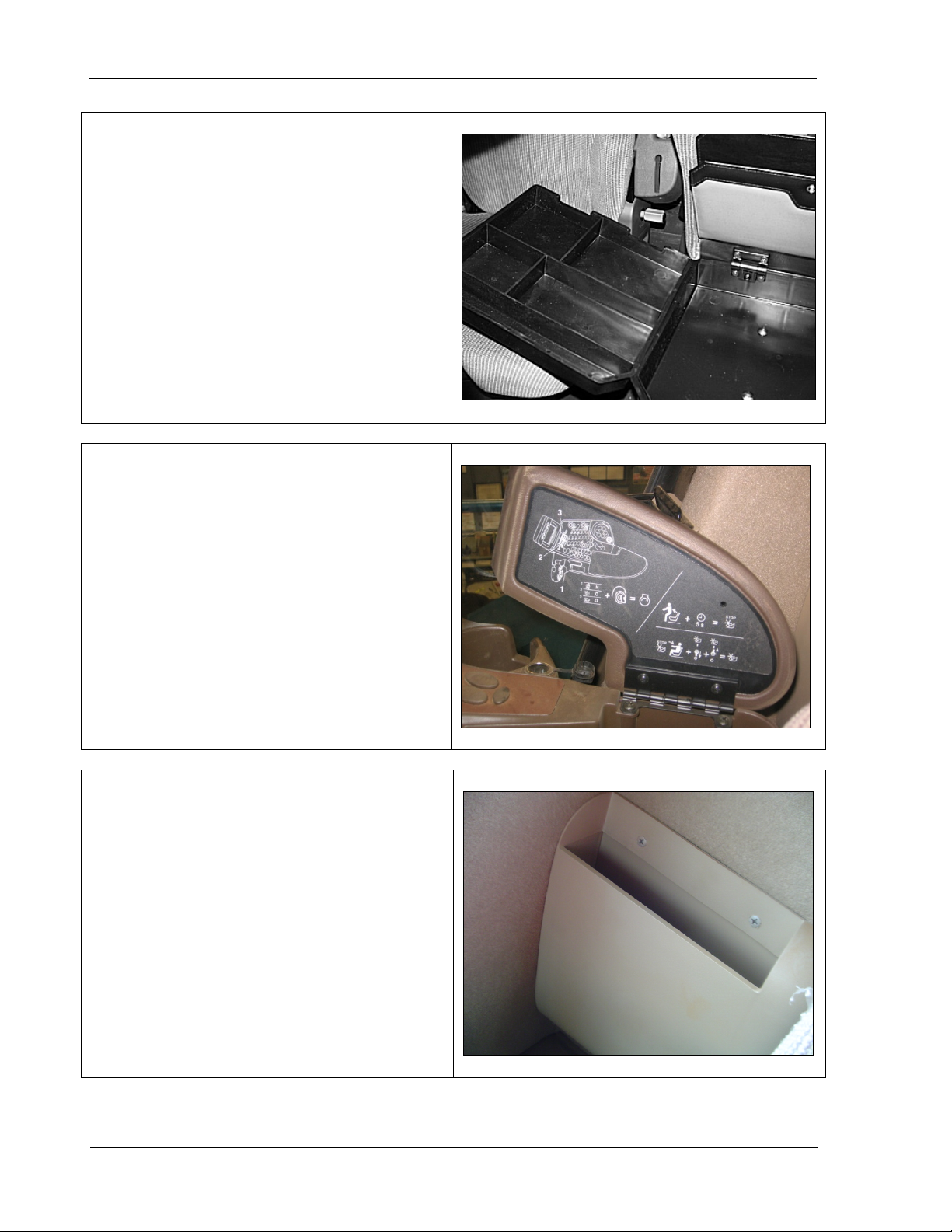
Operator’s Station 9980 Self-Propelled Peanut Combine
Field Office Seat
cassettes, CDs and cell phones.
Armrest Storage Box
the lid provides information for starting your
Manual Storage
The instructional or Field Office seat contains
storage folders and a removable tray for items
such as
When the tray is removed, the compartment is
sized to hold a laptop computer.
The armrest lid lifts for storage. The decal on
machine.
Keep your manuals in the holder at the rear of
the seat.
36 09/04/15 MAN141
Page 49

9980 Self-Propelled Peanut Combine Operator’s Controls
3.
Operator’s
Controls
G
eneral Overview .................................... 38
CommandTouch Armrest Console ........... 39
Header Engage/Header Reverse ......... 40
Separator Engage ................................ 42
Header Height Control ......................... 43
Road Transport Disconnect .................. 43
Engine Speed ...................................... 44
10% Engine Speed Control .................. 44
Four-Wheel Drive (Optional) ................ 45
Operator Interface Controls .................. 46
Set Point Modes (Manual or Automatic) 47
Manual Mode .................................... 48
Feeder House Rate/Sensitivity Adjust .. 49
Header Speed ...................................... 50
Cleaning Fan Damper .......................... 51
Threshing Speed .................................. 52
Elevator Fan Damper Speed ................ 53
Multifunction Handle ................................ 54
Multifunction Handle Use ..................... 55
Quick Stop Switch ................................ 56
Header Height Activation Buttons ......... 57
Bin Lift .................................................. 58
Header Lift Switch ................................ 59
Conveyor Swing Switch ....................... 60
Unloading Conveyor Drive Button ........ 61
Peanut Door Alarm............................... 62
MAN141.rev1 08/05/16 37
Page 50
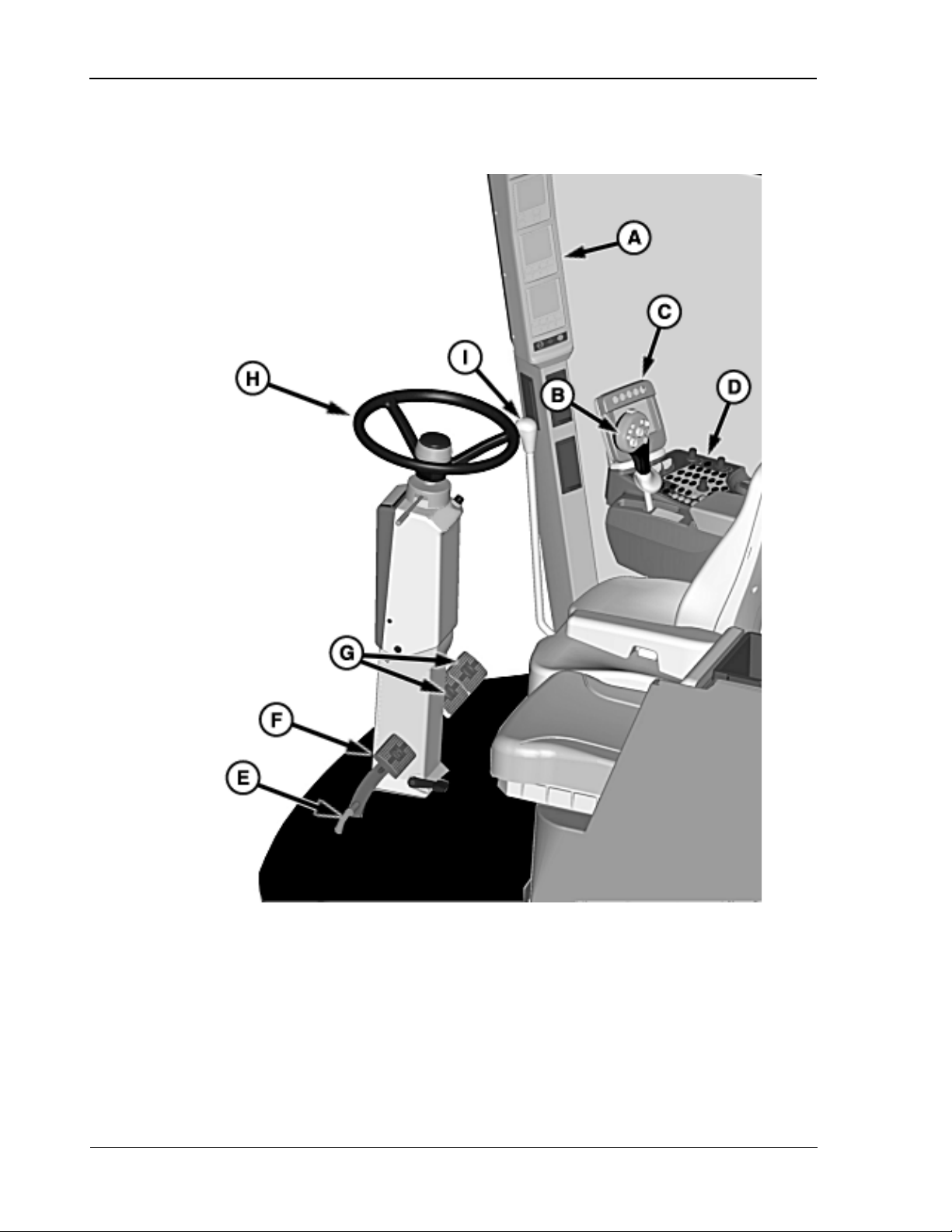
Operator’s Controls 9980 Self-Propelled Peanut Combine
A – CommandTouch TM Cab Cornerpost
E – Park Brake Dis engage Pedal
F – Park Brake Engage Pedal
General Overview
B – Multifunction Control Handle
C – Command Center Display
D – CommandTouch TM Armrest Console
G – Brake Pedals
H – Steering Column
I – Gearshift Lever
38 08/05/16 MAN141.rev1
Page 51
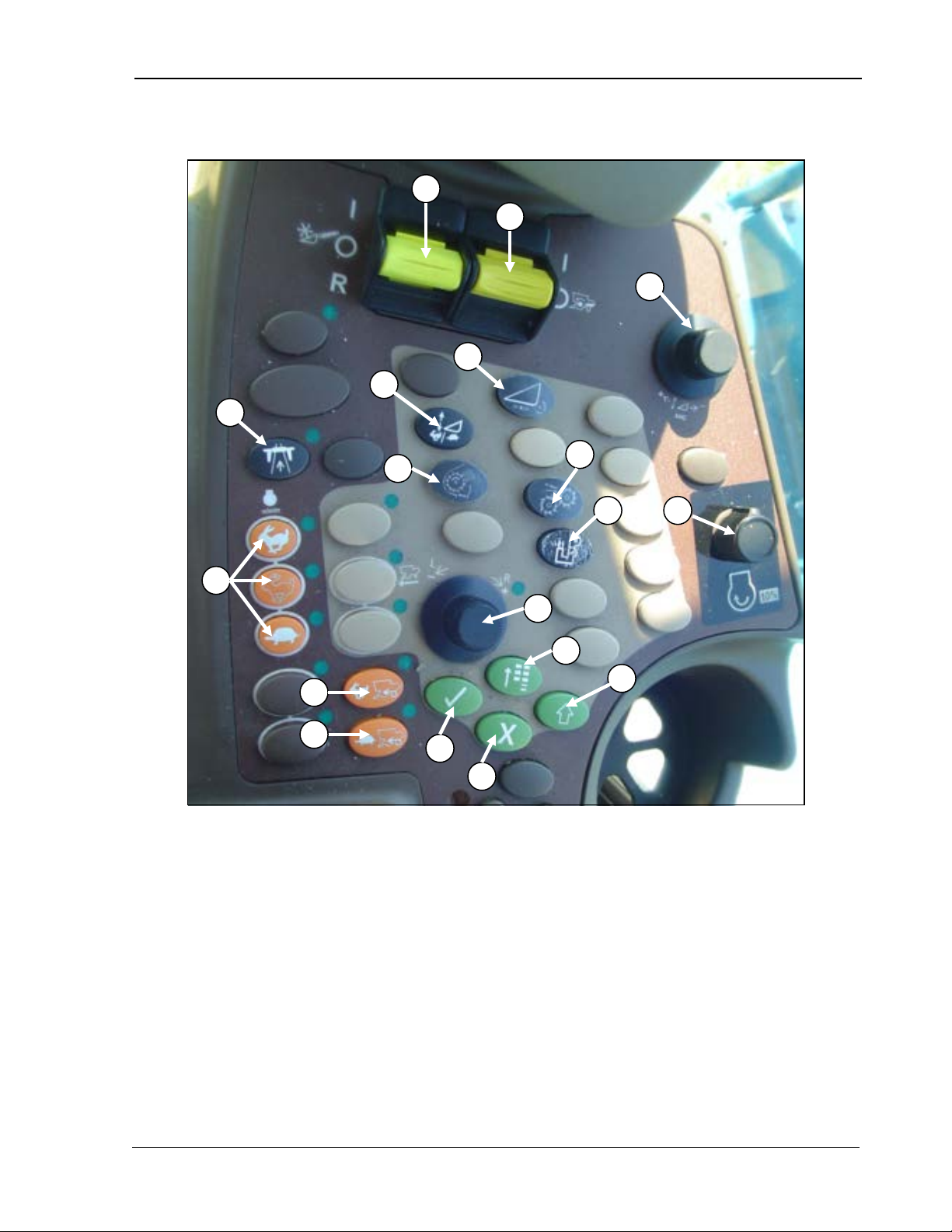
9980 Self-Propelled Peanut Combine Operator’s Controls
A – Header Engage
J – Elevator Fan Damper Position
A B C D E
F
G
H
I J K
L
M
P
O NQ
R
CommandTouch Armrest Console
B – Separator Engage
C – Automatic Header Height Control
D – Road Transport Disconnect
E – Feeder House Rate/Sensitivity Adjust
F – Header Speed
G – Engine Speed
H – Cleaning Fan Damper Position
I – Threshing Speed
MAN141.rev1 08/05/16 39
K – 10% Engine Speed control
L – Selection Dial
M – 4-Wheel Drive High Speed
N – 4-Wheel Drive Low Speed
O – Confirm
P – Cancel
Q – Main Menu
R - Select
Page 52
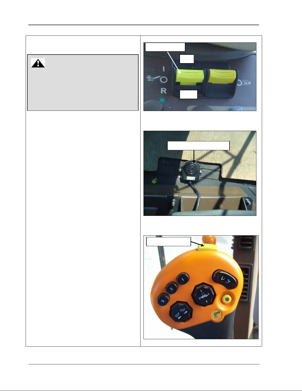
Operator’s Controls 9980 Self-Propelled Peanut Combine
Header Engage/Header
The header engage switch controls the
and functions as
eader must be
connections made for the header to
For normal field operation, push the
header engage switch forward until it
. This will start the
up in a feeding
If the header reverse foot switch is
to the OFF position. It can also be
with the quick stop switch
located on the top of the control handle
(bottom photo). To restart the header
ON
Off
Header engage
Header reverse foot switch
Quick stop switch
WARNING
Never attempt to engage the header
hoses either connected to a header or
connected to each other in a “loop.”
Attempts to do so could damage the
Reverse
header auger and pickup
follows:
• A properly equipped h
switch without the header hydraulic power
header hydraulic power system.
installed with both hydraulic and electrical
operate. The separator must also be on
for the header to function.
•
latches (top photo)
header auger and pickdirection, unless the header reverse foot
switch (middle photo) is pressed.
•
pressed while the header is engaged, the
pickup will stop and the header auger will
run in the direction opposite of feeding.
• The header can be stopped by pressing
the header engage switch and moving it
stopped
after using this switch, move the header
engage switch first to OFF and then back
to ON.
40 08/05/16 MAN141.rev1
Page 53
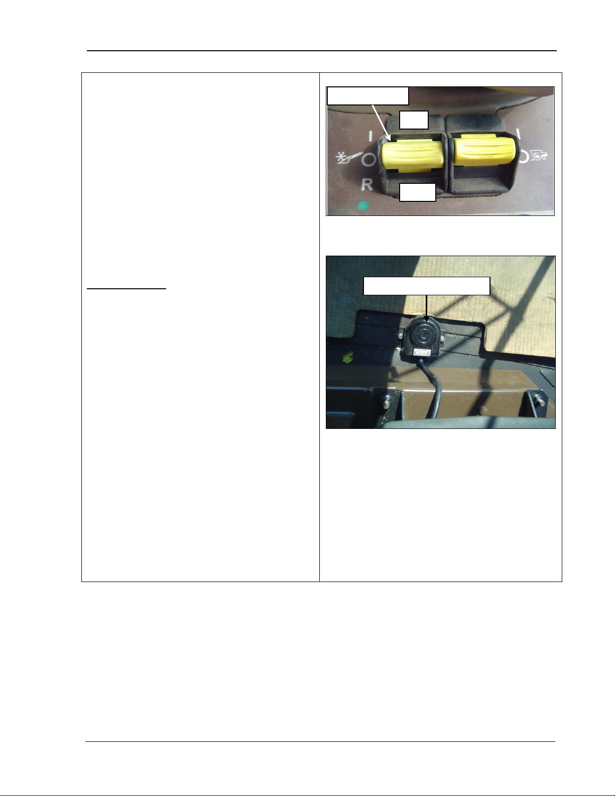
9980 Self-Propelled Peanut Combine Operator’s Controls
Header Engage/Header Reverse
The operator must be seated to operate
header is engaged, it will continue to
operate for five seconds before it
engage, sit in the seat, and turn
If the header fails to engage or stops
is controlled by the header
header auger in reverse and free any
Release the switch as soon as the “plug”
is backed out. The header will return to
Allow the feeder house to clear the “plug”
Resume harvesting. Do NOT attempt to
force “plugs” through by repeated cycling
of reversing drive. Repeated cycling
shortens the life of components. If a
“plug” will not clear with one or two
ry to manually
ON
Off
Header engage
Header reverse foot switch
•
the header.
o If the operator leaves the seat after the
disengages.
o T o re-
the switch off and then back on.
o
suddenly, sit squarely on the seat, turn
the switch off, and then turn back on to
re-engage.
Header reverse
reverse foot switch. To unplug the header:
1. Stop the forward motion of the combine.
2. Press the header reverse switch to run the
“plug.”
3.
feeding rotation.
4.
material before continuing forward.
5.
reverses, it will be necessa
remove it as described on the next page.
MAN141.rev1 08/05/16 41
Page 54
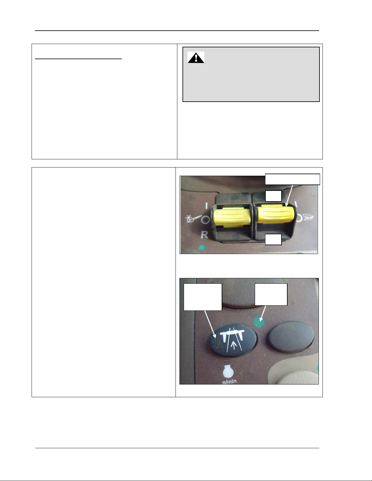
Operator’s Controls 9980 Self-Propelled Peanut Combine
Header Engage/Header Reverse
Bring the header engage and separator
Place the hydrostatic handle to
Turn the combine ignition switch to the
The separator engage switch turns on the
Push up to turn ON; pull down to turn
be in field position to turn the separator
(the indicator light
speed and cleaning fan
The separator should only be engaged at
When the combine is run at high idle, the
disengaged after the
WARNING
running! Serious injury or death may
Off
On
Road
Separator engage
Indicator
To manually remove a “plug”:
1.
engage switches to the “OFF” position.
2.
“NEUTRAL” and set the parking brake.
3.
“OFF” position and remove the key.
4. Follow all safety warnings in Chapter 1
Safety, and safely remove the plug.
Separator Engage
separator.
•
OFF.
• T he road transport disconnect switch must
NEVER manually remove a “plug” from the
combine header with the combine engine
occur.
engage switch to ON
must be OFF).
• Separator drive
speed adjust systems only work when the
separator is running.
• T his switch must be off to start the engine.
•
low idle speed.
•
separator should be
engine is brought down to mid idle.
transport
disconnect
light
42 08/05/16 MAN141.rev1
Page 55
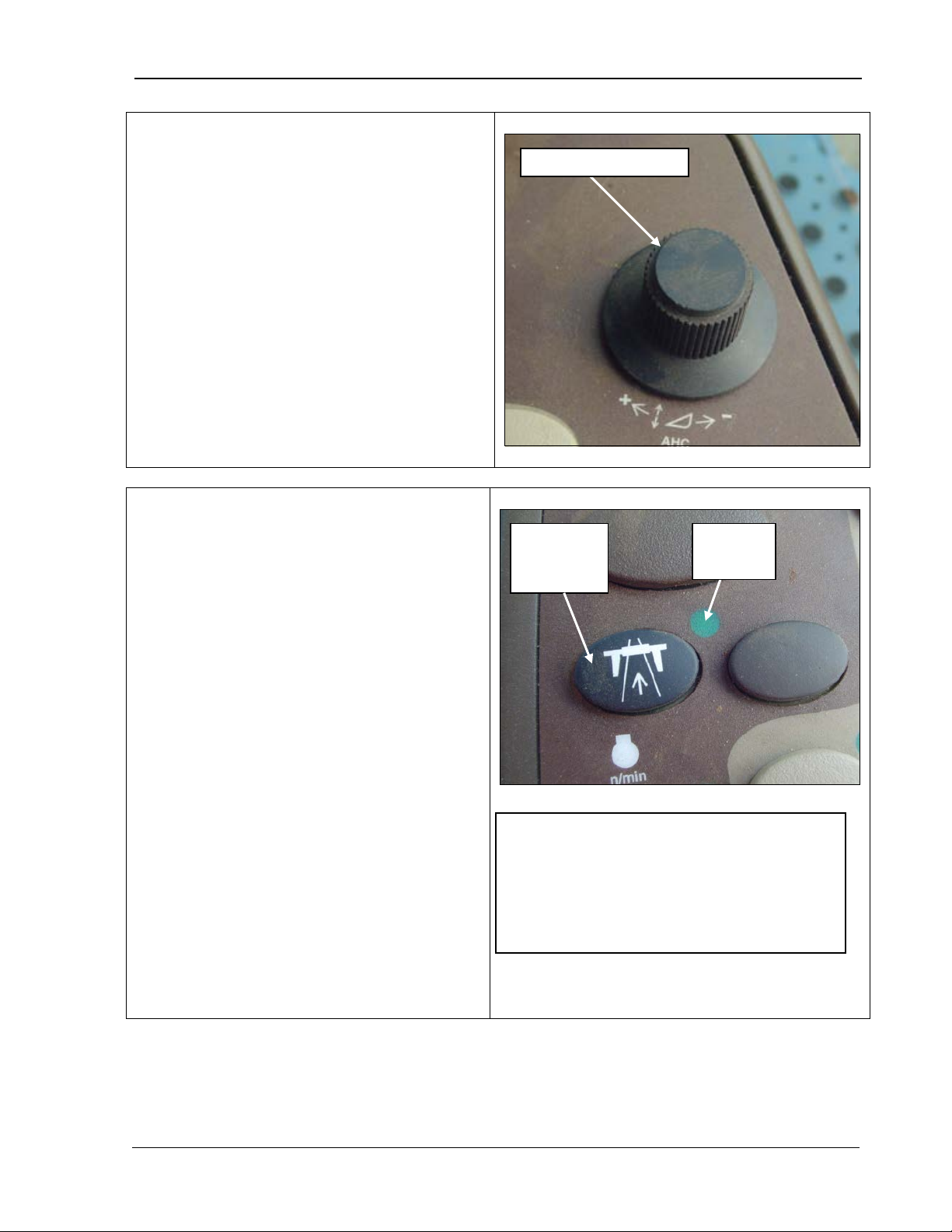
9980 Self-Propelled Peanut Combine Operator’s Controls
Header Height Control
ground and return to that position
point for
esume and Header Height
Header Height
) to
in road position when you transport the
vents the following
ready for field operations, press the road
, until the indicator light turns OFF.
The above functions will be operational
NOTE! The machine will not enter road
mode if the separator is engaged. A
warning alarm screen will appear
Header height control
Road
Indicator
The header height control switch allows you to
select the position of the header relative to the
automatically. It controls the set
Header Height R
Sensing. See the sections “
Resume” and “Header Height Sensing” in
Chapter 5, CommandTouch Cornerpost.
Turn the dial towards the plus sign (+) to raise
the header and set point, or towards (lower the header and set point.
Road Transport Disconnect
The road transport disconnect switch must be
machine on the roadway.
When the road transport disconnect switch is
pressed, the indicator light turns ON, showing
the switch is in road position. When on, the
road transport switch pre
functions:
• Header height resume
• Header height sensing
• Unloading conveyor
• Header raise/lower
• Separat or engage
• Header engage
• Basket raise/lower
After the machine is transported and you are
transport disconnect switch and hold for two
seconds
again.
transport
disconnect
light
indicating the separator is engaged. Shut
the separator OFF to engage the road
transport switch.
MAN141.rev1 08/05/16 43
Page 56
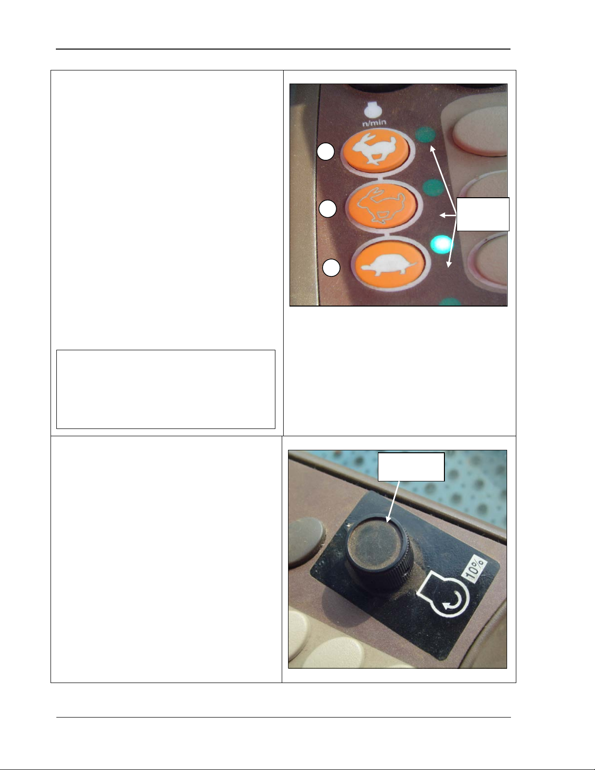
Operator’s Controls 9980 Self-Propelled Peanut Combine
Engine Speed
switch when it is pressed. If you press the
10% Engine Speed Control
engine speed up to 10% when it is in fast idle.
To reduce engine speed, turn the knob
IMPORTANT! Whenever the combine is
being moved, the engine should be in
so can cause severe damage to the
C B A
Indicator
10% Engine
speed control
The engine speed switches control the engine
RPM. Control engine speed as follows:
• For fast idle (234 0 R PM*), press switch A.
*w/out Separator engaged**
**w/Separator engaged (2200 RPM –
adjustable to 1950)
[See 10% Engine Speed Control
section]
• For mid id le (1690 RPM), press switch B.
• For slow idle (1200 RPM), press switch C.
Note that an indicator signal lights up beside a
switch again, the light goes out and the engine
is taken out of that idle speed.
either the mid or high speed. Failure to do
hydrostat system.
lights
A – Fast speed
B – Medium
C – Slow
The 10% engine speed control switch reduces
counterclockwise.
Note: The 10% engine speed control only
functions while harvesting [i.e.: separator
engaged.]
When separator is disengaged, engine high
idle speed will return to 2340.
When separator is reengaged, it will return to
previously set RPM.
44 08/05/16 MAN141.rev1
Page 57
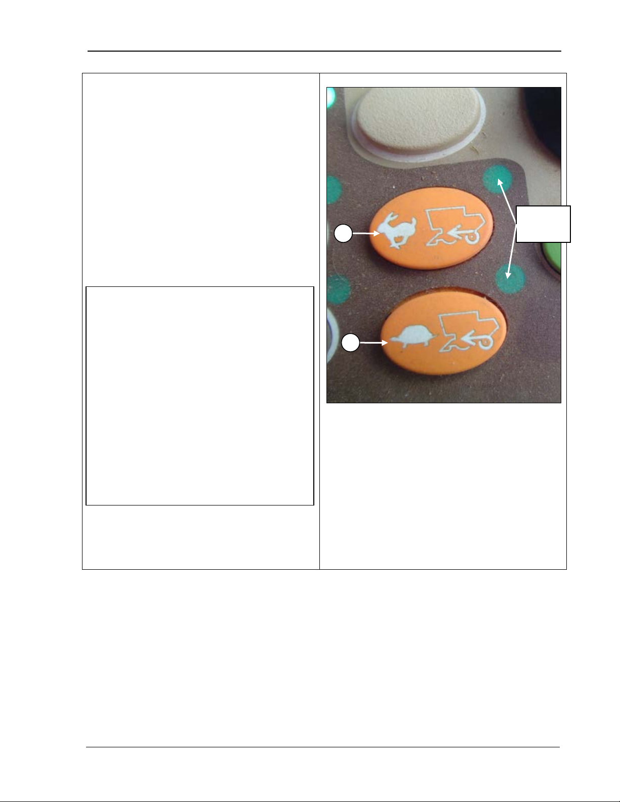
9980 Self-Propelled Peanut Combine Operator’s Controls
Four-Wheel Drive (Optional)
(A) and (B)
corresponding indicator light comes on
Press the turtle button (B) to use when
You can switch between the two buttons
, for
Indicator
A
B
IMPORTANT! Remember the following:
machine at maximum travel speed.
Reduce the speed to half of the
wheel drive OFF before
hydrostatic system and the machine
control handle to neutral and shift
The four-wheel drive buttons
control the four-wheel drive system.
• Press the rabbit button (A) to use 4-wheel
drive with higher speeds. Note that the
when either switch is pressed and fourwheel drive is activated.
•
more traction is needed.
•
while harvesting.
• T o prevent damage, do NOT switch 4wheel drive ON or OFF while driving
the
maximum speed.
• Turn the 4going down steep grades.
• In condit ions t hat cause pressure in the
slows or stops, move the multifunction
transmission to a lower gear.
Refer to Chapter 12, Transportation
specific information on using the Four-Wheel
Drive option.
lights
A – High idle 4-wheel drive
B – Low idle 4-wheel drive
MAN141.rev1 08/05/16 45
Page 58
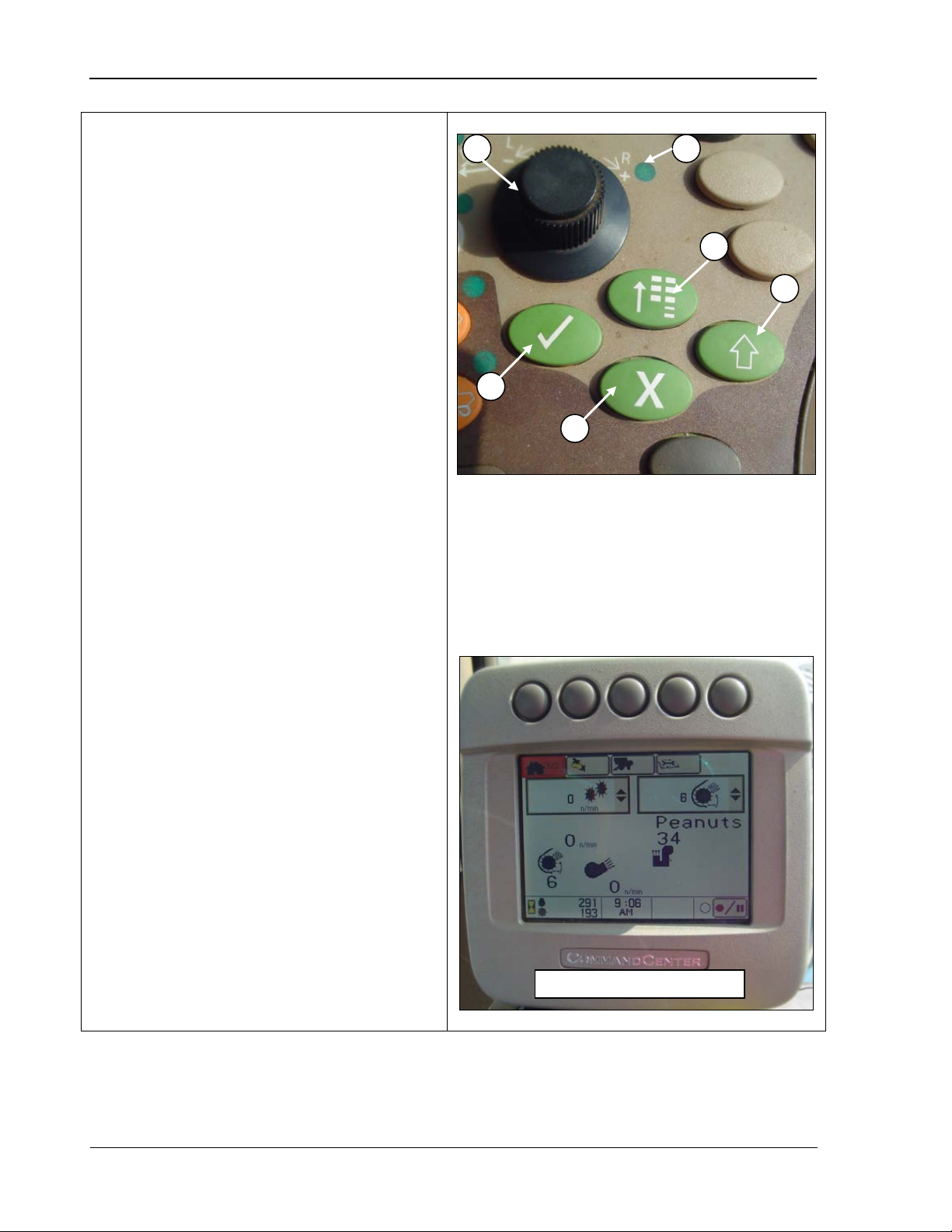
Operator’s Controls 9980 Self-Propelled Peanut Combine
Operator Interface Controls
each item on the CommandCenter
display. As each item is highlighted, a
“tool tip” appears describing what the
also used for data
entry to increase/decrease numeric
(C): allows you to select the
highlighted area on the CommandCenter
display or to confirm an action (such as
nge the
active “application” that the
CommandCenter display is running.
(E): allows you to cancel any
which display the selection dial controls
A C D E F
B
CommandCenter main menu
• Selection Dial (A): allows you to select
highlighted object is.
The selection dial is
values. The indicator turns ON when you
press a switch that can be adjusted using
the selection dial.
• Indi cator Light (B): shows that a switch
was selected and can now be adjusted to
your desired setting.
• Confirm
adjusting a speed).
• Main Menu (D): used to cha
Items or applications on the menu include:
o Combine settings
o Onboard diagnostic troubleshooting
o Disp lay settings
• Cancel
action on the CommandCenter display at
any time.
+
• Displ ay Select (F) : allows you to change
A – Selection dial
B – Indicator light
C – Confirm
D – Main menu
E – Cancel
F – Display select
(CommandCenter or GreenStar display, if
equipped).
46 08/05/16 MAN141.rev1
Page 59
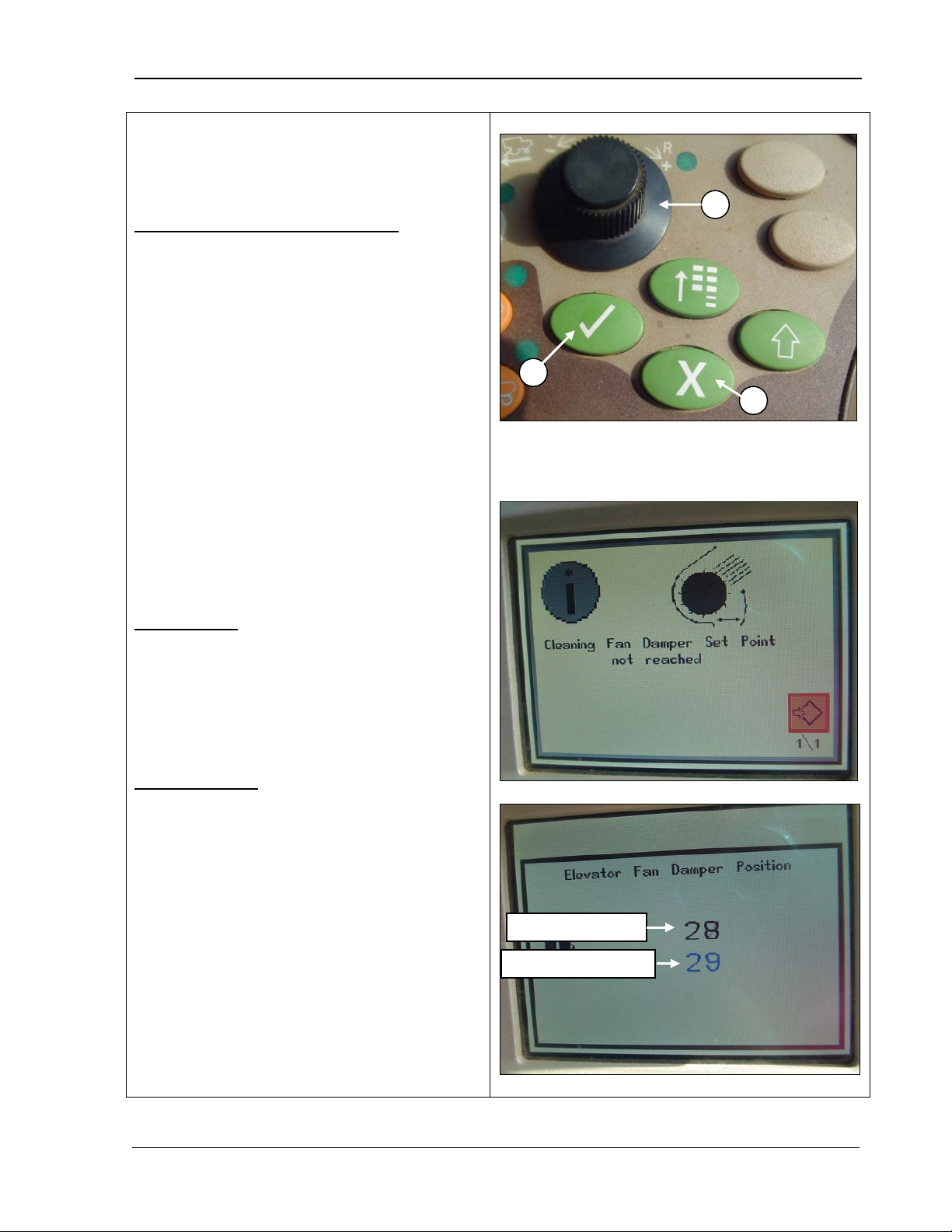
9980 Self-Propelled Peanut Combine Operator’s Controls
Set Point Modes (Manual or
, the
When the set point screen displays, the
the CommandCenter, press Confirm (B)
Pressing Confirm (B) while adjusting
Pressing Cancel (C) while adjusting
system continues adjusting in the
Pressing Cancel (C) while adjusting
A B C
Current set point
Value being changed
Automatic)
Set point modes function as follow:
Both manual and automatic modes:
• W hen you turn the selection dial (A)
set point is either increased (toward +) or
decreased (toward -).
• If you select a set point that is outside of
machine range, an alarm sounds and an
error screen displays as in the middle
photo.
•
black number is the current set point, and
the blue number is the value that is being
increased or decreased (bottom photo).
• W hen a set point screen is displayed on
A – Selection dial
B – Confirm
C – Cancel
or Cancel (C) to return to the home page.
Manual mode:
•
deactivates the system.
•
deactivates the system.
Automatic mode:
• Press Conf irm (B) while adjusting and the
background.
•
deactivates the system.
MAN141.rev1 08/05/16 47
Page 60
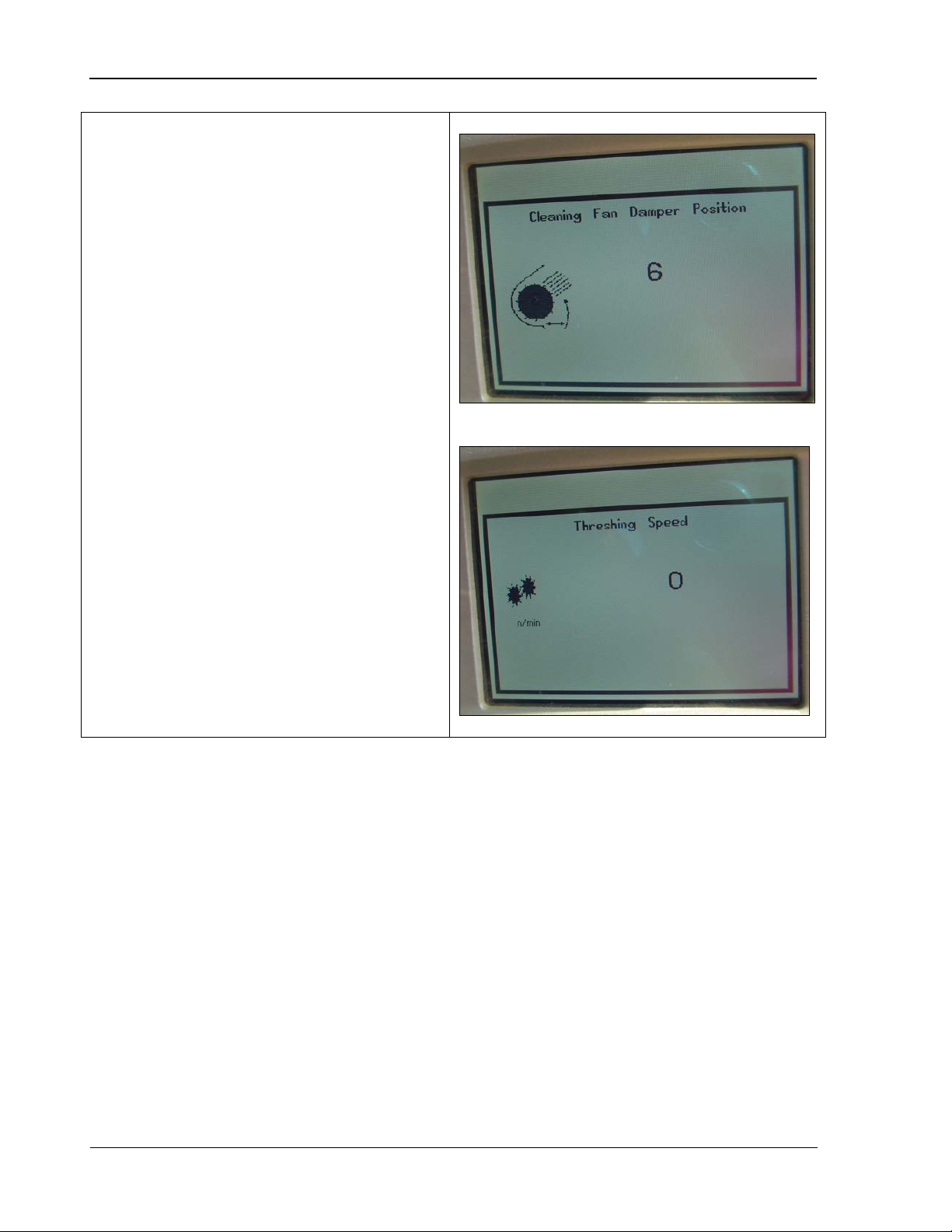
Operator’s Controls 9980 Self-Propelled Peanut Combine
Manual Mode
header and
, the following set points can be
The following set points can be adjusted when
the key switch is ON and the
separator disengaged:
• Cleaning fan damper
• Elevator
With the engine at high idle and the separator
engaged
adjusted:
• T hreshing speed
• Header engaged
• Header speed
48 08/05/16 MAN141.rev1
Page 61
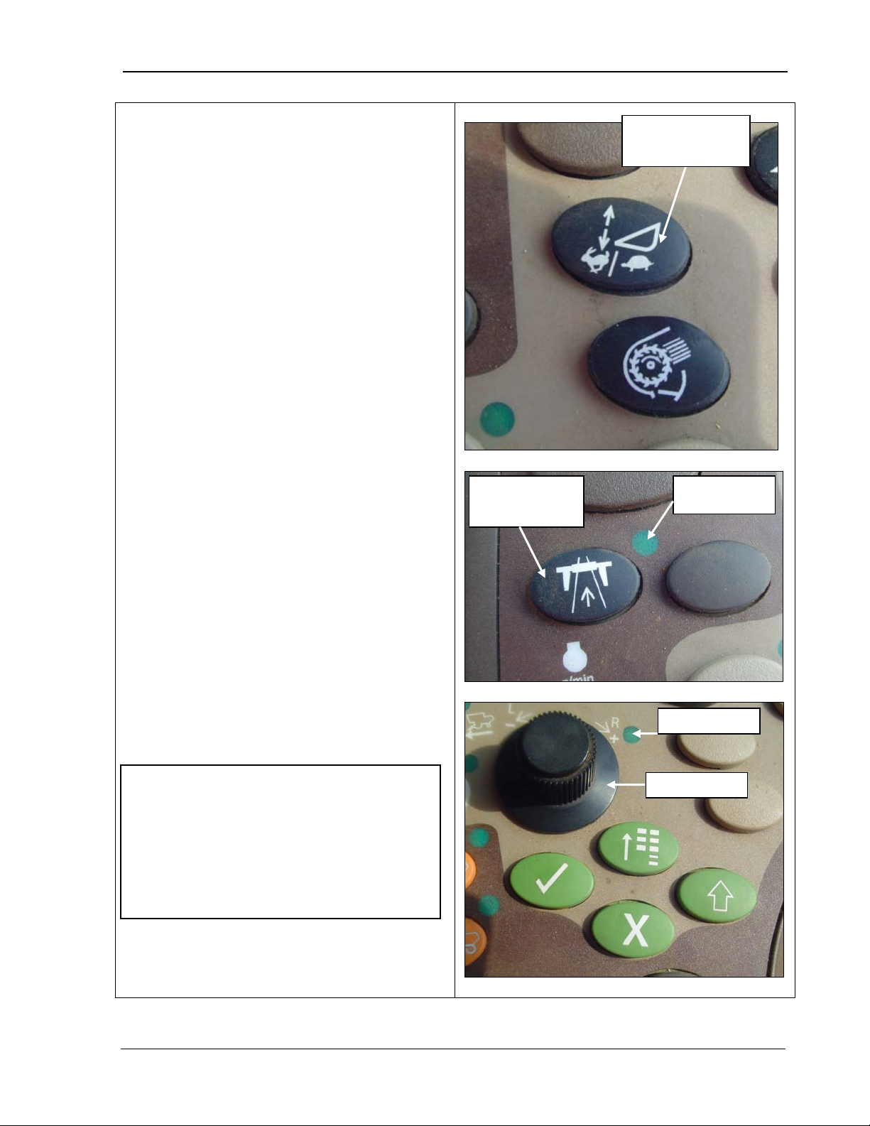
9980 Self-Propelled Peanut Combine Operator’s Controls
Feeder House
and controls the horizontal and vertical
positions of the header. The system
continuously compares the preset position to
the actual position, making adjustments to
keep the header in the selected working
the road transport disconnect
Select the desired feeder house adjust
to select
to select the
header height sensitivity adjust. The
, indicating you can
Turn the selection dial (bottom photo)
) symbol to decrease the response
The CommandCenter
screen displays the operator adjustment
Feeder house rate/
NOTE! Press the confirm switch to make
Road transport
Indicator light
Selection dial
Indicator light
Rate/Sensitivity Adjust
The feeder house rate/sensitivity adjust button
allows you to compensate for uneven ground
position.
1. Make sure
indicator light is OFF (middle photo).
2.
setting:
• Press t he feeder rate sensitivity adjust
switch (top photo) once
manual raise/lower speed.
• Press t he feeder rate sensitivity adjust
button (top photo) twice
selection indicator light turns ON
(bottom photo)
make a c hange.
3.
towards the plus (+) symbol to increase the
response rate/sensitivity or towards minus
(rate/sensitivity.
sensitivity adjust
disconnect
setting.
the feeder house rate/sensitivity icons
disappear on the CommandCenter.
For more detailed information, refer to
“Automatic Header Height Control System”
in Chapter 5, CommandCenter Display.
MAN141.rev1 08/05/16 49
Page 62
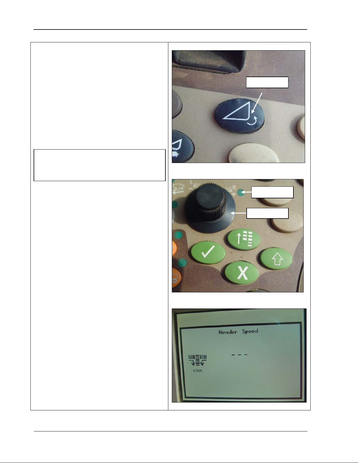
Operator’s Controls 9980 Self-Propelled Peanut Combine
Header Speed
Header speed controls how fast the header
Press the header speed button (top
photo). The selection dial indicator light
).
Selection dial
Indicator light
Header speed
NOTE! The engine must be running and
auger and pickup are rotating. To speed up
or slow down the header:
1.
turns ON (middle photo).
2. Use the selection dial (middle photo) to
turn the speed up (+) or slow it down (The CommandCenter displays adjustment
to the header speed (bottom photo).
both the separator and header engage d to
change this speed.
50 08/05/16 MAN141.rev1
Page 63
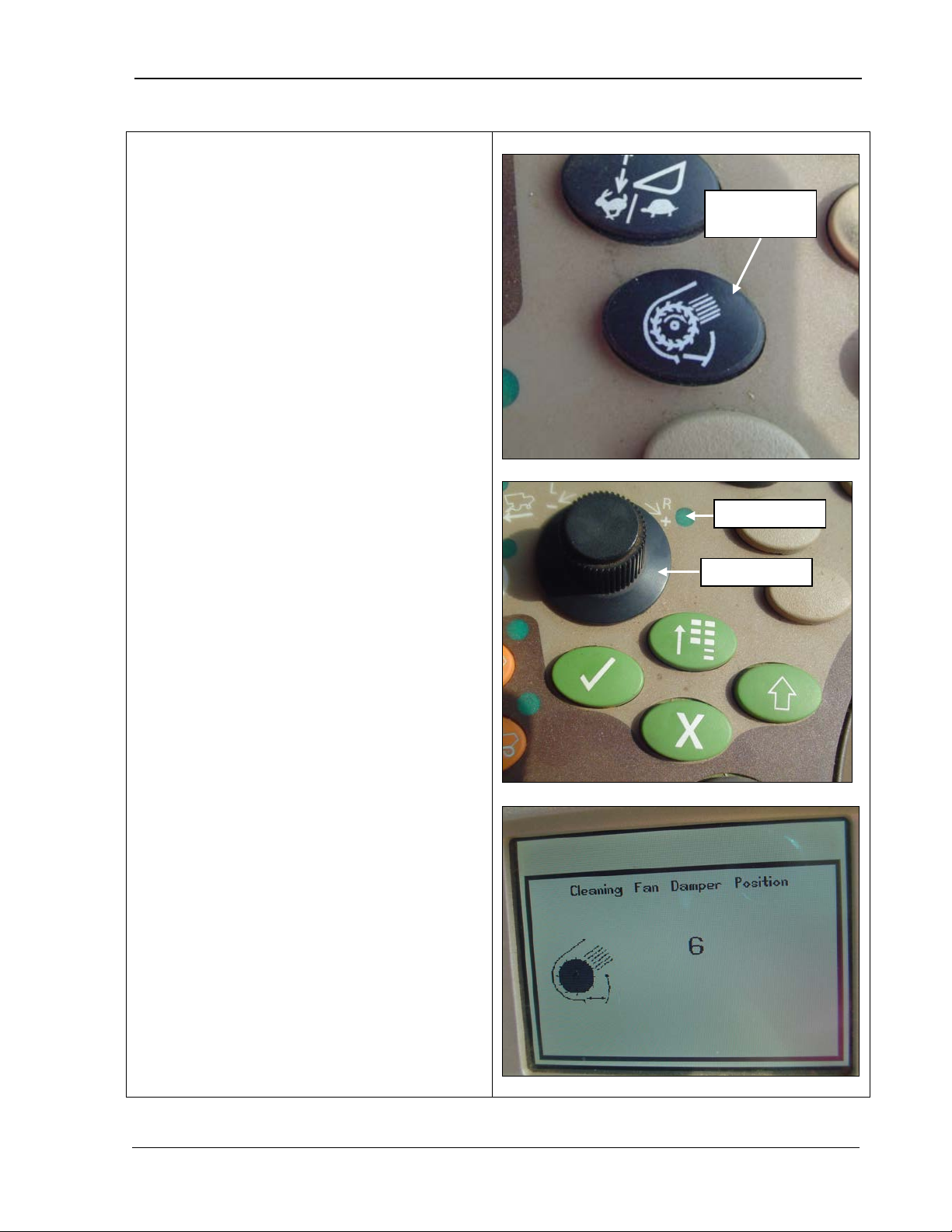
9980 Self-Propelled Peanut Combine Operator’s Controls
Cleaning Fan Damper
far open or closed the clean fan damper is.
Use the selection dial (middle photo) to
).
Selection dial
Indicator light
Cleaning fan
damper
The cleaning fan damper switch controls how
The position is shown as a number.
1. Press the cleaning fan damper button (top
photo). The selection dial indicator light
turns ON (middle photo).
2.
turn the speed up (+) or slow it down (The CommandCenter displays adjustment
to the cleaning fan damper (bottom
photo).
MAN141.rev1 08/05/16 51
Page 64
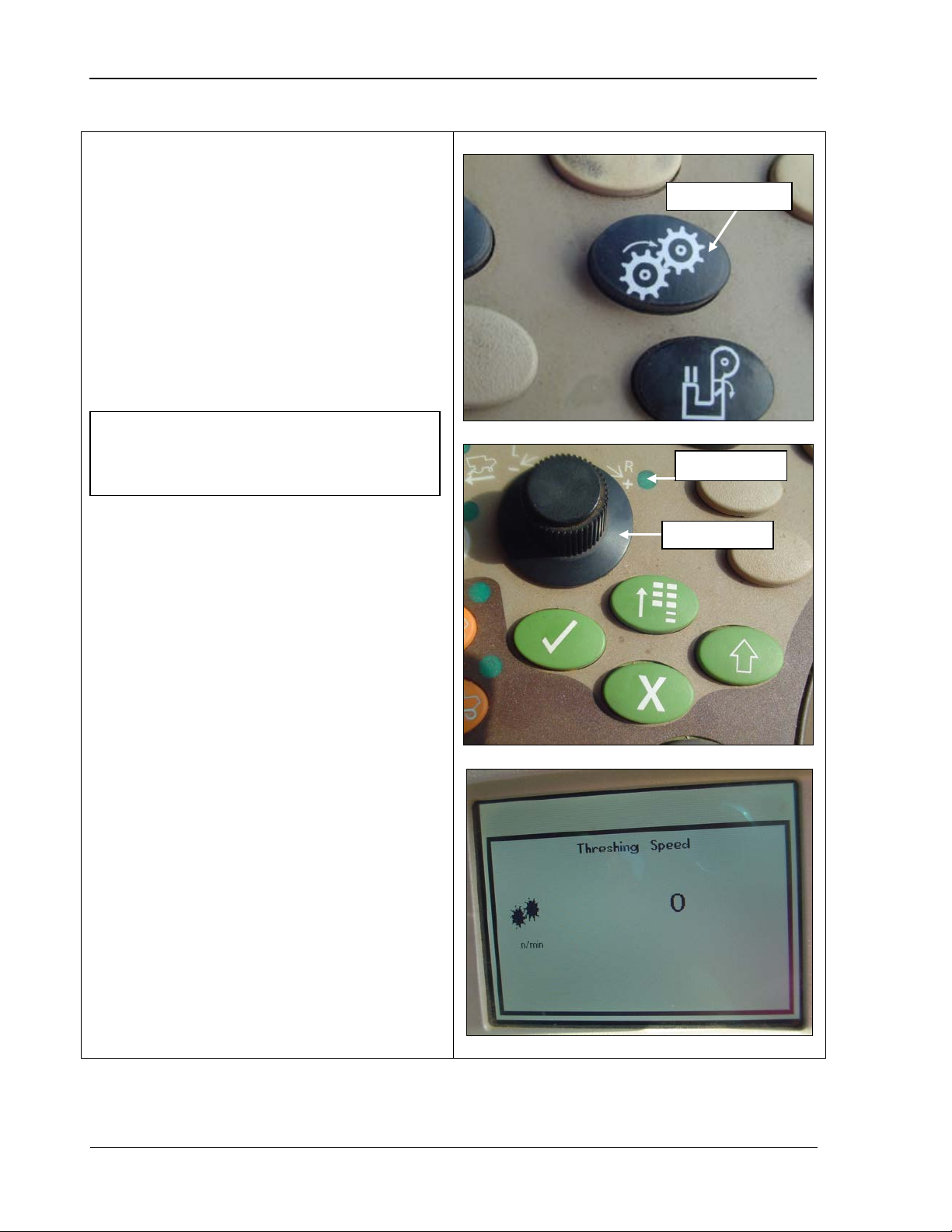
Operator’s Controls 9980 Self-Propelled Peanut Combine
Threshing Speed
photo). The selection dial indicator light
Use the selection dial (middle photo) to
).
The CommandCenter displays adjustment
Selection dial
Indicator light
Threshing speed
NOTE! The engine must be running and
the separator engaged to change this
The threshing speed switch controls the RPM
of the last two threshing cylinders.
1. Press the threshing speed switch (top
turns ON (middle photo).
2.
turn the speed up (+) or slow it down (-
to the threshing speed (bottom photo).
speed.
52 08/05/16 MAN141.rev1
Page 65
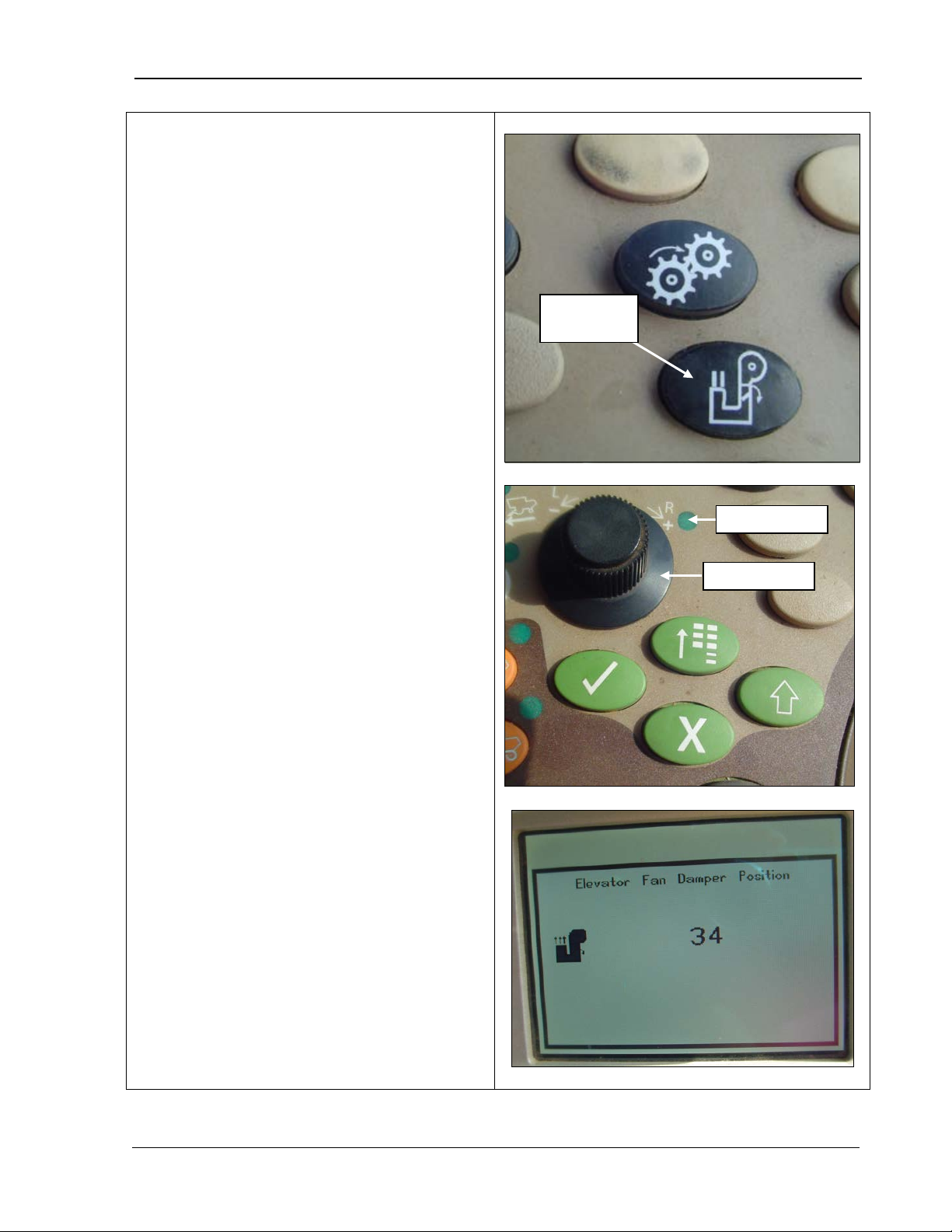
9980 Self-Propelled Peanut Combine Operator’s Controls
Elevator Fan Damper Speed
The elevator fan damper switch controls the
The volume is
photo). The selection dial indicator light
Use the selection dial (middle photo) to
mandCenter displays adjustment to
Selection dial
Indicator light
Elevator fan
elevator fan air volume.
displayed and controlled as a number.
3. Press the elevator fan damper switch (top
turns ON (middle photo).
4.
turn the volume up (+) or reduce it (-). The
Com
the elevator fan damper (bottom photo).
damper
MAN141.rev1 08/05/16 53
Page 66
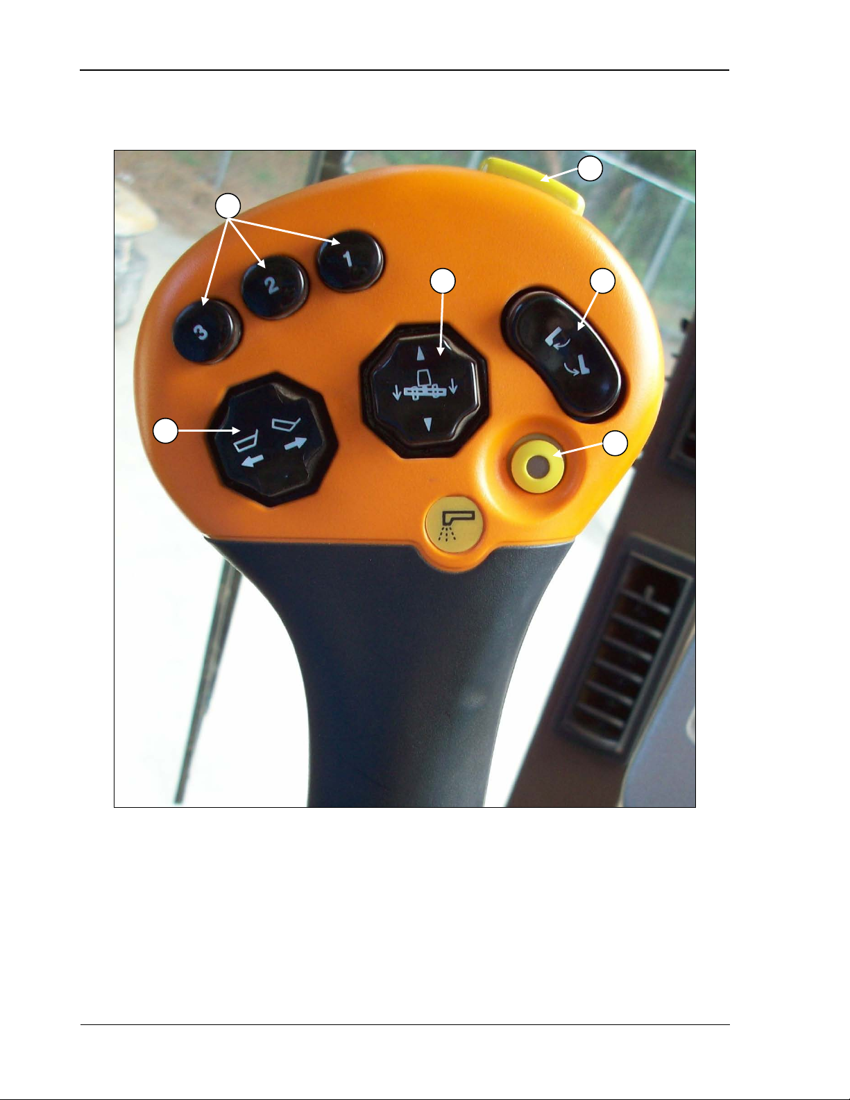
Operator’s Controls 9980 Self-Propelled Peanut Combine
A – Quick stop
E – Conveyor swing out (if OCS
(OCS only)
A B C D E
F
Multifunction Handle
B – Header height control
C – Basket lift
D – Header lift
54 08/05/16 MAN141.rev1
equipped) OR bin lip extend and
retract (if dump basket equipped)
F – Unloading conveyor switch
Page 67
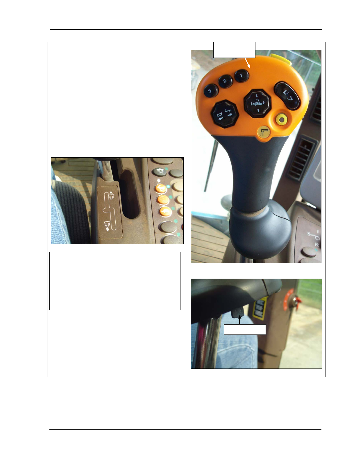
9980 Self-Propelled Peanut Combine Operator’s Controls
Multifunction Handle Use
function handle controls the
The handle’s palm rest is adjustable up and
down in three positions. To move the palm
as in the symbol
All buttons are explained on the following
NOTE! If the hydro charge pressure
the filter. If this does not correct the
Release lever
Multifunction
handle
The multicombine’s forward and backward motion.
rest up or down, release the lever (bottom
photo) and move the palm rest until it catches
into position.
Move the lever forward for the combine to g o
forward. Move the lever to the right and
rearward to go backward
below.
warning comes on in the armrest display
panel when the lever is moved, check the
hydrostatic/hydraulic oil level and replace
problem, see your AMADAS/John Deere
dealer.
pages.
MAN141.rev1 08/05/16 55
Page 68
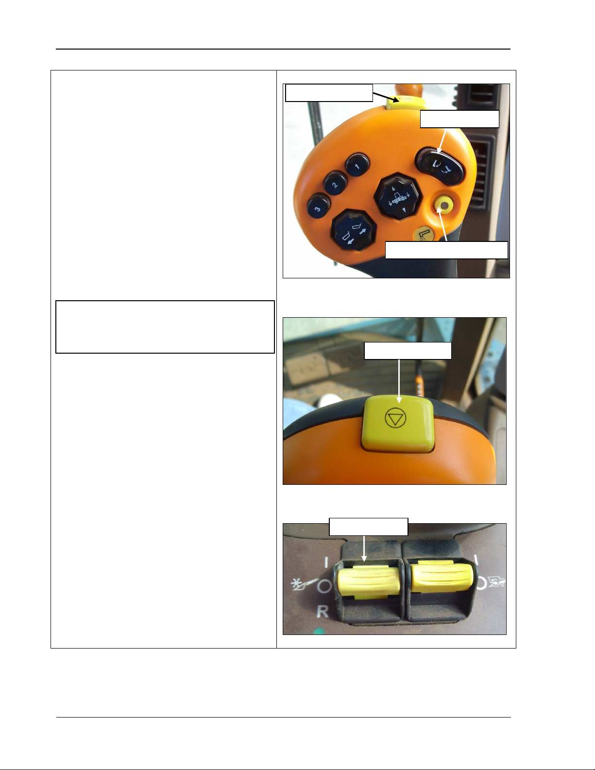
Operator’s Controls 9980 Self-Propelled Peanut Combine
Quick Stop Switch
(top and middle
immediately shuts off all of the
Press the switch once to stop all of these
opriate button on the handle (top
IMPORTANT! The header drive can be
Quick stop switch
Header engage
Quick stop switch
Unloading conveyor drive
Conveyor swing
The quick stop switch
photos)
following:
• Header engage
• Unloading conveyor drive
• Conveyor swing
items at the same time.
To restart the conveyor swing or drive, press
the appr
photo). To restart the header drive, turn the
header engage switch located on the armrest
panel on and off (bottom photo).
disengaged immediately by the Quick Stop
switch in case of malfunctions.
56 08/05/16 MAN141.rev1
Page 69
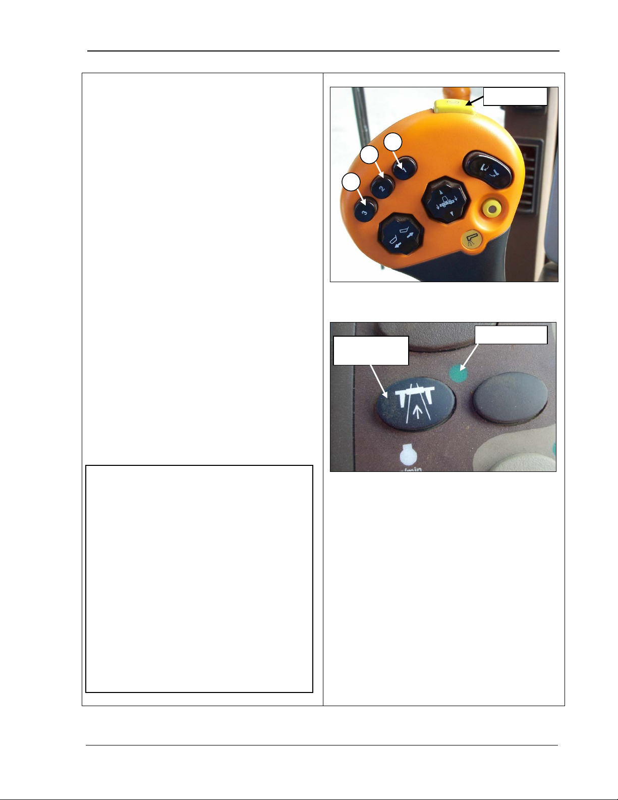
9980 Self-Propelled Peanut Combine Operator’s Controls
Header Height Activation
The header height activation buttons perform
The electronic control system moves the
selected.
on buttons
activates the system and moves the header
A properly equipped header must be
The road transport switch indicator light
Quick stop
A B C
Road transport
disconnect
Indicator light
NOTES!
You can override the header height
position when set by the header
activation buttons by pressing the
height sensing.
Buttons
the following functions:
• Header height resume (A)
• Header height sensing (B) and (C).
header back to the position you prePressing the header activati
into position.
In order to use:
•
connected.
• T he engine must be running.
•
must be OFF (bottom photo).
• T he header must be engaged.
• Header height resume and header height
sensing must be enabled.
•
header lift button. Once overridden,
you can then press the activation
buttons again to reset the header to
the pre-selected height.
• If only Height resume is active, A, B,
and C control different set points for
height resume.
• If only Height sensing is active, A, B,
and C control different set points for
MAN141.rev1 08/05/16 57
Page 70
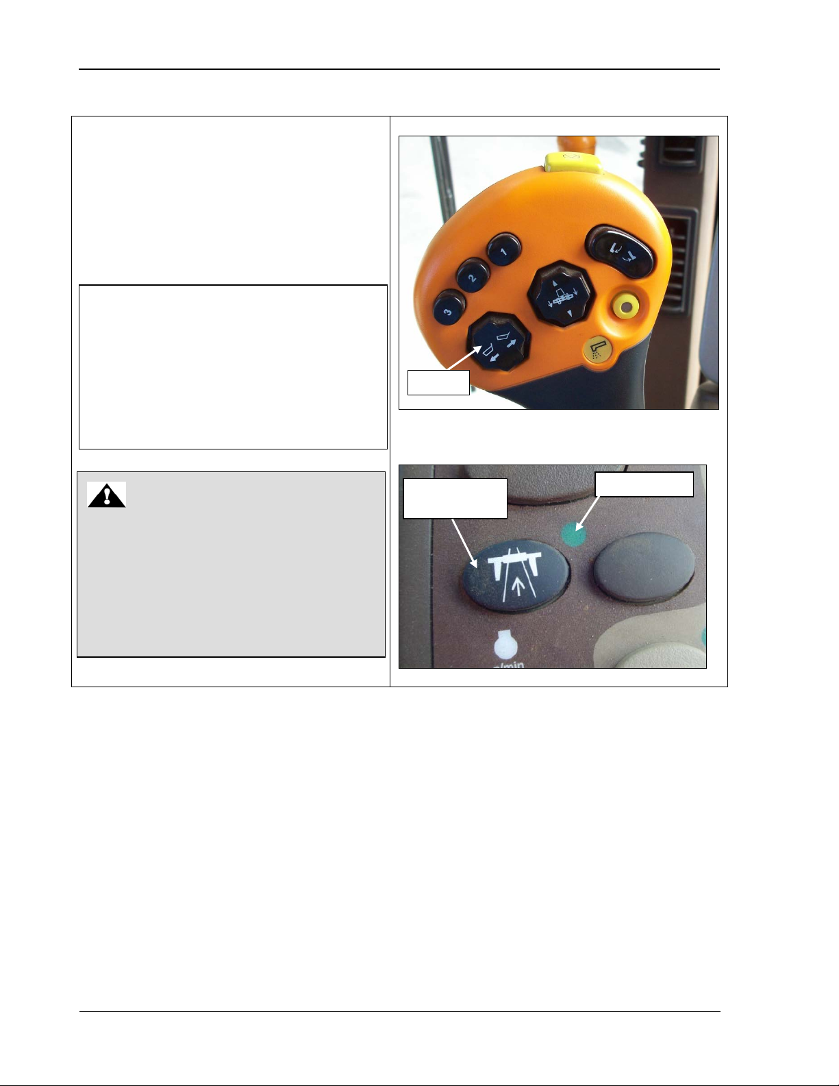
Operator’s Controls 9980 Self-Propelled Peanut Combine
Bin Lift
The bin lift switch controls the lifting and
NOTE! For this switch to work:
The indicator light for the road
transport disconnect switch must be
DANGER
Before lifting the peanut bin, check
obstructions exist. Contact with an
death, electrocution, or serious personal
Bin lift
Road transport
disconnect
Indicator light
lowering of the peanut bin as follows:
• Push and hold the right of the switch to
raise the bin
• Push and hold the left to lower the bin.
• T he engine must be running to raise or
lower the peanut bin.
•
OFF (bottom photo).
overhead clearance to make sure that no
power lines, overhead limbs, or any other
obstruction or power line could result in
injury.
58 08/05/16 MAN141.rev1
Page 71
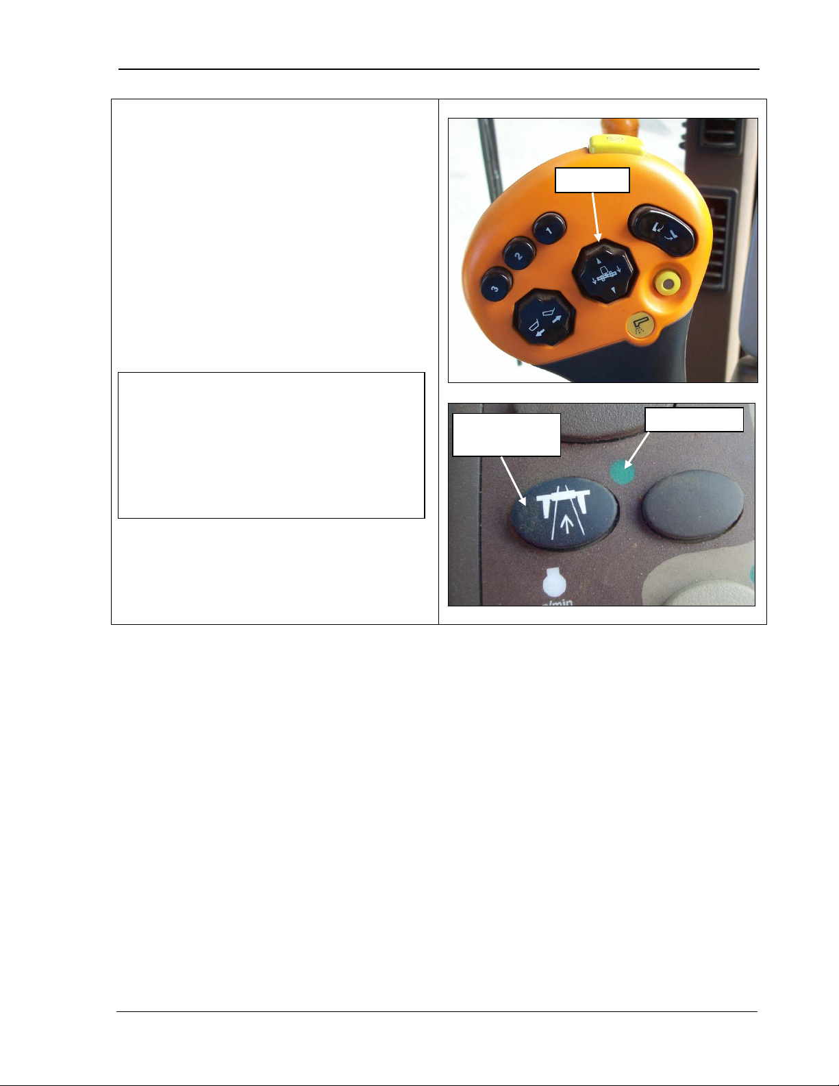
9980 Self-Propelled Peanut Combine Operator’s Controls
Header Lift Switch
ch raises and lowers the
Press and hold the top of the button to
part way in to raise or lower the header
NOTE! For this switch to work:
The indicator light for the road
transport disconnect switch must be
Header lift
Road transport
Indicator light
The header lift swit
header as follows:
•
raise the header.
• Press and hold t he bottom of the button to
lower the header.
• T he switch has two detent positions. Push
slowly; push all the way in to lower or raise
the header at a faster rate.
•
disconnect
OFF (bottom photo).
• T he operator must be seated.
MAN141.rev1 08/05/16 59
Page 72
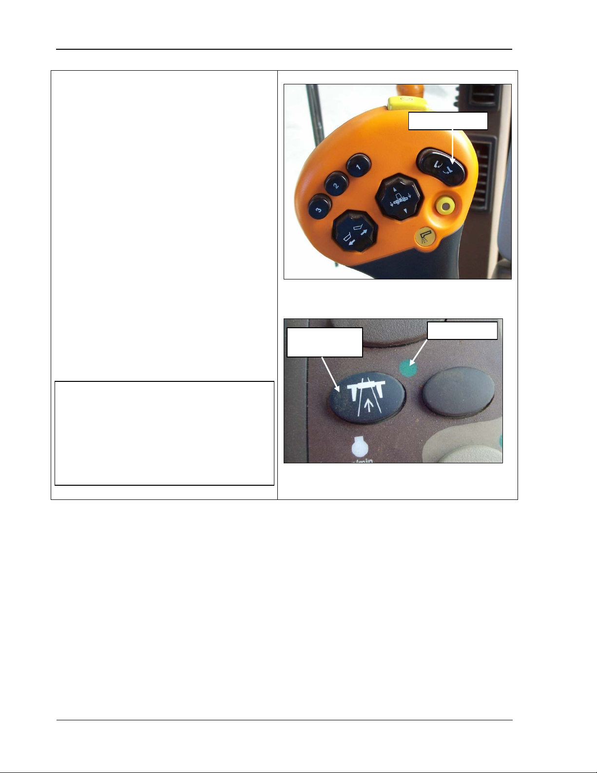
Operator’s Controls 9980 Self-Propelled Peanut Combine
Conveyor Swing Switch
This switch is used to swing the Unloading
Conveyor in or out for combines equipped
If your combine is NOT equipped
of the switch to swing the
This switch has two stages. The first
detent you feel in either direction is for
manual control. If the switch is
completely pressed and held for three
seconds, the operation in that direction
continues automatically. Any change in
position cancels the automatic
Conveyor swing
NOTE! For this switch to work:
The indicator light for the road
transport disconnect switch must be
Road transport
disconnect
Indicator light
OR
Dump Combine Lip Extend and Retract
with the Off-load Conveying System (OCS)
option.
with the OCS option, it is used to extend and
retract the bin lip and to dump the bin.
• To use the switch, press the bottom of
the switch to swing the conveyor out or
extend the bin lip, as applicable.
• Press the top
conveyor back in or retract the bin lip.
•
switch
mode.
•
OFF (bottom photo).
• T he operator must be seated.
60 08/05/16 MAN141.rev1
Page 73
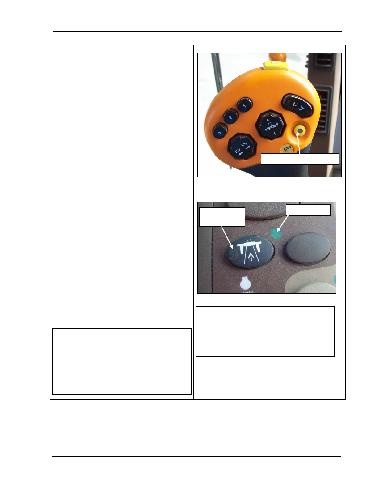
9980 Self-Propelled Peanut Combine Operator’s Controls
Unloading Conveyor Drive
option.
To start the unloading conveyor, press
the button. A light in the middle of the
o stop the conveyor, press the button
you can also use the Quick Stop switch.
If you stop the unloading conveyor with
this switch, press the unloading button
is pressed if the
conveyor is less than 50% extended.
Once the conveyor has passed 50%
unloading conveyor drive will stay
engaged until the button is pressed and
NOTE! A five-second time lag is factory
Unloading conveyor drive
Road transport
Indicator light
NOTE! For this switch to work:
The indicator light for the road
transport disconnect switch must be
Button
(Off-load Conveying System (OCS) option
only)
The unloading conveyor drive switch is used
for combines equipped with the OCS
It is used to turn the unloading drive on the
conveyor on and off.
•
button comes on to indicate the conveyor
is unloading.
• T
again. The light goes out to indicate the
conveyor has stopped.
• If you need to stop the conveyor quickly,
once to start up the conveyor again.
• T he unloading conveyor will engage only
while the button
extension and t he button is pressed, the
released again or the quick stop button is
pushed.
•
• T he operator must be seated.
OFF (bottom photo).
disconnect
set for the conveyor, which means the
unloading auger starts five seconds after
the conveyor. To change the lag time, see
Chapter 13, Unloading Conveyor.
MAN141.rev1 08/05/16 61
Page 74
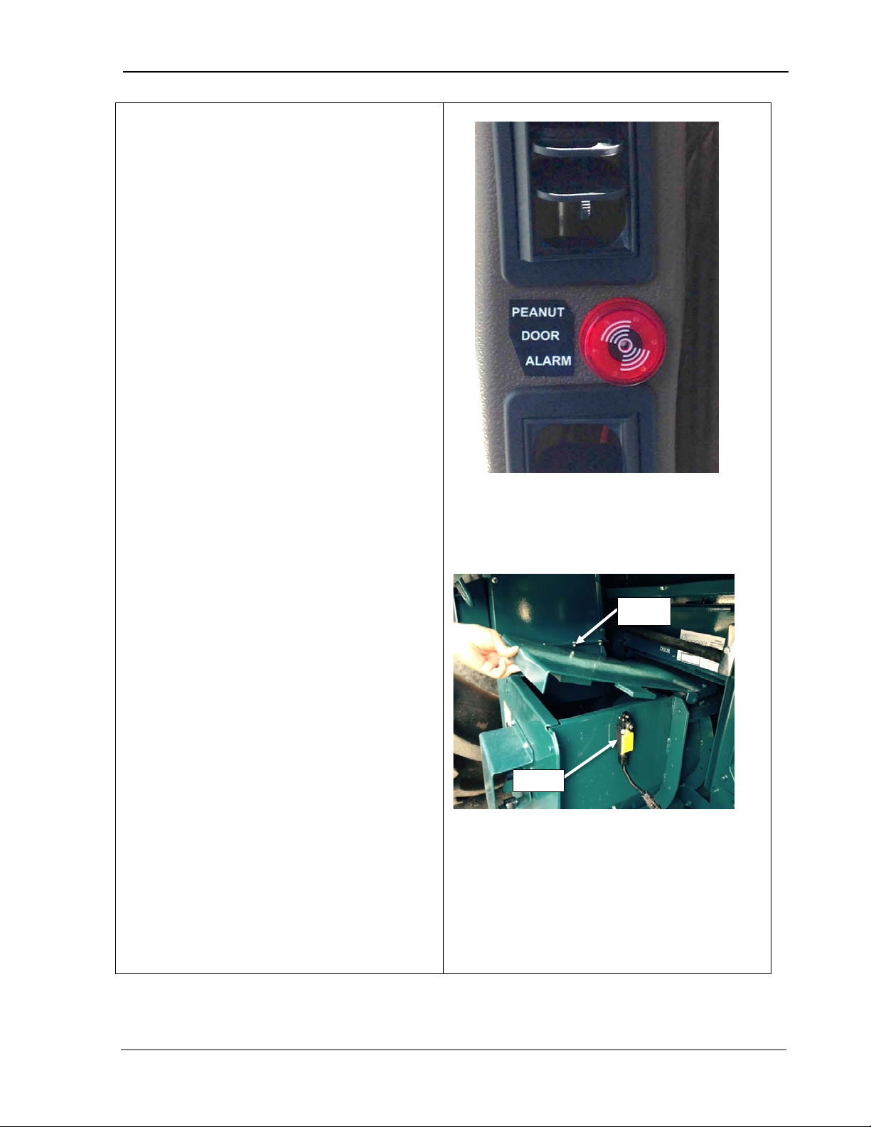
9980 Self-Propelled Peanut Combine Operator’s Controls
Peanut Door Alarm
above the collection auger (bottom photo)
This may be caused by a blockage in the
If the alarm sounds, address this
Stop the combine, disengage the
separator and header and shut off
Engage the parking brake and
peanuts are not packed under the
door, close and ensure that the
clearing, inspect the auger flighting
ting is bent or
welds are broken, repair before
If no duct blockage was found,
Door
Alarm
The Peanut Door Alarm (top photo), provides
an audible and visual alarm when the door
has opened.
peanut duct, insufficient air flow for the crop
volume or an over-filled basket.
NOTE!
issue immediately.
•
the engine.
•
remove the ignition key.
• If
switch is activated.
• If peanuts ar e packed under the door,
open the inspection door below the
auger and release the peanuts. After
for damage. If fligh
continuing harvest.
•
reduce harvesting speed or increase
elevator air.
MAN141.rev1 08/05/16 62
Page 75

9980 Self-Propelled Peanut Combine Overhead Control Panel
4.
Overhead Control
Panel
Overhead Control Panel .......................... 65
ClimaTrak™ Automatic Temperature
Control ................................................. 66
Mirror Control Switch ............................ 67
Mirror Heater Switch ............................ 68
Windshield Wiper Switch and Optional
Windshield Washer .............................. 69
Deere-Delco AM/FM Radios (Optional).... 70
Radio With Weatherband ..................... 71
Setting Clock .................................... 71
General Receiver Functions ............. 71
Turning on Power ............................. 71
Display ............................................. 71
Setting Default Displa y ..................... 72
Adjusting Brightnes s of Display ........ 72
Adjusting Receiver Settings .............. 72
Weatherband ....................................... 73
Radio Programming for Local Area
Frequency ............................................ 74
Radio with Weatherband and CD Player
............................................................. 75
General Receiver Functions ............. 75
Turning on Power ............................. 75
One-Hour Timer ................................ 75
Display ............................................. 75
Programmable Eject Default ............. 76
MAN141 09/04/15 63
Page 76

Overhead Control Panel 9980 Self-Propelled Peanut Combine
CD Button Functions ............................ 77
Playing a Compact Disc .................... 78
Operating Tips About Your Audio System
............................................................. 79
Understanding Radio Reception ....... 79
Antenna ............................................... 80
Communications/CB Radio Mounting ... 80
64 09/04/15 MAN141
Page 77
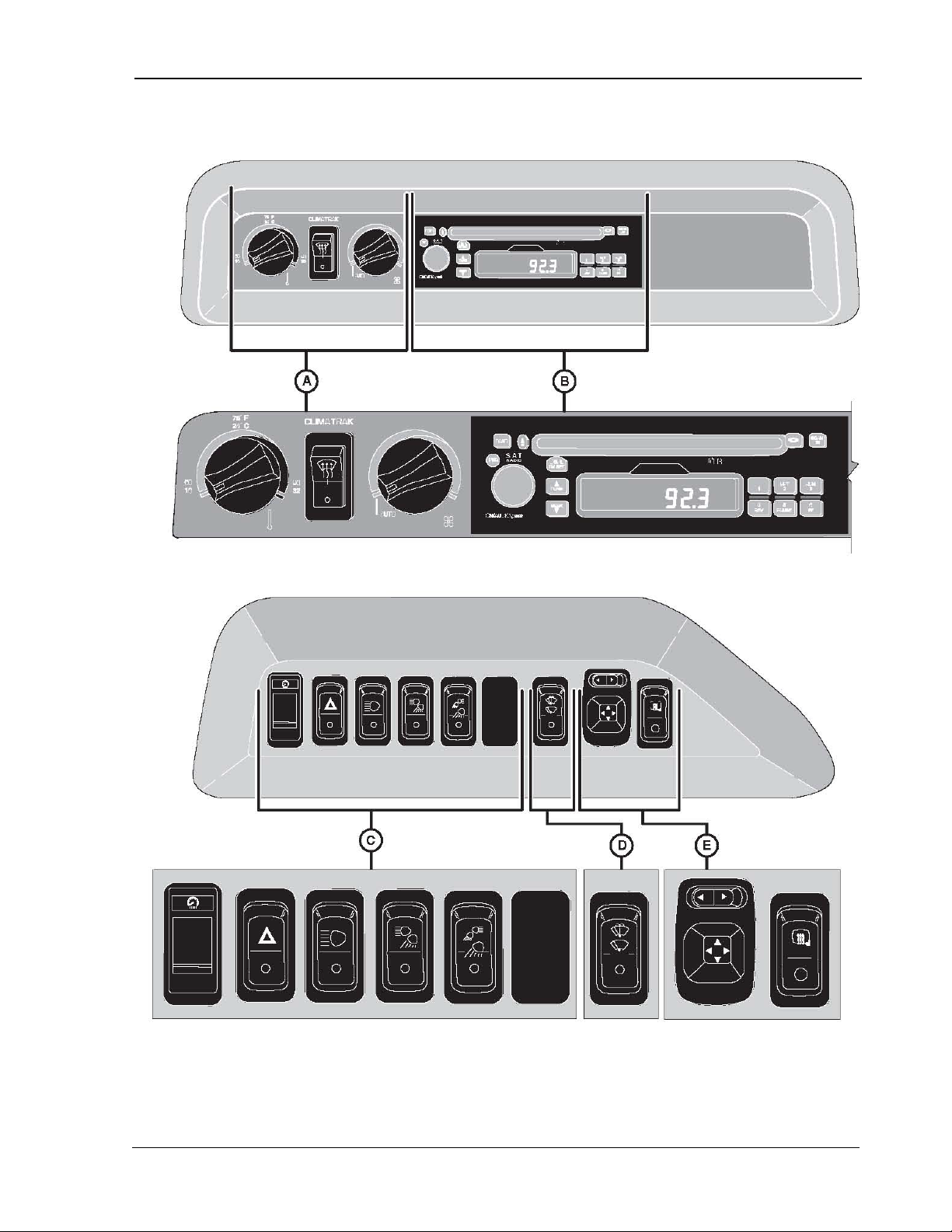
9980 Self-Propelled Peanut Combine Overhead Control Panel
A – CLIMATRAK Control Switches
C – Light Switches
D – Windshield Wiper/Washer Switch
Overhead Control Panel
B – Deere-Delco Radio
MAN141 09/04/15 65
E – Mirror Adjust/Heater Switch (Optional)
Page 78
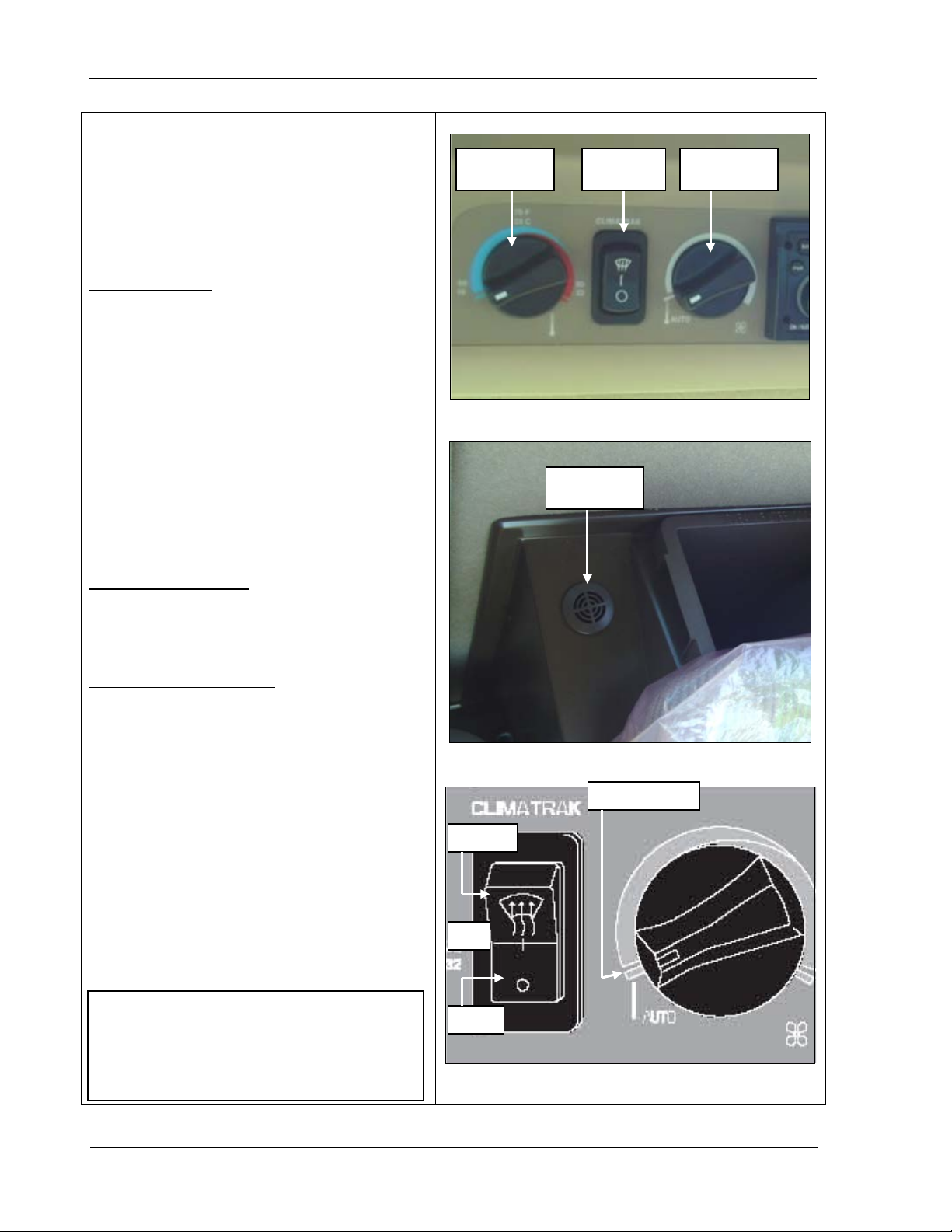
Overhead Control Panel 9980 Self-Propelled Peanut Combine
ClimaTrak™ Automatic
control speed dial (top photo) and the
This switch functions as
In the OFF position, all power to the
In the DEFOG position, power is
moisture from the air, even in heat
This dial controls air
the temperature or counterclockwise to
This dial controls
recirculation fan, which controls the
The dial has a detent position, marked
AUTO, for automatic speed setting. In
the difference between the selected
temperature and the actual cab
Temperature
sensor
Fan control
speed dial
Mode
selector
Temperature
control dial
DEFOG
ON
OFF
AUTO setting
NOTE! The temperature sensor is
located behind the instructional seat.
Make sure it remains uncovered or
system may not operate properly in
AUTO mode.
Temperature Control
The CLIMATRAK control system consists of
temperature control dial, mode selector, fan
temperature sensor (middle photo).
Mode Selector:
follows (see sketch):
•
CLIMATRAK system is off.
• In t he ON position, power is supplied for
normal functions.
•
supplied to the compressor regardless of
the set temperature. This helps remove
mode.
Temperature Control:
temperature. Turn it clockwise to increase
decrease the temperature.
Fan Speed Control Dial:
the
amount of air coming out of the louvers. It
functions as follows:
• T urn the dial clockwise to allow more air
or counterclockwise for less air.
•
this position, fan speed is determined by
temperature. As the temperature
approaches the set point, the fan s peed
decreases.
66 09/04/15 MAN141
Page 79
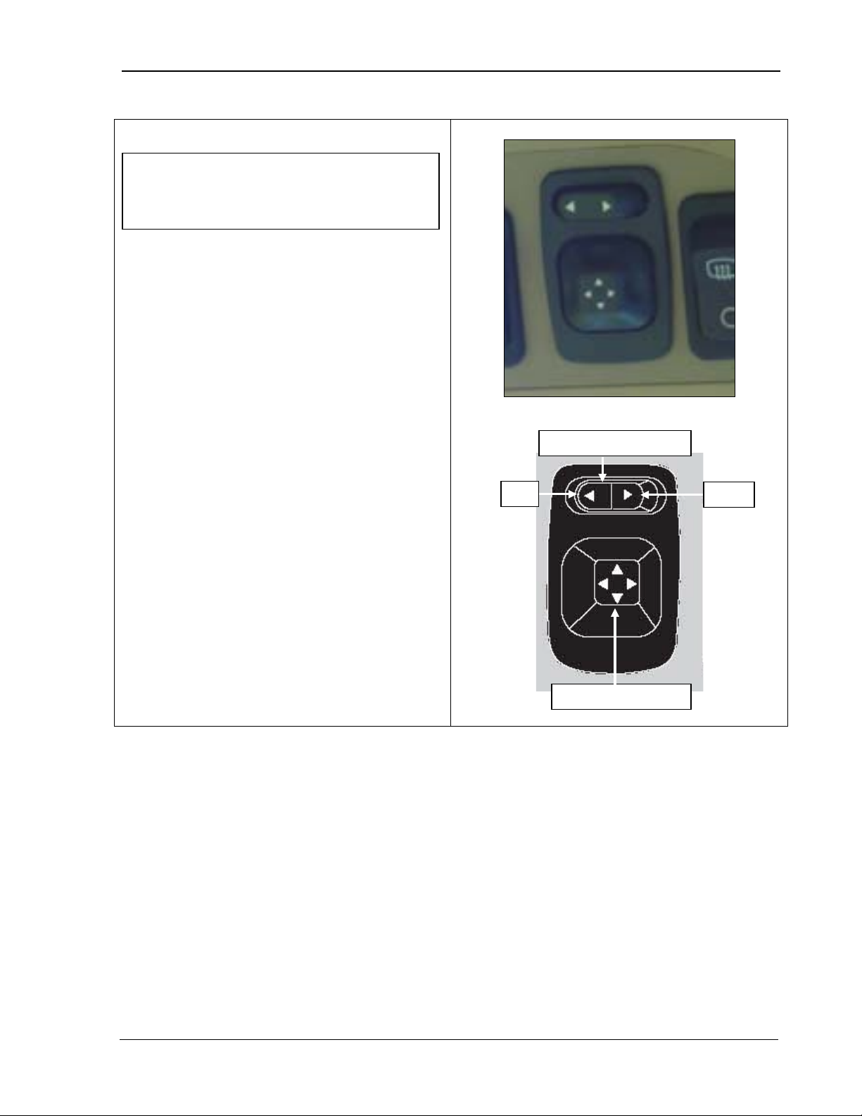
9980 Self-Propelled Peanut Combine Overhead Control Panel
Mirror Control Switch
fers power
hand mirror,
allowing you to move each mirror up, down,
move the
NOTE ! The key switch must be ON or the
Right
Left
Mirror Control switch
Mirror adjust switch
machine must be running in order to use
the mirror cont ro l s .
The mirror control switch trans
between the left-hand and right-
left, or right.
To adjust the mirror:
1. Press the left side of the switch to power
the left-hand mirror or right side to power
the right-hand mirror.
2. Use the mirror adjust switch
mirror right, left, up or down.
MAN141 09/04/15 67
Page 80
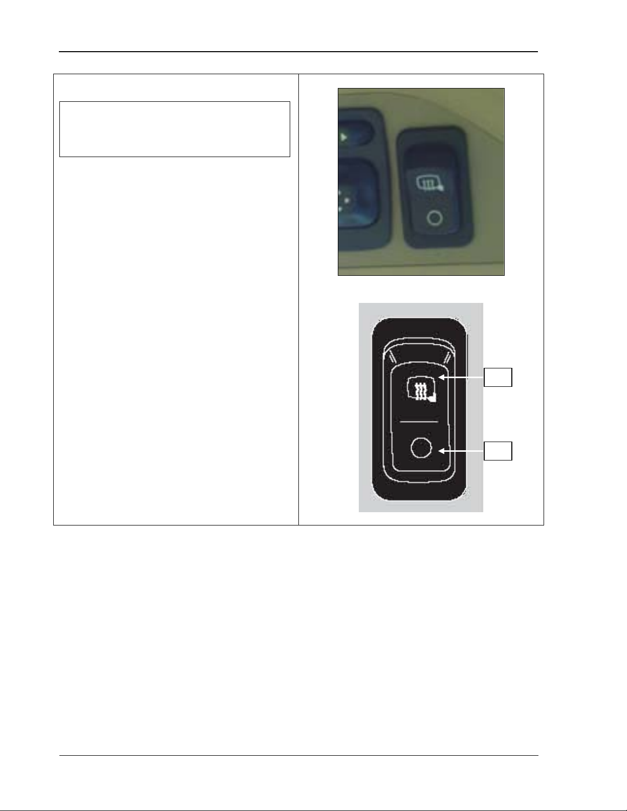
Overhead Control Panel 9980 Self-Propelled Peanut Combine
Mirror Heater Switch
The combine side mirrors are equipped with
heaters to remove ice and fog. The mirror
OFF two position
the bottom to turn it off.
Remember that the heater does not turn off
ON
OFF
NOTE ! The key switch must be ON or the
machine must be running in order to use
the mirror cont ro l s .
heater switch is an ONswitch. Press the top of the switch to turn the
heater on and
automatically.
68 09/04/15 MAN141
Page 81

9980 Self-Propelled Peanut Combine Overhead Control Panel
Windshield Wiper Switch and
The windshield wiper switch functions as
The extra long wiper can be stopped on
when the switch is returned to the OFF
the windshield. The spray will continue
NOTE! A windshield washer is available
OFF
ON
NOTE ! The key switch must be ON or the
WASH
Optional Windshield Washer
machine must be running in order to use
the windshield wiper controls.
follows:
•
either side of the windshield, depending on
position.
• W hen the switch is in the OFF position, all
power to the wiper system is turned off.
• Press O N for the wiper to move back and
forth.
• Press and hold W ASH to spray liquid onto
until you release the switch.
from your AMADAS/ John Deere dealer for
use with the full view wiper.
MAN141 09/04/15 69
Page 82
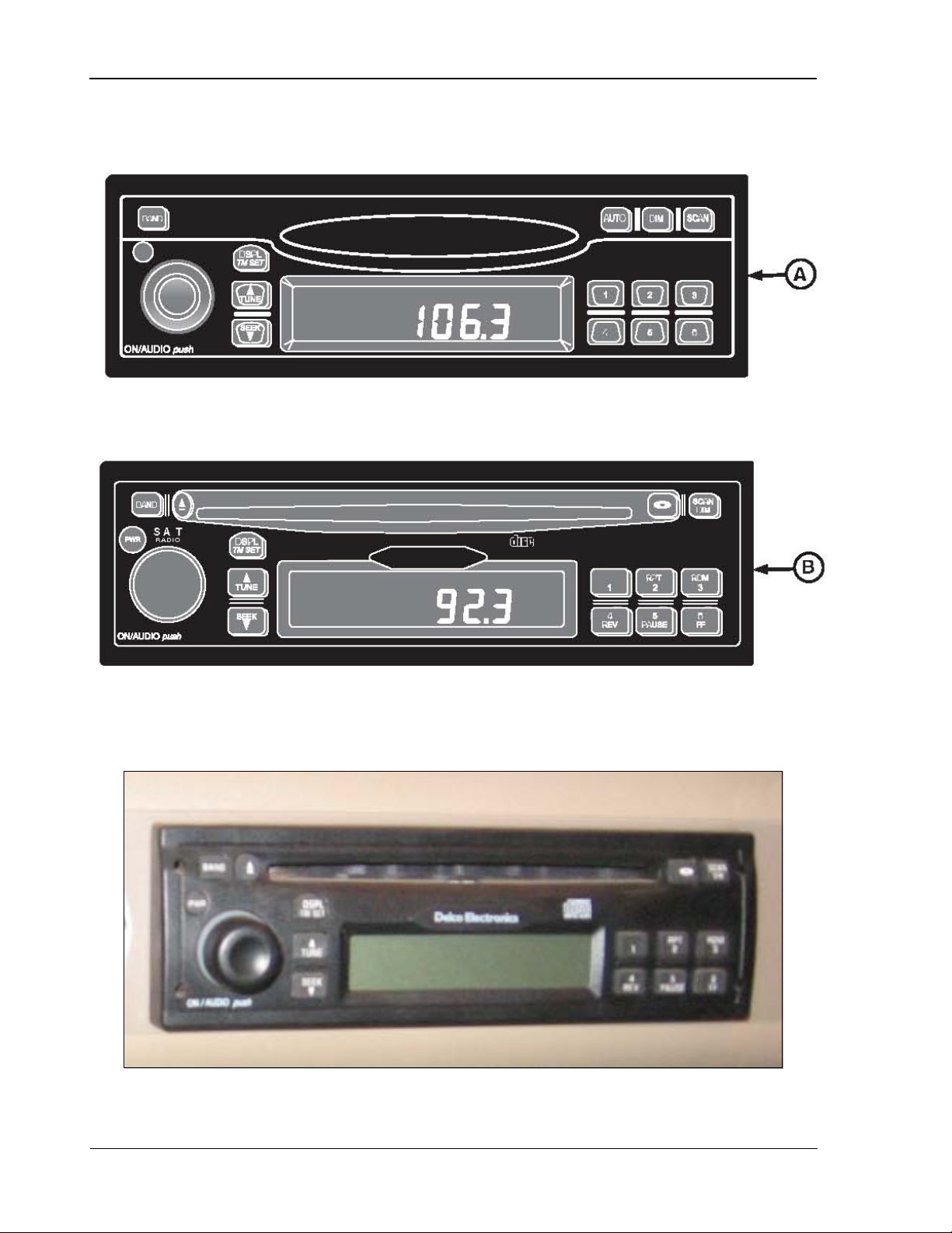
Overhead Control Panel 9980 Self-Propelled Peanut Combine
A – AM/FM Stereo Radio and Weather Band
B – AM/FM Stereo Radio and CD Player
Deere-Delco AM/FM Radios (Optional)
70 09/04/15 MAN141
Page 83
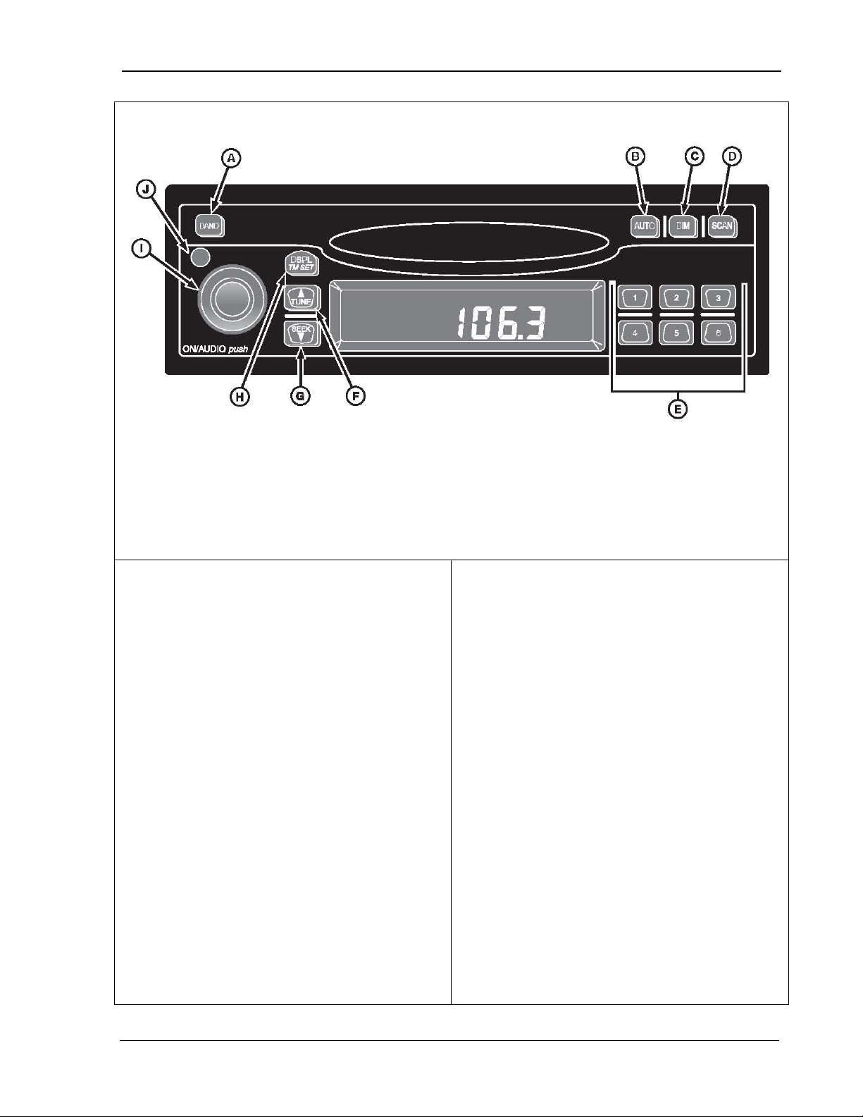
9980 Self-Propelled Peanut Combine Overhead Control Panel
Radio With Weatherband
A. Band AM FM1,
display
D. Scan – scans all
G. Seek – changes
I. On/Audio – power/
Setting Clock
Press DSPL/TM SET button again and
Press TUNE (up arrow) or SEEK button
tting is changed. After five seconds of
inactivity, display will return to default and
The receiver is equipped with two FM radio
When the ignition is ON, you can turn the
(J). Pressing the ON/AUDIO knob (l) also
when receiver is on allows you to toggle
FM2, Weatherband
B. Auto - stores
strongest stations
to presets
C. Dim – adjusts
brightness or
stations in current
band
E. Push buttons – 1-6
preset stations
F. Tune – changes
radio station
1. Turn ignition ON.
2. Press and hold DSPL/TM SET button (H)
until hour digits flash.
3. Press TUNE (up arrow) (F) or SEEK button
(down arrow) (G) to set correct hour.
4.
minutes digits will flas h .
5.
(down arrow) to set correct minute.
Seconds are reset to zero when the minutes
se
clock will be set.
General Receiver Functions
bands, FM1 and FM2. The two bands are the
radio station
H. Displ/Tm Set –
changes display;
switches to time set
mode
volume/receiver
settings
J. Pwr - power
same, but allow you to set six presets in each
band, for a total of 12 FM presets.
Turning on Power
receiver on or off by pressing the power button
activates the receiver.
Display
The receiver displays the time of day when it is
turned off.
Momentarily pressing DISPL/TM ST button (H)
between displays.
When the receiver is in AM, FM1, FM2, or WX,
the display toggles between the frequency and
time of day.
MAN141 09/04/15 71
Page 84

Overhead Control Panel 9980 Self-Propelled Peanut Combine
Setting Default Display
Press and hold DISPL/TM SET button for
button 6 to change display
After five seconds of inactivity, the selected
If the dash dimmer does not control the
Press and hold the DIM button (C) until
Rotate the AUDIO knob clockwise to
ightness of the receiver
To adjust Volume, Bass, Treble, Fade, and
Balance, press and release the ON/AUDIO
knob repeatedly until the desired feature
volume and counterclockwise to decrease it.
The display shows “VOL” and the volume
Press AUDIO knob until “BASS” and
o increase bass sound and
present level appear on the display. Rotate
the knob clockwise to increase treble sound
til “FADE” and
clockwise to move sound to front speakers
and counterclockwise to move sound to rear
to move sound to right speakers and
counterclockwise to move sound to left
speakers. After five seconds of inactivity, the
1.
at least two seconds until hour digits flash.
2. Press pushdefault.
default is displayed.
Adjusting Brightness of Display
brightness of the receiver display:
1.
“DIM” and the brightness level appear on
the display.
2.
increase the br
display and counterclockwise to decrease
it.
Adjusting Receiver Settings
Volume: Volume is the default function.
Rotate the AUDIO knob clockwise to increase
level.
Bass:
present level appear on display. Rotate knob
clockwise t
counterclockwise to decrease it.
Treble: Press AUDIO knob until “TREB” and
and counterclockwise to decrease it.
Fade: Press AUDIO knob un
present level appear on display. Rotate knob
speakers.
Balance: Press AUDIO knob until “BAL” and
present level appear. Rotate knob clockwise
receiver will return to the default display.
displays.
72 09/04/15 MAN141
Page 85

9980 Self-Propelled Peanut Combine Overhead Control Panel
Weatherband
of the National Weather service. It provides
continuous broadcasts of the latest weather
more frequently if needed. Most of the
y be
Weatherband mode, the radio displays the
“WX” icon and “CHAN #” to indicate the
channel. The channel may be adjusted
through the TUNE or SEEK buttons. The
The frequency associated with each channel
All of the John Deere radios are equipped with
a weatherband channel.
NOAA Weather Radio is a service of the Voice
information directly from the National Weat her
Service offices. Taped weather messages ar e
repeated every four to six minutes and are
routinely revised every one to three hours or
stations operate 24 hours daily.
The weather for the area you are in ma
found on one of seven stations. When in the
channels may be set on the presets as regular
radio stations.
is:
1 – 162.550 MHz
2 – 162.400 MHz
3 – 162.475 MHz
4 – 162.425 MHz
5 – 162.450 MHz
6 – 162.400 MHz
7 – 162.525 MHz
MAN141 09/04/15 73
Page 86
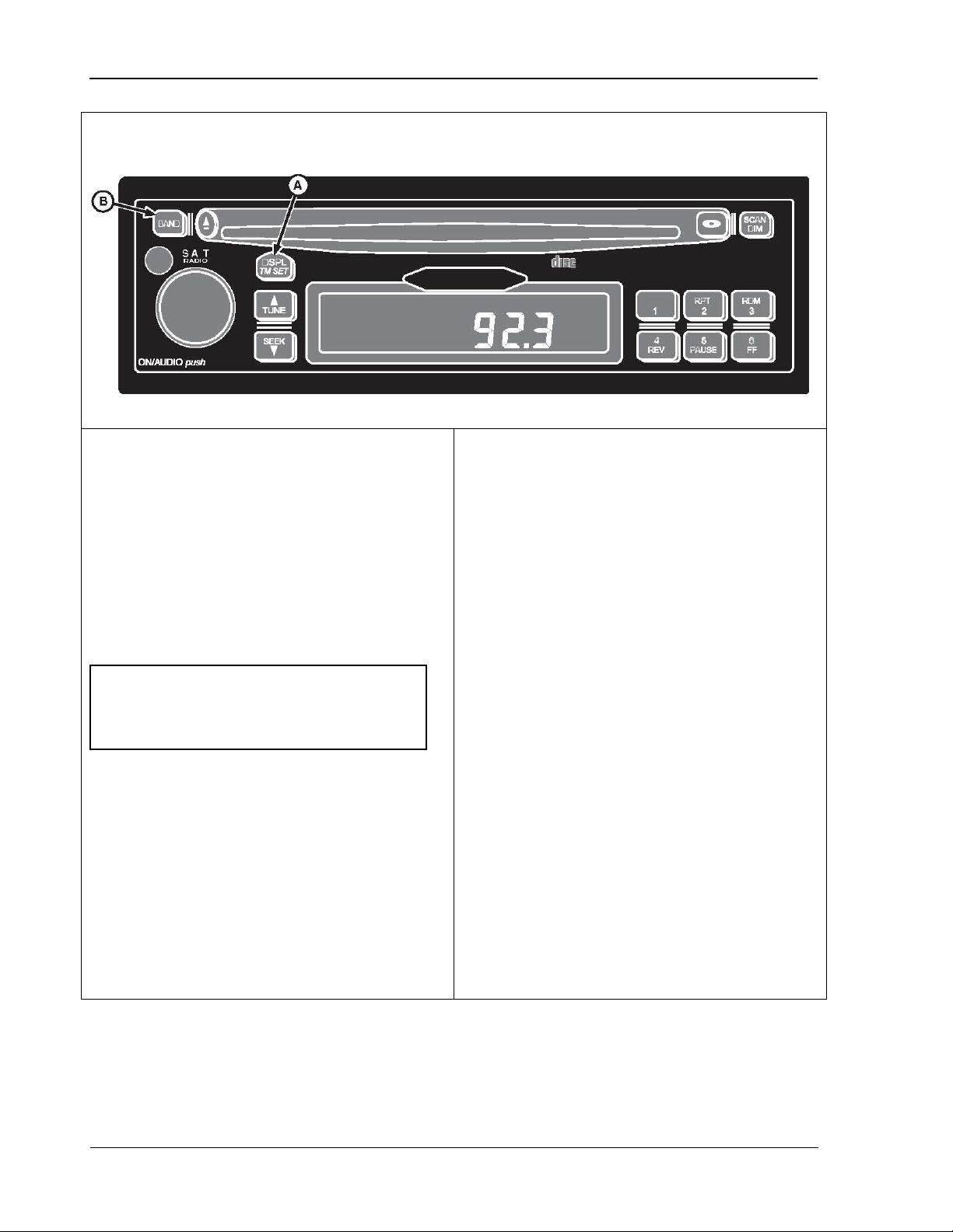
Overhead Control Panel 9980 Self-Propelled Peanut Combine
Radio Programming for Local Area Frequency
A – DSPL/TM SET button
B – BAND button
To verify that the radio is set for North
Turn radio OFF (digital display shows
lia, set radio to
Turn radio OFF (digital display shows
Press and hold DSPL/TM SET button (A)
Immediately press BAND button (B) to
Repeatedly press BAND button to scroll
Stop pressing BAND button when desired
Do not press any buttons for a few
econds; new area frequency setting is in
use when display returns to show current
NOTE! When radio displays “USA”, do
not press any buttons until the radio
2.
American frequencies:
1. Turn key switch ON.
2.
current time).
3. Press and hold the DSPL/TM SET button
(A) until hour-digits start to flash.
display returns to the current time.
4. Immediately press BAND button (B) once.
Radio can be programmed for use in the U.S.
(North America), China, Europe, Argentina, or
Japan. For use in Austra
“EUROPE” setting.
current time).
3.
until hour digits start flashing.
4.
view curr ent setting on digital display.
5.
through available area settings:
U.S.A
EUROPE (use for Australia)
JAPAN
ARGENTINA
CHINA
6.
area appears.
7.
s
To program radio:
1. Turn key switch to ON.
time.
74 09/04/15 MAN141
Page 87
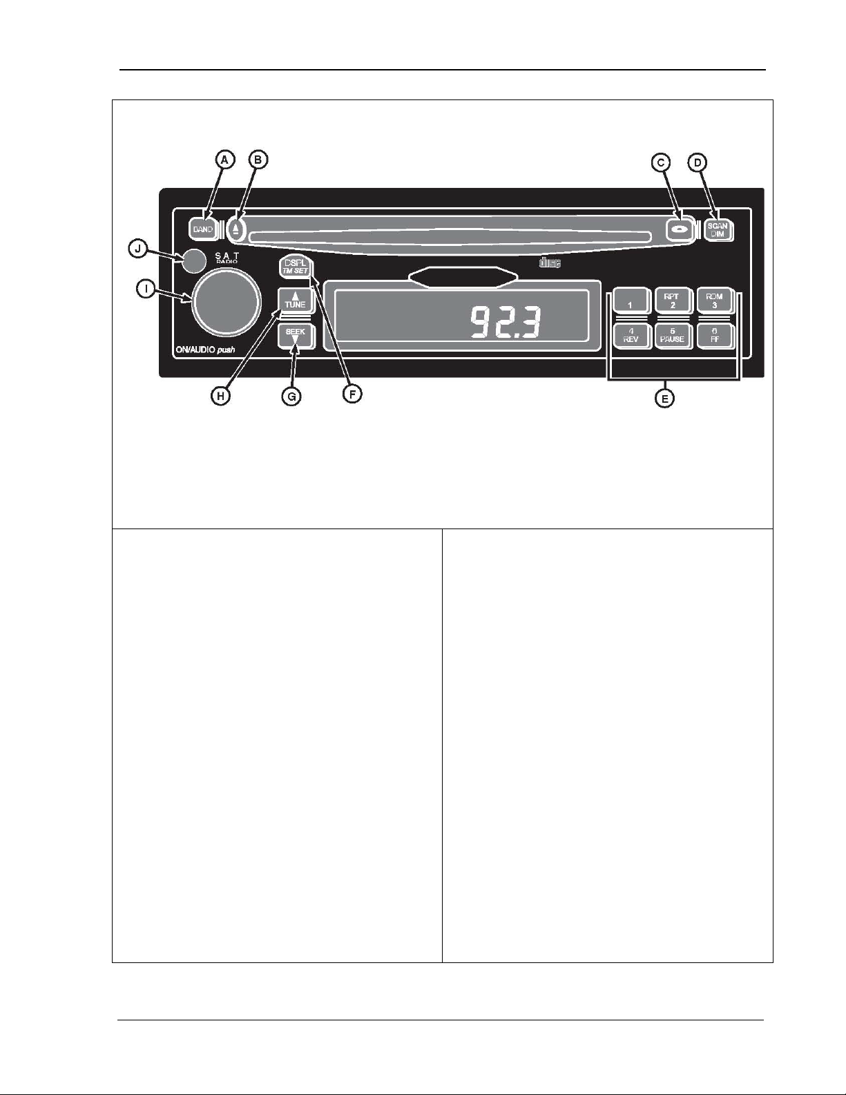
9980 Self-Propelled Peanut Combine Overhead Control Panel
Radio with Weatherband and CD Player
A. Band
D. Cd Changer
F. Dspl/T m Set
I. On/Audio
bands (FM1, FM2, and FM3), but allows six
presets in each band, for a total of 18 FM
or OFF by pressing the PWR button (J).
Pressing ON/AUDIO knob (I) also activates
ON by pressing PWR button or ON/AUDIO
hour timer. The
be reactivated by pressing PWR button or
receiver is OFF. Press the DISP/TM SET
button (F) momentarily when the receiver is
When your receiver is in AM, FM1, FM2,
FM3 or WX, display toggles between the
toggles between track number, elapsed
B. Eject CD
C. CD Mode
Mode
E. Push-button 1-6
preset stations
and CD functions
General Receiver Functions
The receiver is equipped with three FM radio
presets.
Turning on Power
With ignition ON, the receiver may be turned
ON
the receiver.
One-Hour Timer
With the ignition OFF, receiver may be turned
knob activating the on-
receiver turns OFF after one hour . Timer may
G. Seek
H. Tune
J. Pwr
Display
The receiver displays the time of day when the
ON to toggle between displays.
•
frequency and the time of day.
• When in CD or CD changer modes, display
time and time of day.
ON/AUDIO knob again.
MAN141 09/04/15 75
Page 88

Overhead Control Panel 9980 Self-Propelled Peanut Combine
Programmable Eject Default
player is programmed to return to
radio mode once the CD is ejected. This
for two seconds or until the hour digits
Press the CD mode button (C) to toggle
The receiver returns to normal operation after
The CD
default may be reset to “eject audio mute.” In
this mode, the player acts as an independent
source. After ejecting a CD, the audio volume
mutes and the display reads “NO CD”. The
receiver remains muted until the BAND button
is pressed, enabling the radio.
To change the eject default:
1. Press and hold the DPLS/TM SET button
flash.
2.
between P.PLAY and EJMUTE.
seconds of inactivity.
76 09/04/15 MAN141
Page 89
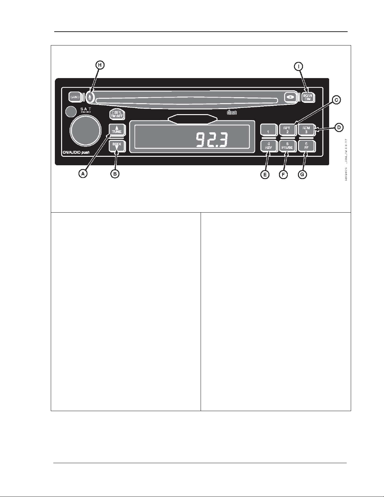
9980 Self-Propelled Peanut Combine Overhead Control Panel
CD Button Functions
A. Tune
C. 2/Rpt
D. 3/Rdm
F. 5/Pause
H. Eject
Forwards to next track. Display
button is pressed during the first eight
seconds, the previous track displays. The
Repeats the current track. The
Activates random track selection.
The “RDM” icon illuminates on the display.
RDM button again to turn the random play
and hold RV to fast reverse.
When released, the CD plays at normal speed.
The display shows the track number and
Pauses the CD; “PAUS”
displays. Press PAUSE again to resume
o fast forward.
normal speed. The display shows the track
the next track on the CD. “SCAN” and the
10 seconds. The CD then advances to the
B. Seek
E. 4/Rev
TUNE (A) –
will show rack number and elapsed time.
SEEK (B) – Reverses to beginning of track. If
display shows the track number and elapsed
time.
2/RPT(C) –
“RPT” icon on display indicates that this
feature is ON.
3/RDM (D) –
Tracks CD plays in random order. Press the
function OFF with the next track played.
4REV (E) – Press
G. 6/FF
I. Scan/Dim
5/PAUSE (F) –
playing the CD.
6/FF (G) – Press and hold FF t
When the button is released, the CD plays at
number and elapsed time.
EJECT (H) – Press to eject a CD.
SCAN/DIM (I) – Press SCAN to scan all tracks
on the CD. The player immediately advances
to
track number display while the track plays for
next track and plays it for 10 seconds. Pres s
SCAN again to deactivate.
elapsed time.
MAN141 09/04/15 77
Page 90

Overhead Control Panel 9980 Self-Propelled Peanut Combine
Playing a Compact Disc
Insert a disc partway into the slot (label
side up). The player automatically pulls
the disc once it has been partially inserted.
ime and the track
CD button to play a CD that has been
ack number and
A CD can be inserted while the receiver is
player mode, the following
no CD has been loaded in the
the lens could not focus on the CD.
eject and
clean D lens with a lens
wait an hour and try
Loss of tracking control.
with a lens
The integral CD receiver plays full-sized CDs.
1. Turn the ignition and receiver ON.
2.
The “CD” icon displays along with the track
number and elapsed t
plays.
3. If you are listening to the radio, press the
loaded into the player. If no CD has been
loaded, “NO CD” displays for five seconds
and then the default displays. If a CD has
been loaded, the tr
elapsed time on the track displays.
If a CD is ejected and not removed within 25
seconds, the CD reloads.
OFF. To do so, press EJECT and insert a CD
within 25 seconds.
Error Messages
While in CD
messages may appear:
NO CD –
player.
FOCUS –
Possible reasons include:
• Disc is inserted upside down –
reinsert CD.
• Disc is dirty, scratched, or wet – clean CD.
• Lens is dirty –
cleaner.
• It is very humid –
again.
TRACKING –
Possible reasons include:
• Disc is dirty or scratched – try cleaning CD.
• Lens is dirty – clean CD lens
cleaner.
MOTOR ER – Loads/unloads motor problem –
contact dealer.
78 09/04/15 MAN141
Page 91

9980 Self-Propelled Peanut Combine Overhead Control Panel
Operating Tips About Your
Hearing damage from loud noise is almost
Adjust the volume control to the lowest
FM stereo gives you the
best sound, but FM signals only reach about
can interfere with FM signals, causing the
night. The longer
range, however, can cause stations to
pick up noise from things like storms and
IMPORTANT! Before you add any
It is important that all equipment be
added properly to minimize these
Your vehicle’s systems may interfere
t, check with
sure to check Federal regulations
covering mobile radio and telephone
Audio System
undetectable until it is too late. Your hearing
can adapt to high volumes of sound. Sound
that seems normal can be loud and harmful to
your hearing. Take precautions by adjusting
the volume control on your receiver to a saf e
sound level before your hearing adapts to it.
To help avoid hearing loss:
•
setting.
• Increase the volume slowly until you hear
comfortably and clearly.
Understanding Radio Reception
FM STEREO: The
additional sound equipment, such as a
CB radio, mobile phone, or two-way
radio, to your machine, make sure there
will be no machine interference. Added
sound equipment can interfere with the
operation of your vehicle’s engine, radio,
or other system, and even damage them.
potential problems.
with the operation of sound equipment
that has been added improperly. Before
adding sound equipmen
your dealer about proper installation. Be
units.
16-65 km (10-40 miles). T all buildings or hills
sound to come and go.
AM: The range for most AM stations is greater
than for FM, especially at
interfere with each other. AM radio can also
power lines. Try reducing the treble to r educe
this noise if you experience it.
MAN141 09/04/15 79
Page 92
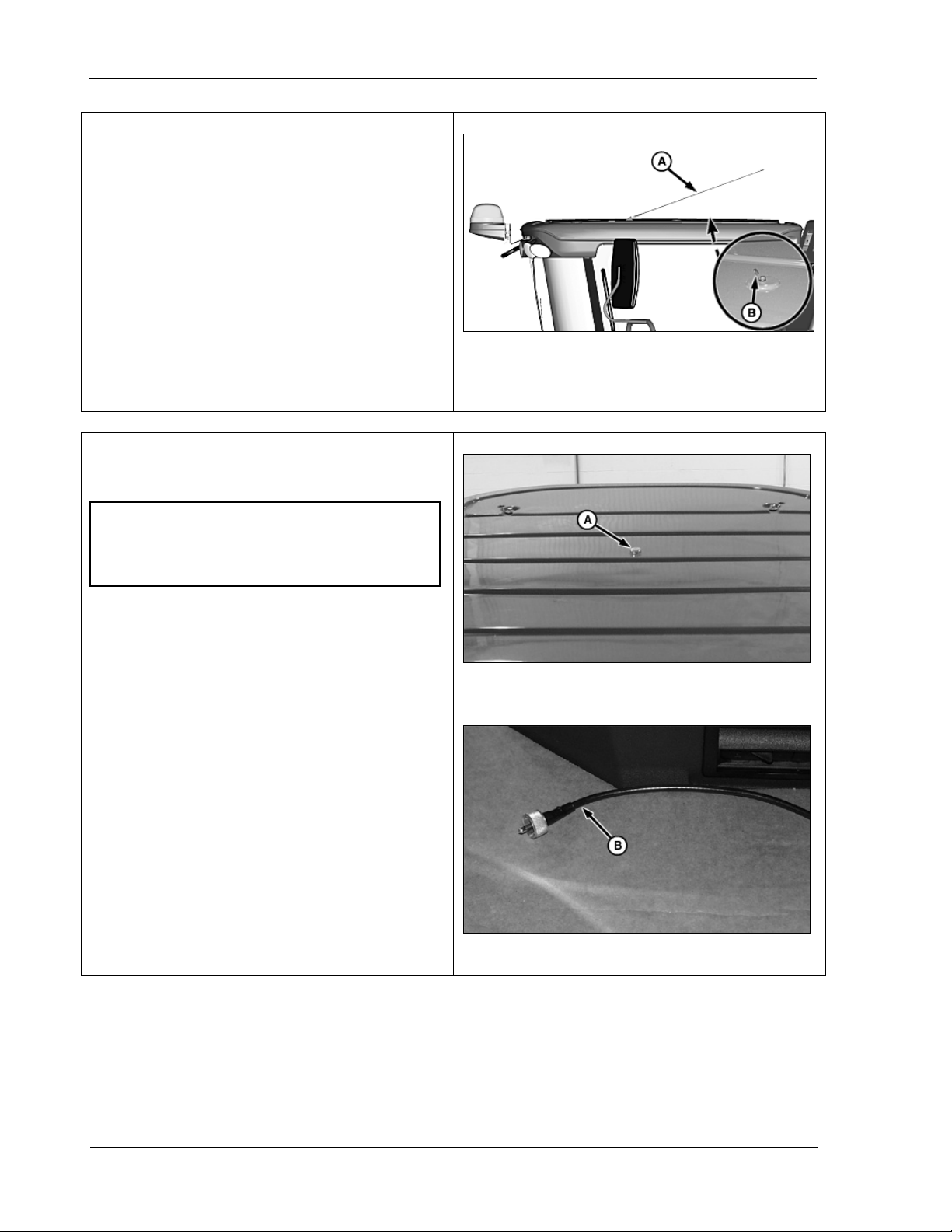
Overhead Control Panel 9980 Self-Propelled Peanut Combine
Antenna
not used or machine is being
transported, fold radio antenna down and
Communications/CB Radio
IMPORTANT! Do NOT install a radio
If the reception is poor, check if the antenna
(A) is in the upright position.
If the radio is
retain with hook (B).
Mounting
requiring more than 3 AMPS or electrical
system may malfunction.
To install an additional radio or CB radio, see
your John Deere dealer.
The antenna mount (A) is located in center of
cab roof. The antenna cable (B) is located on
right-hand side of cab under the armrest.
A – Antenna
B – Hook
A – Antenna mount
80 09/04/15 MAN141
B – Antenna cable
Page 93
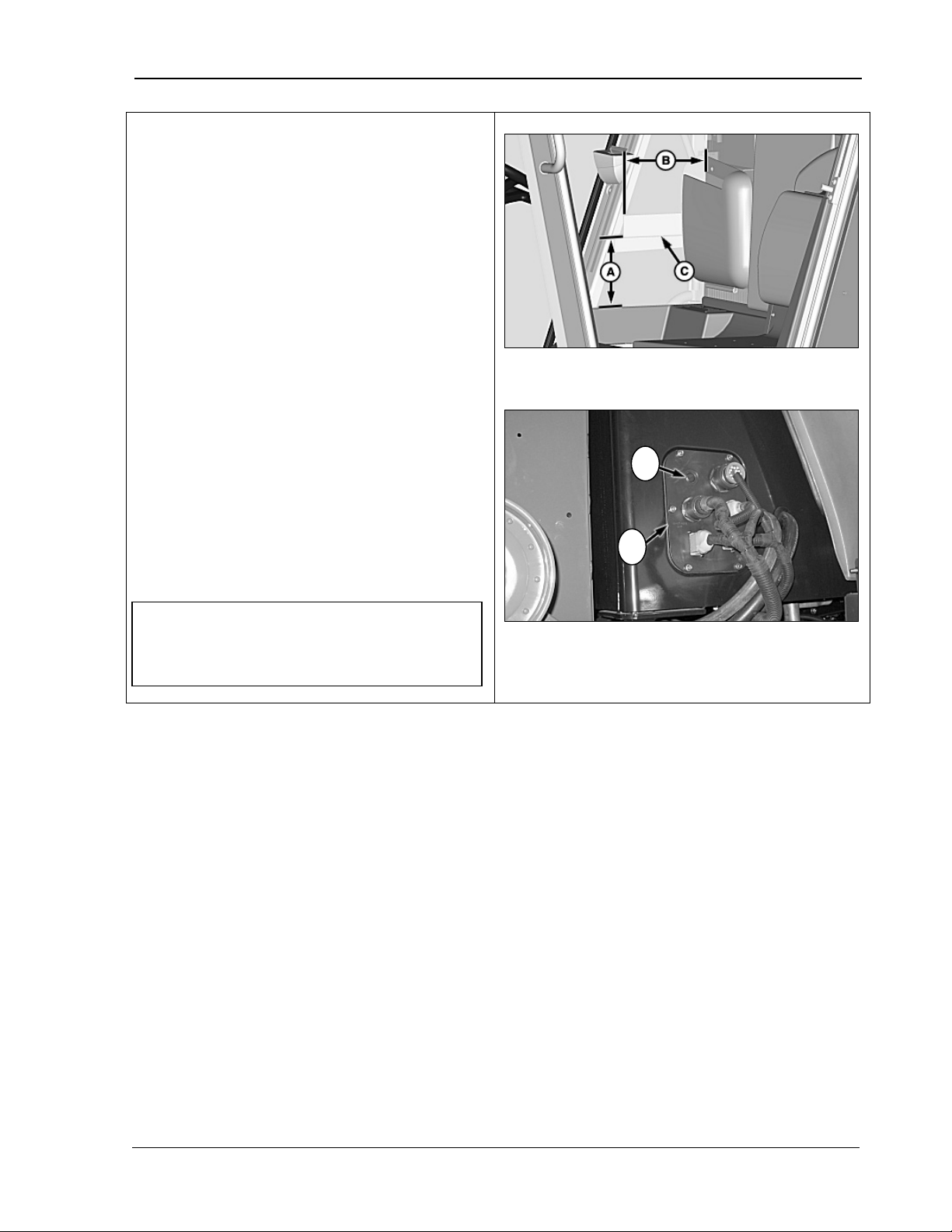
9980 Self-Propelled Peanut Combine Overhead Control Panel
Communications/CB Radio Mounting
Using the bracket supplied by the radio
required through the foam and plate on
tapping screws to mount the
hand cab wall plate (D)
Obtain a rubber grommet from
John Deere dealer and cut the
antenna cable can be
routed through grommet and cab wall
E
D
NOTE! Do NOT leave the grommet out or
1. Use the dimensions provided (A) and (B)
to locate bracket (C) behind the interior
panel.
A – 185 mm (7.25 in)
B – 225 mm (9 in)
2.
manufacturer as a template, drill holes as
the right-hand rear inside cab.
3. Use selfbracket.
4. Remove the rightand plug (E).
5.
AMADAS/
grommet so the
plate.
mice can enter the cab area through this
hole.
MAN141 09/04/15 81
Page 94

Overhead Control Panel 9980 Self-Propelled Peanut Combine
NOTES
82 09/04/15 MAN141
Page 95

9980 Self-Propelled Peanut Combine CommandCenter Display
5.
CommandCenter
Display
CommandCenter ..................................... 84
Display Navigation ............................... 84
Display Controls ................................... 85
Display Icons ........................................ 86
Home Pages ........................................ 88
Select Machine Readings to Display . 89
Manual Recording ................................ 90
Harvesting Information Pages .............. 91
Setup Pages ........................................ 93
Diagnostics and Calibration Pages ....... 96
Backlight Level Control and Boundary
Box Color ............................................. 98
Regional Settings, Time/Date Settings,
Units of Measurement ........................ 101
Diagnostic Readings, Tests ................ 104
Message Center ................................. 107
MAN141 09/04/15 83
Page 96
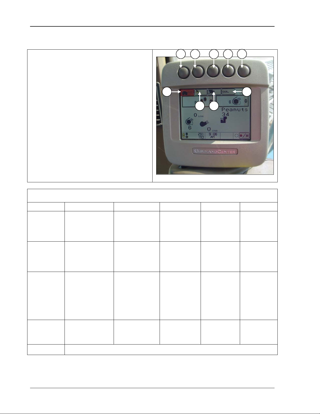
CommandCenter Display 9980 Self-Propelled Peanut Combine
CommandCenter
nformation to view or change. The
s the
number of available pages within that
information type is
button again to advance
Each page of display is described beginning
Button
PAGE 1
PAGE 2
PAGE 3
PAGE 4
PAGE 5
A
View Harvest
settings
Viewable
Not used
Not used
Not used
B
View and zero
weight
Set: Threshing
settings
D
Calibration
C B A D A D C B E
Press button (A, B, C, or D) to select desired
type of i
corresponding icon (A, B, C, or D) on the
display screen is highlighted and show
selection. Once the
selected, press the
through each available page.
on page 88.
Display Navigation
Home
Harvesting
Monitor
C
Setup Pages
Diagnostics
and
Monitor
information, crop
and machine
View yield, select
and change cut
width
speed,
Cleaning fan
damper position,
cleaning fan
speed
Setpoint/automatic
machine settings
(six reconfigure
values of fuel
area/distance,
Active alarms Calibrations
windows)
use,
Not used
View and
change field
totals
Set: Header
width, change
in header
width, record
stop height
Diagnostic
readings
View and
change crop
totals
Not used Not used
Special test Not used
Not used
E Not currently used.
84 09/04/15 MAN141
Page 97
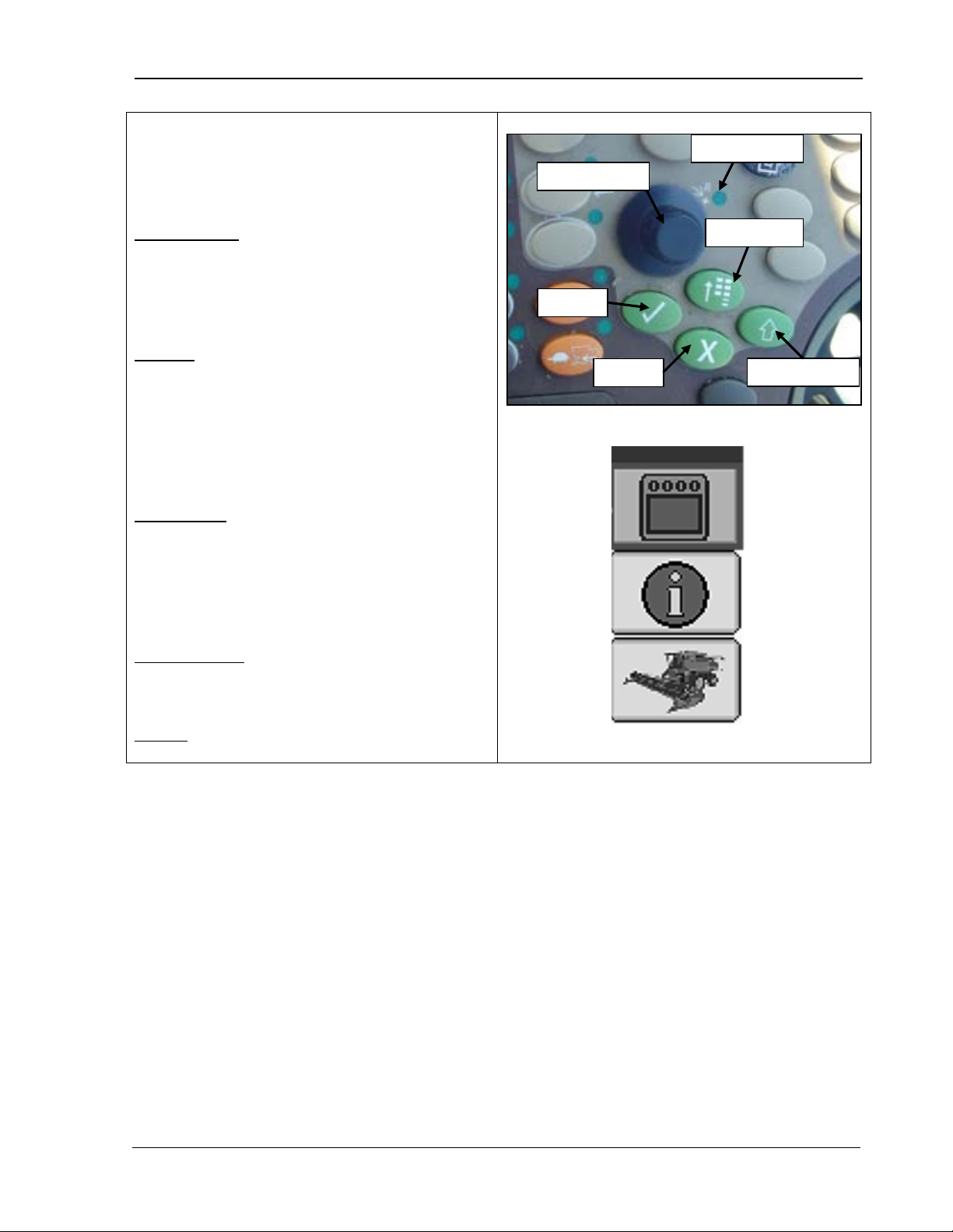
9980 Self-Propelled Peanut Combine CommandCenter Display
Display Controls
Once you have selected a CommandCenter
display page, move through the display as
Scroll through the available items on the
Increase or decrease the values in a
: Once you have used the selection
Toggle between available selections
: Press to change the active
Selection Dial
Main Menu
Confirm
Display Select
Cancel
Indicator Light
follows:
Selection Dial: Rotate the dial to:
•
selected page.
•
selected item.
Confirm
dial to highlight an item on the display, press
Confirm to:
• Select t hat item.
•
within that item.
• Enter /save a value.
Main Menu
application that the display is running. Items
or applications in the menu include:
• Combine
• On Board Diagnostics Tool (OBDT)
• Display Settings
Display Select: Press to toggle Selection Dial
control between the CommandCenter display
or the GreenStar display (if equipped).
Cancel: Press to cancel a current selection.
MAN141 09/04/15 85
Page 98
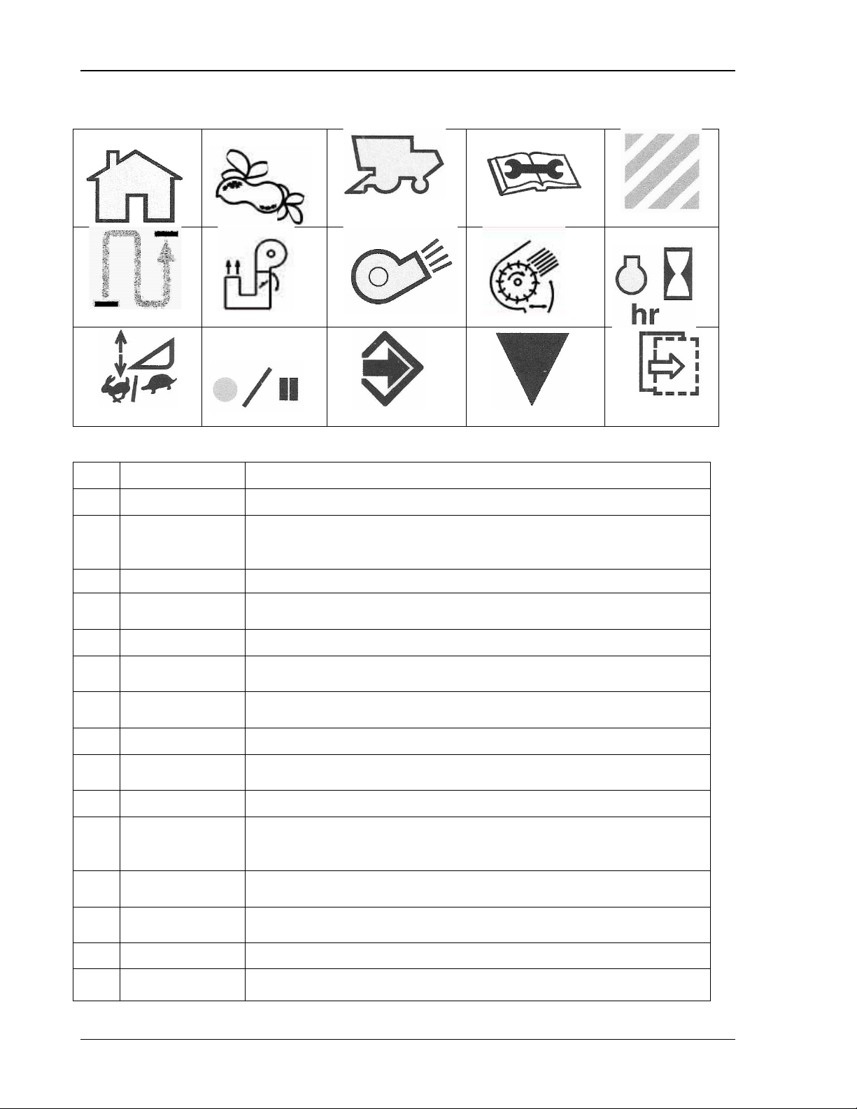
CommandCenter Display 9980 Self-Propelled Peanut Combine
1 2
10
12
Displays current harvest monitor information,
desired settings.
Diagnostics and
Calibration
Displays machine calibrations, diagnostic readings templates and
special tests (templates).
Distance
Harvested
Elevator Fan
Damper
Cleaning Fan
Damper
Header Height
Sensitivity
Recording
ON/OFF
Allows the operator to enter or accept the desired information or
settings.
Display Icons
3 4
6
11
Icon Name Function
1 Home Displays curr ent machine settings previously set by operator.
Harvesting
2
Information
3 Setup Displays current machine settings and current header width.
4
7
performance/productivity, totals, and allows operator to adjust
8
13 14
9
5
15
5 Area Harvested Displays the amount of area harvested.
6
7
8 Cleaning Fan Displays current fan speed
9
10 Engine Hours Displays current rate.
11
Rate and
12
13 Enter/Accept
14 Calibrate Allows the operator to calibrate certain features.
15 Next Step Allows the operator view the next page of information.
Displays total distance traveled for current active load.
Displays position of elevator fan damper.
Displays position of cleaning fan damper door.
Displays current rate and sensitivity settings.
Displays if the recording is on or off.
86 09/04/15 MAN141
Page 99
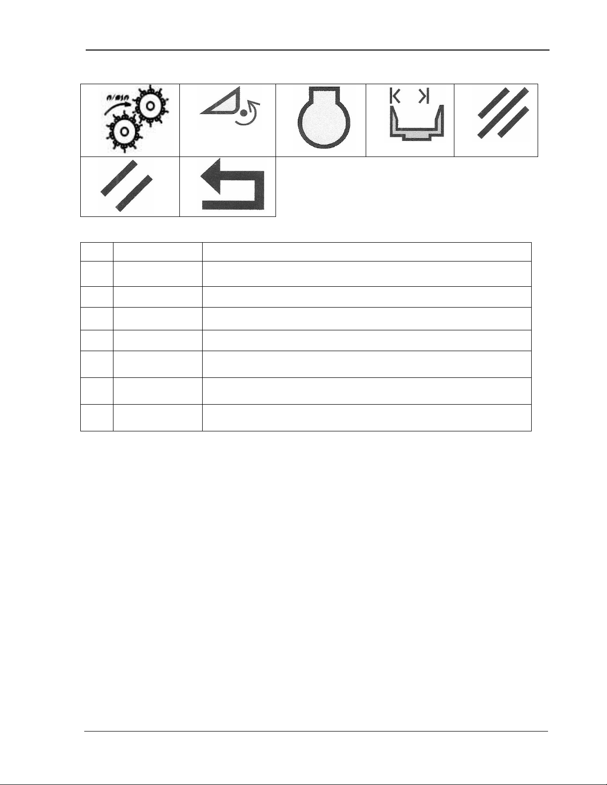
9980 Self-Propelled Peanut Combine CommandCenter Display
16
21
22
Threshing
Speed
17
18
19
20
Icon Name Function
16
Displays the speed of the rear two threshing cylinders.
17 Header Speed Displays the current header speed.
18 Engine Speed Displays the current engine speed.
19 Header Width Displays the current header width position.
20 Cancel Allo ws t h e oper ator to cancel desired information or settings.
21 Clear Allows the operator to clear desired information or settings.
22 Return/Back Allows the operator to view the previous page.
MAN141 09/04/15 87
Page 100
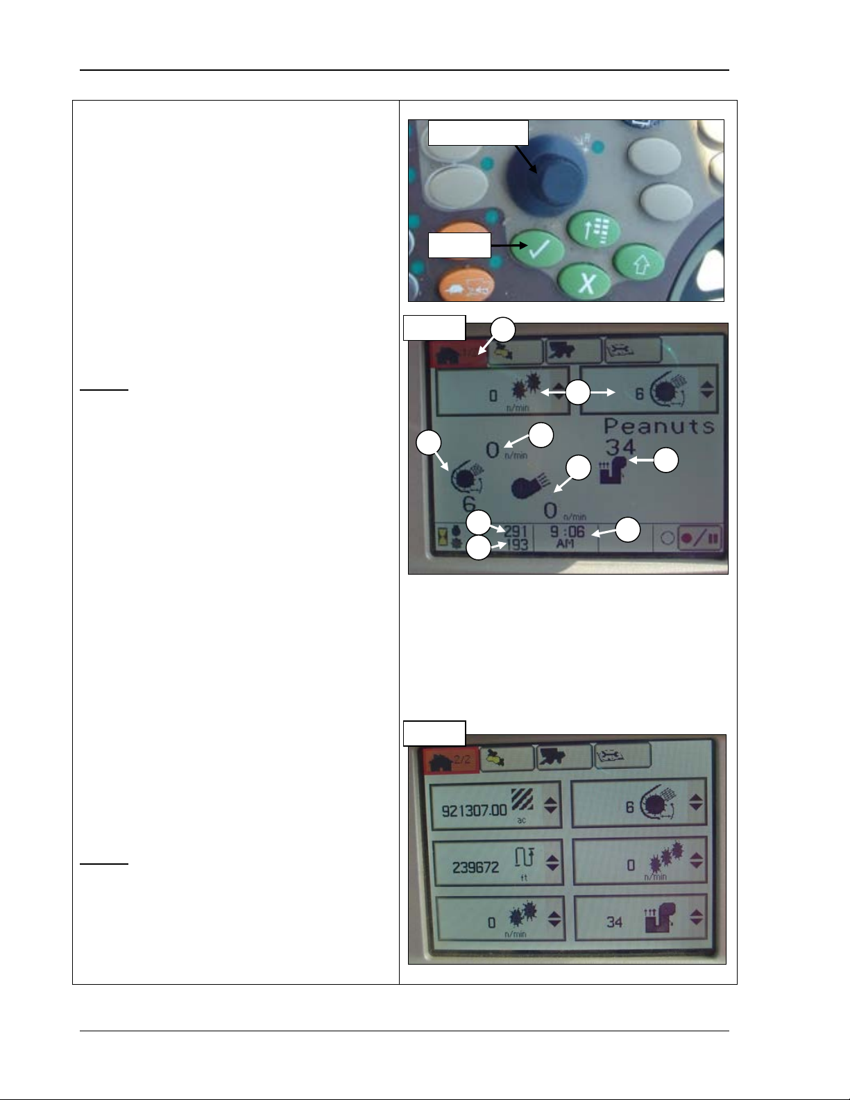
CommandCenter Display 9980 Self-Propelled Peanut Combine
Home Pages
The home pages provide you with current
about your machine. Certain
CommandCenter to display the page in
: you can
“Select Machine Readings to Display” on
that the
always TWICE the actual speed of the
This page displays the machine readings in
A – Home page icon
B
C
D
E
damper speed
F- Elevator fan
Selection Dial
Confirm
Page 1
B C D E F A G H I
Page 2
information
fields allow you to select which items to view.
1. Rotate the Selection dial (top photo) until
the Home Page icon (A) is highlighted.
Or, press the first button at the top of the
the example.
2. Press Confirm (top photo). The first home
page screen displays as in the example.
Page 1
A – Home page icon
B – Selectable machine readings
select which machine readings to display (see
page 89).
C – Threshing speed: NOTE
threshing speed RPM number displayed is
cylinder.
D – Cleaning fan damper position
E – Cleaning fan speed
F – Elevator fan damper position
G – Engine hours
H – Threshing hours
I – Current time: this can be set in standard
or military time
Page 2
– Machine readings
– Threshing speed
– Cleaning fan
damper position
– Cleaning fan
damper position
G – Engine hours
H – Threshing hours
I – Current time
the order you select, allowing you to monitor
six machine functions at a time.
88 09/04/15 MAN141
 Loading...