


STREAK 1000 OCTOCOPTER
Instruction Manual
1

Contents
1. Safety Notes........................................................................................................................................................3
2. Check List............................................................................................................................................................4
3. Equipment Required For Assembly....................................................................................................................6
4 Assembly Steps – Motor and ESC Soldering.......................................................................................................7
5.0 Assembly Steps – Body.....................................................................................................................................8
5.1 Assembly Steps – FPV and GPS Mount..........................................................................................................14
5.2 Assembly Steps - Flight direction indicator....................................................................................................15
5.3 Assembly Steps – Motors and Props...............................................................................................................16
5.4 Assembly Steps – Bipod Landing Gear...........................................................................................................18
5.5 Assembly Steps –
Multicopter Controller Mounting Illustration.......................................................................................................20
6. Quick Collapsible Illustration...........................................................................................................................21
7. Gimbal Mounting Illistration.............................................................................................................................23
8. Specification......................................................................................................................................................24
End Of Manual......................................................................................................................................................25
2

1. Safety Notes
Do fly only in safe areas and always away from other people! Do not operate RC aircraft within the
vicinity of homes or crowds of people. RC machine are prone to accidents, failures, and crashes due
to a variety of reasons including pilot error, radio interference, and lack of maintenance. Pilot are
responsible for their actions and damage or injury occuring during the operation of RC aircraft
machine.
When flying the aicraft, the fast rotating props of Streak 1000 may cause serious injuries with any
accident occurred. Therefore please keep in mind that safety at first during the flight.
The ONLY Flying direction suitable for Streak 1000:
Make sure you have installed your own Hexacopter Controller and the Props in the correct direction
according to the factory's manual of the Controller.
3
2. Check List
Please Check the Follow parts.
Apc Propeller 14x4.7SFP (CW)
4 Pcs
Apc Propeller 14x4.7SFP
(CCW) 4 Pcs
Large Current Power/ESC
Board (Black/ Blue
color) with 2 pairs Battery Cable.
Servo Extension Wire ( 30cm )
8 pcs
AWG wire Red ( 45cm )
8 pcs
AWG wire Black ( 45cm )
8 pcs
1pcs x Direction Indicating
Sticker
Alware Brushless Motor 351515 KV400 (Not included unless
otherwise specified.) 6 Set
Screw set come with Motor.
6 Set
4
Battery Support Damper 8pcs Spare Screw Pack 1pcs
Frame Parts:
Main Frame Assembly
1 set
FPV & GPS Mounting Assembly
1Pcs (left)
Landing Gear Frame Assembly
1 Pcs (right)
Motor Mount with Quick Lock
Mount Assembly
4 sets
Motor Mount with Fixed Arm
Assembly
4 sets
Leading Gear Assembly
2 sets
Landing Gear Skid (420 mm)
2 pcs
5
3. Equipment Required For Assembly
40A ESC(6S 22.2V) (e.g.
HobbyWing FlyFun 40A ESC)
8 pcs
3.5mm Bullet Connector
(Female) for 8pcs ESC
24 pcs
“V” Mode OctCopter Controller
(e.g. DJI WK-M)
1 pcs
Connectors For Batteries and
Power Board
2 pairs
Transmitter (7CH or above)
1 pcs
Receiver (7Ch or above)
1 pcs
6S Lipo Charger
1pcs
6S LiPo Battery 3500-7500mAh
22.2V ( Will be connected in
Parallel)
2pcs
6
4 Assembly Steps – Motor and ESC Soldering
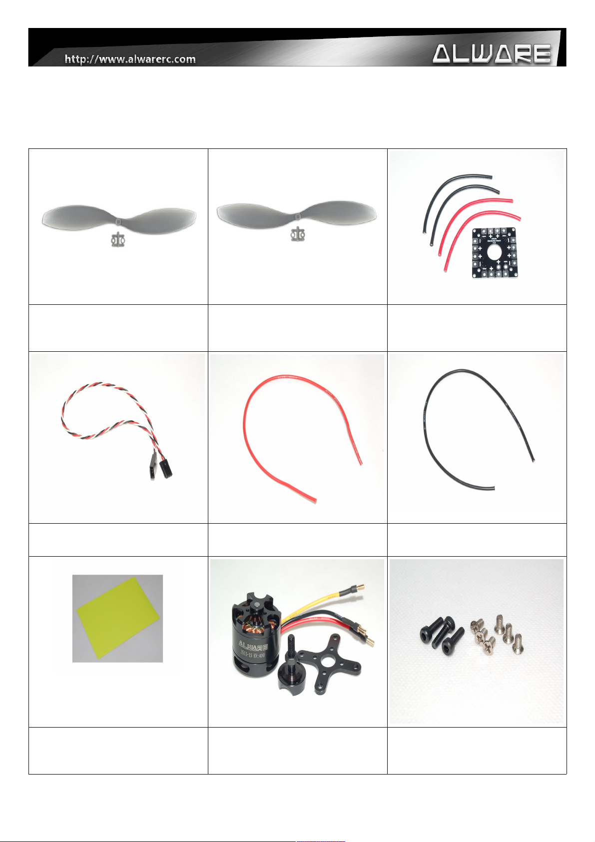
Step 1.
You will received 8 motors in ALS1000CB.
Step 2.
For the new motors, Thread Lock must be applied to
the two M3 Set Screws which is pre-inserted in the
motor.
(This is a must for safety flying.)
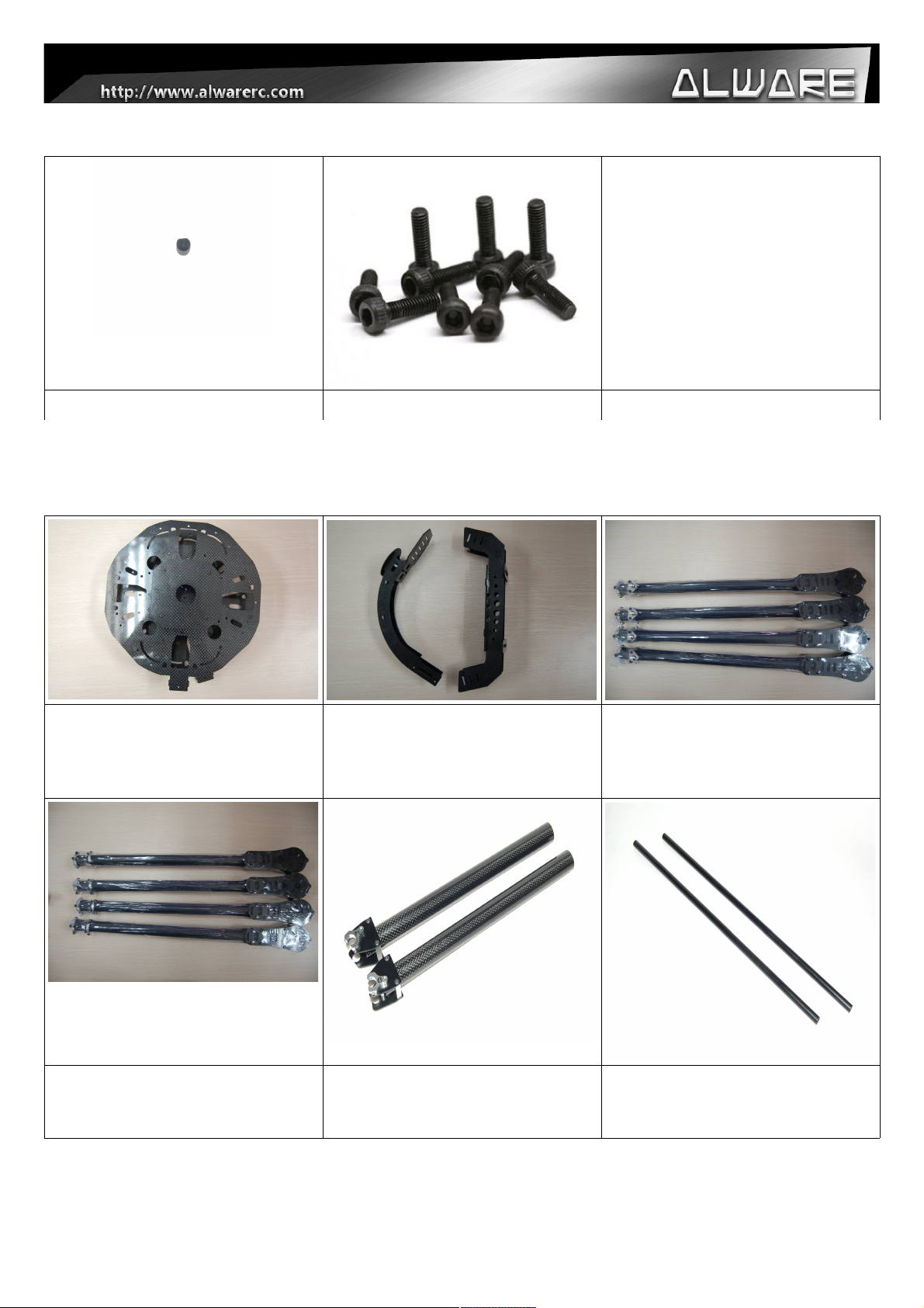
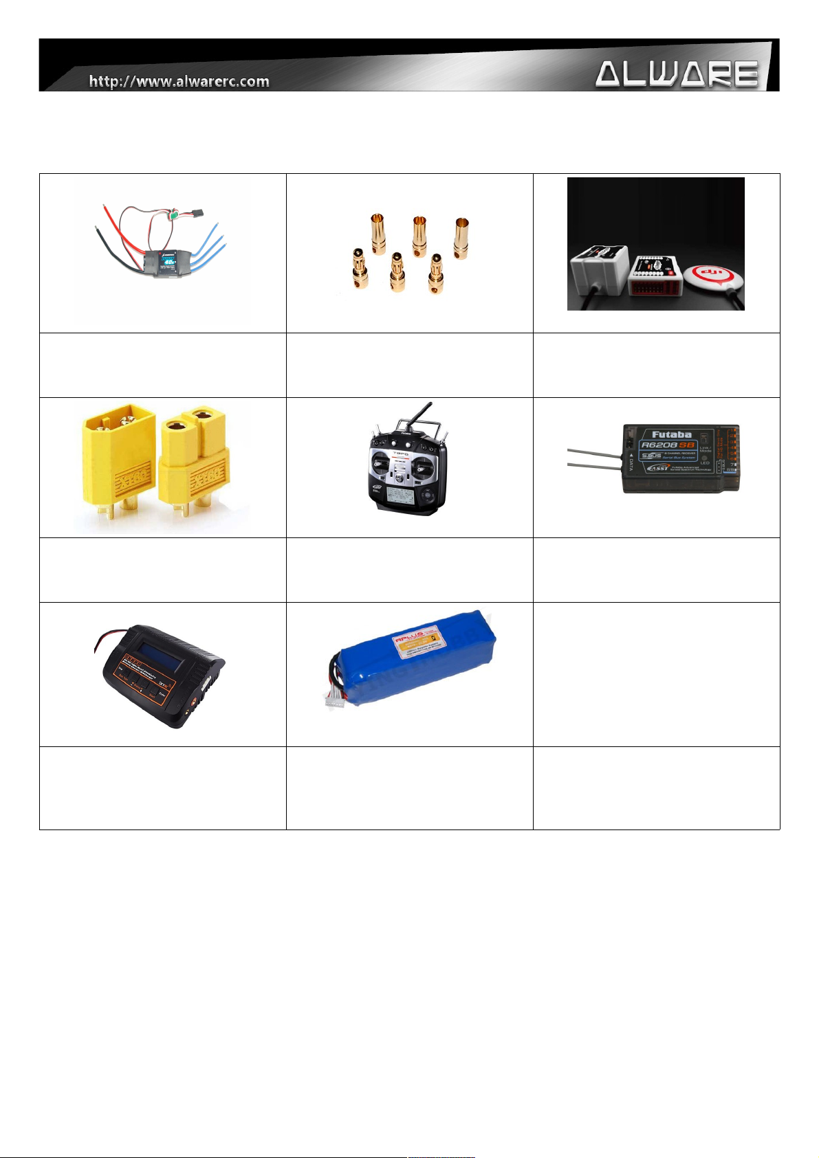
Step 3.
Install the Porp Mount to the motor using 3pcs M3
Hex Cap Screw. (Apply little amount of Thread Locker
when assembly metal to metal parts.)
Step 4.
Double check the prop mount which must be installed
to the motor securely.
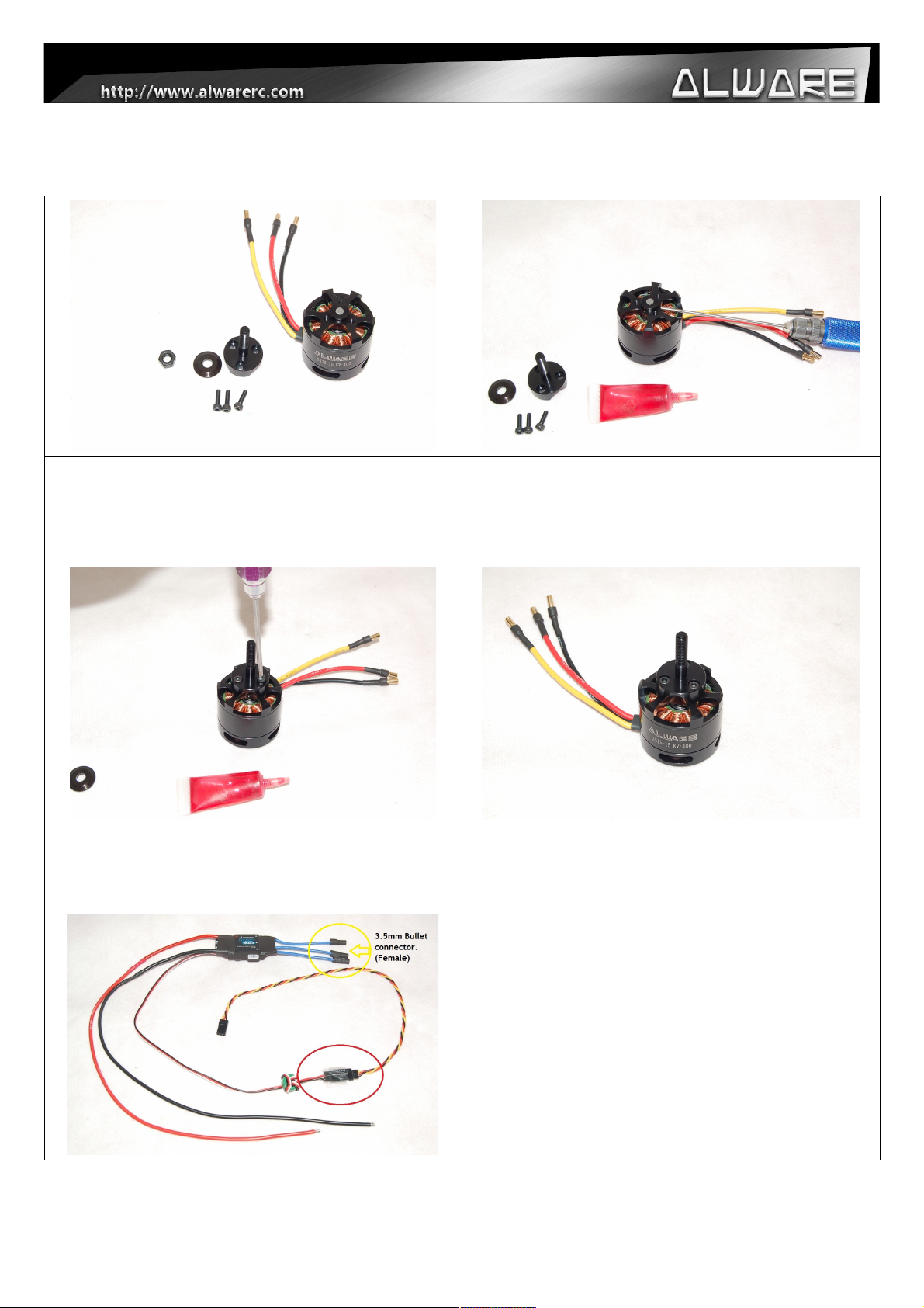
1.) Solder Black and Red AWG wires to the ESC.
2.) Solder 3pcs 3.5mm Bullet Connectors (Female) to
the ESC.
3.) Connect Servo Extension Wire to the Signal
Connector of ESC and secure it using Adhesive Tape.
7
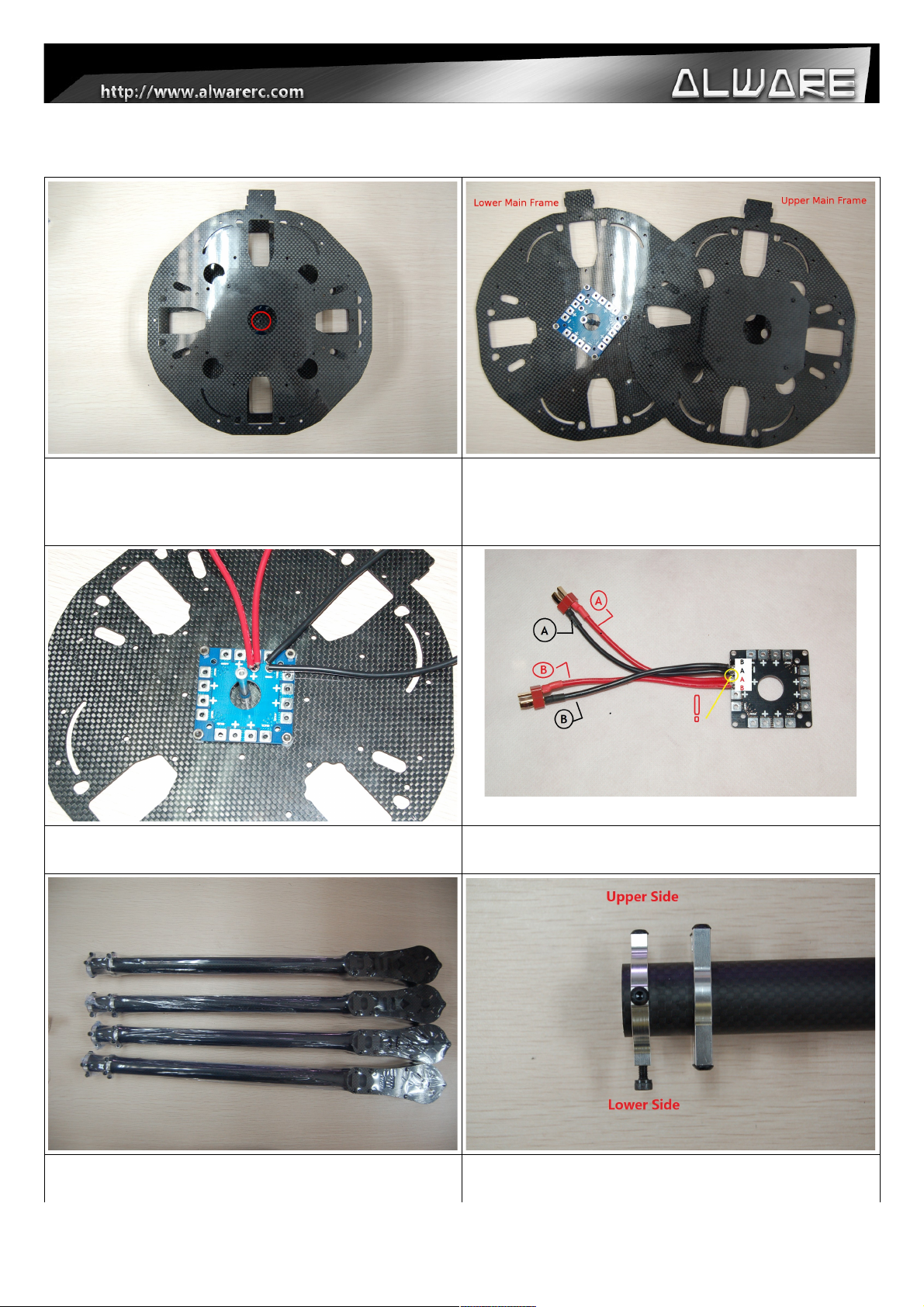
5.0 Assembly Steps – Body
Step 1.
Loosen the screw circled above as to uninstall the
Upper Main frame from the Main Frame Assembly.
Step 2.
Lower Main Frame with Power/ESC Board
preinstalled (on the left) and the Upper Main Frame
(on the right).
Step 3.
Solder 2 pairs Battery Cable to the Power.ESC Board.
Step 4.
Close view of step 3 soldering.
Step 5.
Prepare four Motor Mount with Fixed Arm Assembly
Step 6.
Close view of Motor Mount with Fixed Arm Assembly.
8

Step 7.
Loosen the screws of the Lower side. The Hook Side
must pointing to the Axis Line of the Lower Main
Frame for installation.
Step 8.
Install the Motor Mount with Fixed Arm Assembly onto
the Lower Main Frame. Follow the installation
direction as shown above. (Apply little amount of
Thread Locker to the screws before installation.)
Step 9.
Install four Motor Mount with Fixed Arm Assembly
onto the specific position of Lower Main Frame.
Step 10.
Reserve the above four screw holes for the Landing
Gear installation in the later steps.
Step 11.
Prepare four Motor Mount with Quick Lock Mount
Assembly.
Step 12.
Close view of Motor Mount with Quick Lock Mount
Assembly.
9

Step 13.
Loosen the screws and Quick Lock Mount of the
Lower side. The Hook Side must pointing to the Axis
Line of the Lower Main Frame for installation.
Step 14.
Install the Motor Mount with Quick Lock Mount
Assembly onto the Lower Main Frame. Follow the
installation direction as shown above. (Apply little
amount of Thread Locker to the screws before
installation.)
Step 15.
Secure Quick Lock Mount using M3x8mm Screws.
(Apply little amount of Thread Locker to the screws
before installation.)
Step 16.
Repeat step 13-15 to secure other three Motor Mount
with Quick Lock Mount Assembly onto the Lower Main
Frame.
10
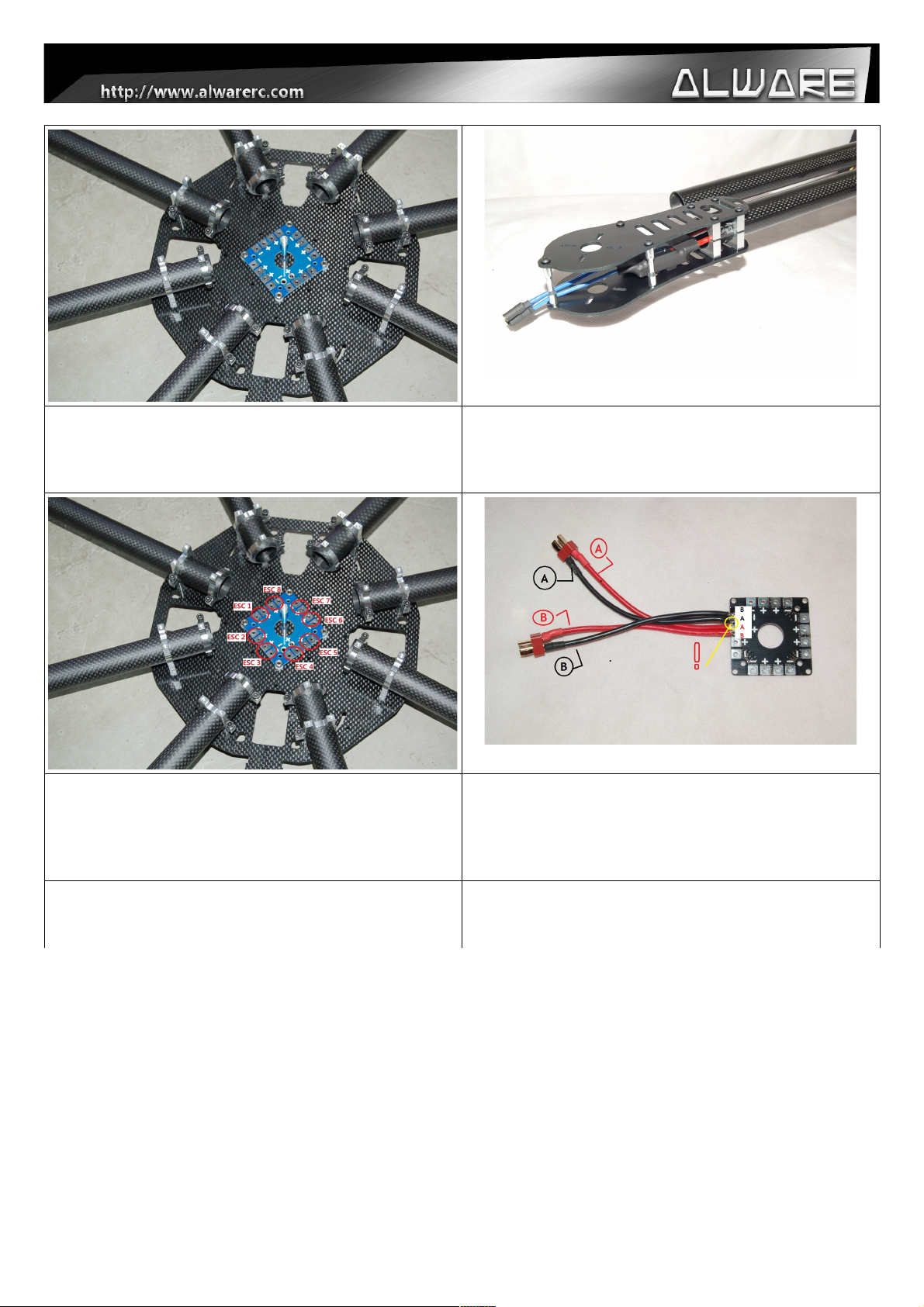
Step 17.
Close view of the Motor Mount Assembly Installation
on the Lower Main Frame. Make sure the installation
is same as above.
Step 18.
Insert the Battery Power Cable and Signal Wire of the
ESC into the Carbon Boom Arm. Same for all 8pcs
ESCs.
Step 19.
Solder the Battery Power Wires of the ESC to the
ESC Board. (Red wire = +ve , Black wire = -ve)
Step 20.
Solder 2 pairs Battery Cable to the Large Current
Power/ESC Board and connect the other end to the
Battery Connectors. (Red = +ve , Black = -ve) Do not
short circuit two polarities!!
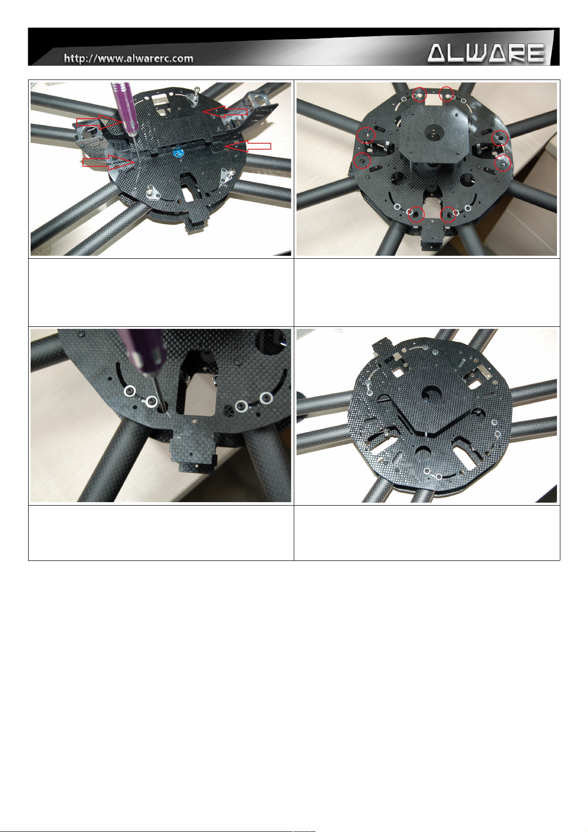
11

Step 21.
Install the Upper Main Frame onto the Lower Main
Frame Assembly. Secure the screws for the four
Motor Mount with Fixed Arm Assembly first. (Apply
little amount of Thread Locker to the screws before
installation.)
Step 22.
Secure the screws with 3mm Washer for the four
Motor Mount with Fixed Arm Assembly. (Apply little
amount of Thread Locker to the screws before
installation.)
Step 23.
(Apply little amount of Thread Locker to the screws
before installation.)
12
Step 21.
Install the Landing Gear Frame Assembly onto the
Lower Main Frame using M3x10mm Screws from step
7. (Apply little amount of Thread Locker to the screws
before installation.)
Step 22.
Secure the Booms.
Step 23.
Secure the all Booms using the pre-installed M3
screws on the Motor Mount Assemblies. (Make sure
all 8 Booms are completely secured.)
Step 24.
Perform Part 6. Quick Collapsible Illustration
shown bellow as to check the folding mechanism of
for arms.
13

5.1 Assembly Steps – FPV and GPS Mount
Step 1.
Prepare the FPV & GPS Mounting Assembly.
Step 2.
Get ready for the installation of FPV & GPS Mounting
Assembly onto Main Body.
Step 3.
Insert the FPV & GPS Mounting Assembly onto Main
Body Rib and secure with M2x6mm Hex Cap Screws.
(Apply little amount of Thread Locker to the screws
before installation.)
Step 4.
Indicate the forward flying direction.
14
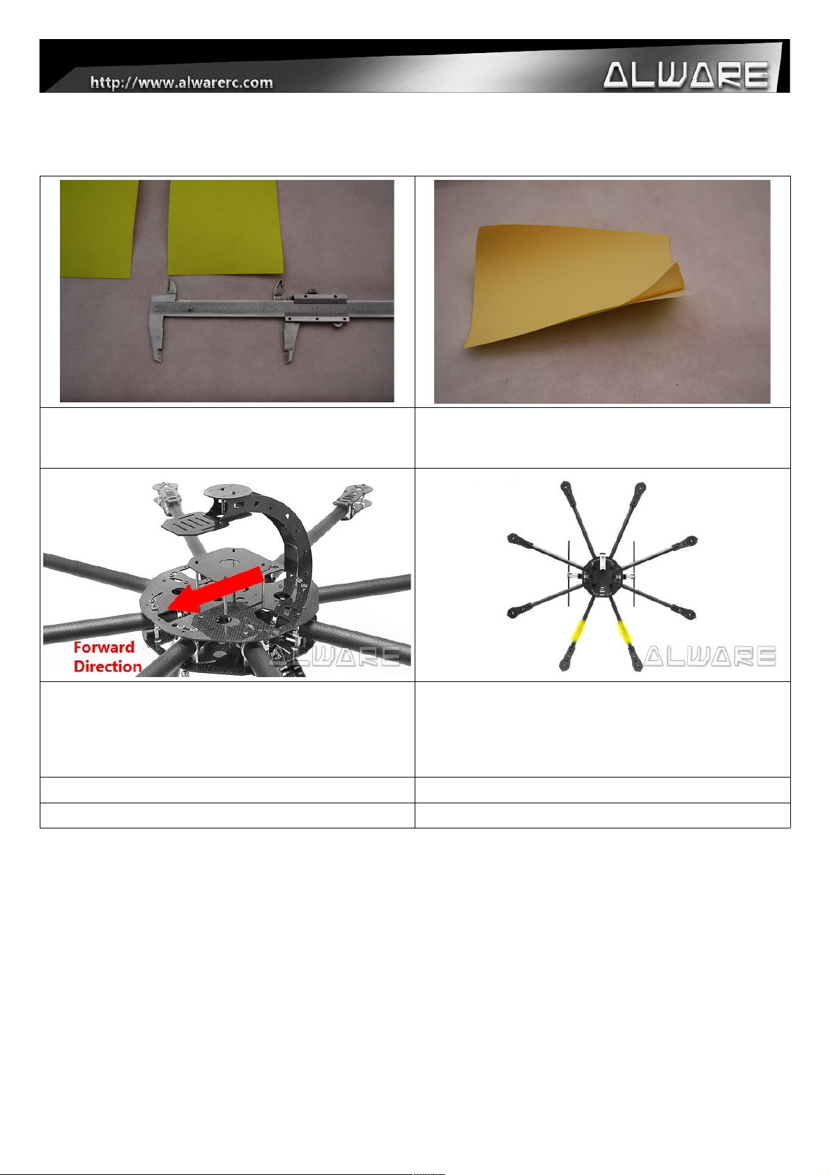
5.2 Assembly Steps - Flight direction indicator
Step 1.
Cut the Direction Indicating Sticker with a width of
around 100mm.
Step 2.
Tear the cover layer of the Sticker before stick to the
front Carbon Arm Boom.
Step 3.
Indicate the forward flying direction.
Step 4.
Stick the Direction Indicating Sticker (100mm Width)
to the two Carbon Arm Boom in the forward flying
firection. And use three pieces of Adhesive Tape to
secure the Direction Indicating Sticker.
15
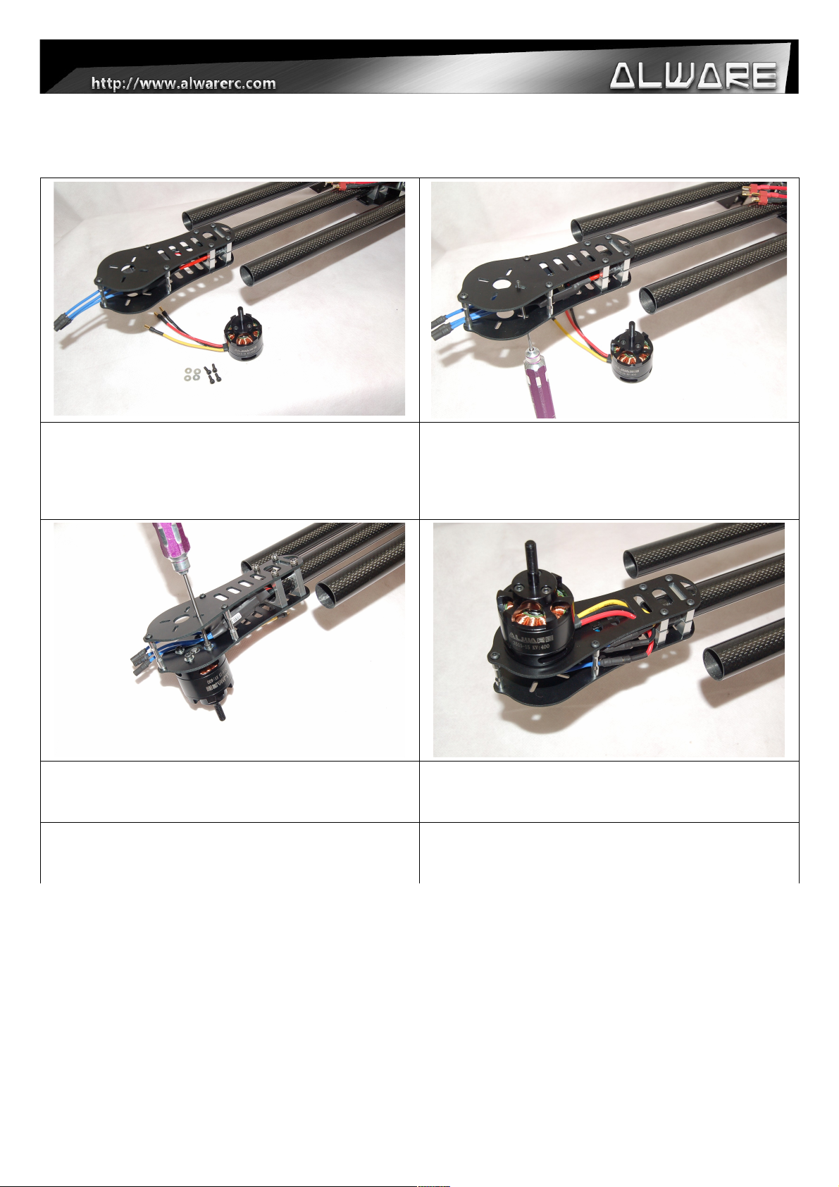
5.3 Assembly Steps – Motors and Props
Step 1.
Prepare 4pcs M3x8mm HexCap Screws with 4pcs
3mm Washers to install the motors to the Motor
Mounts.
Step 2.
Insert a M3x8mm Screw into a 3mm Washer then
insert to the motor mount slot as to mount the Motor
to it. (Apply little amount of Thread Locker when
assembly metal to metal parts.)
Step 3.
Secure the motor to the motor mount with 4pcs
screws and washers.
Step 4.
Insert the Motor Wires into the slot of motor mount
and connect with motors.
16
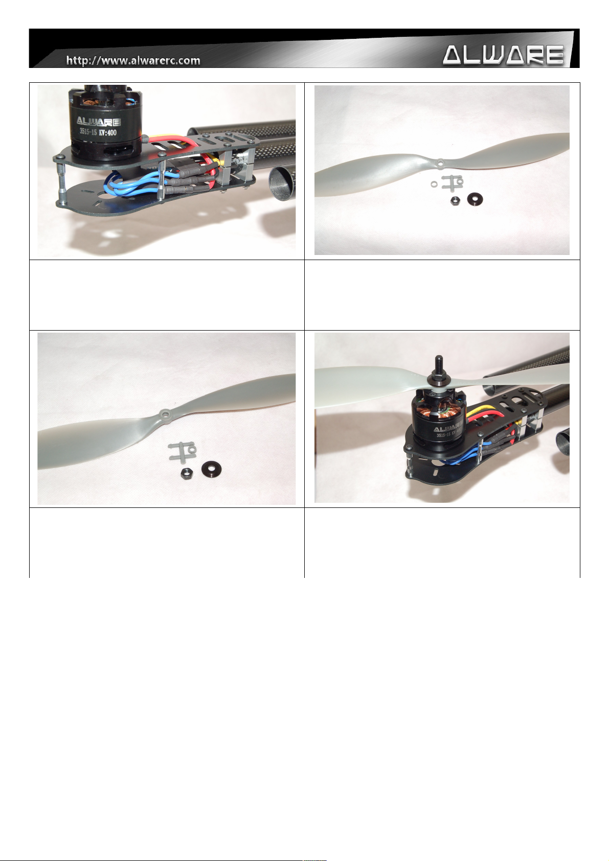
Step 5.
Repeat Step 1 to 4 for other 7 motors. Test the motor
first without propellers as to ensure the rotating
direction is correct. Exchange any two motor wires to
the ESC as to reverse the direction if needed.
Step 6.
After ensuring the motors are running in the correct
direction, prepare the APC Props and Prop mounting
screw and washer from the motors.
Step 7.
Insert the Root Hole Adapter (with 6mm inner
diameter) to the bottom side of APC Prop.
Step 8.
Install the Propeller to the motors and secure it with
Prop mount Screw and Washer. (Please refer to your
Multicopter Controller Manual to install the CCW &
CW Props in the correct direction.)
17
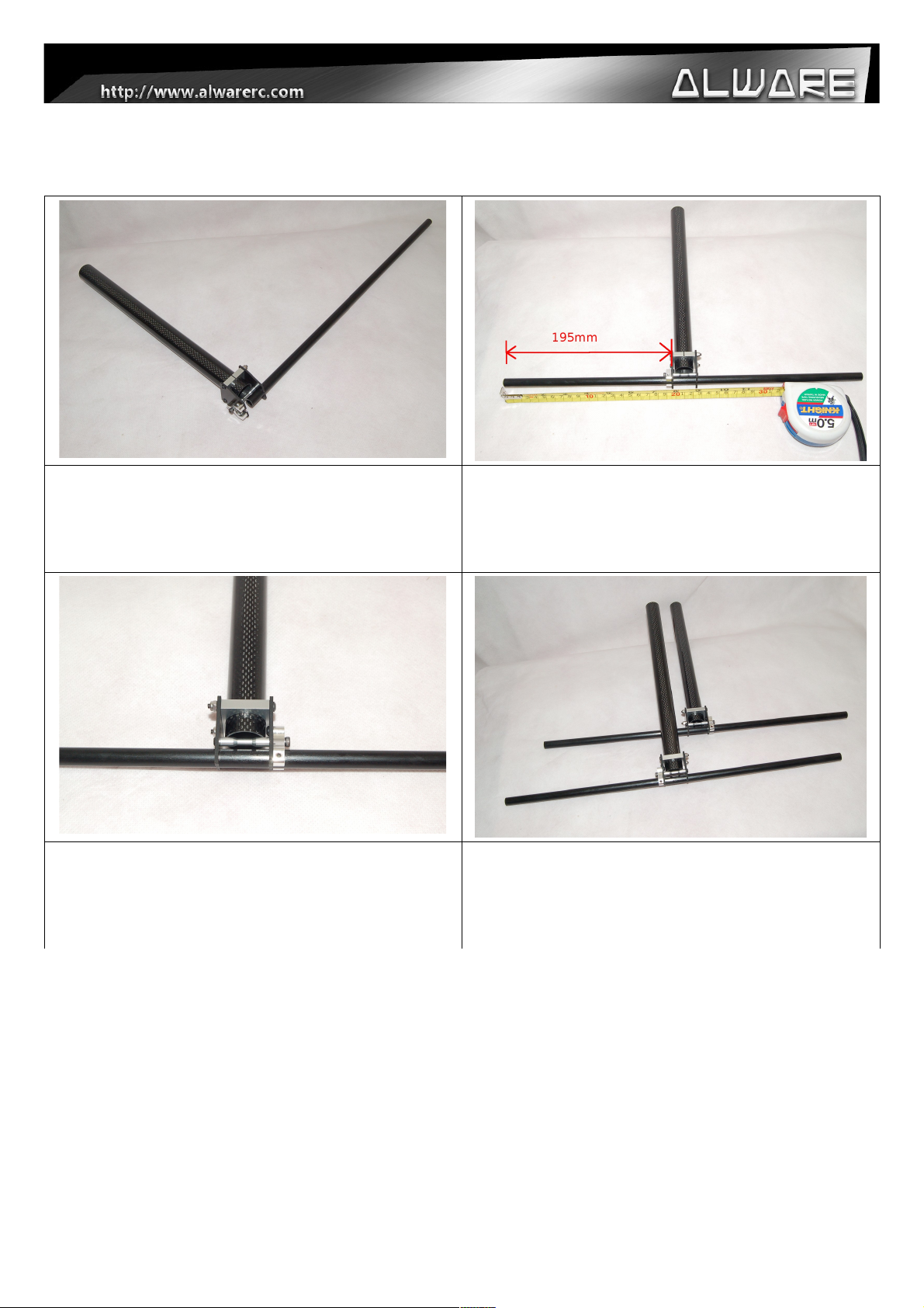
5.4 Assembly Steps – Bipod Landing Gear.
Step 1.
Insert the Landing Gear Skid into the mounting hole of
Carbon Fiber Leading Gear Assembly. (Tips: You can
rotate the Landing Gear Skid into the hole with less
effort.)
Step 2.
Adjust the length of the Landing Gear Skid. Each side
of the Landing Gear Skid should be about 195mm.
Step 3.
Secure Landing Gear Skid onto the Carbon Fiber
Leading Gear Assembly using the M3 Set Screw
which is pre-installed on the Landing Gear Skid Metal
Mount.
Step 4.
Repeat Step 1-3 to complete another side of Bipod
Landing Gear Assembly. (Remarks: Two set of Bipod
Landing Gear Assemblies are not exactly the same
but is in symmetry direction.)
18

Step 5.
Correct two Bipod Landing Gear Assemblies.
Step 6.
Insert the Carbon Boom of Bipod Landing Gear
Assembly into the metal mount of Landing Gear
Frame Assembly with the depth of approximately
5mm.
Step 7.
Adjust the Bipod Landing Gear Assembly to make the
Landing Gear Skid be parallel to the Landing Gear
Frame Assembly frame. And secure the Landing Gear
Frame Assembly with the M3 Screws.
19

5.5 Assembly Steps – Multicopter Controller Mounting Illustration.
Overall electronics mounting for reference. Installation of WK-M, Front View.
Back View. GPS Compass mounting for reference.
20

6. Quick Collapsible Illustration
With the Quick Collapsible Design, you can fold four
arms of Streak 1000 easily for easy transportation
and storage. However you must follow the coming
step by step to fold the arms correctly, otherwise the
Lock System may damaged!
Step 1.
Four Arms of Streak 1000 are locked with four Thumb
Screws with Split Lock Washers.
Lower Main Frame Side
Upper Main Frame Side
Step 2.
Loosen the above Screws a little bit (normally loosen 0.5 turns from complete tighten status), but do not
loosen or tighten completely. Otherwise the Arms will not be foldable. If you found that it is getting loosen
after the flight, secure the screws with Thread Locker again for secure flight. Adjust the tightness of these
screws for the smoothness to fold the arms, loosen it a little bit more if your folding arms are too tight.
21

Step 3.
Loosen the Thumb Screw and make sure it is not
touching the Fiber Frames. Then the four Folding
Arms can be folded or opened.
Step 4.
Make sure the Arm is fully folded or opened, and then
tighten the Thumb Screw completely. It should
throught two layer of the carbon fiber frames as
shown above for secure flying.
Step 5.
Always check if the above four Screws on the Upper
Main Frame are secured tightened completely for
secure flight. If you found that it is getting loosen,
secure it with Thread Locker. At the same time, do
Step 2 shown above from time to time to ensure a
secure flying.
22

7. Gimbal Mounting Illistration
Step 1.
Indicate the Multi-Gimbal Mount which is installed with
Landing Gear Frame Assembly.
Step 2.
Mounting position for GAUI CRANE 3 and CRANE 2
Gimbals.
Lensman series professional Gimbals will be
available soon..
Step 3.
Mounting positions for other Gimbals such as STO S903(3-axis) Gimbal, STO Camera Mount Kit S-550 etc.
23

8. Specification
Kit:
-Diagonal Wheelbase: 1030mm
-Motor Mounting Frame Size: Φ13x22-34mm(Shaft x Screw Diagonal Distance)
-Bipod Landing Gear Dimension:
188mm(Top Width) x 466mm(Lower Width) x 348mm(Height)
-Landing Skid Pipe: Φ10x420mm
-Bipod Landing Gear Weight: 136g
-Total Kit Weight: 1400g (Approx.)(Without Electronics & Props)
-Total Weight with Motors, Props, 40A ESCs, WK-M: 3.5kg
Carbon Arm Booms:
-Length: 380mm
-Weight: 35.7g
-Thickness: 1mm
-Diameter: 22mm
-3K Matt Surface
Propeller:
-Manufacturer: APC PROPELLERS in USA
-Size: 14×4.7 Inch
-Root Hole Diameter: 5-6mm
-Center hub thickness: 6mm
-Weight: 25.3g/pcs
Motor:
-Model: Alware Multicopter Brushless Motor 3515-15
-KV value: 400KV
-Stator Diameter: Φ35mm
-Stator Length: 15mm
-Propellwe Mount Diameter: 6mm
-Motor Dimension: Φ42.5x35mm
-Weight: 178g (with 3.5mm Bullet Connectors and Prop Mount)
24

-Input voltage: 22.2V 6S LiPo Battery
-Max continuous current: 35A(180sec)
-Max output power: 750W(180sec)
-Internal resistance: 175mOHM
-Recommended ESC: HobbyWing 40A/ 60A
Speed Controller/ ESC:
-Current: 40A or Above
-Voltage: 22.2V 6S LiPo
-Largest Dimension: 30x80x25mm (WxLxH)
-Recommended ESC: HobbyWing 40A ESC(for 22.2V 6S Lipo)
# Report any mistakes, please email to: info@alwarerc.com
Related Videos could be found on: http://www.youtube.com/watch?v=ucpmYxhgJw0
End Of Manual
25
 Loading...