

Page 1
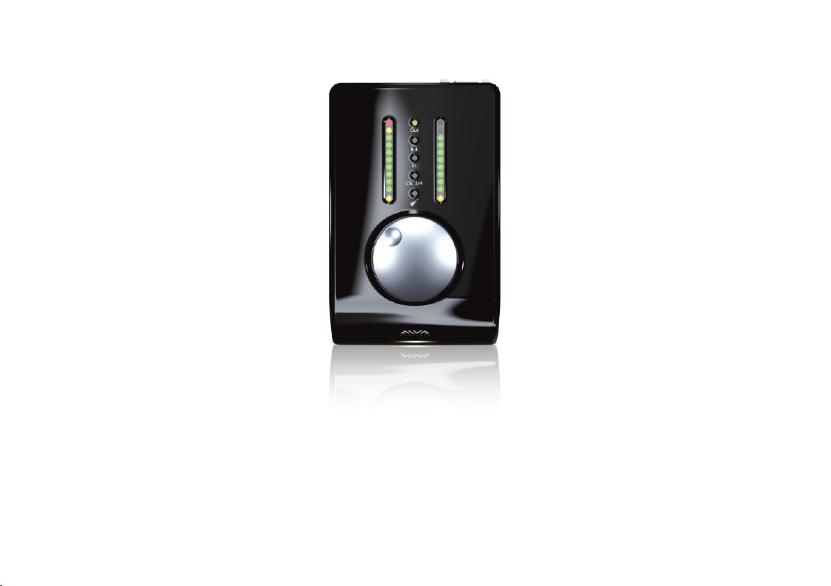
Nanoface
User manual
Page 2

ContentsDisclaimer
The information contained within this manual is solely advisory.
ALVA is not responsible for actions you may take without proper advice. You should not rely on this information as absolute and are
responsible for understanding the given information. You should not rely on this information as absolute. If you do act upon the suggestions
contained in this document, you are fully responsible for yourself and your actions.
Should the information in the Nanoface manual prove to be false, misleading, or in contravention to law, statute, or regulation, you assume
all risks.
ALVA does not accept responsibility for any loss, damage or expense resulting from the use of this information contained in the manual, even
if the information was false, misleading, or in contravention to law, statute, or regulation.
Please send feedback, comments and corrections to [email protected]
The Nanoface manual © 2012 ALVA. All rights reserved.
All Nanoface features and specifications are subject to change without notice.
Mac OS X is a trademark of Apple Inc.
CoreAudio is a trademark of Apple Computer, Inc.
Microsoft, Windows XP, Windows Vista, Windows 7 are trademarks of Microsoft Corp.
Alesis and ADAT are registered trademarks of Alesis Corp.
Steinberg, Cubase and VST are registered trademarks of Steinberg Media Technologies GmbH.
ASIO is a trademark of Steinberg Media Technologies GmbH.
Other trademarks are the property of their respective owners.
4 What is the Nanoface?
6 Quick Info Cable connectors . Encoder operation overview . Peakmeters
12 Getting started Connection . Driver Installation
18 Using the Nanoface Encoder operations
28 Connecting equipment Outputs
37 Connecting equipment Inputs
2 3
Page 3
1
What is the Nanoface?
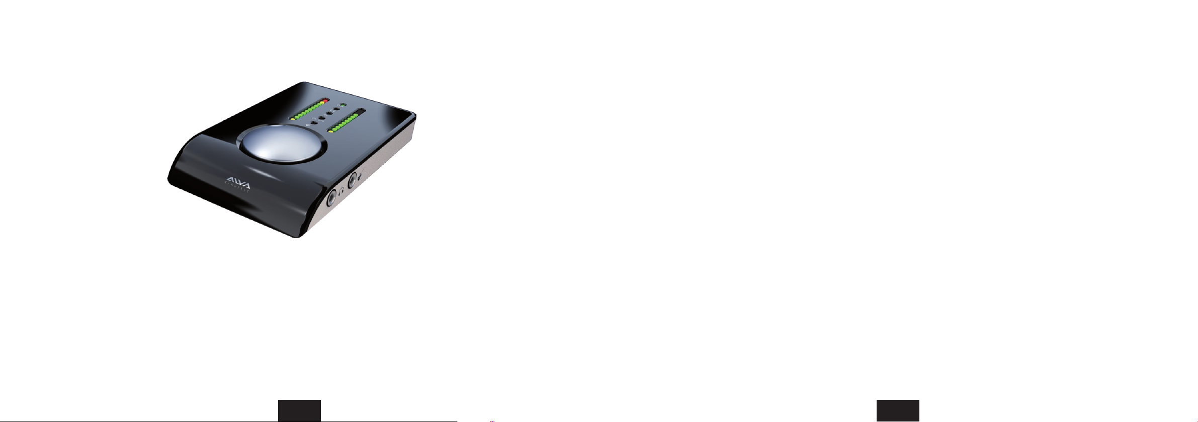
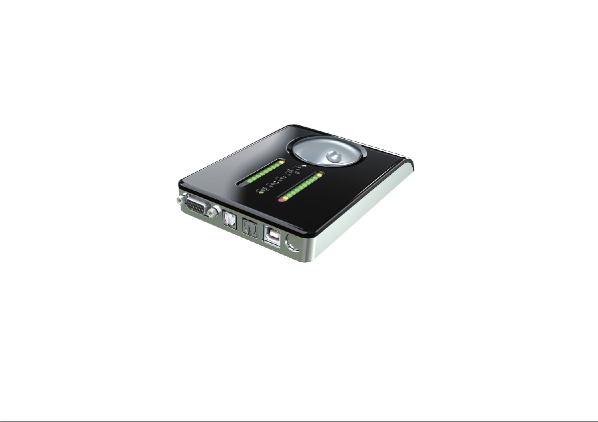
A 12-Channel 96 kHz audio interface with one MIDI input and 2 MIDI outputs?
The Nanoface is a pocket studio. Light as a feather. Easy to operate.
It’s the perfect solution for musicians, DJs or HiFi listeners who need an interface with high-end sound,
great usability, the size and weight of their wallet.
It needs just a simple USB cable to connect to every PC or Mac.
Sure. But there is more:
The Nanoface philosophy: Reduce to the max.
Most interfaces provide a big software package with useful features, but have a steep learning curve and consume the
most important thing a musician doesn’t have. Time. Time to mess with all the technical stuff.
But creativity needs boundaries. In an unlimited space there is no need to be creative, as all destinations can be reached –
with just some knowledge and craftsmanship.
The ALVA designers decided to try another way: Sensible downsizing.
The Nanoface is designed as partner of modern digital audio workstations. There are no software option
dialogs or an integrated mixer. Just a high-speed driver.
All modern audio programs provide a low latency engine, an integrated mixer with plug-in support and monitoring
features. They emulate a complete studio workflow. Some audio interfaces try to do the same and thus doubling not only
the features, but also the time to mess with them.
The Nanoface is dierent. All features can be controlled with ONE multi controller. Directly on the unit. In combination
with an audio sequencer this is what most all musicians need. No more. No less.
If you want to use a mixer, with sends, busses and effects – it’s already in your DAW software.
Concentrate. Be creative.
4 5
Page 4
2
Quick info
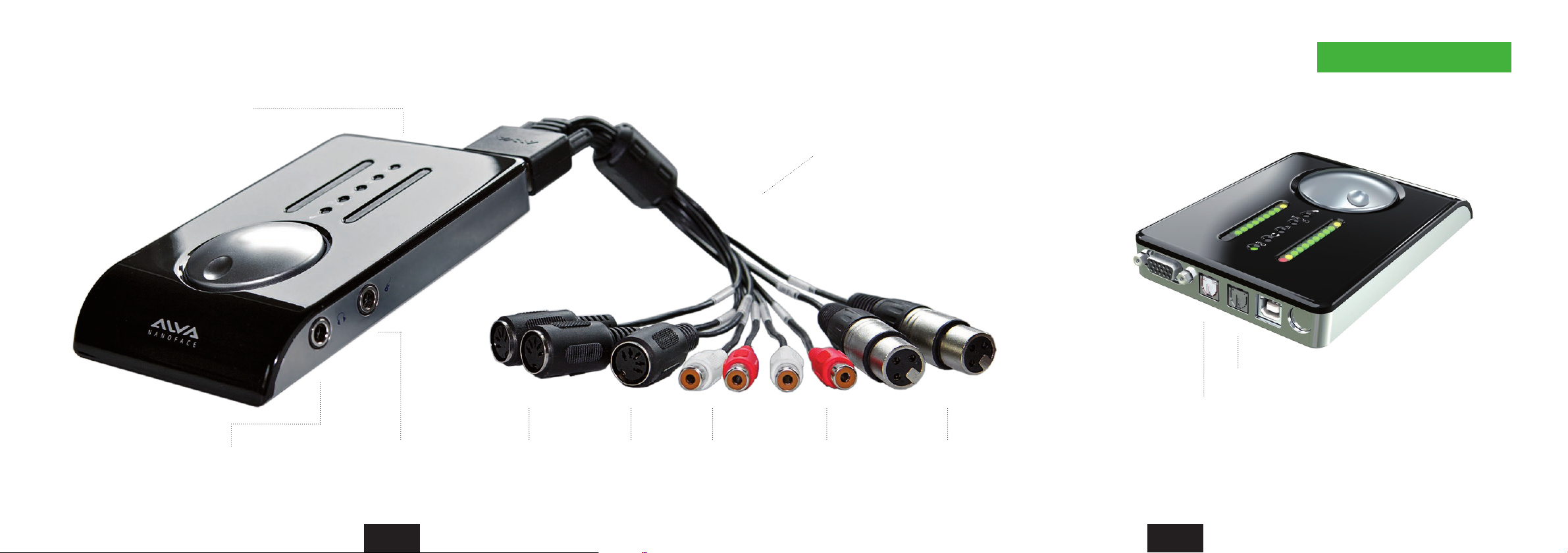
Nanoface connections
Digital S/PDIF I/O (optical)
Phones output
(= Analog output 3+4)
Hi-Z
instrument input
(electric guitar or bass)
2 x MIDI
output
MIDI
input
Analog
outputs 1+2
Breakout cable
Extension cable option available
(1 & 3 m / 3.2 & 9.8 ft.)
Analog
inputs 3+4
Analog inputs 1+2
(2 x mic preamp)
Input
Output
(red light)
Digital S/PDIF I/O (optical)
6 7
Page 5
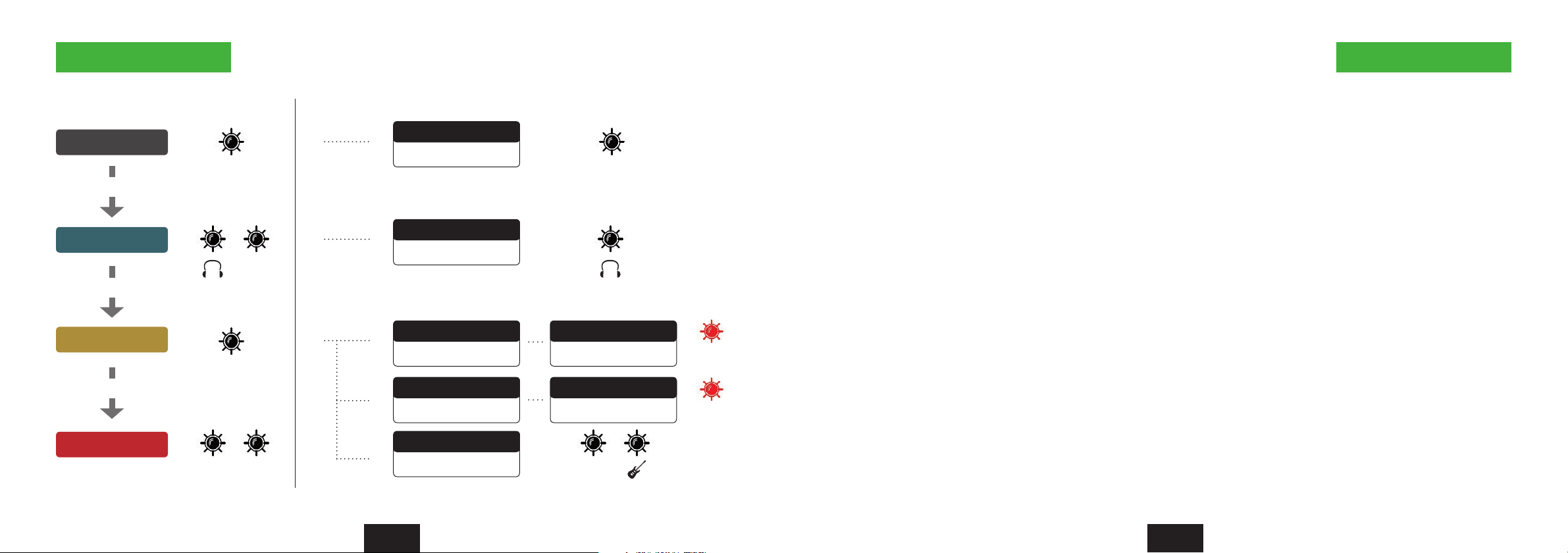
Encoder operations Reset the Nanoface
Mode LEDs on LEDs onAdditional operations
Output 1/2
Press Encoder
Output 3/4
Press Encoder
Input 1/2
Press Encoder
Input 3/4
Monitoring On/Off
Double click
Out Out
Out 1/2 to Phones
Click/hold + Turn left
3/4
Gain Channel 1
Click/hold + Turn left
48V Channel 1
Press 3 sec.
In
Gain Channel 2
Click/hold + Turn right
48V Channel 1
Press 3 sec.
Hi-Z In for Channel 2
In In
3/4
Double Click
1st red LED
Channel 1
1st red LED
Channel 2
The last Nanoface settings are stored in the internal memory.
The Nanoface starts where you left it before a disconnection from the host computer or a restart.
To reset the Nanoface to the default parameters: Click + hold the encoder
during power up (USB re-connection or start of the host computer).
The following parameters will be set:
Output, Phones and input gain: -3.5 dB
Preamps/Hi-Z gain: 0 dB
Phantom Power (48V): off
Phones out to channel 3/4
2 Quick info Quick info 2
8 9
Page 6
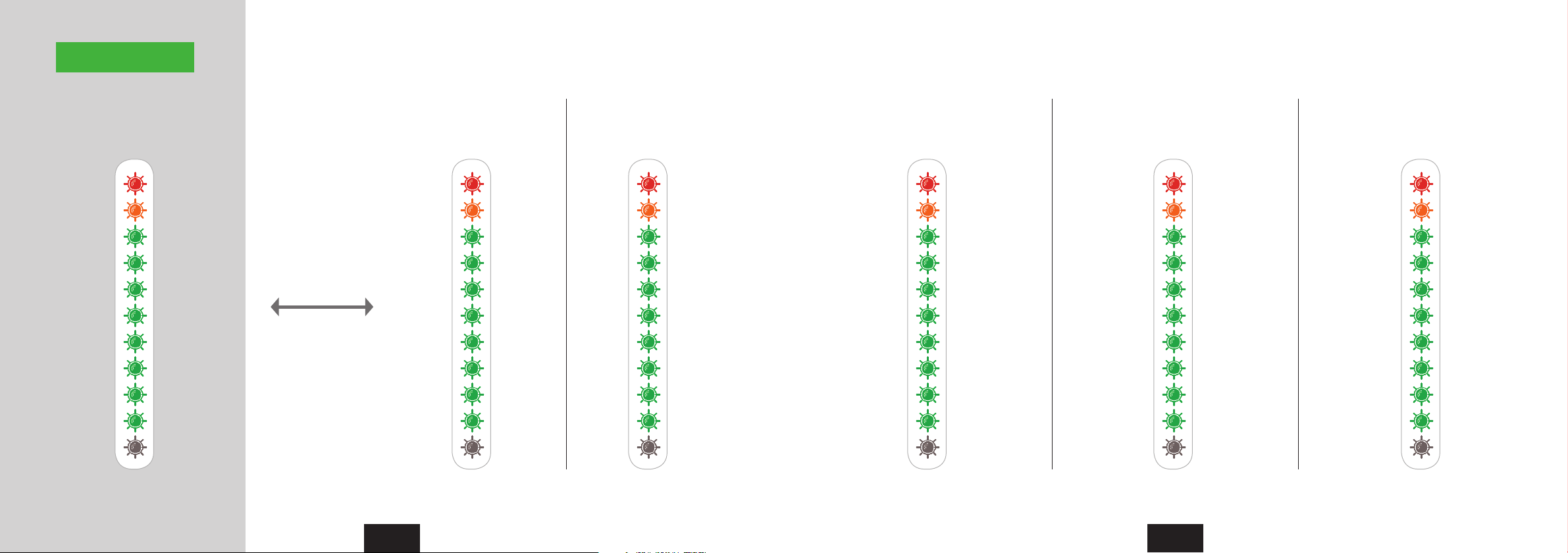
Peakmeters
Signal levels Input 1/2 Gain (Preamps)Out 1/2 (XLR) Out 3/4 (Phones) Input 2 Hi-Z Gain Input 3/4 Gain
Level in dB Gain in dBLevel in dB Level in dB Gain in dB Gain in dBLED no. StepStep Step Step Step
10 Red 2040 40 20 200 50.50 6 (Boost) 43 33
9 Orange 1837 36 18 18-3 45-1.5 2 (Boost) 42.5 29
8 Green 1634 32 16 16-6 40-3 -2 40 24
7 Green 1428 28 14 14-9 34.5-7.5 -9 34.50 20
6 Green 1224 24 12 12-12 29-11.5 -17 29 16.50
5 Green 1020 20 10 10-15 24-17.5 -29 24 13.50
4 Green 816 16 8 8-17 18.5-25 -44 18.50 10.50
3 Green 612 12 6 6-19 13.50-34.5 -63 13.50 7.50
2 Green 48 8 4 4-23 8-47 Mute 8 4.50
1 Green 22 2 2 2-27 2.5-121.5 Mute 2.50 1.50
48V
In level mode the
Nanoface shows the level
of output 1/2, input 1/2
or 3/4.
If the encoder is turned
the peakmeters switch
from the level mode to
gain mode.
Level mode
Gain mode
The view switches back
automatically after 1
second.
If Phones output (1/2 and
3/4) is selected,
the meters always show
the chosen gain.
48V48V 48V 48V 48V
2 Quick info Quick info 2
10 11
Page 7
3
Getting started
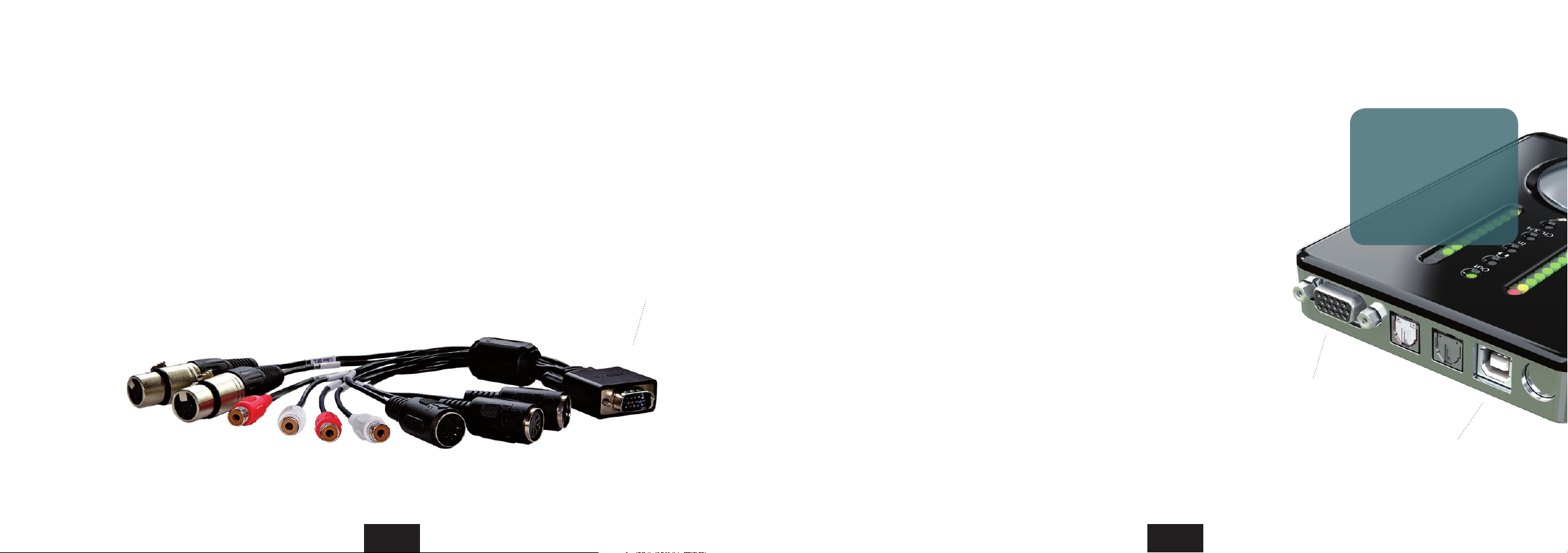
1. Connect the breakout cable 2. Connect the Nanoface to the computer
Mount the included breakout cable with the XLR and RCA connectors to the 15-pin
port on the rear of the Nanoface.
Optional extension cables for the breakout cable are available from ALVA in lengths of 1
m (3.3 ft.) and 3 m (9.8 ft.). Please visit the ALVa website for more details.
If you want to listen to music from the Nanoface after the installation process, keep a
double RCA cable ready for the connection of the breakout cable to your speakers or HiFi
preamp.
15-pin breakout cable connector
It’s possible to connect the Nanoface to every Windows or Mac
computer with a standard USB 2.0 port:
a) Connect the included USB cable to the USB 2.0 port on the back of
the Nanoface.
b) The included USB cable provides two connectors. Connect the main
connector to a free USB 2.0 port.
Tip: On every computer system we’ve tested, the Nanoface is sufficiently
powered by the main connector of the included USB cable. This means: all
3rd party USB 2.0 cables will work with the Nanoface!
Tip: In most setups a powered USB hub will also work. Keep in mind every
device on the hub will consume power from it, so it might help to connect
only the Nanoface to this hub.
The Nanoface is
completely powered by
the USB connection.
All features are available
connecting the Nanoface
with a simple USB cable to
the host computer.
15-pin breakout cable
port
12 13
USB connector
Page 8
Driver installation
Windows 32 bit and 64 bit
Always check the ALVA
website for the latest drivers:
www.alva-audio.com
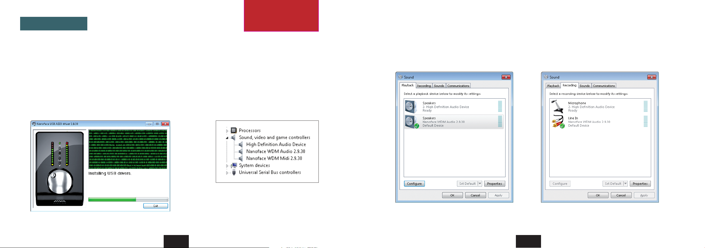
2. Windows audio setup
Set the Nanoface as default audio device for playback and recording.
1. Driver installation
1. Connect the Nanoface to your computer with the included USB cable.
2. Open the Windows driver folder on the included CD and select 32 bit or 64 bit - depending on your Windows version. Double click the
file Setup.exe.
3. Choose a language for the installation process.
4. Select “Install the driver”. The installation starts and installs the Nanoface ASIO driver for professional audio programs, like Steinberg
Cubase or Magix Samplitude, and the Windows WDM driver for the system sounds and standard audio programs (Windows Media Player,
iTunes, Winamp).
5. After the successful installation a reboot of the system is necessary.
After the successful installation the
Windows device manager shows the
Nanoface WDM Audio and MIDI devices.
Driver installation dialog
Tip . Windows 7 provides speaker sets for stereo and surround. The stereo setup assigns channels 1/2 (output RCA connectors on the breakout
cable) to the speakers. The 5.1 surround setup assigns the following channels to the speakers: Channel 1 (Front Left), Channel 2 (Front Right),
Channel 3 (Sub), Channel 4 (Center), Channel 5 (Rear Left), Channel 6 (Rear R).
Default playback device - Stereo speakers (Line outputs 1/2). Default recording device (Line inputs 1/2).
14 15
Getting started - driver installation 33 Getting started - driver installation
Page 9
Driver installation
Mac OS X
Always check the ALVA
website for the latest drivers:
www.alva-audio.com
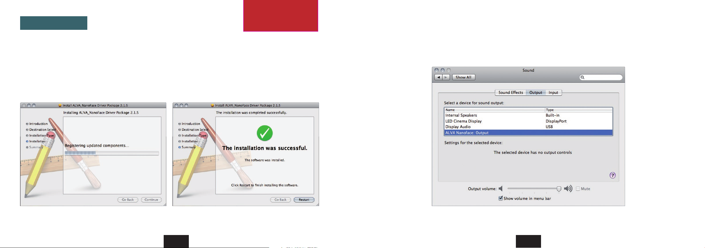
2. Mac OS X sound setup
Select ALVA Nanoface: Output in the sound setup of OS X.
1. Driver installation
1. Connect the Nanoface to your computer with the included USB cable.
2. Open the Mac OS X driver folder on the included CD and double click the .dmg file. It contains the driver installation file.
3. Double click the .mpkg file. Follow the instructions. After the selection of the installation drive - the hard disc with the operating system
- enter your administrator password to allow the installation program changes on your operating system.
4. The setup installs the Nanoface Mac OS X driver. After the successful installation a reboot of the system is necessary.
Audio programs, like iTunes, web browsers or the system sounds, use the Nanoface out channels 1/2 (output RCA connectors on the breakout
cable) for the default playback. To listen to this signal parallel on headphones, switch the phones out to channel 1/2 (see chapter Encoder
operations).
Driver installation dialog. After the successful installation click the Restart button.
16 17
Select the Nanoface for output and/or input in the system preferences of Mac OS X.
Getting started - driver installation 33 Getting started - driver installation
Page 10
4
Using the Nanoface
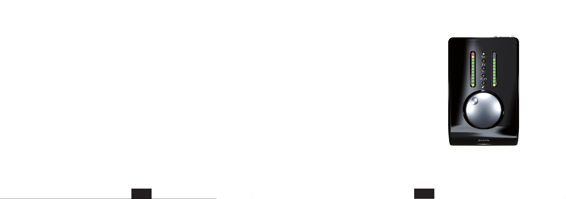
The usability concept of the Nanoface:
The analog gains for the four inputs, all output levels and special features, like phantom power and hardware monitoring will
be controlled with the big silver rotary encoder directly on the Nanoface.
All mixing, channel routing and digital levels will be controlled by your individual audio software.
Example 1: Simple audio playback:
The audio application (Windows Media Player, iTunes or a video program) plays the sound to the Nanoface, which is the default audio
output in the sound setup of Windows or Mac OS X. The sound plays on analog output 1/2.
The big encoder controls the speakers volume of output 1/2. The encoder can also duplicate the signal from output 1/2 to the
headphones output and controls the volume separately from the speakers level connected to output 1/2.
Example 2. Multitrack audio software recording and playback:
You assign the stereo monitor mix in the software to the main outputs of the Nanoface (analog output 1/2) and a seperate headphone
mix to analog output 3/4. A 3rd mix or a loop to an external effect unit can be assigned to the digital SPDIF output.
The analog preamp gain for the recording of one microphone, one electric guitar and a keyboard is controlled with the big encoder.
The monitor gain of the main speakers and the headphones is also controlled with the big encoder.
Encoder
What can be controlled:
• Output 1/2: gain
• Output 3/4 (Phones): gain
• Route output 1/2 to Phones output
• Output 1/2 on Phones output: gain
• Input 1/2: gain (mic/instr. preamps)
• Input 3/4: gain
• 48V for inputs 1 and/or 2
• Switch input 2 to Hi-Z input
• Hardware monitoring for inputs 1/2
• Reset to default values
For a more detailed step-by-step description please read the following pages.
18 19
Page 11
Encoder operations
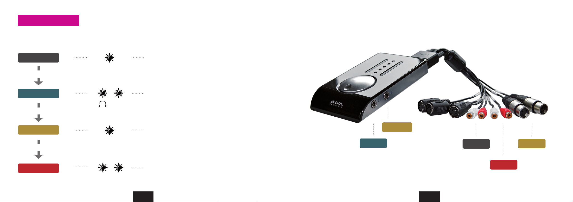
Press the encoder to switch between the input/output modes. Turn encoder to the right to increase and turn to the left to decrease the gain.
Gain control for inputs and outputs
Mode LEDs on
Analog inputs and outputs on the Nanoface
Output 1/2
The encoder controls the analog outputs 1/2 (RCA
connectors) on the breakout cable.
Out
Press Encoder
Output 3/4
The encoder controls the Phones/Line output 3/4 (1/4”
connector on right side).
3/4
Press Encoder
Input 1/2
In
Press Encoder
Input 3/4
In
4 Using the Nanoface Using the Nanoface 4
3/4
20 21
The encoder controls the preamps before the analog inputs
1/2 (XLR connectors) on the breakout cable.
Gain on channel 1: press/hold encoder and turn it one step
to the left. Switch back to 1+2: press/hold turn right.
Gain on channel 2: press/hold encoder and turn it one step
to the right. Switch back to 1+2: press/hold turn left.
The encoder controls the analog inputs 3/4 (RCA
connectors) on the breakout cable.
Output 3/4
Input 2 (Hi-Z)
Output 1/2
Input 1/2
Input 3/4
Page 12
Encoder operations Encoder operations
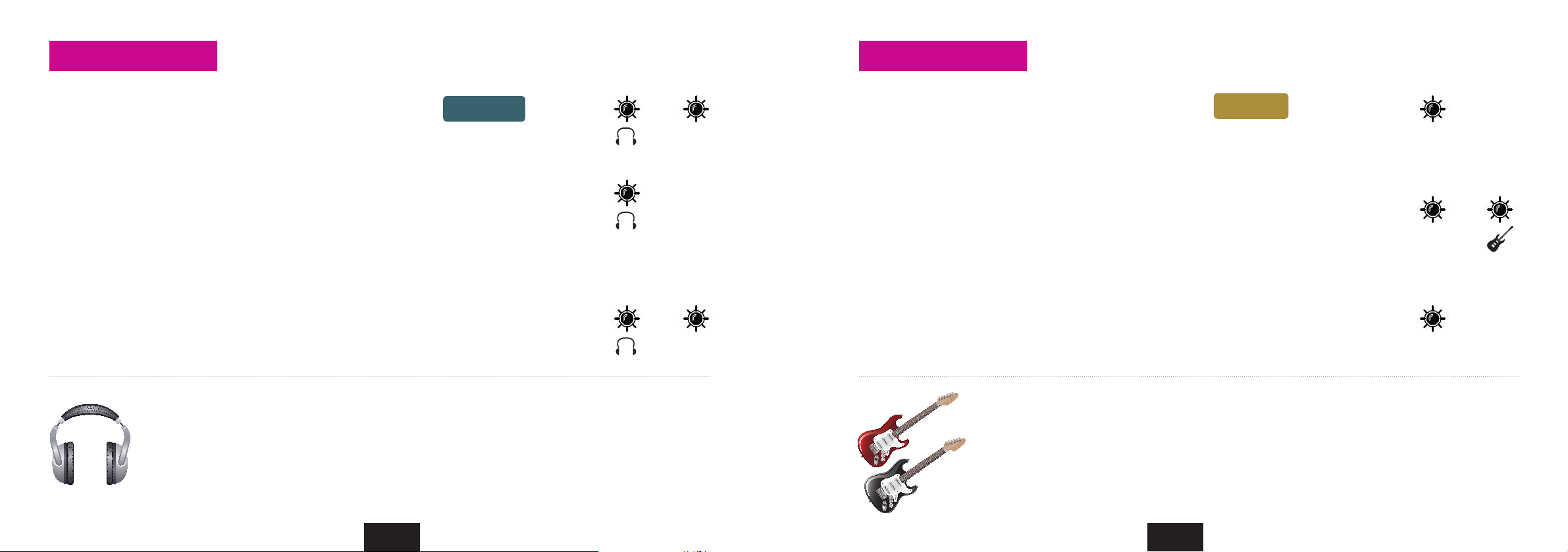
Duplicate the signal from output 1/2 on the phones output
Switch analog input 2 to the Hi-Z instrument input (“guitar input”)
1. Switch to headphones output mode.
Press the encoder until the headphones LED shines.
If LED 3/4 is on, go to step 2, if not ... the signal 1/2 is
already duplicated on the phones output.
2. Press and hold the encoder. Turn it to the left.
LED 3/4 turns off. The phones output on right side of the
Nanoface plays now the signal of output 1/2.
The encoder controls now the volume of signal 1/2 separately from
the chosen volume of output 1/2 on the breakout cable (speakers).
This is a very useful feature for a dierent headphones mix.
3. Switch the headphones back to output 3/4: Press and hold the encoder. Turn it to the right. 3. Switch back to the XLR line-input on the breakout cable: Double click the encoder.
Output 3/4
3/4
3/4
Why do I need this? If you are on the road or at home and want to listen to music played by software like Windows
Media Player, iTunes or Winamp on the headphones you need this feature.
Most audio programs can only play a signal on the default output of an audio hardware. In case of the Nanoface it’s
the analog output 1/2 on the breakout cable. The headphones output does not play this signal.
Why? In the default mode the phones output is assigned to output 3/4 of the Nanoface. This is shown by LED 3/4.
This would mean you need speakers when you just want to listen to some mp3 songs.
Solution: Just send the signal from output 1/2 to the headphones output.
1. Switch to input 1/2 mode.
Press the encoder until the input LED (“In”) shines.
If LED 3/4 also shines, press the encoder until only the
“In” LED is on (3 times).
2. Double click the encoder.
The guitar LED shines.
Analog input 2 gets it’s signal now from the Hi-Z instrument input on the right side.
The input on the breakout will not pick up any signal until the Hi-Z input is
switched o. The encoder - switched to input 2 (press/hold + turn right) adjusts now the analog preamp gain of the Hi-Z input and makes the guitar
signal louder.
The guitar LED turns off.
Why do I need this? Plugging an electric guitar or another high-impedance source in a line-level input results in
a loss of high frequencies and the sound gets dull. So it’s not a good idea to use an electric guitar or bass on the
XLR or RCA inputs of the breakout cable.
Usually a DI-box (= direct input) is used to change the high impedance of the guitar output to the low impedance
of the line level input. The Nanoface provides a special high-impedance instrument input, which can be used
alternatively to the analog input 2 on the breakout cable. If the input 2 is switched to the Hi-Z input it’s possible
to use an electric guitar or bass directly with the Nanoface.
Input 1/2
In
In
In
4 Using the Nanoface Using the Nanoface 4
22 23
Page 13
Encoder operations Encoder operations
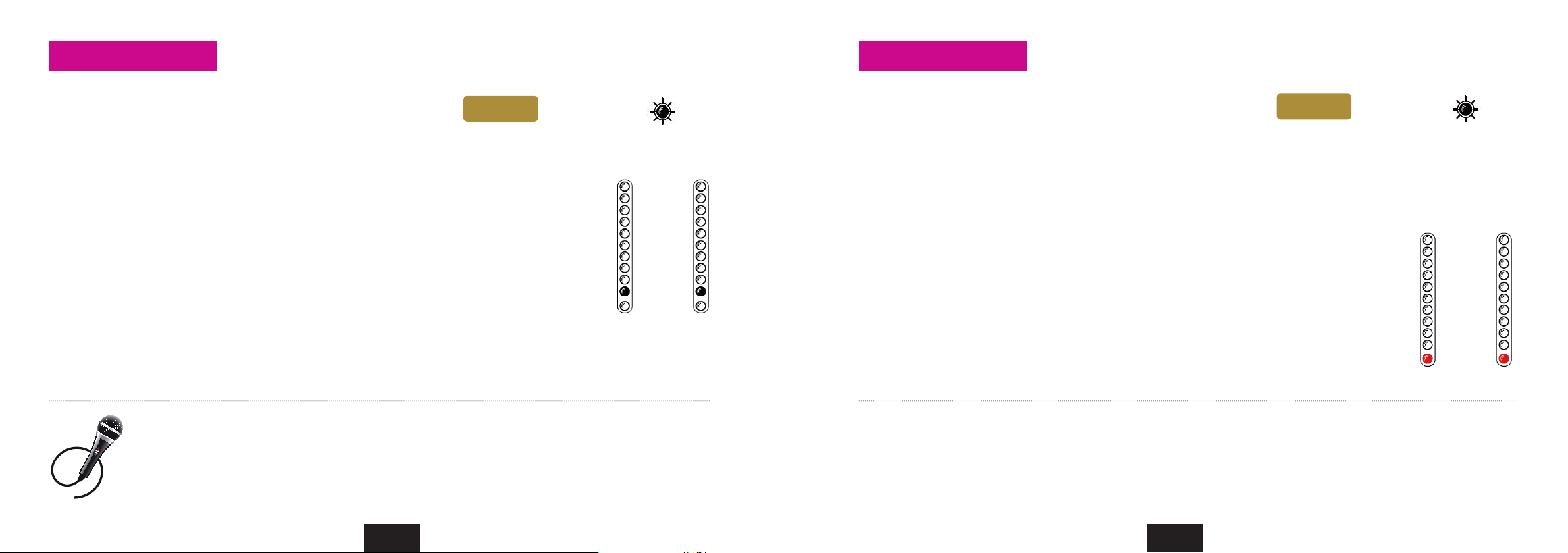
Set the preamp gain for the analog inputs 1/2 (microphones)
Turn phantom power (48V) on/o
1. Switch to input 1/2 mode.
Press the encoder until the input LED (“In”) shines.
If LED 3/4 also shines, press the encoder 3 times until only the “In” LED is on.
The encoder controls now the gain for both XLR inputs on the breakout cable.
2. Press and hold the encoder. Turn it to the left for channel 1 or turn it to the right for channel 2.
After a 1-click turn, the 1st LED of the left or right channel blinks one time to show, which channel is
selected. To switch back to gain control of channel 1+2 together, press and hold the encoder and turn
it to the right from channel 1 and to the left from channel 2.
3. Turn the encoder gradually to the right to raise the gain for the selected input(s). 3. Press the encoder for 3 seconds.
Make sure the input signal is not clipping (red top LEDs turn on).
For an exact control of the available headroom to the clipping border please use the level meter
readouts in your audio software.
Why do I need this? Microphone signals are low level signals and need to be amplified. The two Nanoface preamps
on inputs 1 and 2 provide a gain amplification of 50.5 dB. More than enough for most microphones.
Tip: To bypass the preamps of the Nanoface turn the encoder for one or both channels all the way down.
Tip: To find the best gain, play or sing the loudest reference tone in your performance and raise the gain until it clips.
Now lower it to a safe value.
Input 1/2
1
In
1st LED
blinks 1x
Input
2
1. Switch to input 1/2 mode
Press the encoder until the input LED (“In”) shines.
If LED 3/4 also shines, press the encoder 3 times until only the “In” LED is on. The
encoder controls now the gain for both XLR inputs on the breakout cable.
2. Press and hold the encoder. Turn it to the left for channel 1 or turn it to the right for channel 2.
After a 1-click turn, the 1st LED of the left or right channel blinks one time to show, which channel is
selected. To switch back to the control of channel 1+2 together, press and hold the encoder and turn
it to the right from channel 1 and to the left from channel 2.
The 1st red LED of the left chain (= input 1) turns on. If channel 2 is selected, the 1st LED in the right
chain turns on.
To avoid the accidently activation of the phantom power, it’s not possible to activate/deactivate
the phantom power at the same time for both channels. It’s only possible by a previous selection of
input channel 1or 2. If you not press the encoder long enough, the Nanoface changes to input 3/4.
Turn the phantom power o: Select channel 1 or 2 and press the encoder for 3 seconds.
Why do I need this? Condenser micprophones are built with internal active electronic elements. To operate these mics the so-called phantom
power is necessary. It’s called „phantom“ because the low power is invisible to dynamic microphones. Condenser mics will not work if they
don’t get the necessary power of usually 48V over a balanced mic cable, in most cases a XLR cable. In this case the supply voltage is referenced
to the ground pin of the connector, pin 1 of the XLR connector.
Tip: Some semi-professional condenser mics provide internal battery powering and don’t need the 48V power from the Nanoface. If you ask
yourself if your microphone needs phantom power or not, please have a look on the documentation or consult the manufacturer.
Input 1/2
In
Input
1
2
4 Using the Nanoface Using the Nanoface 4
24 25
Page 14
Encoder operations
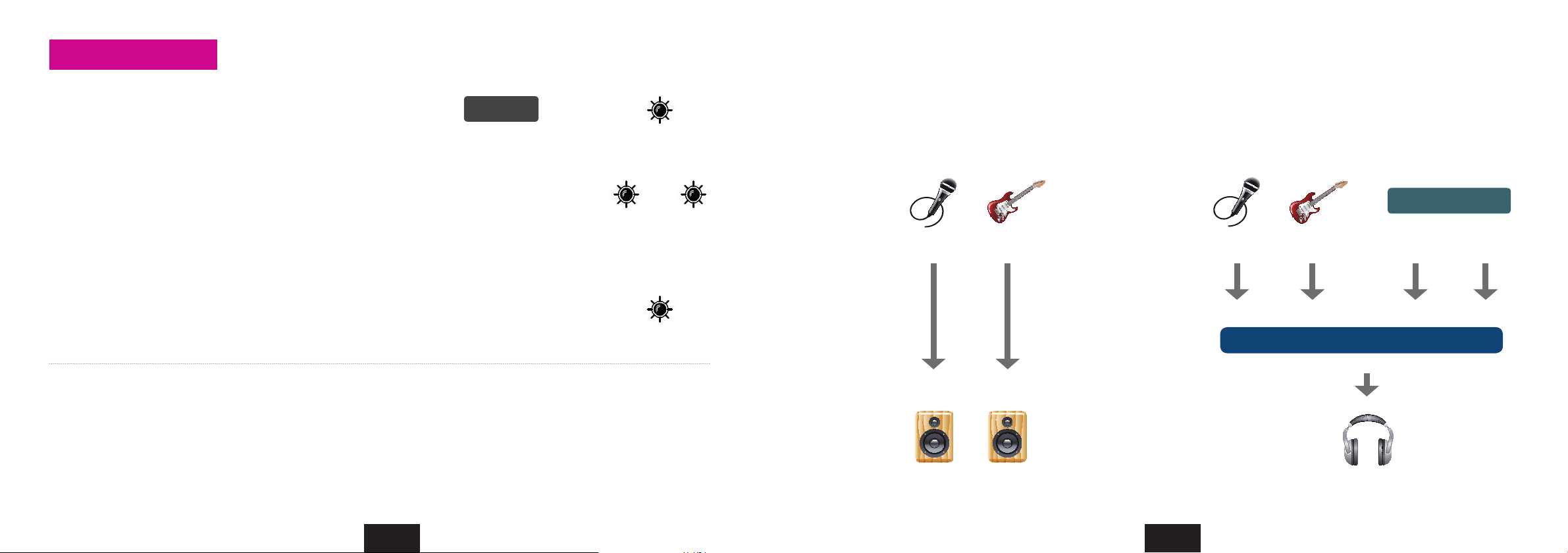
Switch hardware monitoring for analog input 1/2 on/o
Nanoface Hardware Monitoring
1. Switch to Output 1/2 mode.
Press the encoder until only the “Out” LED shines.
Output 1/2
Out
2. Switch hardware monitoring on: Double click the encoder.
The “In” LED starts blinking.
- The signal of the analog inputs 1/2 is directly routed in hardware to the analog output 1/2.
- Input 1/2 + software output 1/2 (signal from the from the computer) will be mixed to a mono
signal on phones output 1/2 (switch from phones 3/4 to 1/2).
See next page.
Switch hardware monitoring o: Choose Output 1/2 and double click the encoder.
Out In
(blinks)
Out
Why do I need this? Monitoring through modern audio software has big advantages: the signal can be mixed with other tracks, routed to
different outputs and it can be processed with plug-in effects (e. g. reverb on vocals, virtual guitar racks). Unfortunately this way of working
always introduces latency. The latency depends on the combination of the host computer, the audio software and the used plug-ins and the
driver of the audio interface. If the latency is too large, it’s nearly impossible for a live performer to play or sing with software monitoring. For
example: A drummer will have big problems in his performance when he listens to a delayed headphone signal.
To avoid any software latency the Nanoface provides with hardware monitoring a technique of routing the input signal directly to the output
of the audio card, without passing it through the software. It works like a direct cable connection from the inputs to the outputs.
Analog inputs 1/2 (XLR or Hi-Z input)
is routed directly to the RCA outputs 1/2
Analog inputs 1/2 + software output 1/2
are mixed to a mono signal on phones output 1/2
Audio software
Mix to a mono signal
4 Using the Nanoface Using the Nanoface 4
26 27
Page 15
5
Connecting equipment
Connectivity
• Audio: 6 inputs + 6 outputs
• MIDI: 1 x input + 2 x output
• 4 x analog I/O (channels 1-4)
• Digital optical SPDIF I/O (channels 5-6)
• 2 x Mic preamps including phantom power
(analog inputs 1/2)
• 1 x Hi-Z instrument input
(alternatively usable instead of analog input 2)
28
The Nanoface provides 6 audio I/Os – more than enough
for a small home studio, a DJ- or surround setup.
A MIDI input and two MIDI outputs allow to connect a
master keyboard and two external synthesizers or samplers.
Four analog inputs – two of them equipped with highquality mic preamps - allow the simultaneously recording
of different sources at the same time, like a microphone, an
electric guitar and a synthesizer.
Four analog outputs provide a flexible setup for monitoring
two stereo signals at the same time, e. g. with main speakers
and headphones. The signal from output 1/2 can be routed
to output 3/4 and individually adjusted.
The digital I/O works in standard SPDIF format. This makes
the Nanoface the perfect partner for a digital signal from a
CD player or an effect unit.
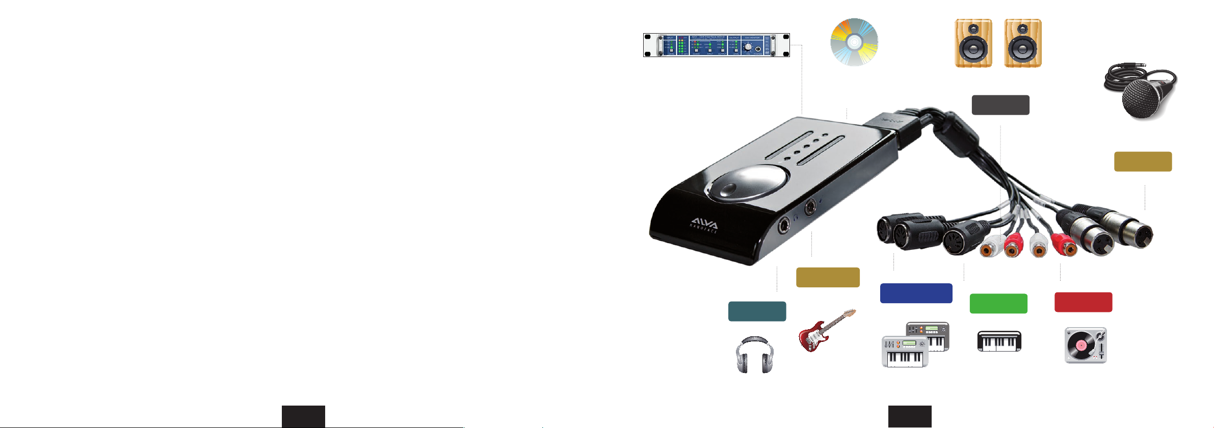
Nanoface connection example 4
DA converter
(on the digital optical output)
Output 3/4
Phones
(or 2nd speaker pair)
CD/DVD player
(on the digital input)
Input 2 (Hi-Z)
Electric guitar
MIDI Output 1/2
2 x Synthesizer (MIDI)
29
Main speakers
Output 1/2
MIDI Input
Keyboard (MIDI)
Microphone
Input 1
Input 3/4
Turntable or tape recorder
Page 16
Connecting the outputs
Speakers
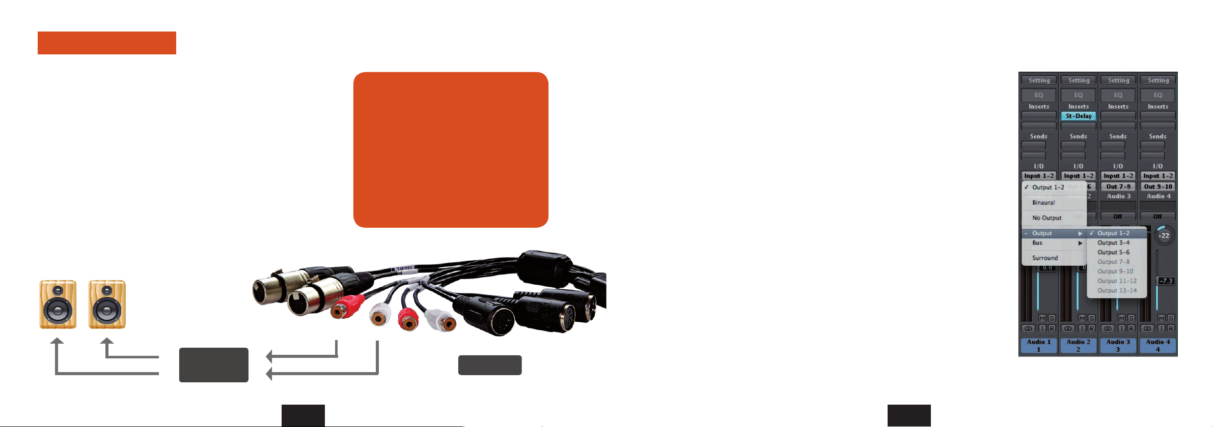
1. Cable Connection
Connect the speakers to the output RCA connectors on the breakout cable.
Output 1 goes to the left speaker and output 2 to the right.
The outputs are labled Out 1 / Out 2 and use unbalanced connections to match
the connectors of usual home audio equipment. For the connection use a
paired RCA cable.
Keep in mind, that for a satisfied level, a pair of active speakers or a HiFi preamp
might be necessary.
Attention: Always turn down the level before you connect active powered
speakers to the Nanoface. Turn off your active speakers or your preamp before
you start the computer or connect the Nanoface to avoid a potentially damage
of your equipment or hearing loss.
Speakers (passive)
HiFi Preamp
The Nanoface provides 4 analog outputs
in two stereo pairs:
• Output 1/2 on the breakout cable
(output RCA connectors).
• Output 3/4 as 1/4“ TRS connector on the
right side of the Nanoface (headphones
symbol).
Both signals can be used as an output for
different signals (e. g. main mix + headphones
mix) from the multitrack software.
Output 1/2
2. Playback with audio programs
Choose the Nanoface in the Windows or Mac OS X audio setup as the default sound
device.
Audio programs, like Windows Media Player, iTunes, Winamp or VLC will now automatically
use the Nanoface output 1/2 and play their signals to the speakers.
Tip. Some audio or video programs, like the video player VLC, provide a selection from
a list of all available audio devices. In this case it’s possible, to choose the Nanoface as
playback device even when it’s not the default sound device in the operating system.
Tip. It is recommended, to switch all system sounds off in Windows to avoid problems
with other audio programs.
3. Multichannel audio programs
The Nanoface is a multitrack audio interface. The dierent outputs are available via
the driver to any audio software and the operating system, which supports multiple
audio outputs.
For the playback on the speakers with a professional multichannel audio software, like
Steinberg Cubase, Apple Logic, AVID Pro Tools or Reaper, just to name a few, two steps
are necessary:
• Choose the Nanoface in the audio setup of this program (e. g. ASIO device setup
in Cubase or Wavelab).
• Select Output 1/2 in the track (stereo audio track, submix bus or master out),
which should be play its’ signal on the speakers.
Output channel selection in Apple Logic
5 Connecting equipment to the outputs
30
31
Connecting equipment 5
Page 17
Connecting the outputs
Headphones (or 2nd pair of speakers)
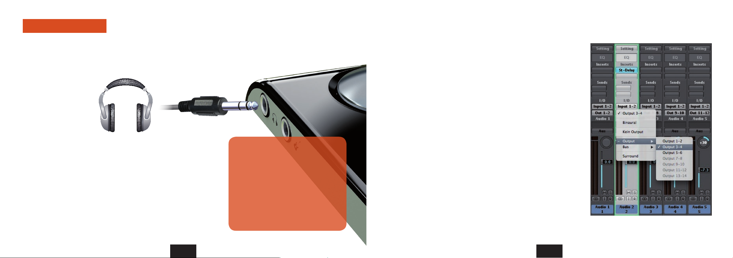
1. Cable Connection
Connect the headphones to the phones output on the right side of the
Nanoface. A 1/4 inch TRS connector or an adapter from Mini-TRS-plug to 1/4
inch TRS is necessary.
With a Y-TRS-adapter the
phones output can be
used as 2nd line output
for a 2nd pair of speakers.
Output 3/4 provides 100
Ohm and can drive any type
of low or high impedance
headphones.
Attention: Always turn down the level before you connect your headphones
to the Nanoface. Don’t wear headphones during the start of the computer or
the connection of the Nanoface to USB to avoid potential hearing loss.
1/4” TRS connector
2. Playback with audio programs
Standard Windows or Mac OS X programs cannot play on the output 3/4. If
the Nanoface is the default sound device in the audio setup, those programs
play on the output 1/2 on the breakout cable (speakers).
To listen to the signal on the headphones you have to duplicate the outout
1/2 on the phones out:
The Nanoface provides 4 analog outputs
in two stereo pairs:
• Output 1/2 on the breakout cable
(output RCA connectors).
• Output 3/4 as 1/4 inch TRS connector
on the right side of the Nanoface
(headphones symbol).
Both signals can be used as output for a
different signals (e. g. main mix + headphones
mix) from the multitrack software.
1. Switch to headphones output mode.
Press the encoder until the headphones LED and the LED Ch. 3/4 shines.
This means the phones output plays now channels 3/4.
2. Press and hold the encoder. Turn it one step to the left.
LED 3/4 turns off. The phones output plays now the signal of output 1/2.
The encoder controls the volume of signal 1/2 separately from the
chosen volume of output 1/2 on the breakout cable (speakers).
To switch back to channel 3/4 on the phones choose headphones mode
again and click/hold + turn the encoder one step to the right.
3. Multichannel audio programs
The Nanoface is a multitrack audio interface. The dierent outputs
are available via the driver to any audio software and the operating
system, which supports multiple audio outputs.
For the playback on the headphones with a professional multichannel
audio software, like Steinberg Cubase, Apple Logic, AVID Pro Tools or
Reaper, just to name a few, two steps are necessary:
• Choose the Nanoface in the audio setup of this program.
• Select Output 3/4 in the track (stereo track, submix bus or master
out), which should be play his signal on the phones.
Output channel selection in Apple Logic
5 Connecting equipment to the outputs
32
33
Connecting equipment 5
Page 18
Connecting the outputs
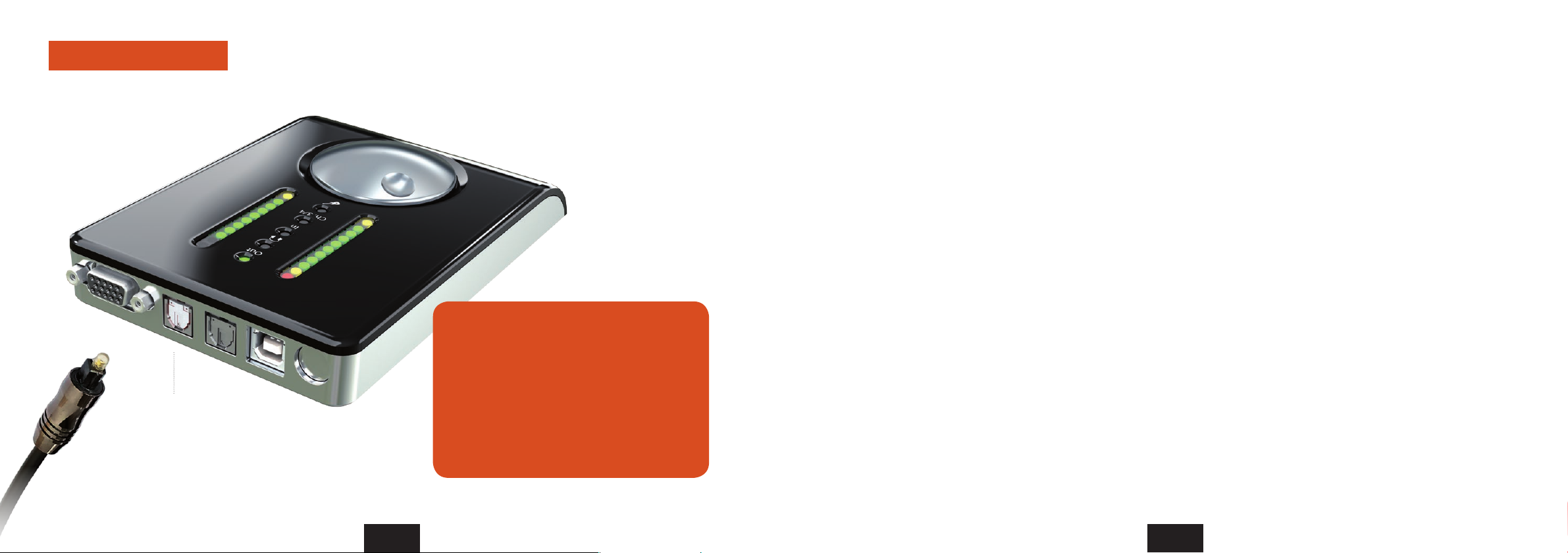
Digital S/PDIF output
(red light)
Digital equipment to the optical S/PDIF output
The Nanoface provides a digital SPDIF I/O in
the optical TOSLINK format (channel 5/6).
The S/PDIF I/O supports stereo format for
uncompressed PCM signals (WAV, AIF, mp3 ...). It
is used by the usual playback in a DAW, Windows
Media Player, iTunes and other audio programs.
The S/PDIF I/O supports also compressed surround
formats, like AC3 on Microsoft Windows.
1. Cable Connection
To send a digital signal from the Nanoface to another device, connect a standard
optical lightpipe cable from the optical output on the back of the Nanoface to digital
input of your external equipment. This could be an external DA converter, a HiFi
system, another audio interface or an external DA converter.
2. Playback with audio programs
Standard Windows or Mac OS X programs usually cannot play on the output 5/6. If
the Nanoface is the default sound device in the audio setup, those programs play
on the output 1/2 on the breakout cable (speakers). Some audio or video programs
provide an option to play on an available S/PDIF output.
Keep in mind, it’s not possible, to listen or route the S/PDIF output to the speakers or
the headphones. It’s a digital format and needs a previous digital to analog conversion
before it can be heard.
3. Multichannel audio programs
The Nanoface is a multitrack audio interface. The dierent outputs are available via
the driver to any audio software and the operating system, which supports multiple
audio outputs.
For the playback on the headphones with a professional multichannel audio software,
like Steinberg Cubase, Apple Logic, AVID Pro Tools or Reaper, just to name a few, two
steps are necessary:
• Choose the Nanoface in the audio setup of this program.
• Select Output 5/6 in the track (stereo audio track, submix bus or master out),
which should be play its signal on the digital out.
Digital Clock. Digitally connected devices
need a so-called Word Clock to run in sync.
One device has to be the clock master - which
sets the clock for all connected devices - and
the other has to be the clock slave.
The Nanoface is the clock master and uses
the sample rate from the audio program on
the host. Other devices - like a DA converter
- run as clock slave to the Nanoface and use
the provided sample rate (e. g. 44.1 or 96 kHz).
If the Nanoface is connected to another digital
device through its optical input, it runs as a
slave and uses the clock of this master device.
5 Connecting equipment to the outputs
34
35
Page 19
Connecting the outputs Connecting the inputs
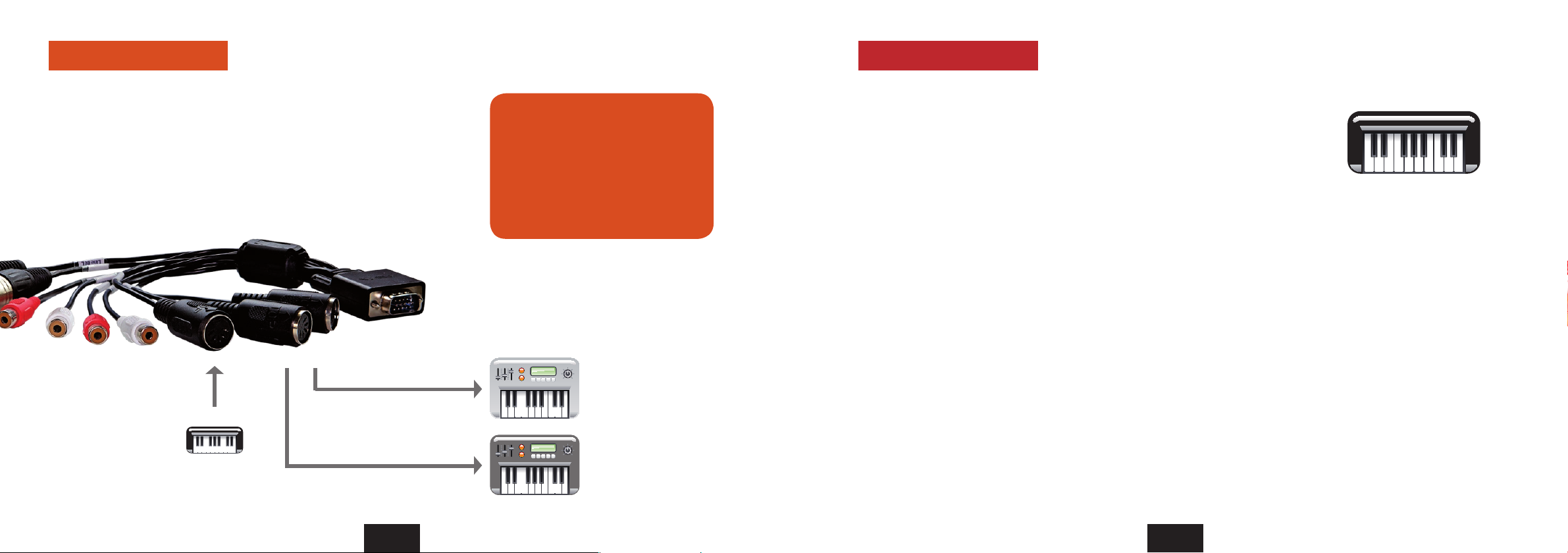
MIDI sound equipment MIDI keyboard
1. Cable Conncetion
Connect external MIDI equipment via standard 5-pin MIDI cables to the MIDI
outputs 1 and 2.
2. MIDI programs
Both outputs are available for MIDI playback in any MIDI program or sequencer.
MIDI output 1
MIDI input
MIDI output 2
MIDI Keyboard
The Nanoface provides a MIDI input
and two MIDI outputs via standard
DIN-jacks on the breakout cable.
After the driver installation the MIDI
ports are available for any MIDI software.
As standard MIDI ports, each output
adds 16 MIDI channels to the setup.
Sound modules,
samplers, workstations,
electric pianos, synthesizer
or other MIDI equipment.
1. Cable Connection
Connect an external MIDI master keyboard via a standard 5-pin MIDI cable to
the MIDI input.
The MIDI data will be transmitted via the USB cable to the host computer and
then to the MIDI software. A direct MIDI through from the input to a MIDI output
of the Nanoface without MIDI software on the host computer is not possible.
2. Record the MIDI data in a MIDI program
The MIDI input is available in any MIDI program or sequencer. Received MIDI
events can be recorded after the selection of the Nanoface MIDI input as
source for a MIDI track.
What is MIDI?
MIDI signals include trigger instructions for
a sound device, but no sound. It needs a
MIDI sound module, a virtual instrument or
a sampler to create an audible “sound”. In
contrary to audio files, like WAV or AIF or even
MP3, MIDI files are very small.
Example: A piano solo played on the master
keyboard creates trigger information: note,
octave, note on and note off, dynamic and
others.
This information will be interpreted by a MIDI
sound module, a sampler or synthesizer, which
generate the final piano sound.
5 Connecting equipment to the outputs
36
37
Connecting equipment to the inputs 5
Page 20
Connecting the inputs
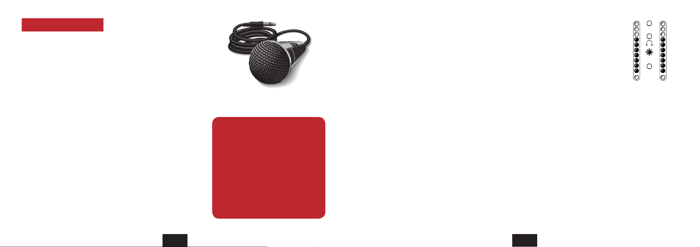
Dynamic microphones
1. If phantom power is activated, turn it o.
The 1st red LED in the channel(s) to which the microphone will be connected
has to be tunred o (input 1 = left LED; input 2 = right LED).
Attention! Activated phantom power can damage other equipment (e. g. ribbon
mics). Phantom power should always be turned of if it’s not needed for a connected
condenser microphone. In contrary to condenser microphones (see next page),
dynamic microphones, like the Shure SM57 and SM58, don’t use internal electronic
components which needs to be fed by external phantom power. Before you connect
such a mic to analog input 1 or 2, make sure the phantom power is not active. The first
red LED in the channel to which the microphone is connected, has to be off.
Turn phantom power o: Switch to input mode, select channel 1 or 2 and
press the encoder for 3 seconds. The 1st red LED in this channel stops shining.
2. Cable Connection
Connect one or two dynamic microphones to the XLR inputs 1 and/or 2. For
the connection of condenser mics please read the next page.
Attention! Keep in mind, microphones in the vicinity of speakers can cause
loud and dangerous sounds. They can not only damage your hearing but also
your equipment. Always try to keep a safe distance between microphones and
speakers and lower the volume of the Nanoface preamp gain and the output
level before the connection process.
The Nanoface provides 2 XLR microphone
inputs with optional phantom power (48V)
on the breakout cable.
Microphone signals are low level signals and
need a preamplifier to boost them to a usable
line-level signal. The Nanoface provides two
mic preamps on input 1 and 2 for any kind of
microphone type and level. Both inputs are
equipped with preamps of up to 50.5 dB gain.
If input 2 is switched to the instrument input on
the right side of the Nanoface (guitar symbol),
it’s possible to connect only one microphone
to input 1. Input 2 on the breakout cable is off.
3. Select the channel for the preamp gain
Step 1) Switch to input 1/2 mode.
Press the encoder until the input LED (“In”) shines. If LED 3/4 also shines, press the encoder 3 times until only
the “In” LED is on.
Test the mic: you should see activity on the meters of the LED chain. Channel 1: left LEDs; Channel 2: right LEDs.
The encoder now controls the gain for both XLR inputs on the breakout cable. If you want to set a different
gain for every mic continue with step 2.
Step 2) Press and hold the encoder. Turn it to the left for channel 1 or turn it to the right for channel 2.
After a 1-click turn, the 1st green LED of the left or right channel blinks one time to show, which channel is
selected. To switch back to the gain control of channel 1+2 together, press and hold the encoder and turn it to
the right from channel 1 and to the left from channel 2.
4. Set the preamp gain
Turn the encoder gradually to the right to raise the gain for the selected input(s).
Make sure the input signal is not clipping (red top LEDs turn on). For an exact control of the available headroom
to the clipping border please use the level meter readouts in your audio software.
4. Record the signal from the microphone on the computer
To record the microphone signal in your audio software, choose the Nanoface as audio interface, create
a mono track and choose channel 1 as input. For a mic on input 2 create another mono track and choose
channel 2 as input.
Out
In
Ch. 3/4
Input 1 Input 2
5 Connecting equipment to the inputs
38
39
Connecting equipment to the inputs 5
Page 21
Connecting the inputs
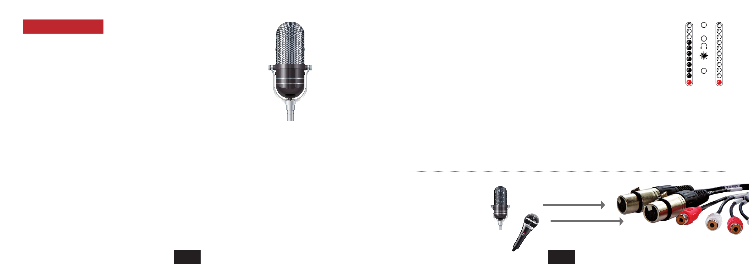
Condenser microphones
1. Cable Connection
Connect one or two condenser microphones to the XLR inputs 1 and/or 2.
Attention! Keep in mind, microphones in the vicinity of speakers can cause
loud and dangerous tones. They can not only damage your hearing but also
your equipment. Always try to keep a safe distance between microphones and
speakers and lower the volume of the Nanoface preamp gain and the output
level before the connection process.
2. Select a channel for the preamp gain
Step 1) Switch to input 1/2 mode.
Press the encoder until the input LED (“In”) shines. If LED 3/4 also shines, press
the encoder 3 times until only the “In” LED is on.
Test the mic on input 1 by speaking or singing: you should see activity on the
meters of the left LED chain. Channel 2: activity on the right LED chain.
The encoder now controls the gain for both XLR inputs on the breakout cable. If
you want to set a different gain for every mic continue with step 2.
Step 2) Press and hold the encoder. Turn it to the left for channel 1 or turn it
to the right for channel 2.
After a 1-click turn, the 1st green LED of the left or right channel blinks one
time to show, which channel is selected. To switch back to the gain control of
channel 1+2 together, press and hold the encoder and turn it to the right from
channel 1 and to the left from channel 2.
Condenser mics vs. dynamic mics
Condenser micprophones are built with internal
active electronic elements. To operate these mics
the so-called phantom power is necessary.
The phantom power transmits DC electric power
through typical XLR microphone cables.
Some semi-professional condenser mics provide
internal battery powering and don’t need the 48V
external power from the Nanoface.
If you are not sure if your microphone needs
phantom power or not, please have a look on the
documentation or consult the manufacturer.
3. Turn phantom power on
Press the encoder for 3 seconds.
The 1st red LED of the left chain (= input 1) or turns on. If channel 2 is selected, the 1st LED in the right chain turns on.
To avoid the accidental activation of the phantom power, it’s not possible to activate/deactivate the phantom power
at the same time for both channels. It’s only possible by a previous selection of input channel 1or 2. If you don’t press
the encoder long enough, the Nanoface changes to input 3/4.
Attention! Before you connect other equipment to analog input 1 or 2, make sure the phantom power is not active.
Turn the phantom power o: Select channel 1 or 2 and press the encoder for 3 seconds.
3. Set the preamp gain
Turn the encoder gradually to the right to raise the gain for the selected input(s).
Make sure the input signal is not clipping (red top LEDs turn on). For an exact control of the available headroom to
the clipping border please use the level meter readouts in your audio software.
4. Record the signal from the microphone on the computer
To record the microphone signal in your audio software, choose the Nanoface as audio interface, create a mono
track and choose channel 1 as input. For a mic on input 2 create another mono track and choose channel 2 as
input.
Connection example
Mic 1 (Condenser - 48V on)
Mic 2 (Dynamic - 48V off )
Input 1 (XLR - Line In)
Input 2 (XLR - Line In R)
Out
In
Ch. 3/4
Input 1 Input 2
If phantom power is
enabled the 1st red
LED shines.
5 Connecting equipment to the inputs
40 41
Connecting equipment to the inputs 5
Page 22
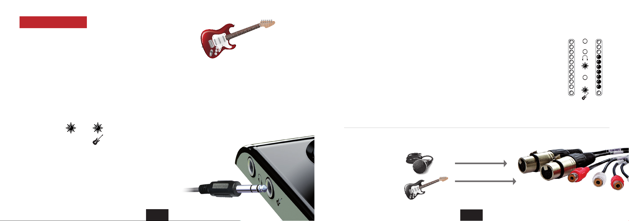
Connecting the inputs
Electric guitar or bass
1. Cable Connection
Connect the electric guitar or bass to the Hi-Z input on the right site of the
Nanoface (guitar symbol).
2. Switch to input 1/2
Press the encoder until the input LED (“In”) shines. If LED 3/4 also shines,
press the encoder 3 times until only the “In” LED is on.
3. Turn the Hi-Z input on: double click the encoder
The guitar LED turns on. Analog input 2 now get it’s signal from the Hi-Z
instrument input on the right side. The input on the breakout cable will not
pick up any signal until the Hi-Z input is turned o (double click).
In
4. Select channel 2
Press and hold the encoder. Turn it to the right to select channel 2.
After a 1-click turn, the 1st green LED of the right chain blinks one time to show
channel 2 is selected.
To switch back to the gain control of channel 1+2 together, press and hold the
encoder and turn it to the left.
Why does it need a Hi-Z instrument input?
Plugging an electric guitar or bass in a line-level
input results in a loss of high frequencies and the
sound gets dull.
Usually a DI-box (= direct input) is used to change
the high impedance of the guitar output to the
low impedance of a line level input.
With a special Hi-Z input for the direct recording
of electric instruments the Nanoface provides all
necessary inputs. Just plug the guitar in.
5. Set the preamp gain
Turn the encoder gradually to the right to raise the gain, turn it to the left to lower it.
The Nanoface provides a gain of up to 43 dB on the instrument input. The gain is adjustable in 20 steps.
Make sure the input signal is not clipping (red top LEDs turn on). For an exact control of the available
headroom to the clipping border please use the level meter readouts in your audio software.
4. Record the signal from the instrument input on the computer
To record the guitar in your audio software, choose the Nanoface as audio interface, create a mono
track and choose channel 2 as input.
Connection example
Input 1 (XLR - Line In)
Dynamic microphone
Electric bass guitar
Input 2 (Hi-Z input - right side)
Out
In
Ch. 3/4
Input 1 Input 2
5 Connecting equipment to the inputs
42 43
Connecting equipment to the inputs 5
Page 23
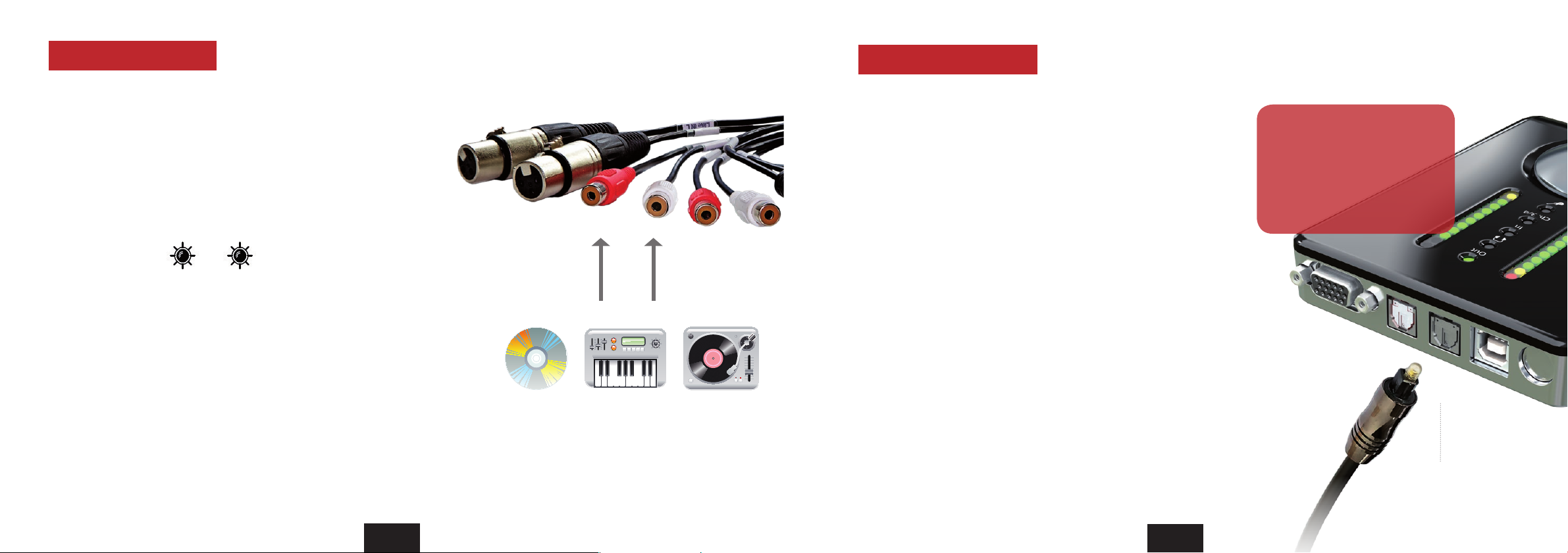
Connecting the inputs
External equipment to the line inputs 3/4
Connecting the inputs
Digital equipment to the optical S/PDIF input
1. Cable Connection
Connect any line level equipment to the RCA input connectors on the
breakout cable. This could be a tape recorder, a synthesizer output, a CD
player or a turntable (with RIAA EQ preamp).
2. Switch to input 3/4
Press the encoder until the input LED (“In”) and LED 3/4 shines.
In 3/4
3. Set the input gain
Turn the encoder gradually to the right to raise the gain, turn it to the left
to lower it.
The Nanoface provides a gain of up to 33 dB on line input 3/4. The gain is
adjustable in 20 steps.
Make sure the input signal is not clipping (red top LEDs turn on). For an exact
control of the available headroom to the clipping border please use the level
meter readouts in your audio software.
1. Cable Conncetion
To send a digital signal to the Nanoface, connect a standard optical
lightpipe cable to the optical input on the back of the Nanoface. This
could be an external AD converter, a CD player, HiFi system or another
audio interface.
2. Record the signal
To record from the digital input in your audio software, choose the
Nanoface as audio interface, create a stereo track and choose channel
5/6 as input.
To listen to this signal, route input channel 5/6 to the analog output 1/2 or
3/4 in your audio software (software monitoring).
The Nanoface provides a digital
SPDIF I/O in the optical TOSLINK
format (channel 5/6).
If a digital signal is present on the
input the Nanoface runs as clock
slave.
Digital S/PDIF input
5 Connecting equipment to the inputs
44 45
Connecting equipment to the inputs 5
Page 24

Appendix
6
1. Nanoface downloads
Driver and manual updates can be found on our website: www.alva-audio.com
2. Distributor contact
The worldwide distributor of the Nanoface:
Audio AG
Am Pfanderling 60
D-85778 Haimhausen
Germany
Tel.: +49 (0) 8133 / 918170
Fax: +49 (0) 8133 / 9166
E-Mail: [email protected]
Internet: www.audioag.com
3. Declaration of Conformity
CE . The Nanoface has been tested and found to comply with the limits of the European Council Directive on the approximation
of the laws of the member states relating to electromagnetic compatibility according to RL2004/108/EG, and European Low
Voltage Directive RL2006/95/EG.
FCC . This device complies with Part 15 of the FCC Rules. Operation is subject to the following two conditions: (1) this device may
not cause harmful interference, and (2) this device must accept any interference received, including interference that may cause
undesired operation.
Warning: Changes or modications to this unit not expressly approved by the party responsible for compliance could void the
user’s authority to operate the equipment.
NOTE: This equipment has been tested and found to comply with the limits for a Class B digital device, pursuant to Part 15 of the
FCC Rules. These limits are designed to provide reasonable protection against harmful interference in a residential installation.
This equipment generates, uses and can radiate radio frequency energy and, if not installed and used in accordance with the
instructions, may cause harmful interference to radio communications.
However, there is no guarantee that interference will not occur in a particular installation. If this equipment does cause harmful
interference to radio or television reception, which can be determined by turning the equipment o and on, the user is
encouraged to try to correct the interference by one or more of the following measures:
Reorient or relocate the receiving antenna. Increase the separation between the equipment and receiver. Connect the equipment
into an outlet on a circuit dierent from that to which the receiver is connected. Consult the dealer or an experienced radio/
TV technician for help. U.S. responsible party info: Synthax United States, 1700 NW 65th Ave ste 7, Fort Lauderdale,FL33313,
Phone:330.259.0308 ext 281
Note on Disposal . According to the guideline RL2002/96/EG - WEEE – Directive on Waste Electrical and Electronic Equipment),
valid for all european countries, the Nanoface has to be recycled at the end of its lifetime.
In case a disposal of electronic waste is not possible, the recycling can also be done by the Nanoface distributor. Send it free to
the door of Audio AG (adress on page 46). Unprepaired shipments will be rejected and returned to the costs of the sender.
5 Appendix
46 47
Page 25
 Loading...