


M-PD93X
INSTRUCTION MANUAL
06.10
M003

Dimensions from wall to center of threshold
FRONT
MODEL
4836 45 7/8” 46 3/8” 33 7/8” 34 3/8”
6036 57 7/8” 58 3/8” 33 7/8” 34 3/8”
4832 45 7/8” 46 3/8” 29 7/8” 30 3/8”
4848 45 7/8” 46 3/8” 45 7/8” 46 3/8”
6032 57 7/8” 58 3/8” 29 7/8” 30 3/8”
6048 57 7/8” 58 3/8” 45 7/8” 46 3/8”
(DIM A)
MIN MAX MIN MAX
SIDE
(DIM B)
2 PEOPLE REQUIRED

Please keep this manual and product code number for future reference and re-
placement parts ordering if necessary.
GENERAL INSTRUCTIONS
• Read this manual carefully and completely before
proceeding.
• It is recommended that you wear safety glasses at
all times during the installation.
INSTALLATION OVER CERAMIC TILES
• Silicone should be used to seal the gap where the
ceramic tiles meet the panel.
• If your shower door is to be installed over ceramic
tiles, the tiles should lay completely under the wall
jamb.
NOTICE
• Caulking: no sealant is required inside the shower.
Unless otherwise stated.
• Some models are equipped with clear sealing
gaskets.
CARE FOR YOUR SHOWER DOOR
• Never use scouring powder pads or sharp instruments on metal pieces or glass panels. An occasional wiping down with a mild soap diluted in water
is all that is needed to keep the panels and aluminum parts looking new.
• We recommend wiping the glass panels with a
squeegee after each use.
Product are subject to change without
notice.

PARTS LISTING
INSTALLATION MANUAL
HARDWARE
1
16
3
17 20
18 19
4
2221
23
8
9
10
24
25
11
12
26
ITEM PARTS QTY
1 SUPPORT BAR 1
2 SUPPORT BAR 1
3
4 SIDE PANEL 1
5 RETURN PANEL 1
6
7
8 DOOR PANEL 1
9
10 HINGES 2
11 BOTTOM DOOR GASKET 1
12
13 THRESHOLD = (FINISHED WALL OPENING) 1
14 MAGNETIC RETURN PANEL GASKET 1
15
16 - SIDE PANEL GASKET 1
ITEM HARDWARE QTY
17 SPACING BLOCKS 2
18 WALL PLUG 7
19 SCREW CAP 7
20 BACK SCREW CAP 7
21 SELF DRILLING SCREW# 8- 3/8” 6
22 SELF-DRILLING SCREW # 8- 1-1/4” 6
23 FLAT HEAD SCREW # 6 - 1” 4
24 BOTTOM GLASS CLIP 4
25
26 CLEAR SETTING BLOCK 8
27 CLEAR SETTING BLOCK 8
27
WALL JAMB (REGULAR PUNCH) 2
UNIVERSAL EXPANDER
GASKET
STRAIGHT HANDLE BAR 1
THRESHOLD = (FINISHED WALL OPENING) 1
MAGNETIC DOOR GASKET 1
PVC GASKET 4
2
5
6
7
13
14
15
2
2
4
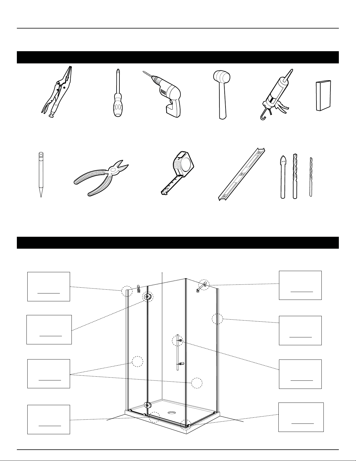
TOOLS AND MATERIAL REQUIRED
INSTALLATION MANUAL
PXL4836
LONG NOSE LOCKING PLIER (X2)
PENCIL
*
To install the shower door on ceramic tiles, use a 1/4’’ drill bit for ceramic tiles
CUTTING PLIER LEVELTAPE MEASURE
DRILL SILICONESCREWDRIVERS
INSTALLATION OF COMPONENTS
STEP 1
• Wall Jamb
see page 28
MALLET
BLOCK
*
1/4˝& 1/8˝ DRILL BITS
STEP 7
• Support bar
see page 34
STEP 4
• Door panel & hinges
see page 31
STEP 3
• Fix & return panel
see page 30
STEP 2
• Threshold
see page 29
STEP 5
• Expander
see page 32
STEP 6
• Handle
see page 33
STEP 8
• Sealing
see page 35
5

INSTALLATION MANUAL
CAPRI
1
Determine dimensions A & B on the threshold
1a.
of the base. (Refer to chart on page 2 for the
recommended minimum & maximum dimensions)
1b.
Run a second line up the wall using a level.
Center the opening of the wall jamb on the line
1c.
marked previously. Drill holes with a Ø1/8’’ drill
bit by using the wall jamb holes as reference.
Insert one drop of silicone in each hole bored in
1d.
the wall before inserting there wall plug on both
side.
1a
WALL JAMB INSTALLATION
Side opening
(DIM B)
Repeat on opposite side
1b
See page 2 for Min & Max dimensions
Front opening
(DIM A)
Screw the two wall jambs in the wall plugs
1e.
already installed in the wall by using screws 1
3/8’’ (3). Ensure verticality with the level.
1d
1e
Repeat on opposite side
Ø 1/8’’
DRILL BIT
1c
INTERIOR
SHOWER SIDE
6
Repeat on opposite side

INSTALLATION MANUAL
2
Place silicone under the threshold.
2a.
2b.
Place the threshold extrusion on the base by
placing both 45˚ cuts together on the line of the
base threshold.
Place the bottom glass clips and the glass
2c.
panels (side panel and return panels) on the
threshold extursion and mark there locations on
the base. The clips must be 1” from the edge of
the glass or from the expander.
Remove the glass panel and place the bottom
2d.
clips on the position marks. Place a drop of
silicone in the hole of the clips and screw the
clips to the threshold extrusion and the base by
using the 1”
head screws.
THRESHOLD INSTALLATION
2a
INTERIOR
SHOWER SIDE
2c
1”
1”
2b
2e.
Insert the PVC gasket into the bottom clips
above the screw to protect the glass.
2d
2e
INTERIOR
SHOWER SIDE
7

INSTALLATION MANUAL
3
3a.
Insert the expanders into the wall jambs and
the glass in the bottom glass clips.
3b.
Level the glass panels and lock the position by
clamping the wall jambs and expanders with
pliers. Cover the plier’s teeth beforehand to
avoid scratching the aluminum parts.
Use a mallet to install the bottom gasket
4a.
centered on the door panel. Place the lip
side towards the inside of the shower.
FIX & RETURN PANEL INSTALLATION
3a
3b
Cut the bottom gasket with the following
4b.
path using cutting pliers.
4c.
Place the spacing blocs under the bottom
gasket.
4d.
Place the door centered on the threshold.
Level and align the holes in the door and
panels.
Assemble the hinges.
4e.
COVER THE PLIER’S TEETH BEFOREHAND TO
AVOID SCRATCHING THE ALUMINUM PARTS.
4a
8

INSTALLATION MANUAL
4
DOOR PANEL INSTALLATION
4b
TO EDGE OF GLASS
CUT
EDGE OF GLASS
TO
CUT
INTERIOR
SHOWER SIDE
RESULT OF OPERATION
S
S
LA
G
F
O
E
G
ED
TO
T
U
C
4c
INTERIOR
SHOWER SIDE
INTERIOR
SHOWER SIDE
4c
4e
4d
INTERIOR
SHOWER SIDE
4d
Q MODEL SHOWN
9

INSTALLATION MANUAL
5
5a.
Secure the expanders with their wall jambs using the self drilling screws #8- 3/8’’ and place
the caps on the heads of apparent screws.
INSTALLATION DES PIÈCES DE FINITIONS / FINISHING PARTS INSTALLATION
REPEAT ON FIX PANEL SIDE
SECURE THE EXPANDERS
10

INSTALLATION MANUAL
6
6a.
Screw the handle on the door panel with the
bar part facing the ouside of the shower.
6b.
Screw the inside knob facing the inside of
the shower using the plastic gaskets be
tween the metal parts and the glass panel.
Screw the part without grip using the thiten-
6c.
ing pin in the second hole of the door panel
using the plastic gaskets between the metal
parts and the glass panel.
HANDLE INSTALLATION
6a
EXTERIOR HANDLE (1)
POIGNÉE INTÉRIEURE (1)
6b
INTERIOR
SHOWER SIDE
6c
4c
INTERIOR
SHOWER SIDE
11

INSTALLATION MANUAL
7
7a.
Loosen the glass clip (#1d). Align the slotte
to the
should be on the inside of the shower.
7b.
Rest the support bar on the
inside the tub. Level it and trace an arc on
the wall.
7c.
Isolate the wall bracket and drill a hole, using a 1/4˝ drill bit through the wall. Locate
the position of this hole by way of the wall
bracket. Insert a wall plug.
panel. The slotted screw head
panel
SUPPORT BARS INSTALLATION
7a
7b
7d.
Secure the wall bracket to the wall by way of
the screw. Assemble the cylindrical joint to
the wall bracket.
Secure the glass fastener and wall bracket
screws to complete the installation process.
7c
7d
7e
12

INSTALLATION MANUAL
8
8a.
Use a mallet to install the side gasket on the
side panels. Place the textured side towards
the outside of the shower.
Use a mallet to install the magnetic gasket
8b.
on the door and return panels. The magnetic
gasket must close in point on the side of the
handle hole.
8c.
Silicone the outside of the shower, between
the wall and the wall jamb, bellow of the
panel and the return panel.
8d.
Wait 24 hours before using the shower to dry
the silicon.
SEALING
8a
INTERIOR
SHOWER SIDE
INTERIOR
SHOWER SIDE
8b
INTERIOR
SHOWER SIDE
8c
8d
HOURS
13
 Loading...