


K-NS91Z and K-NS93Z
INSTRUCTION MANUAL
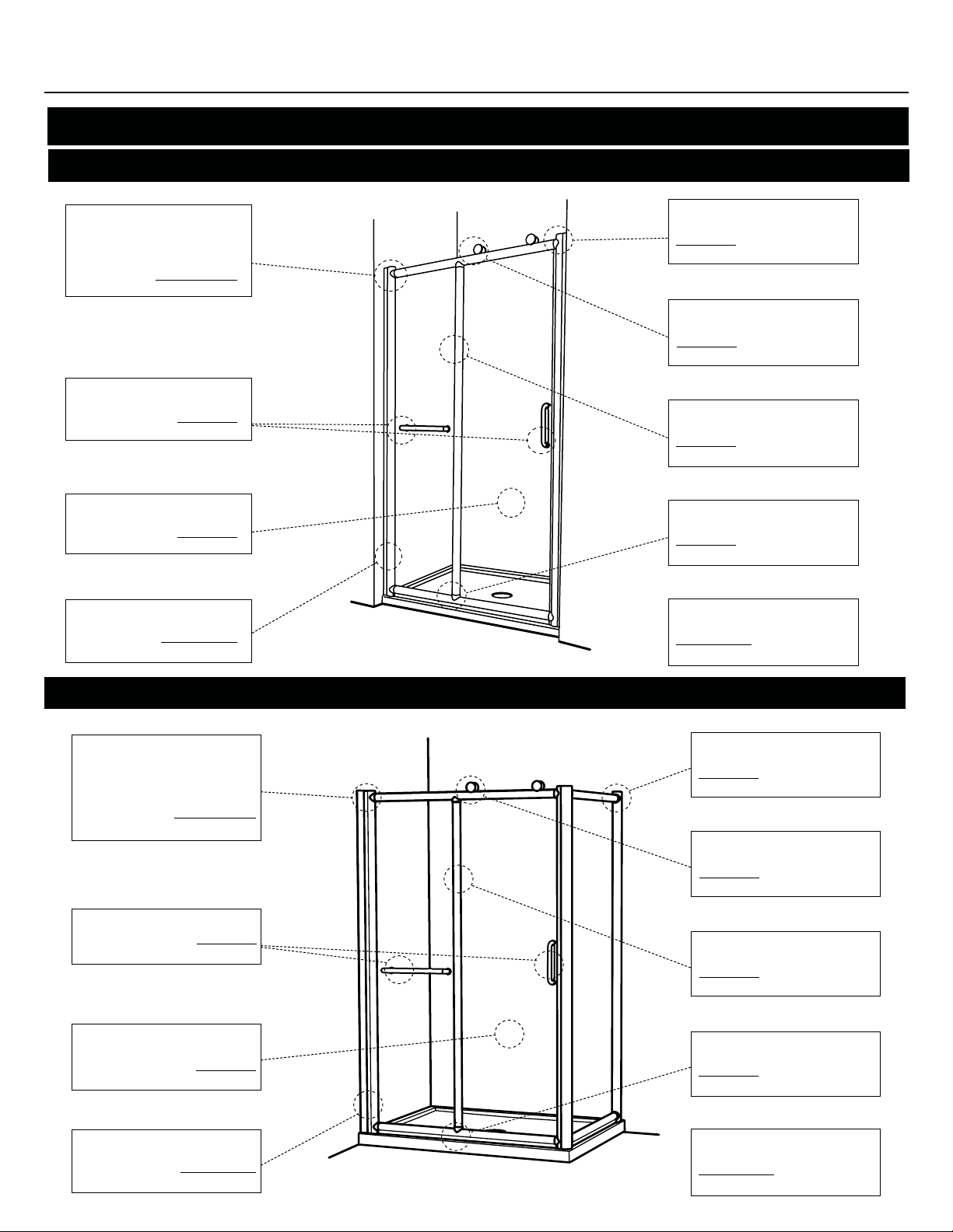
Nalu Panel and door
Nalu Panel and door with return panel
KN002
07.10

P
Follow the installation steps require for the model
Panel and door shower enclosure
Model
K-NS91Z-48 min: 46” / max:47 1/4 ”
K-NS91Z-60 min: 58 ” / max: 59 1/4”
K-NS91Z-72 min: 79 ” / max: 71 1/4”
Opening adjustment (min / max)
Panel and door with return panel
Model Opening adjustment (min / max) Return panel adjustment (min / max)
K-NS93Z-4836 min: 45 5/16” / max: 46” min: 33 5/16” / max: 34”
K-NS93Z-6036 min: 57 5/16” / max: 58” min: 33 5/16” / max: 34”
K-NS93Z-6042 min: 57 5/16” / max: 58” min: 40 1/8” / max: 40 13/16”
K-NS93Z-6048 min: 57 5/16” / max: 58” min: 46 1/8” / max: 46 13/16”
K-NS93Z-7236 min: 69 5/16” / max: 70” min: 33 5/16” / max: 34”
Please keep this manual and product code number for future reference and
replacement parts ordering if necessary.
GENERAL INSTRUCTIONS
• Read this manual carefully and completely before
proceeding.
• It is recommended that you wear safety glasses at
all times during the installation.
INSTALLATION OVER CERAMIC TILES
• Silicone should be used to seal the gap where the
ceramic tiles meet the panel.
• If your shower door is to be installed over ceramic
tiles, the tiles should lay completely under the wall
jamb.
NOTICE
• Caulking: no sealant is required inside the shower.
Unless otherwise stated.
• Some models are equipped with clear sealing
gaskets.
CARE FOR YOUR SHOWER DOOR
• Never use scouring powder pads or sharp instruments on metal pieces or glass panels. An occasional wiping down with a mild soap diluted in water
is all that is needed to keep the panels and aluminum parts looking new.
• We recommend wiping the glass panels with a
squeegee after each use.
Product are subject to change without
notice.
INSTALLATION MANUAL
FRM2-448 FRM2-460
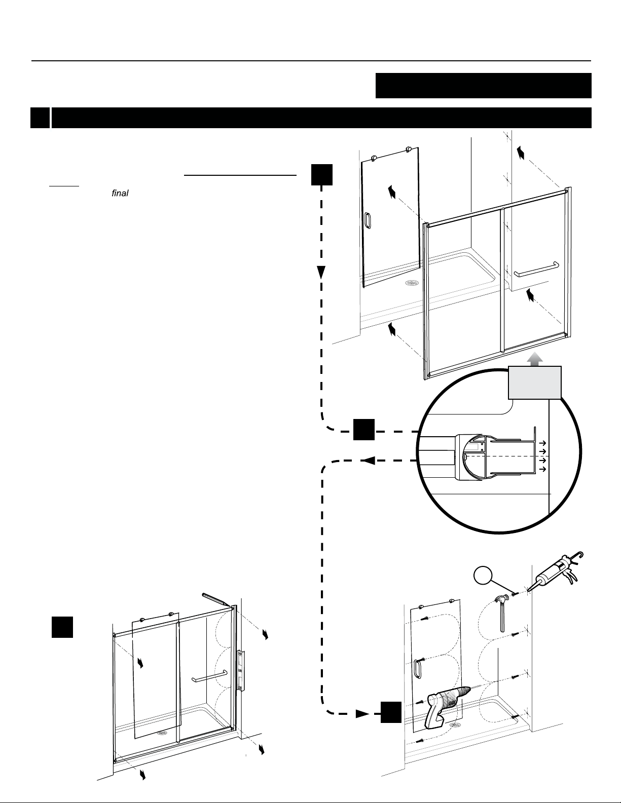
STEP 1
• Base positioning
• Frame assembly
• Fix panel
see page 14 - 15
STEP 2
• Handle and towel installation
see page 18
STEP 3
• Door assembly
see page 19
FRM2-472
INSTALLATION OF COMPONENTS
K-NS91Z-48-75 | K-NS91Z-60-75 | K-NS91Z-72-75
STEP 5
• Secure the wall jambs
see page 24
STEP 6
• Accessories installation
see page 27
STEP 7
• Door panel ajustement
see page 26
STEP 8
• Sealing
see page 28
STEP 4
• Wall jambs installation
see page 20-21
• Notes
see page 29-31
STEP 9
K-NS93Z-4836-75 | K-NS93Z-6036-75 | K-NS93Z-6042-75 | K-NS93Z-6048-75 | K-NS93Z-7236-75
STEP 1
• Base positioning
• Frame assembly
• Fix panel
see page 16 - 17
STEP 2
• Handle and towel installation
see page 18
STEP 3
• Door assembly
• Secure the wall jambs
see page 25
• Accessories installation
see page 27
• Door panel ajustement
see page 26
• Sealing
STEP 5
STEP 6
STEP 7
STEP 8
see page 19
STEP 4
• Wall jambs installation
see page 22-23
4
Return panel installed on right side shown
see page 28
STEP 9
• Notes
see page 29-31

TOOLS AND MATERIAL REQUIRED
INSTALLATION MANUAL
LONG NOSE LOCKING PLIER
1/4˝& 1/8˝ DRILL BITS
PENCIL
(X2)
SCREWDRIVERS
SILICONE
CUTTING PLIER
DRILL
BLOCK
TAPE MEASURE
LEVEL
*
To install the shower door on ceramic tiles, use a 1/4’’ drill bit for ceramic tiles.
MALLET
5/16” HEX NUT DRIVER
5

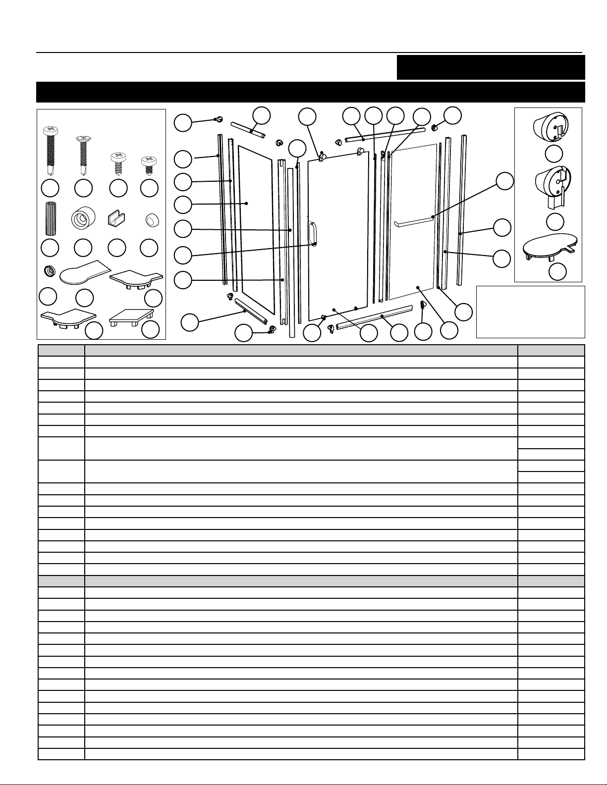
PARTS LISTING
INSTALLATION MANUAL
FRM2-448
K-NS91Z
HARDWARE
25
11
9
10
6
7
4
3
20 23 21 22
24
19
161718
27
14
12
13
28
29
26
2
1
ITEM PARTS QTY
1 WALL JAMB 2
2 EXPANDER 1
3 DOOR PANEL 1
4 SIDE PANEL 1
5 BOTTOM CONNECTOR 2
6 VERTICAL GASKET 2
7 VERTICAL 1
8 BOTTOM TRACK 1
9 TOP TRACK 1
10 DOOR SIDE GASKET 1
11 TOP CONNECTOR 2
12 MAGNETIC DOOR GASKET 1
13 MAGNETIC EXPANDER 1
14 SET OF HANDLES 1
15 TOWEL BAR 1
ITEM HARDWARE QTY
16 GLASS SUPPORT 4
17 WALL PLUG 8
18 SCREW CAP 16
19 BACK SCREW CAP 16
20 PAN SELF DRILLING SCREW #M4-35 16
21 PAN HEAD SCREW #M4-12 1
22 PAN CREW #M4-10 8
23 FLAT HEAD SCREW #M4-20 2
24 STOPPER 1
25 TOP WHEELS 2
26 BOTTOM WHEELS 2
27 COVER FOR THE EXPANDER 1
28 / 29 COVER FOR THE MAGNETIC EXPANDER 1
6
30 COVER FOR THE WALL JAMB 2
8
5
6
1
11
15
5
30
NOTE
XX REFERS TO THE MATERIAL FINISH
11- Bright Chrome
25 - Brushed Nickel
PARTS LISTING
INSTALLATION MANUAL
K-NS93Z
HARDWARE
22 25 23 24
19 18
21
26
29
31
ITEM
1
2
3
4
5
6
7
8
9
10
11
12
13
14
15
16
17
ITEM
18
19
20
21
22
23
24
25
26
27
28
29
30 / 31
32
7
33
20
32
30
11
13
15
16
14
9
27
9
10
7
12
1
2
11
6
11
17
1
5
2
33
NOTE
XX REFERS TO THE MATERIAL FINISH
8
5
28
3
PARTS
FRMRP2-3648
WALL JAMB
EXPANDER
DOOR PANEL
SIDE PANEL
BOTTOM CONNECTOR
VERTICAL GASKET
VERTICAL
BOTTOM TRACK
TOP TRACK
DOOR SIDE GASKET
TOP CONNECTOR
MAGNETIC DOOR GASKET
RETURN PANEL
CORNER MAGNETIC EXPANDER
CORNER MAGNETIC EXPANDER COVER
SET OF HANDLES
TOWEL BAR
QUINCAILLERIE - HARDWARE
GLASS SUPPORT
WALL PLUG
SCREW CAP
BACK SCREW CAP
PAN SELF DRILLING SCREW #M4-35
PAN HEAD SCREW #M4-12
PAN CREW #M4-10
FLAT HEAD SCREW #M4-20
STOPPER
TOP WHEELS
BOTTOM WHEELS
COVER FOR THE EXPANDER
COVER FOR THE MAGNETIC EXPANDER
COVER FOR THE WALL JAMB
COVER FOR THE CORNER WALL JAMB
5
8
6
11- Bright Chrome
4
25 - Brushed Nickel
QTY
2
2
1
1
4
4
1
1
1
1
1
1
4
1
1
1
1
1
1
QTY
8
8
16
16
24
1
8
2
1
2
2
2
2
2
2

INSTALLATION MANUAL
K-NS91Z
1
Model
K-NS91Z-48 min: 46” / max: 47 1/4”
K-NS91Z-60 min: 58” / max: 59 1/4”
K-NS91Z-72 min: 70” / max: 71 1/4”
* Tolerance on dimensions ± 1/8” (3mm
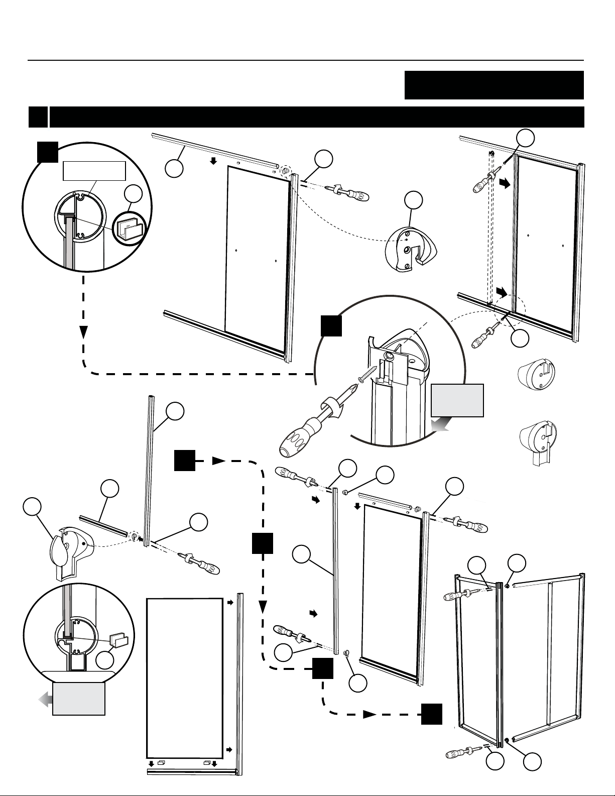
1a.
Use a measuring tape to mark the center of the
threshold of the base.
1b.
Using 1 3/8” screws (2), fasten the expander to
the bottom track by placing the bottom connector between the bottom track and expander.
1c.
Place glass clips (2) on the bottom edge of the
panel and slide it into the expander and
bottom track.
Opening adjustment (min / max)
)
1a
POSITIONNING ON THE THRESHOLD
Opening
See table
INTERIOR
SHOWER SIDE
Place glass clips (2) on the top edge of the
1d.
panel. Fasten the top track using 1 3/8” screws
(2) by placing the top connector between the
top track and expander.
1e.
Insert the vertical column onto the
and screw into the top and bottom track using
the 3/4” screws (2).
Screw the magnetic expander to the top and
1f.
bottom tracks using the 1 3/8” screws (4) by
placing the two connectors in between.
panel
2
8
1b
5
20
8

INSTALLATION MANUAL
K-NS91Z
1
1c
BOTTOM TRACK
16
4
1d
FIXED PANEL INSTALLATION
20
16
11
20
11
23
1e
7
INTERIOR
SHOWER SIDE
20
5
TOP CONNECTOR
23
BOTTOM CONNECTOR
9

INSTALLATION MANUAL
INSTALLATION MANUAL
INSTALLATION MANUAL
K-NS93Z
1
1
1a.
POSITIONNEMENT SUR LE SEUIL DE LA BASE / POSITIONNING ON THE THRESHOLD
Use a measuring tape to mark the center of the
threshold of the base.
Using 1 3/8” screws (x2), fasten the expander to
1b.
the bottom track by placing the bottom connec
tor between the bottom track and expander.
1c.
Place glass clips (x2) on the bottom edge of the
panel and slide them into the expander
and bottom track.
1d.
Place glass clips (x2) on the top edge of the
panel. Fasten the top track using 1 3/8” screws
(x2) by placing the top connector between the
top track and expander.
POSITIONNING ON THE BASE
INTERIOR
SHOWER SIDE
-
Side opening
See table
Front opening
See table
1a
BOTTOM TRACK
INTERIOR
SHOWER SIDE
10
10
1e.
Insert the vertical column onto the
and screw into the top and bottom track using
the 3/4” screws (x2).
1f.
Repeat step 1b, 1c and 1d with the return panel
parts. Assemble the in-line frame with the return
panel frame using the 1 3/8” screws (x8) by
placing the two connectors in between. Hide the
screws on the corner magnetic expander with
the corner magnetic expander cover.
* Tolerance on dimensions ± 1/8” (3mm)
panel
2
18
8
1b 1c
5
Model
K-NS93Z-4836 min: 45 5/16” / max: 46” min: 33 5/16” / max: 34”
K-NS93Z-6036 min: 57 5/16” / max: 58” min: 33 5/16” / max: 34”
K-NS93Z-6042 min: 57 5/16” / max: 58” min: 40 1/8” / max: 40 13/16”
K-NS93Z-6048 min: 57 5/16” / max: 58” min: 46 1/8” / max: 46 13/16”
K-NS93Z-7236 min: 69 5/16” / max: 70” min: 33 5/16” / max: 34”
Opening adjustment (min / max)
22
Return panel adjustment (min / max)
INSTALLATION MANUAL
INSTALLATION MANUALINSTALLATION MANUAL
K-NS93Z
1
1d
1d
BOTTOM TRACK
9
18
22
FIXED & RETURN PANEL ASSEMBLY
25
11
1e
25
14
INTERIOR
SHOWER SIDE
TOP CONNECTOR
1f
8
5
22
22
11
22
BOTTOM CONNECTOR
1f
INTERIOR
SHOWER SIDE
18
2
22
22
1f
5
11
1f
22
5
11

INSTALLATION MANUAL
K-NS91Z, K-NS93Z
2
2a.
Install the handle as shown.
2b.
Using an hex key to install the towel barr as shown.
2A-1
HANDLE INSTALLATION
2A
2A-2
12
2B-1
INTERIOR
SHOWER SIDE
2B-2
INTERIOR
SHOWER SIDE
2B
INTERIOR
SHOWER SIDE

INSTALLATION MANUAL
3
3a.
Use a mallet to install the magnetic gasket
and the side gasket on the door panel.
Ensure the textured side of the glass panel
is located towards the outside of the shower.
3b.
Install the rollers on the door panel so that
the rollers point towards the outside of the
shower. The vertical handle must always be
on the opening side of the door towards the
outside of the shower.
DOOR ASSEMBLY
MAGNETIC GASKET
INTERIOR
SHOWER SIDE
SIDE GASKET
K-NS91Z, K-NS93Z
3a
3c.
Install the bottom sliders on the door panel
while placing the hooks towards the outside
of the shower. Place the bottom slider cap
over the screw.
INTERIOR
SHOWER SIDE
INTERIOR
SHOWER SIDE
3b
3c
13
INSTALLATION MANUAL
K-NS91Z
4
4a.
Place the door inside the shower by protecting the surface of
the base. Insert the wall jambs into the expander and place
the frame in its
4b.
Level the shower frame. Mark the drilling location of the holes
for the wall jamb then remove the frame temporarily.
With a 1/4” drill bit, drill 8 holes into the wall on the side of
4c.
the opening of the door using the marks done in the previous
step. Place a drop of silicone in each hole and insert 8 wall
plugs.
position temporaraily
4a
WALL JAMB INSTALLATION
INTERIOR
SHOWER SIDE
Fasten the wall jamb on the side of the opening of the door by
4d.
using 1 3/8” (4) screws and the wall plugs already installed .
Place the screw caps(4).
4e
Insert the second wall jamb.Reposion the frame onto the
center of the threshold.
4f
Screw the wall jamb into the wall plugs already installed by
using screws 1 3/8” (4) and place the screw caps .
4b
4b
17
4c
14
3D

INSTALLATION MANUAL
K-NS91Z
4
WALL JAMB INSTALLATION
A
Slide
Rotate
B
4e
4d
4e
4f
19
20
INTERIOR
SHOWER SIDE
INTERIOR
SHOWER SIDE
18
4f
INTERIOR
SHOWER SIDE
15

INSTALLATION MANUAL
K-NS93Z
4
4a.
Place the wall jambs against the wall so that
the holes are located towards the interior of the
shower. Center the opening of the wall jamb on
the line marked previously. Ensure verticality
with a level. Mark the holes position with pencil
using the holes of the wall jamb for reference.
Drill the holes in the wall with Ø1/4’’ drill bit.
4b.
To install the shower door on ceramic tiles, use
a Ø1/4’’ drill bit for ceramic tiles.
WALL JAMB INSTALLATION
4a
4c.
Insert one drop of silicone in each hole bored
in the wall before inserting the wall plug (x8) on
both side.
4d.
Screw the two wall jambs into the wall plugs
already installed in the wall by using screws
1 3/8’’ (x8). Ensure verticality with the level.
Put screw caps on the screw heads.
4e.
Insert the wall jambs into the expander and
place temporairaly the frame centred on the
threshold line marked previously.
19
4c
16
4b

INSTALLATION MANUAL
K-NS93Z
4
20
21
22
INTERIOR
SHOWER SIDE
WALL JAMB INSTALLATION
4d
4e
INTERIOR
SHOWER SIDE
17

INSTALLATION MANUAL
K-NS91Z
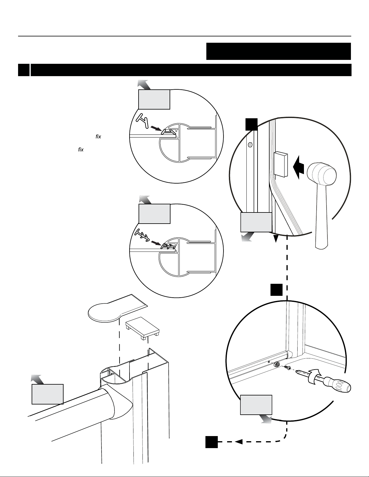
5
5a.
Level the top track and bottom track, by
using locking pliers . Clamp the expanders
with their wall jambs.*
5b.
Secure the expanders with the wall jambs
by using the 3/8” self drilling screws (6) and
screw caps (6).
SECURE THE WALL JAMBS
5a
18
5b
19
22
INTERIOR
SHOWER SIDE
18
*
COVER THE PLIER’S TEETH BEFOREHAND TO
AVOID SCRATCHING THE ALUMINUM PARTS.
INTERIOR
SHOWER SIDE

INSTALLATION MANUAL
5
5a.
Level the top track and bottom track, by
using locking pliers . Clamp the expanders
with their wall jambs.*
5b.
Secure the expanders with the wall jambs
by using the 3/8” self drilling screws (x6) and
screw caps (x6).
5a
SECURE THE WALL JAMBS
K-NS93Z
5b
21
24
INTERIOR
SHOWER SIDE
20
*
COVER THE PLIER’S TEETH BEFOREHAND TO
AVOID SCRATCHING THE ALUMINUM PARTS.
INTERIOR
SHOWER SIDE
19
INSTALLATION MANUAL
6
6a.
Using a mallet and block install
the two vertical gaskets. One
between the expander and
panel, the second between the
vertical column and
gasket must be installed inside the
shower.
6b.
The bumper is located on the
bottom track opposite the opening
of the door. Use a screw 1/2” to
install the bumper.
panel. The
K-NS91Z, K-NS93Z
ACCESSORIES INSTALLATION
INTERIOR
SHOWER SIDE
6a
Clear Glass
INTERIOR
SHOWER SIDE
INTERIOR
SHOWER SIDE
6c.
Place the expander caps on the
expanders.
INTERIOR
SHOWER SIDE
Paris Point Glass
INTERIOR
SHOWER SIDE
6b
20
6c

INSTALLATION MANUAL
K-NS91Z, K-NS93Z
7
7a.
Place the top rollers of the door panel on the
top track and push on the bottom sliders to
engage them into the bottom track.
7b.
Slightly unscrew the nut of the top rollers of
the door panel this will allow you to adjust
the door. Screw it back by ensuring verticality
with the level.
7c
Place the expander caps on the expanders.
INTERIOR
SHOWER SIDE
DOOR PANEL ADJUSTEMENT
7a
INTERIOR
SHOWER SIDE
INTERIOR
SHOWER SIDE
7b
21

INSTALLATION MANUAL
8
8a.
Silicone the outside of the frame between the
wall and the wall jamb, along the bottom rail,
below the
return panel if applicable.
8b.
Wait 24 hours before using the shower to allow the silicon to dry.
panel and at the bottom of the
8a
INTERIOR
SHOWER SIDE
K-NS91Z, K-NS93Z
SEALING
22
8b
HOURS

INSTALLATION MANUAL
K-NS91Z, K-NS93Z
9
NOTES
23
 Loading...