

Page 1
pcIPcard
TM
IP9001
User Manual
2005-06-09
Page 2

FCC Information
Note: This equipment has been tested and found to comply with the limits for a Class B
digital device, pursuant to Part 15 of the FCC Rules. These limits are designed to provide
reasonable protection against harmful interference in a residential installation. This
equipment generates, uses and can radiate radio frequency energy, and if not installed
and used in accordance with the instruction manual, may cause interference to radio
communications. However, there is no guarantee that interference will not occur in a
particular installation. If this equipment d oes cause harmful interference to radio or
television reception, whic h ca n be det e rmined by turning the equipment off a nd on, the
user is encouraged to try to correct the interference by one or more of the following
measures:
M Reorient or relocate the receiving antenna;
M Increase the separation between the equipment and receiver;
M Connect the equipment into an outlet on a circuit different from that which the
receiver is connected;
M Consult the dealer or an experienced radi o/ t e l e vi si on t echni ci an for he l p.
© Copyright 2005 ALTUSEN® PAPE-0252-1AXG
All brand names and trademarks are the registered property of their respective owners.
2005-06-09
Page 3

Package Contents
Standard Components
The standard IP9001 package consists of:
M 1 IP9001 Card
M 1 USB Cable
M 1 Custom Made Feature Connector Cable
M 1 Power Cord
M 1 AC Adapter
M 1 Software CD
M 1 User Manual
M 1 Quick start guide
M 1 Warranty registrati on c a rd
Optional Components
The following components do not come wit h your IP9001 card. You m ust order these
components separately.
M internal modem daughterboard
M internal battery bac kup wi t h ba t tery clip
Note: The opti ona l modem is NOT designed for Console Redirect i on. While it is
possible to do Console Redirection with it, the performa nc e is ext re m ely sl ow
and debilitating to system operations.
Check to make sure that all of the components are present and in good order. If
anything is missing, or was damaged i n shi ppi ng, contact your dealer.
Read this manual thoroughly and follow t he i nstallation and operation procedures
carefully to prevent any damage to the switch or to any othe r de vices on the IP9001
installation.
iii
2005-06-09
Page 4

Contents
Chapter 1
Introduction
Features . . . . . . . . . . . . . . . . . . . . . . . . . . . . . . . . . . . . . . . 1
Chapter 2
Installation
Before you Begin . . . . . . . . . . . . . . . . . . . . . . . . . . . . . . . . . 5
Avoid Electro-Static Discharge (ESD) . . . . . . . . . . . . . . . . . . . . 5
Installation Overview . . . . . . . . . . . . . . . . . . . . . . . . . . . . . 6
1. Unpack the IP9001 card (and check jumper settings) . . . . . . . . . . . . . 7
Card Layout Diagram . . . . . . . . . . . . . . . . . . . . . . . . . . . . . 7
MAC Address . . . . . . . . . . . . . . . . . . . . . . . . . . . . . . . . . 7
Check the Jumpers . . . . . . . . . . . . . . . . . . . . . . . . . . . . . . 8
2. Install the Optional Battery and Battery Clip . . . . . . . . . . . . . . . . . 11
BBU (Battery Backup Unit) Installation . . . . . . . . . . . . . . . . . . 11
Charging the Battery Pack . . . . . . . . . . . . . . . . . . . . . . . . . 12
Changing the Battery Pack . . . . . . . . . . . . . . . . . . . . . . . . . 13
Battery Disposal . . . . . . . . . . . . . . . . . . . . . . . . . . . . . . . 13
3. Install the Optional Modem Daughterboard . . . . . . . . . . . . . . . . . 14
J3 - Service Connector . . . . . . . . . . . . . . . . . . . . . . . . . . . 14
J4 - JTAG ICE Connector . . . . . . . . . . . . . . . . . . . . . . . . . 14
J5 - IPMB (Intelligent Platform Management Bus) . . . . . . . . . . . . 15
IPMB (Intelligent Platform Management Bus) . . . . . . . . . . . . . . 15
J9 - IP9001 Feature Connector . . . . . . . . . . . . . . . . . . . . . . . 16
JP2 - Serial Port Connector . . . . . . . . . . . . . . . . . . . . . . . . 17
JP3 - Service Connector . . . . . . . . . . . . . . . . . . . . . . . . . . 17
JP4 and JP5 - Chassis/Motherboard Power Switch . . . . . . . . . . . . . 17
JP6 - IP9001 Reset Button . . . . . . . . . . . . . . . . . . . . . . . . . 17
JP7 and JP8 - Chassis/Motherboard Reset Switch . . . . . . . . . . . . . 17
5. Connect External Cables . . . . . . . . . . . . . . . . . . . . . . . . . . . 18
7. Install the Operating System and IP9001 Drivers . . . . . . . . . . . . . . . 19
Installing Virtual Floppy Drivers on Microsoft® Windows . . . . . . . . 19
8. Install the Windows Software Components . . . . . . . . . . . . . . . . . . 22
9. Setup Your Client Internet Browser . . . . . . . . . . . . . . . . . . . . . . 25
10. Connecting From a Client System . . . . . . . . . . . . . . . . . . . . . . 29
11. Load the SDR and Soft Processor (SP) File . . . . . . . . . . . . . . . . . 34
iv
2005-06-09
Page 5

Chapter 3
Locating the IP9001 Card
Overview . . . . . . . . . . . . . . . . . . . . . . . . . . . . . . . . . . . . . 37
Locating the IP9001 Card . . . . . . . . . . . . . . . . . . . . . . . . . . . . 37
Usage . . . . . . . . . . . . . . . . . . . . . . . . . . . . . . . . . . . . . . . 40
Chapter 4
Browser Operation
Overview . . . . . . . . . . . . . . . . . . . . . . . . . . . . . . . . . . . . . 41
Logging In . . . . . . . . . . . . . . . . . . . . . . . . . . . . . . . . . . . . 41
Chapter 5
The Manage Menu
Overview . . . . . . . . . . . . . . . . . . . . . . . . . . . . . . . . . . . . . 43
Remote Console . . . . . . . . . . . . . . . . . . . . . . . . . . . . . . . . . 44
Console Redirection . . . . . . . . . . . . . . . . . . . . . . . . . . . . . . . 45
Internet Explorer Setup . . . . . . . . . . . . . . . . . . . . . . . . . . . 45
Starting Redirection . . . . . . . . . . . . . . . . . . . . . . . . . . . . . 45
The Console Redirection Screen . . . . . . . . . . . . . . . . . . . . . . 47
The Console Redirection Toolbar . . . . . . . . . . . . . . . . . . . . . 50
Toolbar Icons . . . . . . . . . . . . . . . . . . . . . . . . . . . . . . . . 51
CD Drive Redirection . . . . . . . . . . . . . . . . . . . . . . . . . . . 52
Floppy Drive Redirection . . . . . . . . . . . . . . . . . . . . . . . . . . 54
Floppy Image Creation . . . . . . . . . . . . . . . . . . . . . . . . . . . 56
Transfer A Floppy Image To Floppy Disk . . . . . . . . . . . . . . . . . 59
Stopping Console Redirection . . . . . . . . . . . . . . . . . . . . . . . 62
Remote Power Control . . . . . . . . . . . . . . . . . . . . . . . . . . . . . . 63
Upgrade Firmware . . . . . . . . . . . . . . . . . . . . . . . . . . . . . . . . 64
Reset the IP9001 . . . . . . . . . . . . . . . . . . . . . . . . . . . . . . . . . 69
Remote Console Hotkey Combinations . . . . . . . . . . . . . . . . . . . . . 71
Chapter 6
The Configure Menu
Overview . . . . . . . . . . . . . . . . . . . . . . . . . . . . . . . . . . . . . 73
Users . . . . . . . . . . . . . . . . . . . . . . . . . . . . . . . . . . . . . . . 74
Adding Users . . . . . . . . . . . . . . . . . . . . . . . . . . . . . . . . 75
Removing Users . . . . . . . . . . . . . . . . . . . . . . . . . . . . . . 76
Viewing and Editing Users . . . . . . . . . . . . . . . . . . . . . . . . . 77
Network . . . . . . . . . . . . . . . . . . . . . . . . . . . . . . . . . . . . . 78
Firewall . . . . . . . . . . . . . . . . . . . . . . . . . . . . . . . . . . . . . 79
Alert Notification . . . . . . . . . . . . . . . . . . . . . . . . . . . . . . . . 81
Date & Time . . . . . . . . . . . . . . . . . . . . . . . . . . . . . . . . . . . 82
2005-06-09
v
Page 6

Serial Port . . . . . . . . . . . . . . . . . . . . . . . . . . . . . . . . . . . . 83
SSL Certificate . . . . . . . . . . . . . . . . . . . . . . . . . . . . . . . . . . 84
PMCP File Upload . . . . . . . . . . . . . . . . . . . . . . . . . . . . . . . . 85
IPMI Configuration . . . . . . . . . . . . . . . . . . . . . . . . . . . . . . . 86
Server OS Monitoring and Recovery . . . . . . . . . . . . . . . . . . . . . . 87
PPP Configuration . . . . . . . . . . . . . . . . . . . . . . . . . . . . . . . . 88
Chapter 7
The View Menu
Overview . . . . . . . . . . . . . . . . . . . . . . . . . . . . . . . . . . . . . 89
Card Health . . . . . . . . . . . . . . . . . . . . . . . . . . . . . . . . . . . . 90
Event Log . . . . . . . . . . . . . . . . . . . . . . . . . . . . . . . . . . . . 90
Server Health . . . . . . . . . . . . . . . . . . . . . . . . . . . . . . . . . . . 91
General Information . . . . . . . . . . . . . . . . . . . . . . . . . . . . . . . 92
Versions . . . . . . . . . . . . . . . . . . . . . . . . . . . . . . . . . . . 92
Features . . . . . . . . . . . . . . . . . . . . . . . . . . . . . . . . . . . 93
Detailed Versions . . . . . . . . . . . . . . . . . . . . . . . . . . . . . . 94
Last Saved Crash Screen . . . . . . . . . . . . . . . . . . . . . . . . . . . . . 95
Appendix A
Feature Cable Layout
Appendix B
API Configuration Program
Overview . . . . . . . . . . . . . . . . . . . . . . . . . . . . . . . . . . . . . 99
Setup . . . . . . . . . . . . . . . . . . . . . . . . . . . . . . . . . . . . . . . 99
Configuration . . . . . . . . . . . . . . . . . . . . . . . . . . . . . . . . . 101
The User Manager . . . . . . . . . . . . . . . . . . . . . . . . . . . . 101
Network Configuration . . . . . . . . . . . . . . . . . . . . . . . . . . 105
Advanced Configuration . . . . . . . . . . . . . . . . . . . . . . . . . 106
Appendix C
Remote Recovery Application
Overview . . . . . . . . . . . . . . . . . . . . . . . . . . . . . . . . . . . . 107
Flashing the Card . . . . . . . . . . . . . . . . . . . . . . . . . . . . . . . 109
Appendix D
Troubleshooting
Screen Distortion . . . . . . . . . . . . . . . . . . . . . . . . . . . . . . . . 113
BMC Not Responding . . . . . . . . . . . . . . . . . . . . . . . . . . . . . 114
Connot Manage Host System’s Power Remotely . . . . . . . . . . . . . . . 115
Unexpected Errors After Flashing New Firmware . . . . . . . . . . . . . . 116
vi
2005-06-09
Page 7

Appendix E
Modem Daughterboard
Overview . . . . . . . . . . . . . . . . . . . . . . . . . . . . . . . . . . . . 117
Before You Begin . . . . . . . . . . . . . . . . . . . . . . . . . . . . . . . 118
Avoid Electrostatic Discharge (ESD) . . . . . . . . . . . . . . . . . . 118
Installation . . . . . . . . . . . . . . . . . . . . . . . . . . . . . . . . . . . 119
Appendix F
Port Usage
Port Usage Table . . . . . . . . . . . . . . . . . . . . . . . . . . . . . . . . 121
Appendix G
MAC Address Map
Appendix H
Linux 7.x Considerations
Overview . . . . . . . . . . . . . . . . . . . . . . . . . . . . . . . . . . . . 125
Preparation . . . . . . . . . . . . . . . . . . . . . . . . . . . . . . . . . . . 125
Mouseconfig . . . . . . . . . . . . . . . . . . . . . . . . . . . . . . . 125
BIOS Settings . . . . . . . . . . . . . . . . . . . . . . . . . . . . . . . 125
USB Keyboard . . . . . . . . . . . . . . . . . . . . . . . . . . . . . . . . . 125
USB Mouse . . . . . . . . . . . . . . . . . . . . . . . . . . . . . . . . . . 126
Appendix I
Specifications
2005-06-09
vii
Page 8

Conventions
This manual uses the following conventions:
Courier
[ ]
Indicates text that you should key in.
Indicates keys you should press. For example, [Enter] means
to press the Enter key. If keys need to be chorded, they
appear together in the same bracket with a plu s s ig n betw een
them: [Ctrl+Alt].
1.
M
>
Numbered lists represent procedures with sequential steps.
Bullet lists provide information
Indicates selecting an option on a menu. For example, Start >
Run means to open the Start menu, and then select Run.
Indicates critical information.
Getting Help
For additional help, advice, and informati on, AL TUSEN provides several support
options. If you need to contact ALTUSEN technical support wit h a problem , pl ease
have the following informati on re ady beforehand:
M Product model number, serial num ber, and date of purchase.
M Your computer configuration, including operating syst em, re vi si on leve l,
expansion cards, and software.
M Any error messages displayed at the time the error occurred.
M The sequence of operations that l e d up t o t he error.
M Any other information you feel may be of help.
viii
2005-06-09
Page 9

ALTUSEN Technical Support
North America Technical
Phone Support
International Technical
Phone Support
Email Support Email your questions and concerns to:
Online Troubleshooting The ALTUSEN support website:
Online Documentation User Manuals are available electronically at the
Software Updates Download the latest drivers and firmware for your
Registered ALTUSEN product owners are entitled
to telephone technical support. Call the ALTUSEN
Technical Support Center: 949-453-8885.
1. Contact your local dealer.
2. Call the ALTUSEN Technical Support Center:
(886-2) 8692-6959.
http://www.altusen.com/support
provides online troubeshooting that describes the
most commonly encountered problems and offers
possible solutions to them.
ALTUSEN support website:
http://www.altusen.com/support
product from the ALTUSEN support website:
http://www.altusen.com/support
Product Information
For information about all of ALTUSEN’s products and how they can help you
connect without limits, visit ALTUSEN on the web.
ALTUSEN Authorized Resellers
ALTUSEN provides the following ways to find an authorized reseller in your area:
M In the United States of America, call: 866-ALTUSEN (258-8736)
M In Canada and South America, call: 949-453-8885
M In all other locations, call: 886-2-8692-6789
M Visit ALTUSEN on the web at http://www.altusen.com for a list of locations and
telephone numbers
2005-06-09
ix
Page 10

Notes:
x
2005-06-09
Page 11

Chapter 1.
Introduction
Features
Feature Description
Key Feature M 100% out-of-band
Soft Processor M plugs into a mission critical server
Remote Client M industry standard Internet browser (any JavaScript 1.2
Processor System
On Chip (SOC)
Memory M 32 megabyte PC-133 MHz SDRAM standard (soldered on
Flash M 16 bit, 16 megabyte flash ROM (soldered on PCB, you
Ethernet LAN M integrated SOC 10/100 MAC
On-Board Modem
+ DAA (Optional)
I2C Controller
Hardware Monitor
(OEM version
feature)
Power Supply M switching logic between optional 6 V wall adapter, 5 V PCI,
Battery Backup
(Optional)
Form Factor M half-size standard PCI card
M 100% operating system independent
M half-sized PCI form factor plugs into any PCI slot
capable)
M manage the server from anywhere in the world
M SSL v3 for secure connection
M 32-Bit 266 MHz ~ 400 MIPS MMU
M 16 K I-cache
M 16 K D-cache
PCB, you cannot upgrade or remove)
cannot upgrade or remove)
M external level one 10/100 BASE-TX Ethernet
M 56K socket modem (not designed to support Console
Redirection)
M ambient temperature monitoring
M PCI voltage monitoring
M card internal voltage monitoring
M battery voltage monitoring
M RTC
M external RTC for time stamp of events
3.3 V PCI, and optional on-board battery
M 900 mAh LION battery provides 30 minutes of battery backup
in case of host system or optional wall adapter power failure
2005-06-09
1
Page 12

Feature Description
Environmental
Specifications
Monitoring M IPMI 1.5 compliant (OEM version feature)
Communication M 10/100 megabit Ethernet LAN
USB Device
Controller for
Mouse/Keyboard
USB Device
Controller for
CD-ROM
USB Device
Controller for FDD
USB Hub M USB 2.0 hub
Serial Ports X 3 M debug port
Debug Support M Jtag ICE
Alert Notification M SNMP trap up to eight destinations
Console
Redirection
M storage temperature: -20 degrees to 80 degrees C
M relative humidity: 5 to 80 percent non-condensing @
40 degrees
M operating temperature: 0 to 45 degrees C
M vibration: 2.5G acceleration over 2000 Hz sine wave,
2oct/mian sine sweep
M shock: 20G; 11 msec duration, half-sine shock sweep
M I2C sensors (OEM version feature)
M SDR and Soft Processor (SP) file support for easy
customization (OEM version feature)
M OEM specific
M 56K modem (optional); not designed to support console redirection
M TCP/IP
M DHCP enabled
M SNMP
M web based interface
M USB 1.1 device controller
M USB 2.0 device controller
M USB 1.1 device controller
M RS485
M one external
M numeric and alphanumeric paging (when optional modem is
installed)
M email notification
M via 10/100 megabit Ethernet LAN
M up to three multiple redirection sessions
M up to 15 screens per second high speed redirection
hardware engine
M no overhead on the host system, complete operating sytem
independence
M redirect BIOS screens and setup screens
M seamless text and graphics transition
2
2005-06-09
Page 13

Feature Description
Security M SSL (Secured Socket Layer) 3.0 (Pass-phrase encrypted
Virtual Boot M USB 2.0 CD-ROM
Host Side
Operating System
Support
OEM
Development Kit
Platform
Management
Configuration
Program (PMCP)
certificates are not supported)
M DAA (Digestive Authentication Access)
M MD-5
M USB floppy
M supports boot to image
M allows remote operating system boot up and installation
Note: For information on how to create a bootable CD, visit
nero.com or roxio.com. You can do a search on how to create
a bootable CD using their products. You can also consult your
CD writer’s documentation.
M Windows 2000/2003/XP and above
M RedHat 8.0 and above
available
2005-06-09
3
Page 14

Notes:
4
2005-06-09
Page 15

Before you Begin
Avoid Electro-Static Discharge (ESD)
Electrostatic discharge (ESD) can damage the IP9001 card and other
system components. Keep your IP9001 card in its antistatic bag until it is
ready to be installed. Avoid contact wi t h any com pone nt or conne ct or on
any adapter card, printed circuit board, or memory module. Handle these
components by the mounting bracket .
Perform all unpacking and installation proc edure s on a ground conne ct ed
antistatic mat. Wear an antistatic wristband grounded at the same point as
the antistatic mat. You can also use a sheet of conduct i ve al uminum foil
grounded through a one megaohm resistor inst ead of the antistatic mat.
Similarly, a strip of conductive aluminum foil wrapped around the wrist
and grounded through a one megaohm resistor serve s t he same purpose as
a wristband.
Chapter 2.
Installation
2005-06-09
5
Page 16

Installation Overview
Installation of the IP9001 card takes the following steps:
Step Action
1
2
3
4
5
6
7
8
9
10
11
The following sections describe how t o pe rform these steps.
Unpack the IP9001 card (and check jumper settings)
Install the optional battery and battery clip
Install the optional modem daughterboard
Plug the IP9001 card into the host system and attach internal cables
Connect external cables
Confirm the motherboard’s BIOS settings
Install the operating system and IP9001 card’s drivers
Install all IP9001 Windows Software Components
Setup your client system’s Internet browser
Connect to the IP9001 from a client system
Load the IP9001 SDR and Soft Processor (SP) File for your
motherboard or server board model (OEM version feature)
6
2005-06-09
Page 17
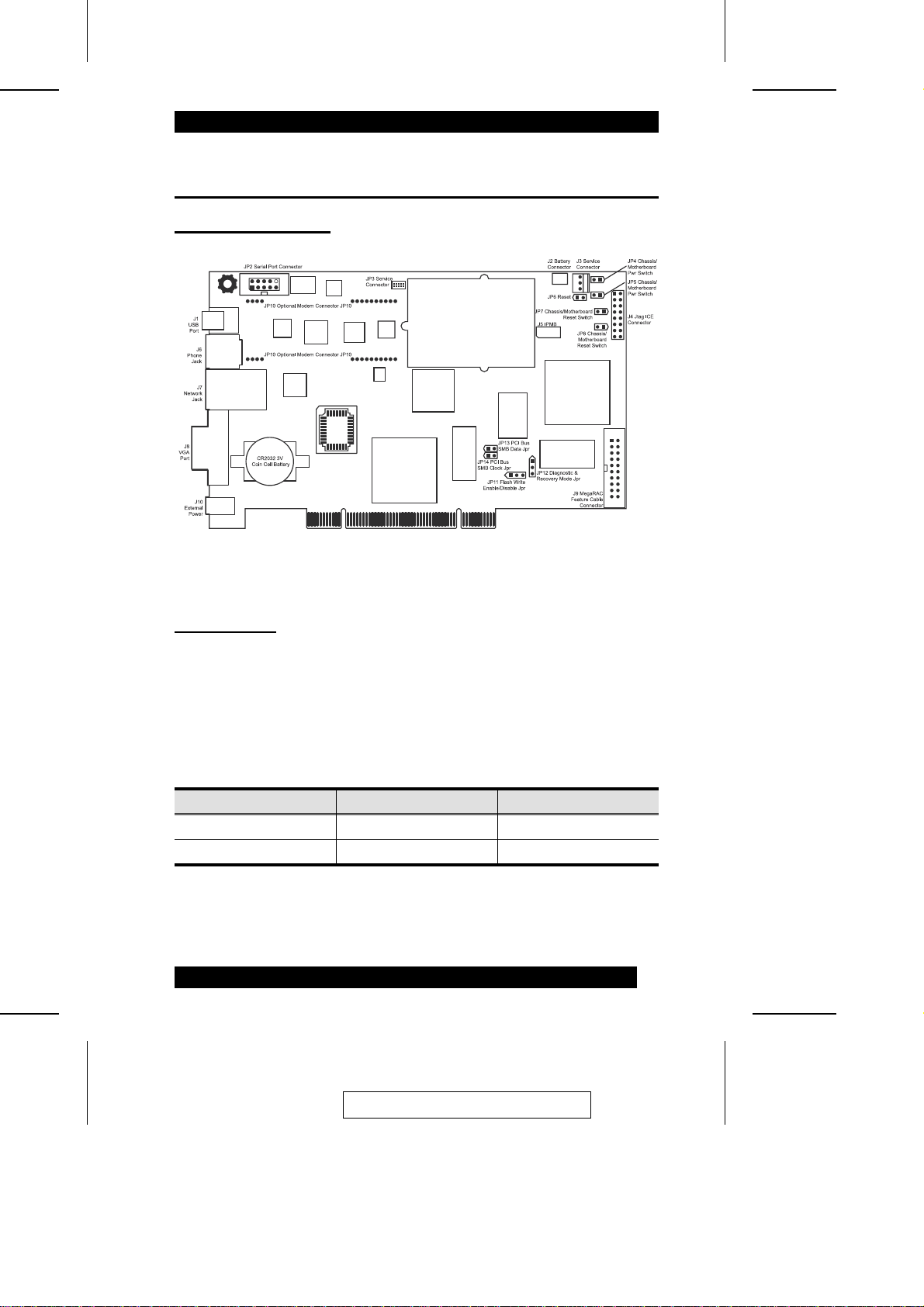
1. Unpack the IP9001 card (and check jumper settings)
Card Layout Diagram
IP9001
MAC Address
Each IP9001 card has a unique MAC address. The MAC address is the only way to
distinguish one IP9001 card from another when you run program s suc h as Re m ot e
Recovery Application (RRA) and RacTrendsSeek Locator. For reference, you can
write your IP9001 card’s MAC address in the table below or in Appendix H, MAC
Address Map. Use the first line in the table as an example.
MAC Address Location Description
00-40-D9-02-9B-3C Server Room, Rack 3-4 RH 9.0, Mail Server
7
2005-06-09
Page 18

Check the Jumpers
Check that the card’s jumpers match t he de sc ription in the following table:
Jumper Setting
JP4 Pins 1 and 2: Open
JP5 Pins 1 and 2: Open
JP6 Pins 1 and 2: Open
JP7 Pins 1 and 2: Open
JP8 Pins 1 and 2: Open
JP11 Pins 1 and 2: Shorted
JP12 Pins 1, 2, and 3: Open
JP13 If your host system’s motherboard supports 12C on the PCI slots,
JP14 If your host system’s motherboard supports 12C on the PCI slots,
JP4 and JP5 - Chassis/Motherboard Power Switch:
Verify that there is no jumper on JP4 and JP5. These two headers are to be used with
a cable, not a jumper.
Short pins 1 and 2. If not, see that pins 1 and 2 are Open.
Short pins 1 and 2. If not, see that pins 1 and 2 are Open.
JP6 - IP9001 Reset Button:
You can temporarily short this jumper to reset your IP9001 card. For norm al
operations, verify that there is no jumper on JP6.
Pin Description
1
Ground
2
Reset #
8
2005-06-09
Page 19

JP7 and JP8 - Chassis/Motherboard Reset Switch:
Verify that there is no jumper on JP7 and JP8. These two headers are to be used with
a cable, not a jumper.
JP11 - Flash Write Enable/Disable:
You can write-protect your IP9001 card’s firmware so that it cannot be flashed. By
default, pins one and two are shorted so tha t you can flash the firmware.
Pin Description
1
2
3
Pin Description
1-2
2-3
VCC3
Write protect enable
Ground
Flash write enable
Flash write disable
2005-06-09
9
Page 20

JP12 - Recovery Mode:
This jumper is primarily used to recover a failed flash attemp t . By short ing pi ns two
and three, you can place your IP9001 card into Recovery Mode. See Appendix C,
Remote Recovery Application (RRA) for more information on how to recover your
IP9001 card. By default, pins one, two and three are open.
Pin Description
1
NA
2
Ground
3
GP I/O PA10
JP13 and JP14 - PCI Bus SMB Data and Clock Jumper:
These two headers allow your IP9001 card to read I2C bus informati on. If your host s
system’s motherboard has support for I2C on the PCI slots, place a jum pe r on these
two headers. By default they are open.
Note: 1. Most PCI slots have a “floating” I2C bus. A floating I2C bus means that
there is no physical connection between t he t wo I2C pi ns on t he PCI slot
and the motherboard’s I2C bus. Shorting JP13 and JP14 would be usel e s s
in this case.
2. JP13 and JP14 can be used in place of the IP9001 Feature Cable to gather
I2C bus information from the motherboard.
3. Only the OEM version can utilize the hardware health monitoring
capabilities of the IP9001 card. The hardware health monitoring function
requires an OEM specific cable and Sensor Definition Kit (SDK/SDR) file,
and a Soft Processor (SP) file.
10
2005-06-09
Page 21
2. Install the Optional Battery and Battery Clip
The IP9001 on-board battery backup is an optional com pone nt. When the optional
battery is installed, your IP9001 card can stay powe re d on for 30 m i nut es wi t hout any
external power from the host system or AC adapter.
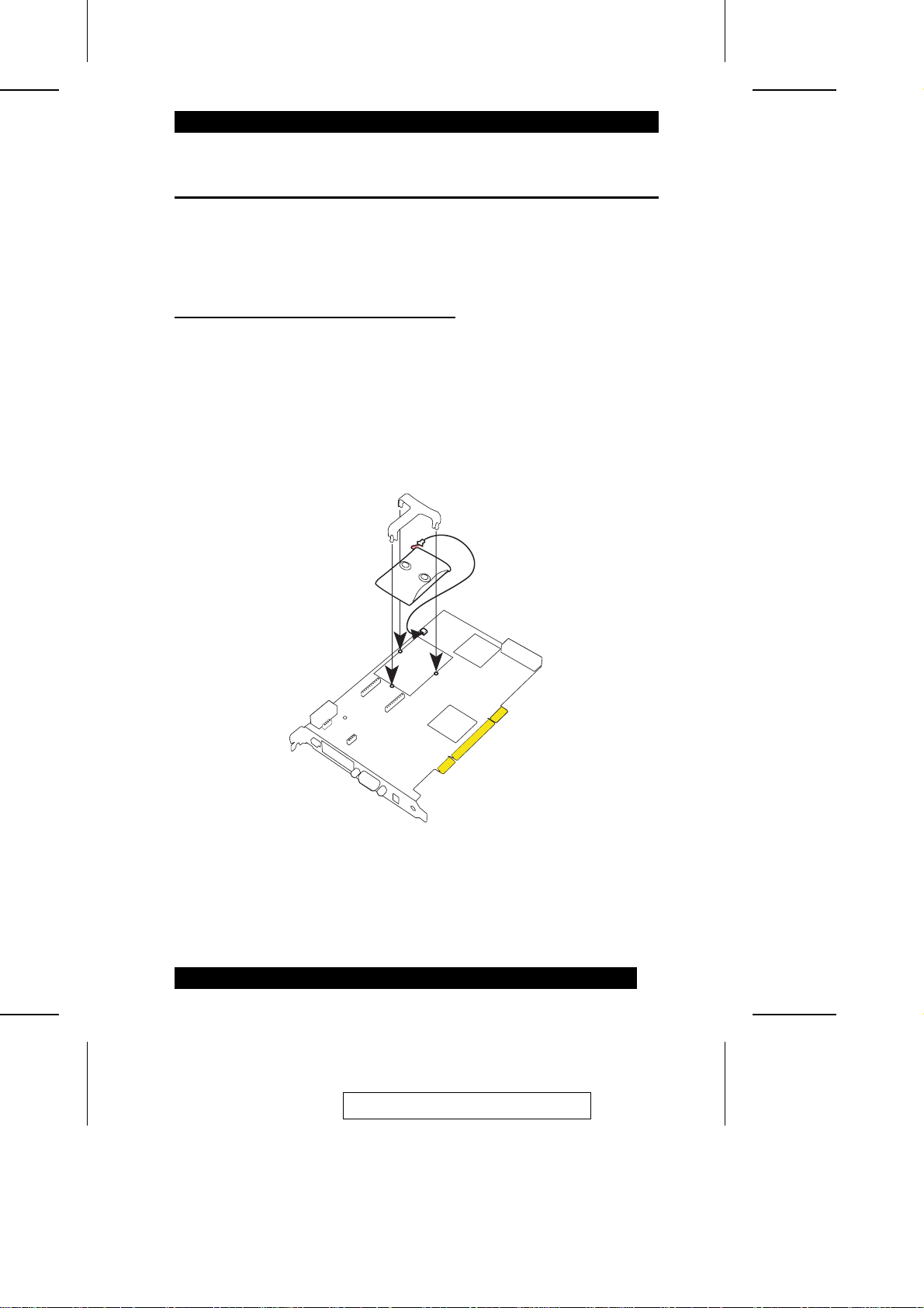
BBU (Battery Backup Unit) Installation
To install the Batte ry Ba c kup Unit, refer to the diagram below and do the following:
1. Plug the battery cable into the Battery connector (J2).
2. Place the battery pack in between the three mounting holes.
3. Align and snap the plastic battery clip into the t hre e m ount i ng holes over the
battery pack.
2005-06-09
11
Page 22

Charging the Battery Pack
Warning: Risk of explosion if battery type use d i s i nc orrect. ONLY use
battery part number BAT-LIION-3.6-01.
The optional battery pack is shipped uncharge d. The IP9001 card automatically starts
to charge the battery after you instal l i t . You m ust charge the battery pack before it
can be used to provide backup power to the IP9001 card. The minimum time that the
battery must be charged is six hours. To orde r extra batteries, contact your dealer.
Part No. Description Weight
BAT-LIION-3.6-01
Battery, Li-Ion, 3.6 V, 855/900 mAh on-board
battery pack with mounting brackets
If you keep a stock of extra IP9001 batteries, st ore t he m at room temperature.
Note: 1. Li-Ion has no memory effect. L i t hi um-ion cells offer extended c yc l e l i fe
when cycled at low depth of discharge.
33 g
2. The recoverable capacity of cel l s stored for over one year at room
temperature and fully charged is 94%. The retained capa c i t y of t he se same
cells is 87%. This means the se l f-discharge rate for a fully charge d c e l l i s
approximately 150 mAh per year or 427 uAh per day. The self-discharge
rate for cells is non-linear. A part i a l l y cha rged cell has a self-discharge rat e
of about 80 uAh per day.
12
2005-06-09
Page 23

Changing the Battery Pack
The optional IP9001 battery pack must be replaced every 400 cyc l es. Ce lls re tain 80%
of their original capac i t y a fter 400 cycles. A cycle is defined as a full charge (4. 2V)
followed by a full discharge (2.8V). Ke ep i n m ind t ha t cycling or storing the cells at
elevated temperatures can reduce the cell capacity and cycle life. Cells discharged and
stored at low temperatures can extend the shelf life of the batteries.
To replace the battery pack:
1. Bring down the operating system properly. Turn the computer power off. Remove
the computer cover. Remove the IP9001 card.
2. Disconnect the battery pack cable from jumper J2. Remove the plastic battery clip
and then replace the Battery Backup Unit.
3. Install a new battery pack and connect the new battery pa ck t o j um pe r J2. Al i gn
and snap the plastic battery clip int o t he t hree mounting holes over the battery
pack.
4. Reinstall the IP9001 card in the host system.
Battery Disposal
Warning: Do not dispose of the IP9001 optional battery pack by fire. Do not
mutilate the battery pack. Do not damage it in any way. Toxic chemicals can
be released if it is damaged. Do not short-circuit the battery pack.
The material in the battery pack contains heavy metals that can contaminate the
environment. Many jurisdictions have laws that prohi bi t the disposal of some
rechargeable batteries in public l a ndfills. These batteries must be sent to a specific
location for proper disposal.
You must comply with all applicable battery disposal and hazardous material
handling laws and regulations in the country or other jurisdiction where you are using
an optional battery pack on the IP9001 card.
13
2005-06-09
Page 24

3. Install the Optional Modem Daughterboard
The IP9001 modem daughterboard is an optional component. Loc a te JP10 on the
IP9001 card. It has a series of pinholes that all ow you t o insert the modem
daughterboard. Match the modem daughterboard and the pin holes so that the pi ns
align properly. Insert the modem daughterboard by sliding it straight down i nt o t he
IP9001 card. See Appendix F: Modem Daughterboard for more informat i on.
Note: 1. The optional modem is NOT designed for Console Redirection. Although you
can still perform Console Redirection, it is debilitating and extremely slow.
4. Plug the IP9001 Card into the Host System and
Attach Internal Cables
Plug the IP9001 into any available PCI slot on the host system and attach the inte rna l
cables as described in the following sections.
J3 - Service Connector
This jumper is used exclusively to service the IP9001 card. J3 is not described in this
document.
J4 - JTAG ICE Connector
The JTAG (Joint Test Action Group ICE (In-Circui t Em ulator) header is used to
debug and service the IP9001 card. J4 is not described in this document.
14
2005-06-09
Page 25

J5 - IPMB (Intelligent Platform Management Bus)
If your motherboard has an IPMB connector, you can connect a cable from J5 on t he
IP9001 card to the IPMB connector on your motherboard. The pin desc ri ption is
shown in the table below:
Pin Description
1
2
3
Positive Signal
Ground
Negative Signal
IPMB (Intelligent Platform Management Bus)
The IPMI specification was de veloped by Intel, Dell, Hewlett-Packard, and NEC to
provide a standard interface to be used for monitoring server items such as
temperature, voltage, fans, power supplies, and cha ssi s. IPMI is com prised of three
specifications Intelligent Platform Management Interface (IPMI), Intelligent Platform
Management Bus (IPMB) and Intelligent Chassis Management Bus (ICMB). The
IPMI specification defines the interface between management software and chassis
management hardware. The IPMB specification defines the internal Intelligent
Platform Management Bus. The ICMB spe ci fi cat i on defines an external bus for
connecting additional IPMI enabled systems.
The electrical interconnect for system management is base d on the inter-IC (I2C) bus.
This bus is a two wire serial interface (clock, data) dri ve n by open-collector drivers.
Devices arbitrate for the bus based on a colli si on de t ect i on m echa ni sm. The I2C data
and I2C clock signals are referred to as an IPMB.
The IPMB connector can be used to read IPMI information from the motherboard’s
System Management Controller. The format and de fi ni tion of the IPMI information
must be based on the IPMI v1.5 Specification.
The IPMI specification was architected around the server motherboard environment.
In a typical motherboard, the Manage m e nt Controller connects to a variety of dumb
sensors located on the motherboard and wi t hi n t he chassis. The command set contains
commands tailored to this environment and are intended to ha ndl e sensors, data
repositories, event logs and watchdog timers.
2005-06-09
15
Page 26

J9 - IP9001 Feature Connector
This feature connector is primarily used for operating the host system’s motherboard
power and reset switch. It can also be used t o ga t he r I2C bus inform at i on from t he
motherboard.. The pin descript i on i s shown i n t he t a ble below:
Pin Description Pin Description
1
Not Connected
2
I2C Clock
3
Not Connected
4
Not Connected
5
Power_Off #
6
I2C Data
7
Not Connected
8
Not Connected
9
Not Connected
10
Not Connected
Note: 1. JP13 and JP14 can be used in place of the IP9001 Feature Cable to gather
I2C bus information from the motherboard.
11
12
13
14
15
16
17
18
19
20
Reset_Host #
Ground
Ground
Not Connected
Not Connected
Ground
Not Connected
Not Connected
Not Connected
Ground
2. JP4 and JP5 can be used in place of the IP9001 Feature Cable to power on,
power off, and power cycle the motherboard.
3. JP7 and JP8 can be used in place of the IP9001 Feature Cable to reset the
motherboard.
4. Only the OEM version can utilize the hardware health monitoring
capabilities of IP9001 card. The hardware health monitoring function
requires an OEM specific cable and Sensor Defi ni tion Ki t (SDK/ SDR) fi le,
and Soft Processor (SP) file.
5. IPMI support is an OEM version feature.
6. This cable must be custom made for your specific configuration.
16
2005-06-09
Page 27

JP2 - Serial Port Connector
You can connect an external 9 pin serial port connector t o thi s he ade r. Thi s he ade r i s
primarily used to text redirect over the serial port.
JP3 - Service Connector
This jumper is used exclusively for servi ci ng the IP9001 card. JP3 i s not described in
this document.
JP4 and JP5 - Chassis/Motherboard Power Switch
JP4 and JP5 can be used in place of the IP9001 Feature Cable to power on, power off,
and power cycle the motherboard.
Connect a two pin cable from the motherboard’s Power (Soft On/Off) he ade r to JP4
on your IP9001 card. Connect the chassis power switch to JP5 on your IP9001 card.
JP6 - IP9001 Reset Button
You can short this jumper to reset your IP9001 card.
Pin Description
1
2
Ground
Reset #
JP7 and JP8 - Chassis/Motherboard Reset Switch
JP7 and JP8 can be used in place of the IP9001 Feature Cable to reset the
motherboard.
Connect a two pin cable from the motherboard’s reset heade r to JP7 on your IP9001
card. Connect the chassis reset switch to JP8 on your IP9001 card.
Note: JP7 and JP8 can be used instead of the IP9001 Feature Cable to reset the
motherboard.
2005-06-09
17
Page 28

5. Connect External Cables
1. Connect the USB cable from the back of the IP9001 card to the motherboard’s
USB port.
2. Connect your VGA monitor to your IP9001 card.
3. Connect the RJ45 LAN cable from your local network to your IP9001 card.
4. Connect your phone cord from the back of the IP9001 card to the telephone wall
outlet. (Only if the optional modem daughterboard is installed.)
5. Connect your AC adapter.
6. Confirm the Motherboard’s BIOS Settings
1. Power on the motherboard and enter the BIOS.
2. Use the following table to confirm that your motherboard’s BIOS settings are
correct.
BIOS Section Setting
Boot Options> Removable Devices Virtual Floppy or USB Boot Device
Boot Options> ATAPI CDROM Virtual CDROM or USB Boot Device
Advanced> PCIPnP>
Configuration> Legacy USB Support
Enable
3. Save the BIOS settings and restart the computer.
Note: 1. Make sure that your motherboard BIOS supports Legacy USB de vi ces,
USB Boot or Boot to USB.
2. On some motherboards and server boards, depress the <CTRL>, <ALT>,
and <ESC> keys simultaneously to enter the BIOS. On ot he rs use the <F2>
keys. See your server’s documentation for m ore information on entering
the BIOS setup.
18
2005-06-09
Page 29

7. Install the Operating System and IP9001 Drivers
1. Install the operating system (if applicable) on the host system.
2. (Windows 2000/2003/XP only) When prompted for the Virtual Fl oppy dri vers,
install the IP9001 card’s Virtual Floppy dri ve rs l oc a te d i n t he INF folder on the
IP9001 CD.
3. (Windows 2000/2003/XP only) When prompted for the virtual CD-ROM drivers,
install the Windows default CD-ROM drivers.
Note: Do not use virtfl.inf when prompted to install the virtual CD-ROM
drivers. The Virtual CD-ROM device does not require any special drivers.
You can select the default option Microsoft Windows provides.
Installing Virtual Floppy Drivers on Microsoft® Windows
Microsoft® Windows 2000/2003/XP operating systems need an .INF file to ha ndl e
Virtual Floppy device provided by the IP9001 card.
Note: The .INF installation procedure only needs to be done once on the host
system. Once the Virtual Floppy is properly loaded, you can perform floppy
redirection without going through any extra st eps.
2005-06-09
19
Page 30
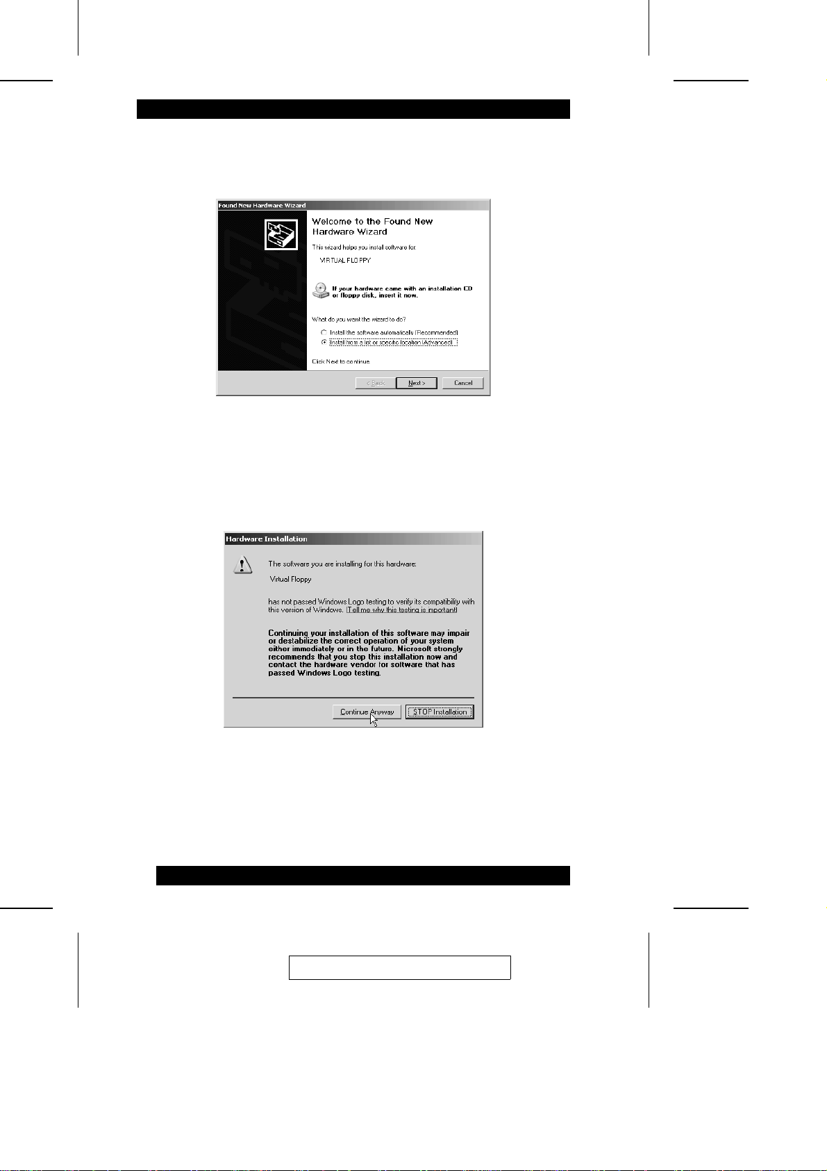
The first time you run windows after installing the card, the Found New Hardware
Wizard comes up:
1. Select Install from a specific location, then click Next.
2. Select the virtfl.inf file, located in the INF directory on the IP9001 CD. If
prompted with the Windows Logo dialog box, cl ick Continue Anyway.
Note: Do NOT use the default file that the Microsoft® Windows operating system
presents when it is searching for the Virtual Floppy driver. Ensure that the
Microsoft® Windows operating system is asking for the the virtual floppy driver on
the IP9001 CD before allowing the installation of the .INF file to continue.
20
2005-06-09
Page 31
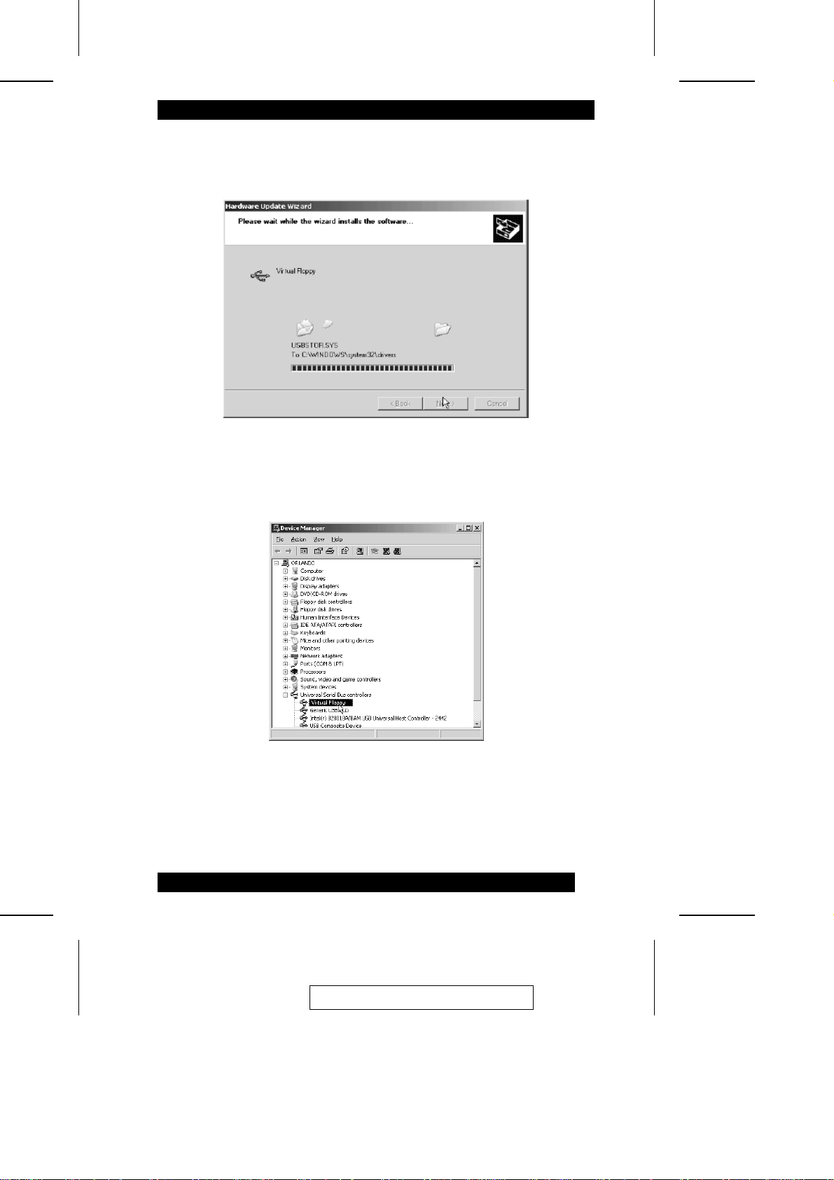
As the Hardware Update Wizard loads the virtual floppy drive r from the IP9001
CD, the installation progress status is di spl aye d.
3. Once the file is loaded, click Finish to complete the installation. (Windows may
require a reboot of the host system after the installation of the virtual floppy driver.)
4. Check in the Device Manager to be sure the driver was properly inst alled.
2005-06-09
21
Page 32

8. Install the Windows Software Components
The Windows Software Components comprise a collection of host-side and re mote
access programs. Their functions are briefly explained in the followi ng tabl e:
Program Description
ConfigApp Allows you to configure the IP9001 card either from the host
WinCuri A command prompt-based program to configure the IP9001
HostHeartbeat HostHeartbeat is installed as a service in Windows. It tells
Floppy Image
Creator
Remote Recovery
Application (RRA)
RacTrendsSeek
Locator
(RM Seek)
system or from a client system.
card. It allows you all the functionality of both the Internet
browser-based Remote Access Companion for the IP9001,
and the ConfigApp program.
whether or not the operating system on the host system is
functioning. It can also detect whether the operating system
was shutdown normally or not.
Used to create bootable floppy image files that you can use
to boot the IP9001 card from.
A recovery tool that can be executed from a remote client
system located on the same network as the IP9001 card.
You can use it to recover a failed flash attempt.
Note: 1. You must physically set the IP9001 card you want
to recover into Recovery Mode by shorting pins 2
and 3 of jumper JP12.
2. The IP9001 card must be write enabled before you
can flash an image to it. Shorting pins 1 and 2 on
jumper JP11 write enables the card.
3. Since the firmware upgrade process is a critical
operation, make sure that the chances of a power or
connectivity loss are minimal when performing this
operation.
In order to completely configure your IP9001 card, you must
access it from another system on the same network by
means of its IP address. If you have installed the IP9001 on
a network that uses DHCP, you can search the network for
the IP9001 card. To locate and find out its IP address, you
can use RacTrendsSeek Locator.
22
2005-06-09
Page 33
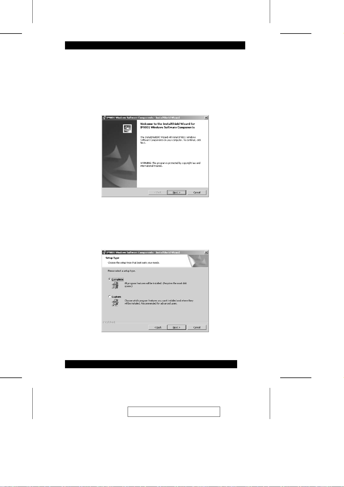
To install the Windows Software Components, do the following:
1. Insert the IP9001 CD into the host system (the one with the IP9001 card); and
navigate to the CDROM\ServerAgents\Win32 folder; and double click Setup.exe.
The Installshield Wizard comes up.
2. When the confirmation window comes up, click Next, to move on:
3. If the Customer Information dialog box comes up, enter your name and t he na m e
of your organization in the appropriate fields.
4. When the Setup Type window opens, select Complete, then click Next:
2005-06-09
23
Page 34
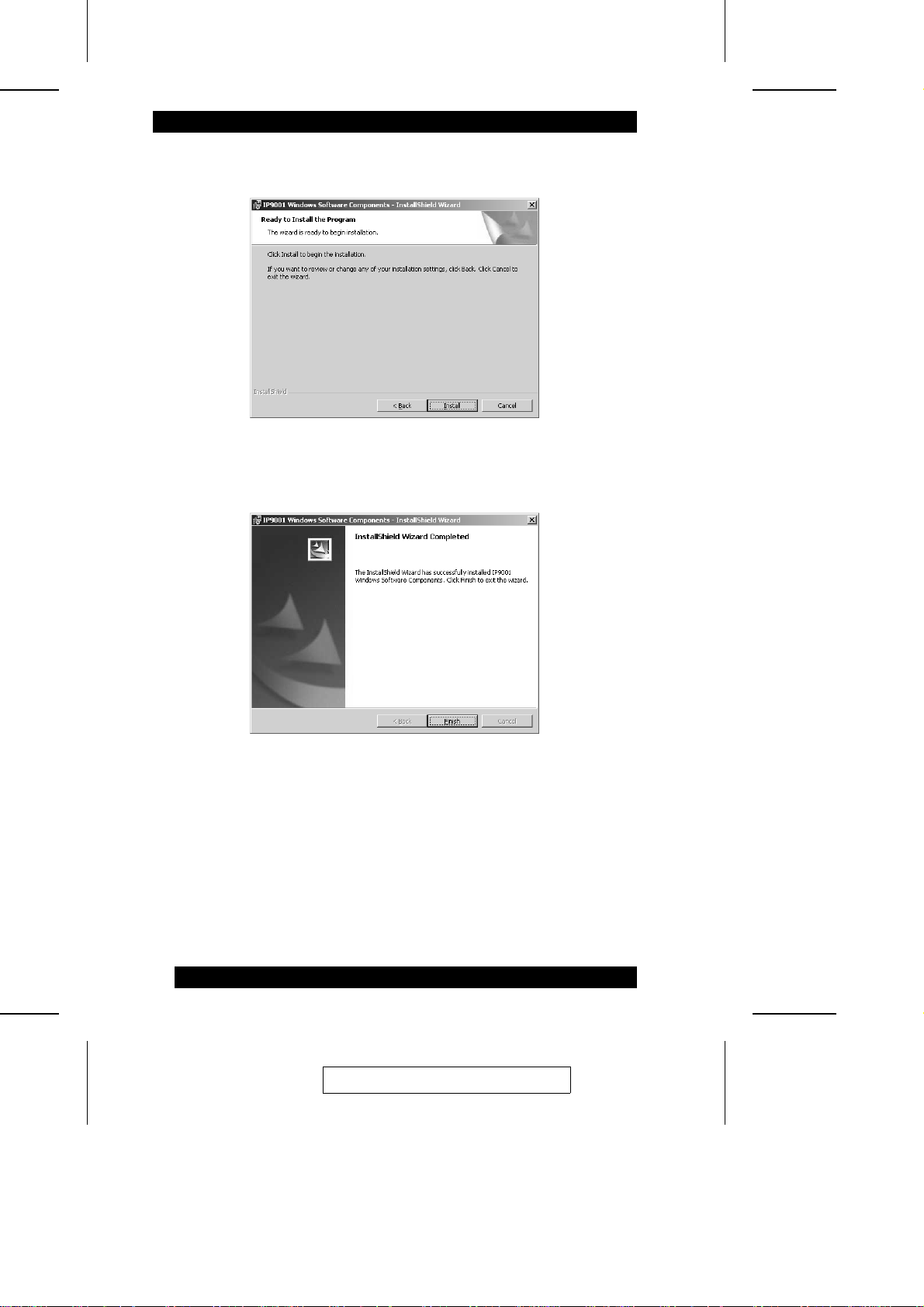
5. When the Install Program window opens, click Install:
6. When the installation is complete, click Finish to complete the procedure:
7. Repeat steps 1 - 6 for any local network computers you wish to use to access the
host system.
24
2005-06-09
Page 35
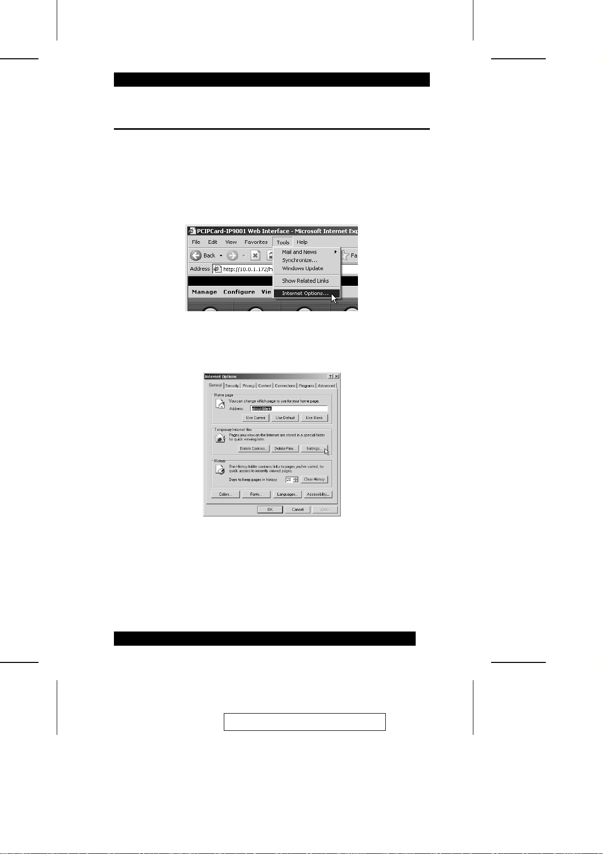
9. Setup Your Client Internet Browser
Before you can redirect the host system’s console or view the Crash screen, you must
first set up your Internet browser on the client system. To do so, follow the steps,
below:
1. Open your Internet Explorer browser. From the menu, select Tools, then select
Internet Options:
2. When the Intenet Options window opens, click Settings:
2005-06-09
25
Page 36
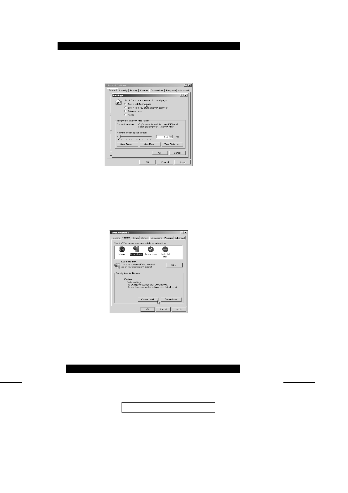
3. In the Settings window, select Every visit to the page or Automatically; then click
OK to apply the change and to go back to the Internet Options dialog box:
Note: Other settings can cause old data to be displayed when performing
operations on the IP9001.
4. To setup Internet Explorer to allow downloading and running of signed ActiveX
controls, in the Internet Options dia l og box, select the Security tab; then click
Custom Level:
Note: The default security setting for Microsoft Windows 2003 servers i s High.
This disables many components necessary for t he IP9001 GUI. The re fore ,
you should set the security settings for a remote client running Windows
2003 server to Medium, or Low.
26
2005-06-09
Page 37
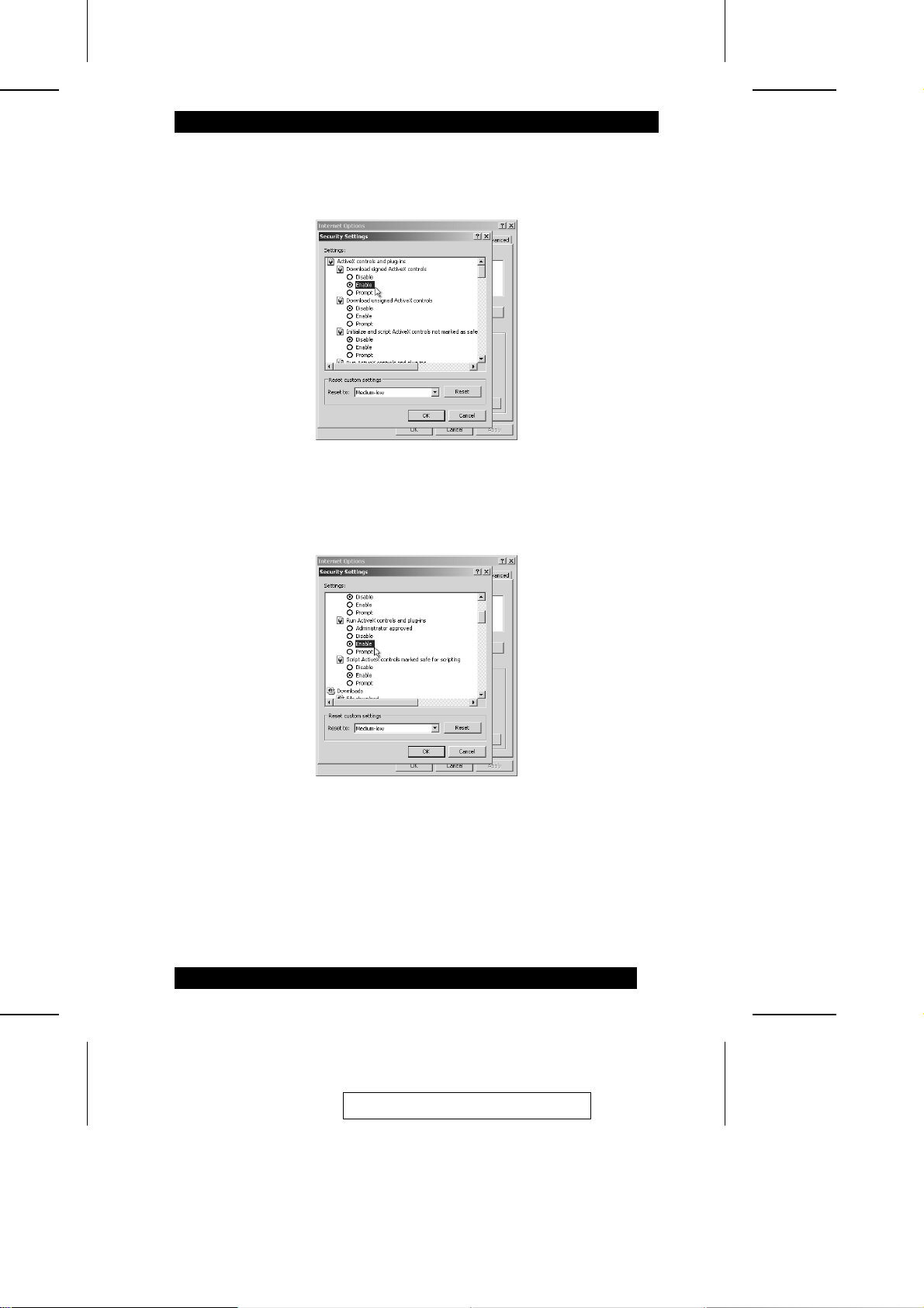
5. In the Security Settings dialog box, in the Download signed ActiveX controls
section select Enable:
6. Scroll down to the Run ActiveX controls and plug-ins section. Select Enable; then
click OK:
2005-06-09
27
Page 38
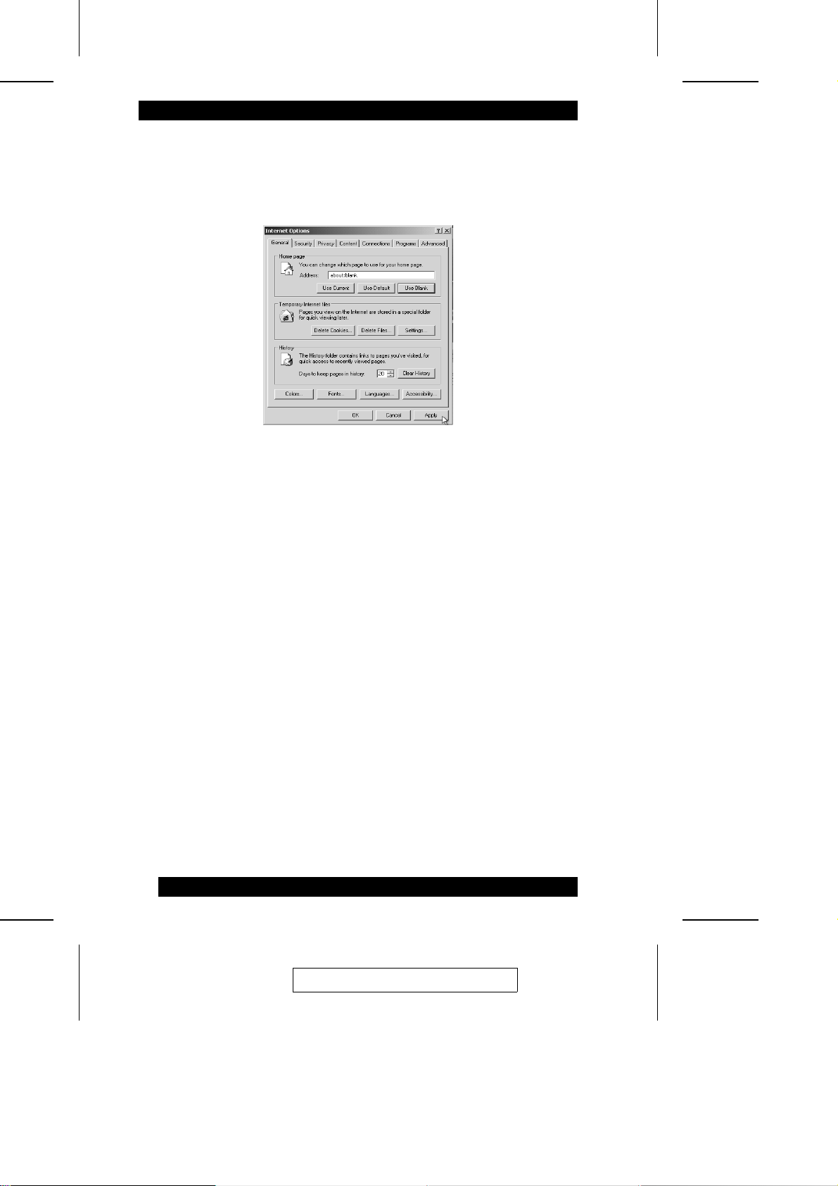
7. When the Warning! dialog box comes up, click Yes to accept the changes and go
back to the Internet Options dialog.
8. Click Apply, then click OK to complete the changes:
Note: 1. You must restart Internet Explorer before the changes take effect.
2. Remote Console cannot run with any other security settings in Internet
Explorer.
28
2005-06-09
Page 39

10. Connecting From a Client System
In order to connect to the IP9001 card, you must access the IP9001 from another
system on the same network (referred to in this manual as the client system). T o do
this, you must know the IP9001 card’s IP address. If you have inst al l ed t he card on a
network that uses DHCP, you can search the network for the IP9001 card. To loca te
and find out its IP address, you must run RacTrendsSeek Locator.
Note: 1. To get or set the IP address on the IP9001 card in a Windows
2003/2000/XP environment, you can also run the ConfigApp program on
the host system. See Appendix B, ConfigApp for more i nform at i on on how
to use this program.
2. Make sure that you have already installed the IP9001 Windows Sof tware
Components on the system that you want to use to locate the IP9001 card.
To connect to the IP9001 from a remote client system, do the following:
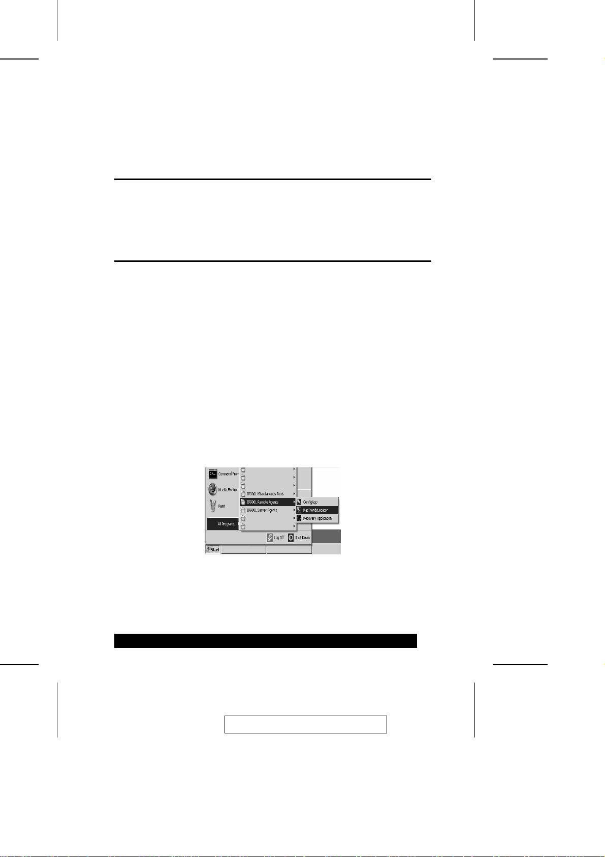
1. Run the RacTrendsSeek Locator program entry on your remote client system:
2005-06-09
29
Page 40
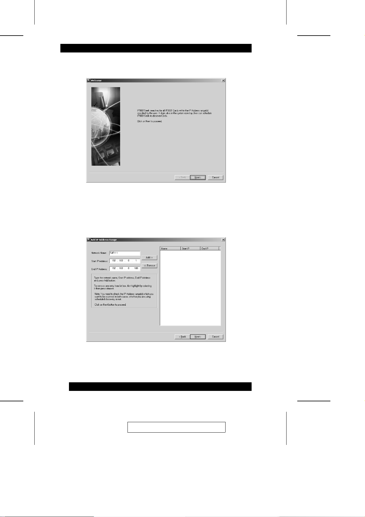
2. When the opening screen comes up, click Next:
3. When the Add IP Address Range dialog box comes up, key in a name for your
network in the Network Name field, and the range of IP addresses that the card’s
IP address will fall under, then cli c k Add:
30
2005-06-09
Page 41
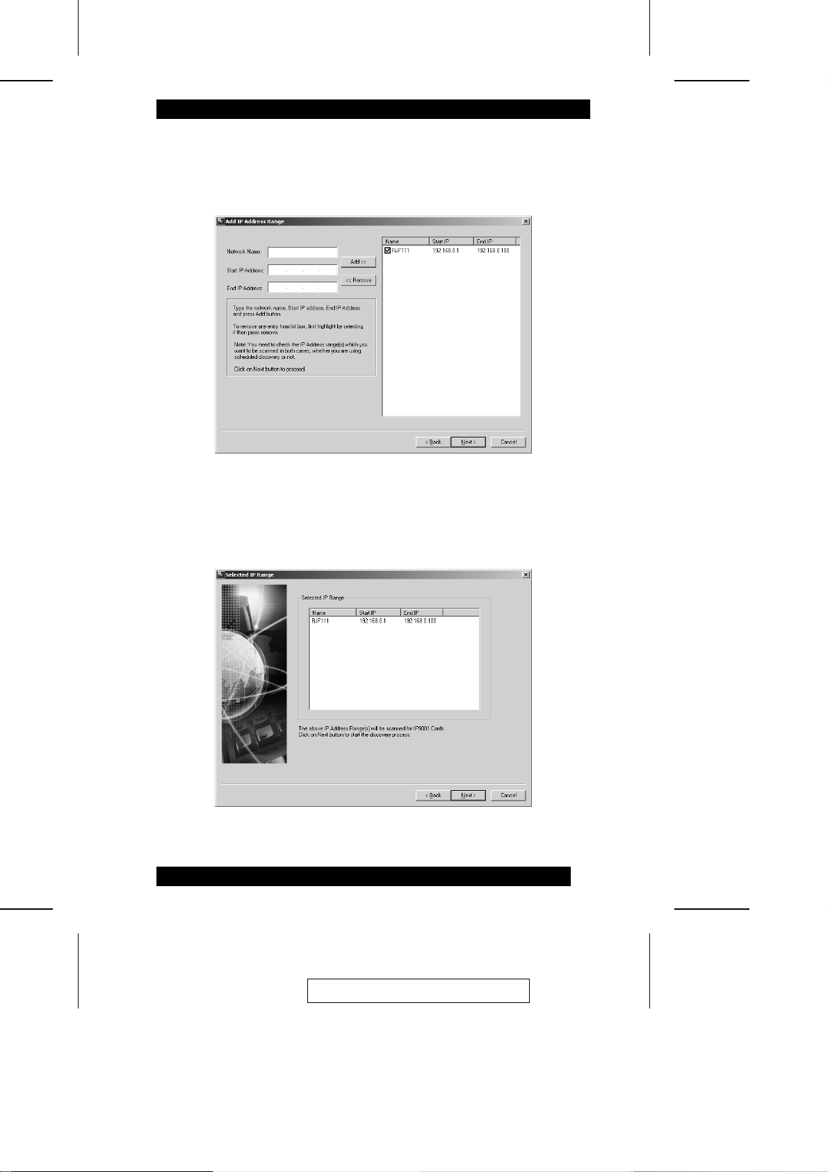
4. In the dialog that comes up, the name and IP range of the IP9001 card appears in
the list at the right. Place a check in the box next to the range of IP addresses, then
click Next:
5. The Selected IP Range dialog comes up with the name and IP range of the IP9001
card displayed. Click Next to continue:
2005-06-09
31
Page 42
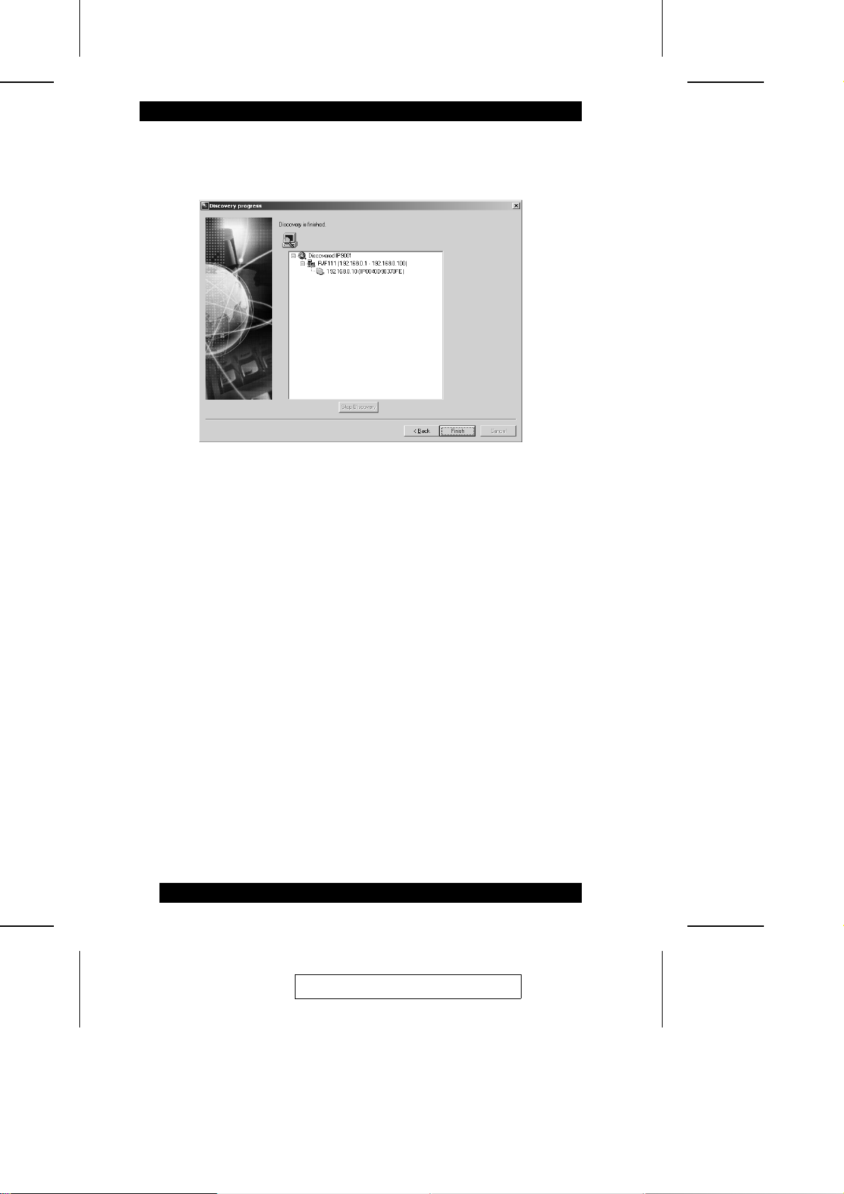
6. If the IP range is correct, RacTrendsSeek Locator will locate the IP9001 card, and
list it with all the IP9001 cards it has discovered:
Note: If more than one IP9001 card is found, you can distinguish them by the
IP9001 card’s name. The IP9001 card’s name consists of the characters IP
followed by the MAC address of the card’s NIC.
7. In this example, the IP9001 card’s IP address is 192.168.0.10. Double click the IP
address to start managing the IP9001 card and write down i t s IP addre ss. Aft er
RacTrendsSeek Locator discovers all the IP9001 cards, Click Finish.
32
2005-06-09
Page 43

8. The login screen comes up:
The default User Name is root; the default password is superuser (both in lower case).
Note: When you log in using this user name and password, you have full
administrative privelege ss. For security purposes, we strongly advise you
to change the root password. See Administrator Setup unde r t he IP9001
Configurations section of this chapter.
2005-06-09
33
Page 44
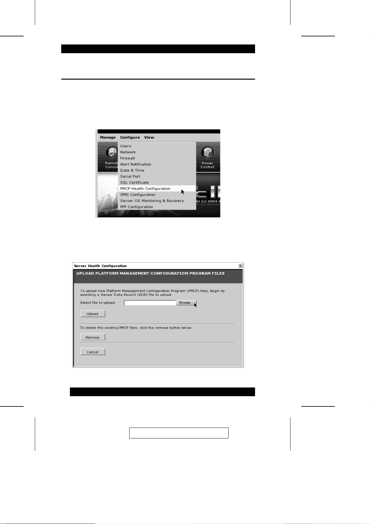
11. Load the SDR and Soft Processor (SP) File
This is an optional procedure and requires a custom file specific to your motherboard.
To load the SDR and Soft Processor (SP) file, do the following:
1. Select Configure from the menu bar at the top of the IP9001 GUI, then select
PMCP Health Configuration from the menu:
2. The Host Health Monitoring Files dialog box opens. Cli c k Browse:
34
2005-06-09
Page 45

3. Starting from the IP9001 CD, browse to the folder that contains your SDR file.
Note: You can create your own SDR and Soft Processor (SP) Files using the
Platform Management Configuration Program (PMCP).
4. Select the SDR file (it will end in -sdr.bin), then click Open:
5. In the dialog box that comes up, click Upload:
6. The next dialog box confirms that the the SDR file was successfully uploaded, and
prompts you to upload a Soft Processor Instruction Set file. Click Browse to continue.
7. In the dialog that comes up, select the SP file (it will end in -sp.bin), then click
Open:
8. In the dialog box that comes up, click Upload:
9. The next dialog box confirms that the the SP file was successfully uploaded, and Host
Health monitoring is active:
Click Close to end the install a t i on proc edure .
2005-06-09
35
Page 46

Notes:
36
2005-06-09
Page 47
Chapter 3.
Locating the IP9001 Card
Overview
IP9001 cards can be accessed from anywhere on your Intranet via an Int erne t
browser, allowing you to maintain your critical servers from a physically remote
location. This chapter explains how to loc at e t he IP9001 card on your l oca l ne t work.
Locating the IP9001 Card
In order to connect to the IP9001 card, you must access it from another system
(referred to as the client system) on the same ne twork. To do this, you must know the
IP9001 card’s IP address. If you have installed the IP9001 on a net work t ha t use s
DHCP, you can ascertain its IP address with the RacTrendsSeek Locat or program.
Note: 1. In a Windows 2000/XP environment, you can also get or set the IP9001’s IP
address by running the ConfigApp program on the host system. See Appendix
B, ConfigApp, for more information on how to use the program.
2. Make sure that you have already installed the IP9001 Windows Soft wa re
Components on the system that you want to use to locate the IP9001 card.
To connect to the IP9001 from a remote client system, do the following:
1. Run the RacTrendsSeek Locator program:
37
2005-06-09
Page 48
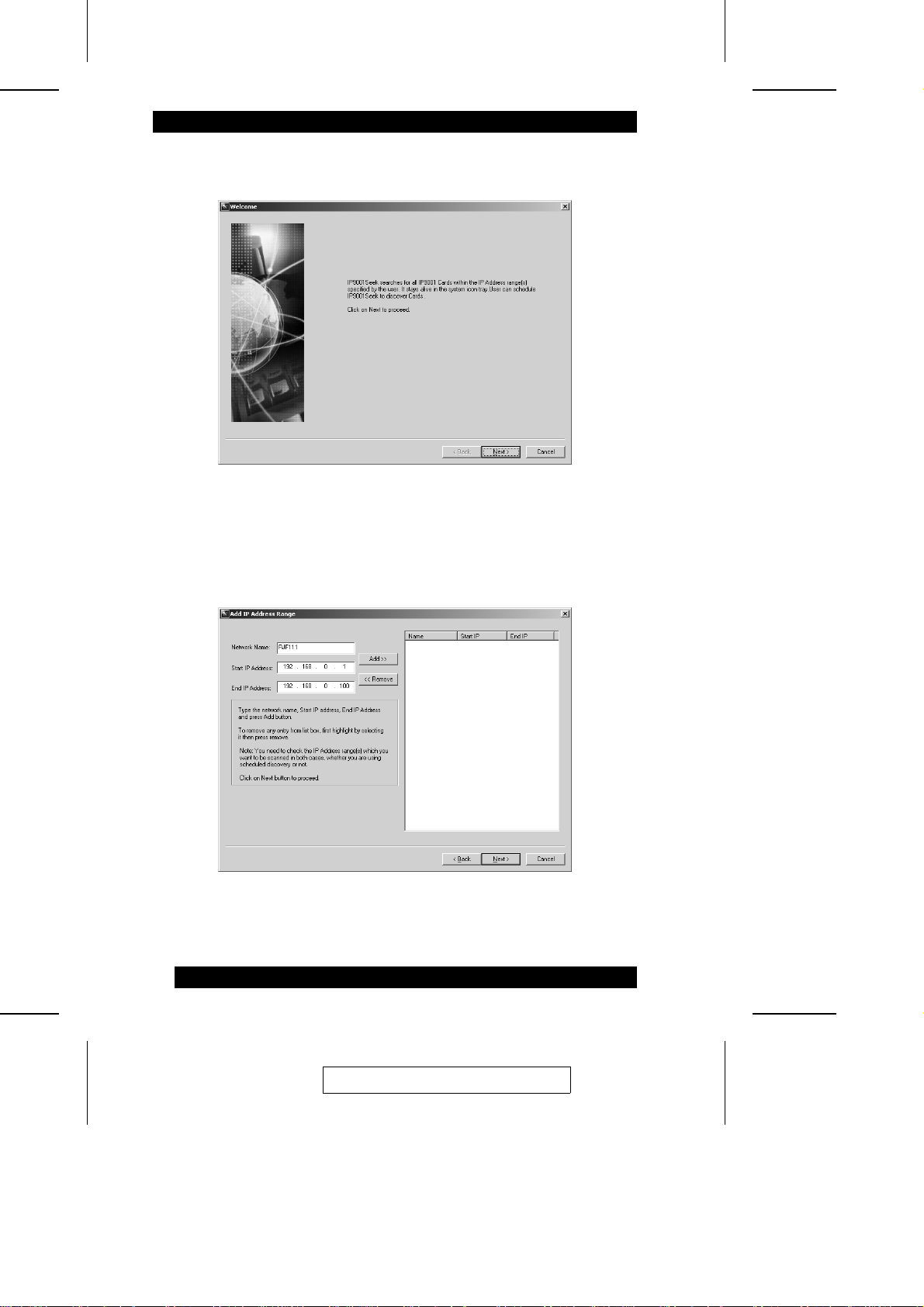
2. When the opening screen comes up, click Next:
3. When the Add IP Address Range dialog box comes up, key in a unique name for
your network in the Network Name field, the n ke y i n the ra nge of IP addresses that
the card’s IP address will fall under, in the St art IP Address and End IP address
fields, then click Add:
Note: If you only wish to scan for one card with a specific address, t he St a rt a nd
End addresses should be the same.
38
2005-06-09
Page 49
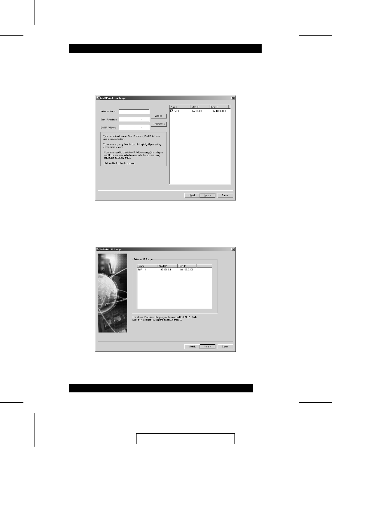
4. In the dialog that comes up, the name and IP range of the IP9001 card appears in
the list at the right. Place a check in the box next to the range of IP addresses, then
click Next:
5. The Selected IP Range dialog comes up with the name and IP range of the IP9001
card displayed. Click Next to continue:
2005-06-09
39
Page 50
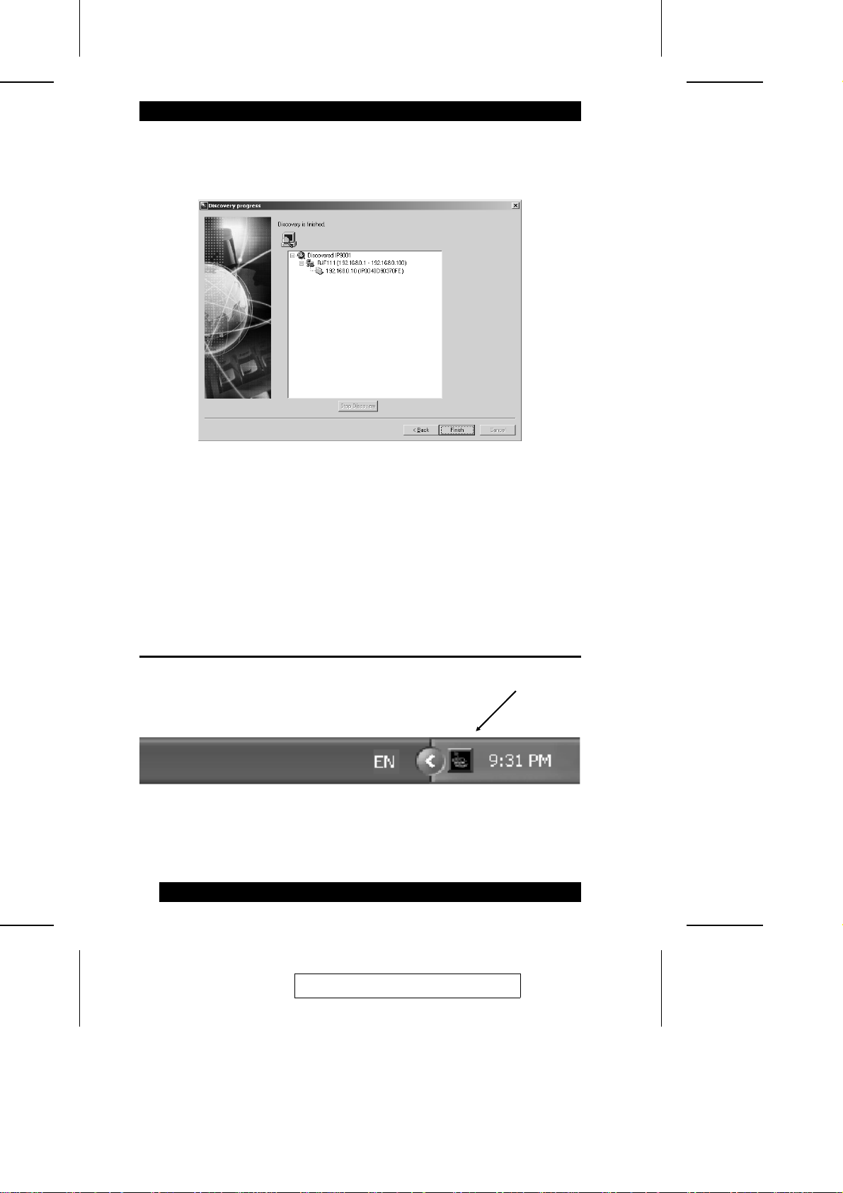
6. If the IP range is correct, RacTrendsSeek Locator will locate the IP9001 card, and
list it with all the IP9001 cards it has discovered:
Note: If more than one IP9001 card is found, you can distinguish them by the
IP9001 card’s name. The card’s name consists of the characters IP
followed by the MAC address of the card’s NIC.
7. In this example, the IP9001 card’s IP address is 192.168.0.10. Double click the IP
address to start managing the IP9001 card and write down i t s IP addre ss. Aft er
RacTrendsSeek Locator discovers all the IP9001 cards, Click Finish.
Usage
Once the program has been installed and setup, you can access it any time by double
clicking its icon on the task bar:
The screen that was active when the program was last viewed will appear.
40
2005-06-09
Page 51
Chapter 4.
Browser Operation
Overview
The IP9001’s user-friendly Graphics User Interface (GUI) is accessed wi th a st anda rd
Internet browser. Specify the IP9001’s IP address in your browser’s Loc a t or ba r, and
you can be up and running in a matter of minutes. Thi s cha pt e r de scribes the browser
screen layout, and explains how to use each of the IP9001’s features and functions.
Note: 1. If you don’t know the IP9001’s IP address, get it from your adm i nistrator.
2. Some elements of the GUI may have changed since this manual was
written. If the GUI on your monitor does not m a t c h t he ones in this
document, go to our website to download t he m ost current version.
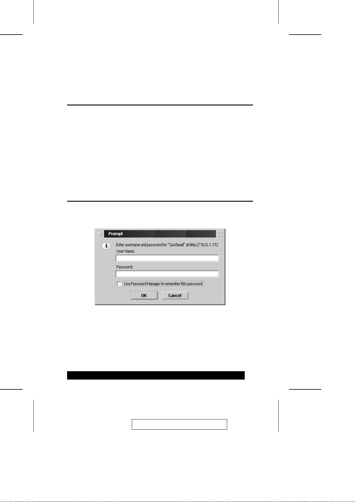
Logging In
Before you are granted access to the IP9001 web page, a logi n pa ge comes up asking
you to provide a User Name and Password:
Provide a valid Username and Password, then Click OK to continue .
Note: 1. If you are the administrator logging in for first time, use the default User
Name: root; and the default Password: superuser. Use lowe r c a se for both.
2. This login gives you full administrative powers. For security purposes, we
strongly recommend you change the root password to som ethi ng uni que.
2005-06-09
41
Page 52
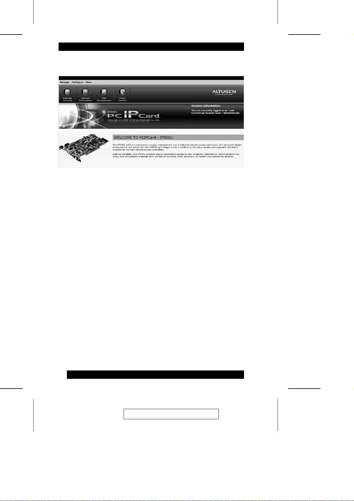
After you have successfully logged in, the IP9001 Main Screen appears:
M The Menu Bar at the top of the screen consists of three items:Manage, Configure ,
and View. Clicking a menu item causes a drop down l i st of submenu choices. The
meanings and use of these coices are explained in the chapte rs tha t fol low.
M Below the menu bar, are four Quick Launc h icons. The se icons are a short cut
method to access their equivalent functions found in the menu bar submenus.
M The Session Information entry at the right of the screen shows the Use r Na me and
permission level of the curre nt ly logged in user.
42
2005-06-09
Page 53
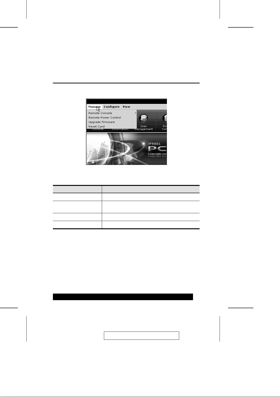
The Manage Menu
Overview
When you click Manage on the menu bar, its submenu drops down:
A brief description of the items is given in the table below:
Chapter 5.
Item Description
Remote Console Starts a remote console session with the host system.
Remote Power Control Powers On, Powers Off, Power Cycles or Resets the
host system.
Upgrade Firmware Upgrades the IP9001’s firmware.
Reset Card Resets the IP9001 card.
Each entry is explained in detail in the sections that follow
43
2005-06-09
Page 54

Remote Console
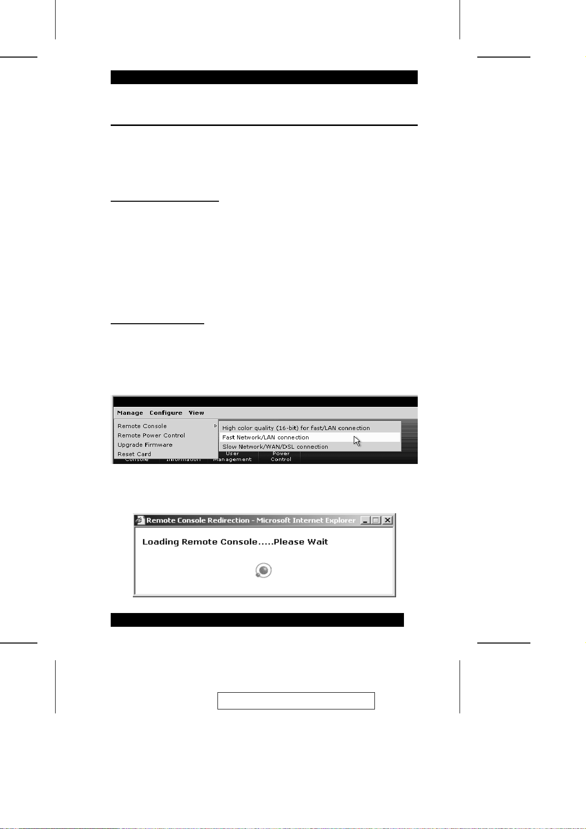
The Remote Console submenu offers three choices for remote consol e di splay as
shown in the figure and table below:
Item Description
High Color Quality (16-bit)
for fast/LAN Connection
Fast Network/LAN
connection
(Low Color Quality)
Slow Network/WAN/DSL
Connection
(Low Color Quality)
Allows the IP9001 to send 16 bits per pixel color.
Recommended for faster connection speeds or over a
LAN connection.
Allows the IP9001 to send 8 bits per pixel color.
Recommended for lower connection speeds or over a
WAN connection.
When using this connection, you can opt not to use
software compression. Compression can increase the
frame rates. It is best used for slower connections.
Allows the IP9001 to send 8 bits per pixel color.
Recommended for lower connection speeds or over a
WAN connection.
When using this connection, you can also use software
compression. Compression can increase the frame rates.
It is best used for slower connections, such as DSL.
Note: The Low Color Quality (8-bit) for slow/WAN/DSL Connection mode is
recommended for low speed connections such as t hose ove r a Wi de Area
Network or home DSL. If you are connecting over a LAN at high spe eds you
can use High Color Quality (16-bit) for fast/LAN Connection mode. In order
to change modes you must stop redirect i on, close the browser, and reconnect
in the appropriate mode.
44
2005-06-09
Page 55
Console Redirection
The most powerful feature of the IP9001 is the ability to redirect the host system’s
console - giving you the ability to manage your host system as if you were actually
right in front of it.
Internet Explorer Setup
Before you can perform redirecti on, you must first set up Internet E xpl orer. This is
the same procedure that was described in Chapter 2, pages 25 to 28. If you haven’t
already set IE up according to the steps descri bed, refer back to that sect i on t o se t up
your browser now.
Note: The Remote Console program cannot run, and console redirection cannot take
place, unless Internet Explore is set up according to the steps indicated.
Starting Redirection
To begin Console Redirection, do the following:
1. From the Manage menu, select Remote Console, then the quality mode you wish
to use:
The Loading Remote Console screen appears:
2005-06-09
45
Page 56
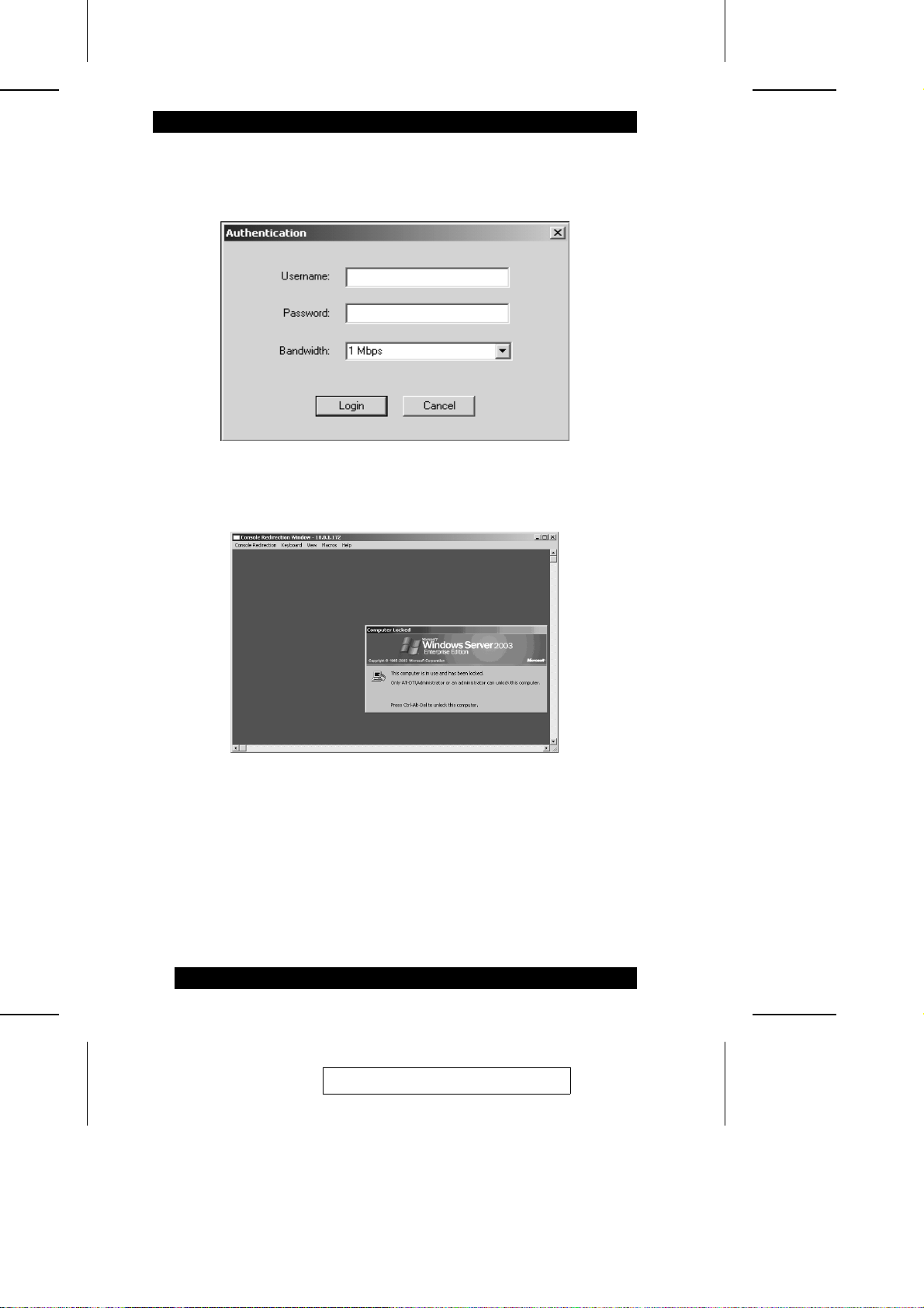
2. When the authentication dialog box comes up, key in your Username and
Password; select a data transmission speed; then click Login:
The Console Redirection screen opens:
Now that you have redirected the host system’s console, you have the ability to
manage the host system from your console just as if you were physically at it.
3. Drop down the Keyboard menu, and click the Alt+Ctrl+Del entry to begin.
The next sections explain how to use the console redirection screen.
46
2005-06-09
Page 57
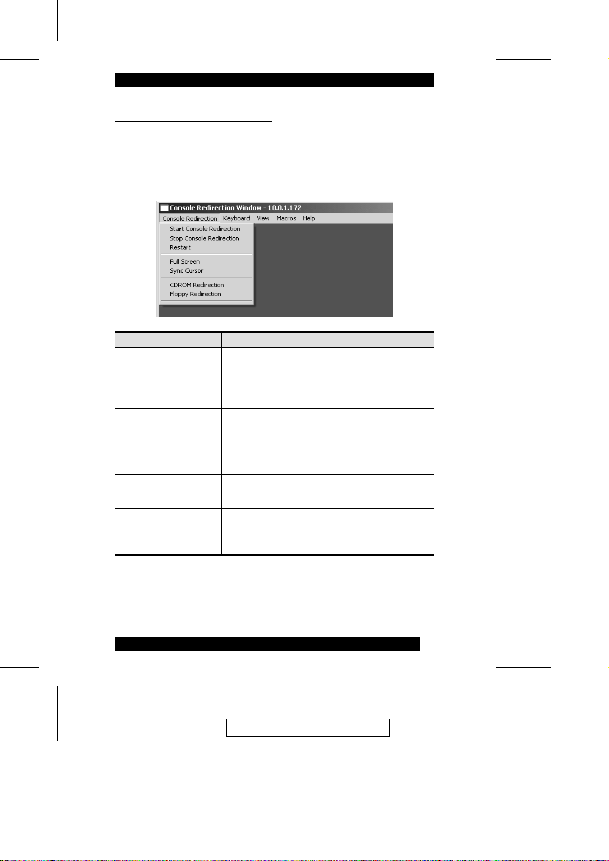
The Console Redirection Screen
Several drop down menus to manage the host system are arranged across the screen.
The next sections describe the functions of each of the menu items.
The Console Redirection menu:
Item Function
Start Console Redirection Begins console redirection
Stop Console Redirection Ends console redirection
Restart When console redirection is active, it stops redirection,
Full Screen Toggles viewing console redirection in Full Screen
then restarts it.
mode On or Off.
Note: Set the client system screen resolution to 1024 x
768 in order to view the host system in true full screen
mode.
Sync Cursor Syncs or unsyncs the host and client mouse pointers.
CDROM Redirection Toggles the redirection of the CDROM drive On or Off.
Floppy Redirection Toggles the redirection of the floppy drive On or Off.
Note: This feature is not available on all versions of the
IP9001.
Note: These functions can also be performed with hotkey combinations. Se e p. 71
for details.
2005-06-09
47
Page 58
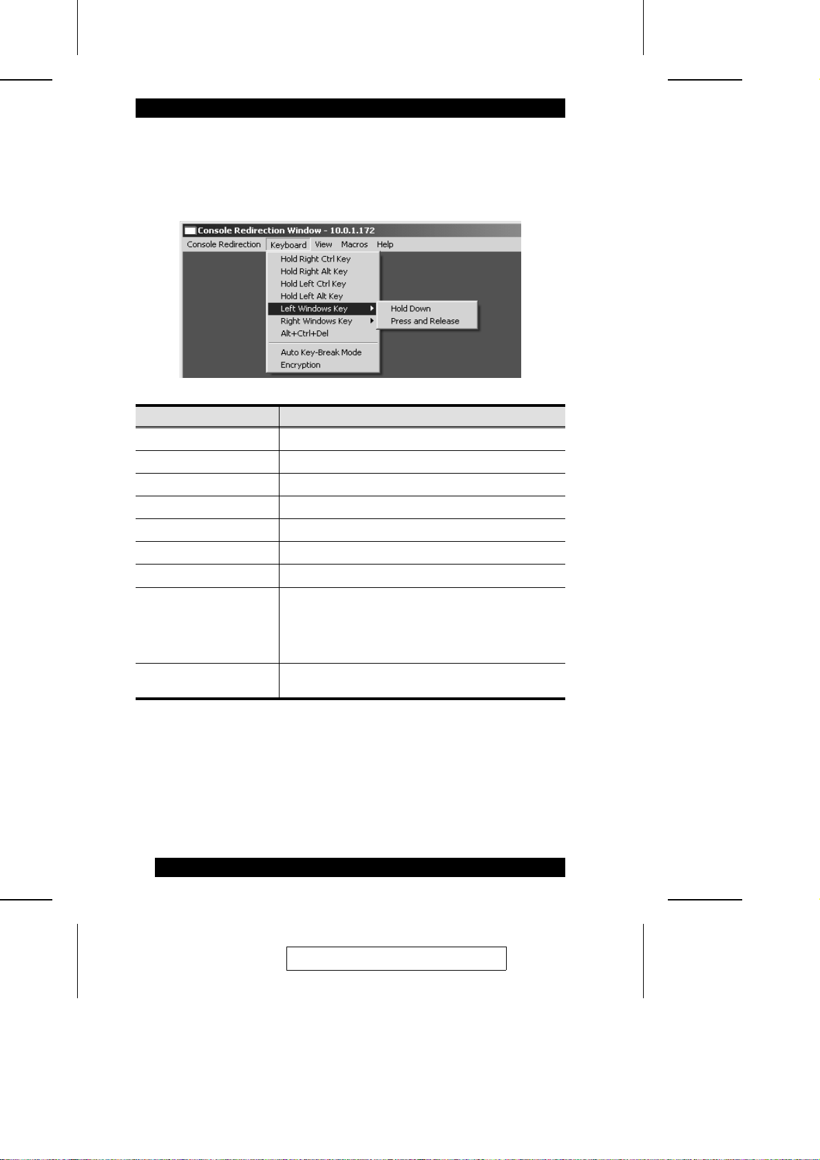
The Keyboard Menu:
Under console redirection some keystrokes cannot be captured and sent to the host
system - the items on this menu provide the keystroke functionality to the host system.
Item Function
Hold Right Ctrl Key Acts as the Right Ctrl key*
Hold Right Alt Key Acts as the Right Alt key*
Hold Left Ctrl Key Acts as the Left Ctrl key*
Hold Left Alt Key Acts as the Left Alt key*
Left Windows Key Acts as the Left Windows key
Right Windows Key Acts as the Right Windows key
Alt+Ctrl+Del Acts as the Ctrl-Alt-Del combination*
Auto Key-Break Mode This menu item must be enabled when USB keyboard
Encryption Click this item to enable/disable encryption of the
emulation is used. The IP9001 does not use USB
keyboard emulation. Instead, the IP9001 uses legacy
PS/2 emulation. This feature is used to avoid repeated
keystrokes over slow connections.
keyboard data being transferred from the remote client.
* This function can also be performed with a hotkey combinations. Se e p. 71 for
details.
48
2005-06-09
Page 59
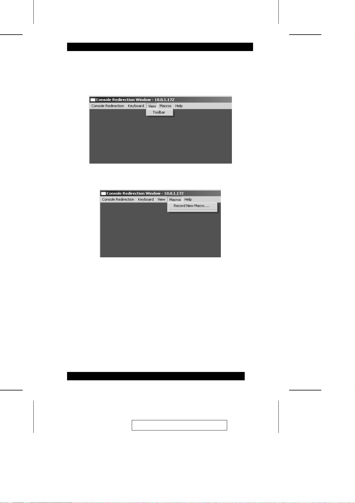
The View Menu:
This View menu contains one item: Toolbar. Clicking Toolbar brings up the Console
Redirection toobar. The Console Redi re ction tool ba r is discussed in detail on p. 50.
The Macros Menu:
Record New Macro allows you to record a set of keystrokes. A good exa m pl e of how
this would be useful is when the IP9001 is used in conjunction with a KVM swi tch.
Normally, you must use a key sequence to switch systems. With a pre-recorded macro
created for that purpose, you could switch systems by runnning the macro inst ead of
having to input the sequence ma nua lly.
The Help Menu:
This menu contains the About RConsoleOCX Control item. Click it to view the
RConsoleOCX Control version number and copyright information.
2005-06-09
49
Page 60
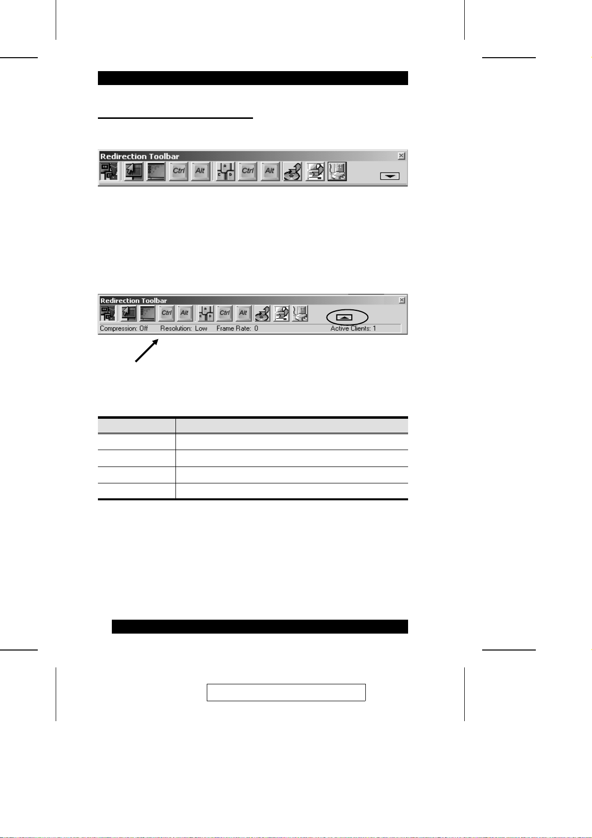
The Console Redirection Toolbar
Clicking Toolbar on the View menu brings up the Consol e Redirection toolbar:
The toolbar allows you to perform console redi re ct i on functions more conveniently
when you are in full screen mode and the m enus are not visible. It is especially useful
if you are not familiar with the hotkey combinations.
Clicking the arrow at the right of the toolbar displ ays Console Redirection Status
information:
The meanings of the fields are given in the table below:
Field Function
Compression Indicates whether or not you are using compression.
Resolution Indicates the resolution quality.
Frame Rate Indicates the current fram rate.
Active Clients Shows how many users are currently logged into the IP9001.
50
2005-06-09
Page 61
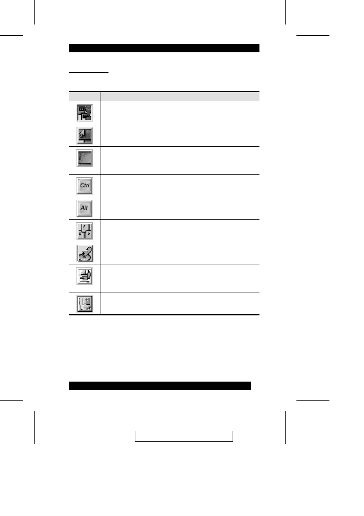
Toolbar Icons
The function that each of the toolbar icons performs is desc ri be d in the table below:
Icon Description
Toggles Console Redirection On and Off.
Toggles mouse synchronization On and Off.
Toggles full screen mode On and Off.
Note: Set your client’s resolution to 1024 x 768 to see the host system
in true full screen mode.
Toggles the Ctrl key On and Off. The icon on the left of the CAD
button represents the Left Ctrl key; the icon on the right of the CAD
button represents the Right Ctrl key.
Toggles the Alt key On and Off. The icon on the left of the CAD button
represents the Left Alt key; the icon on the right of the CAD button
represents the Right Alt key.
Performs a Ctrl+Alt+Del (CAD) operation.
Toggles CDROM device redirection On and Off.
Toggles floppy device redirection On and Off
Note: Floppy device redirection is not available on all versions of the
IP9001 card.
Toggles the Power Control dialog box On and Off. Remote power
control is discussed in detail on p. 63.
51
2005-06-09
Page 62
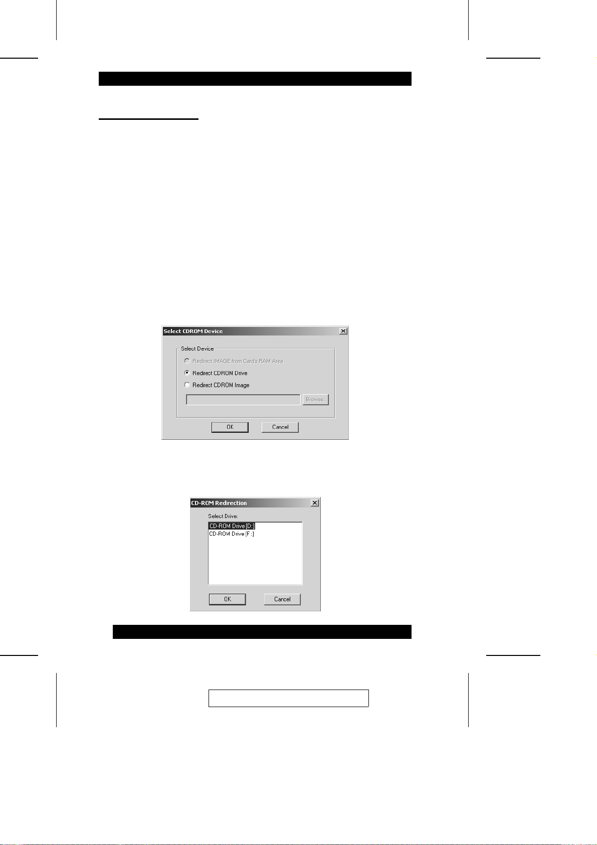
CD Drive Redirection
Starting CD drive redirection:
To perform CD drive redirecti on, do t he following:
1. Use one of the following three methods to invoke the redirection:
M Click the CD Drive Redirection i c on on t he Redirection Toolbar (see p. 51)
M Select CDROM Redirection on the Console Redirection menu (see p. 47)
M Use the Alt+E hotkey combination (see p. 71)
Note: You must be logged in as an administrator on the windows client t o
perform CD-ROM drive redirection.
2. In the dialog box that comes up, select whether you want to redirect the CD-ROM
drive or a CD image file, then click OK.
3. In the dialog box that comes up, select the CDROM drive you want to redire ct,
then click OK. CDROM drive redirection begins immediately.
52
2005-06-09
Page 63

Stopping CD drive redirection:
To stop CD drive redirection, use one of the fol lowi ng thre e methods:
M Click the CD Drive Redirection i c on on t he Redirection Toolbar (see p. 51)
M Select CDROM Redirection on the Console Redirection menu (see p. 47)
M Use the Alt+E hotkey combination (see p. 71)
A dialog box comes up to inform you of the progress:
When the dialog box closes, redirection has ended.
2005-06-09
53
Page 64
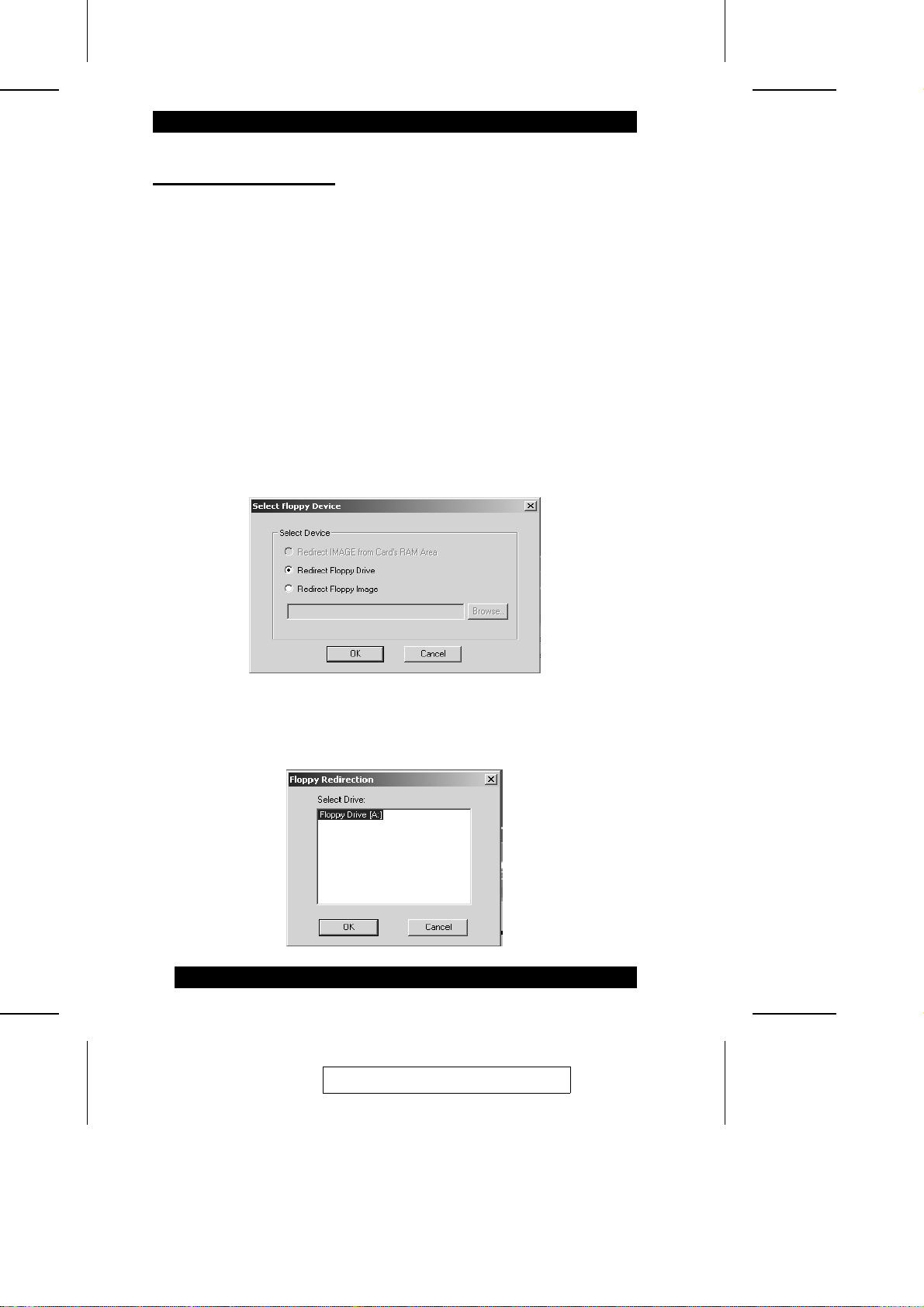
Floppy Drive Redirection
Starting floppy drive redirection:
To perform floppy drive redirecti on, do the following:
1. Use one of the following three methods to invoke the redirection:
M Click the Floppy Drive Redirection ic on on the Redirection Toolbar (see p. 51)
M Select Floppy Redirection on the Console Redirecti on m e nu (see p. 47)
M Use the Alt+P hotkey combination (see p. 71)
Note: You must be logged in as an administrator on the windows client t o
perform floppy drive redirecti on.
2. In the dialog box that comes up, select whether you want to redirect the floppy
drive or a floppy image file, then cli c k OK.
3. In the dialog box that comes up, select the floppy drive you wa nt to redirect, then
click OK. Floppy drive redirection begins immediately.
54
2005-06-09
Page 65

Stopping floppy drive redirection:
To stop floppy drive redirection, use one of the following three methods:
M Click theFloppy Drive Redirection ic on on t he Redirection Toolbar (see p. 51)
M Select Floppy Redirection on the Console Redirecti on m e nu (see p. 47)
M Use the Alt+P hotkey combination (see p. 71)
A dialog box comes up to inform you of the progress:
When the dialog box closes, redirection has ended.
2005-06-09
55
Page 66
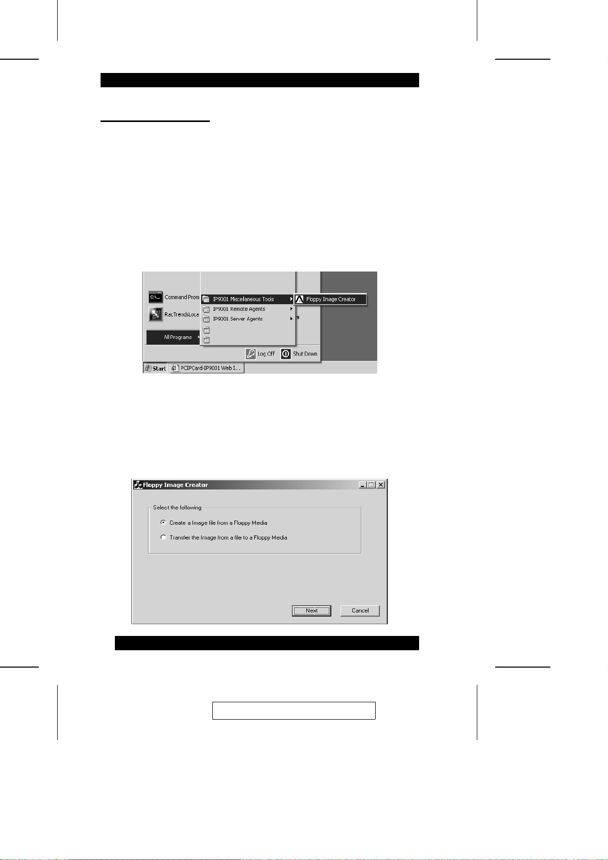
Floppy Image Creation
Using a floppy image file during devi ce redirection is faster and more efficient t ha n
redirecting from an actual floppy disk. It is also more convenient to have a seri es of
floppy images stored on a CD or on a local or ne t worke d hard disk drive than to keep
and maintain actual floppy disks.
To create a floppy image file, do the following:
1. Install the IP9001 utility programs (located on the Software CD that came with
your IP9001 package) on your system.
2. Run the Floppy Image Creator program:
3. In the dialog box that comes up, select Create an Image file from a Floppy Media,
then click Next.
56
2005-06-09
Page 67
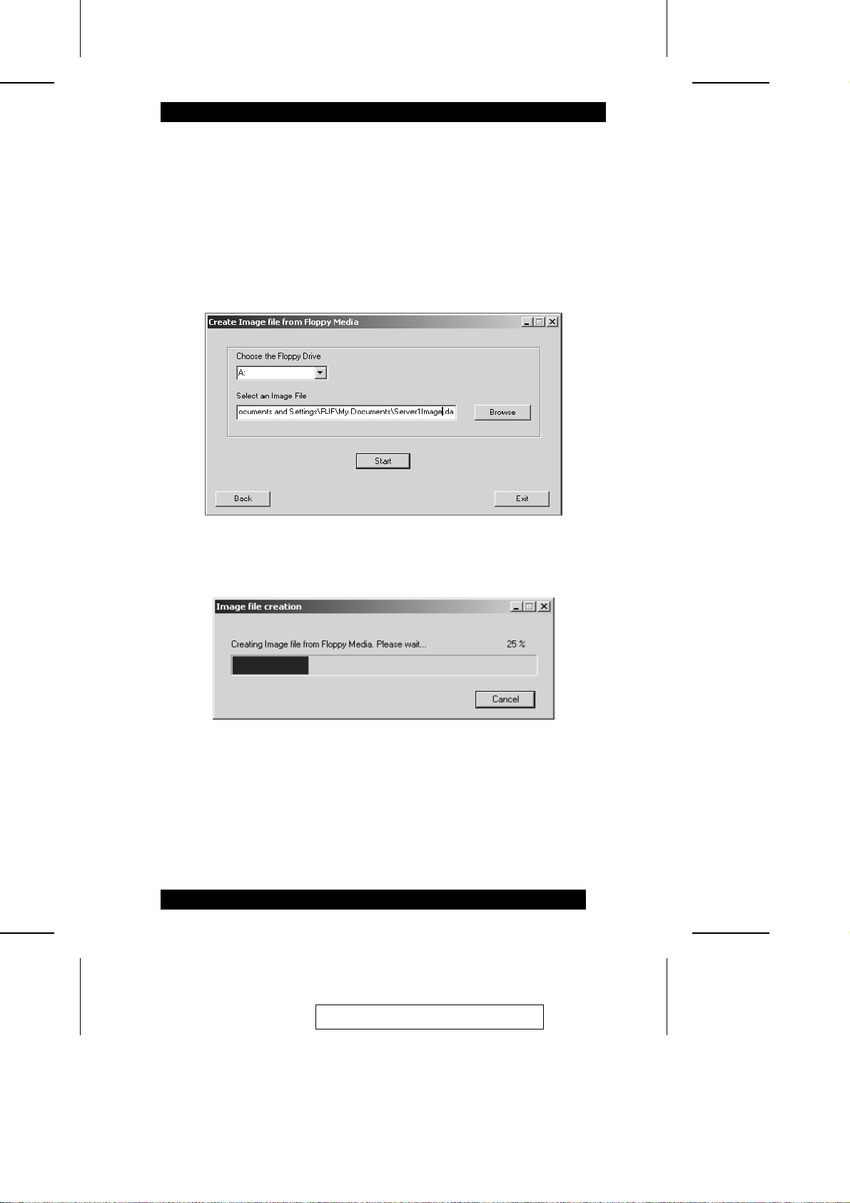
4. In the dialog box that comes up:
a. Select the floppy drive that you want to create the floppy image from
b. Select a location where you want the image to be stored and give it a file nam e
c. Put the floppy with the data you want to copy to the image file in the floppy
drive
d. Click Start
A progress dialog box comes up to indicate the status of the proc edure :
57
2005-06-09
Page 68
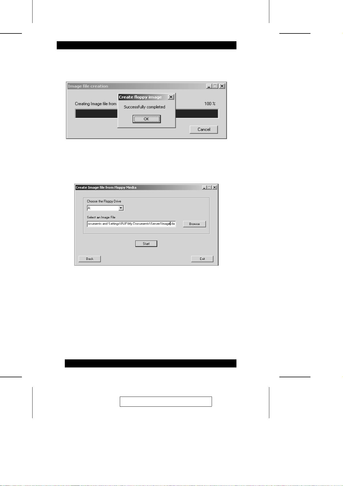
5. Once the image file is successfully created a confirmation dialog box comes up.
Click OK to move on.
6. When the Create Image file from a Floppy Media dialog box comes back up, click
Exit to close the program.
This completes the floppy image fi l e creation procedure. You can now use this image
file during device redirecti on.
58
2005-06-09
Page 69
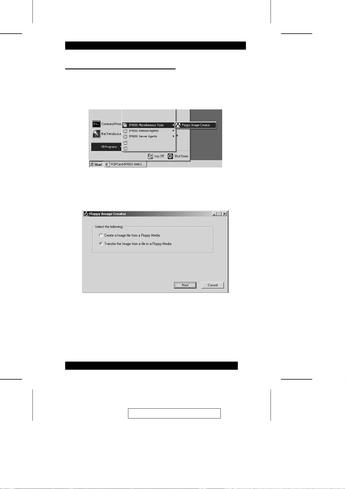
Transfer A Floppy Image To Floppy Disk
To transfer a floppy image to floppy disk, do t he following:
1. Run the Floppy Image Creator program:
2. In the dialog box that comes up, select Transfer the Image from a file to a Floppy
Media, then click Next.
2005-06-09
59
Page 70
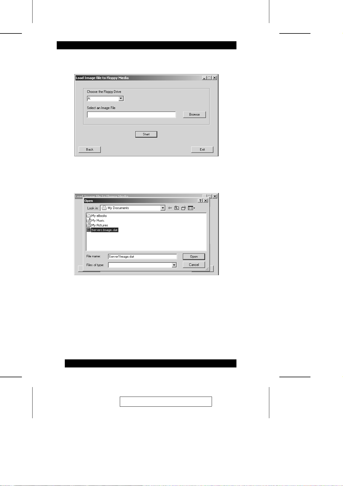
3. In the dialog box that comes up, click Browse.
4. Navigate to the image file you want t o t ra nsfer to the floppy disk, then click Open.
60
2005-06-09
Page 71
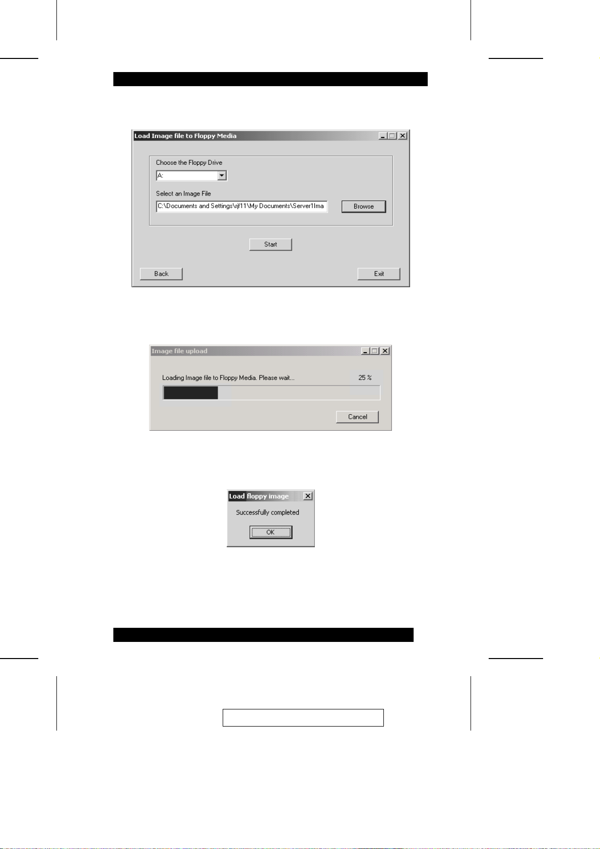
5. In the dialog box that appears, click Start.
A progress dialog box comes up to indicate the status of the proc edure :
6. Once the image file is successfully created a dialog box comes up to indicate so.
Click OK to move on.
2005-06-09
61
Page 72
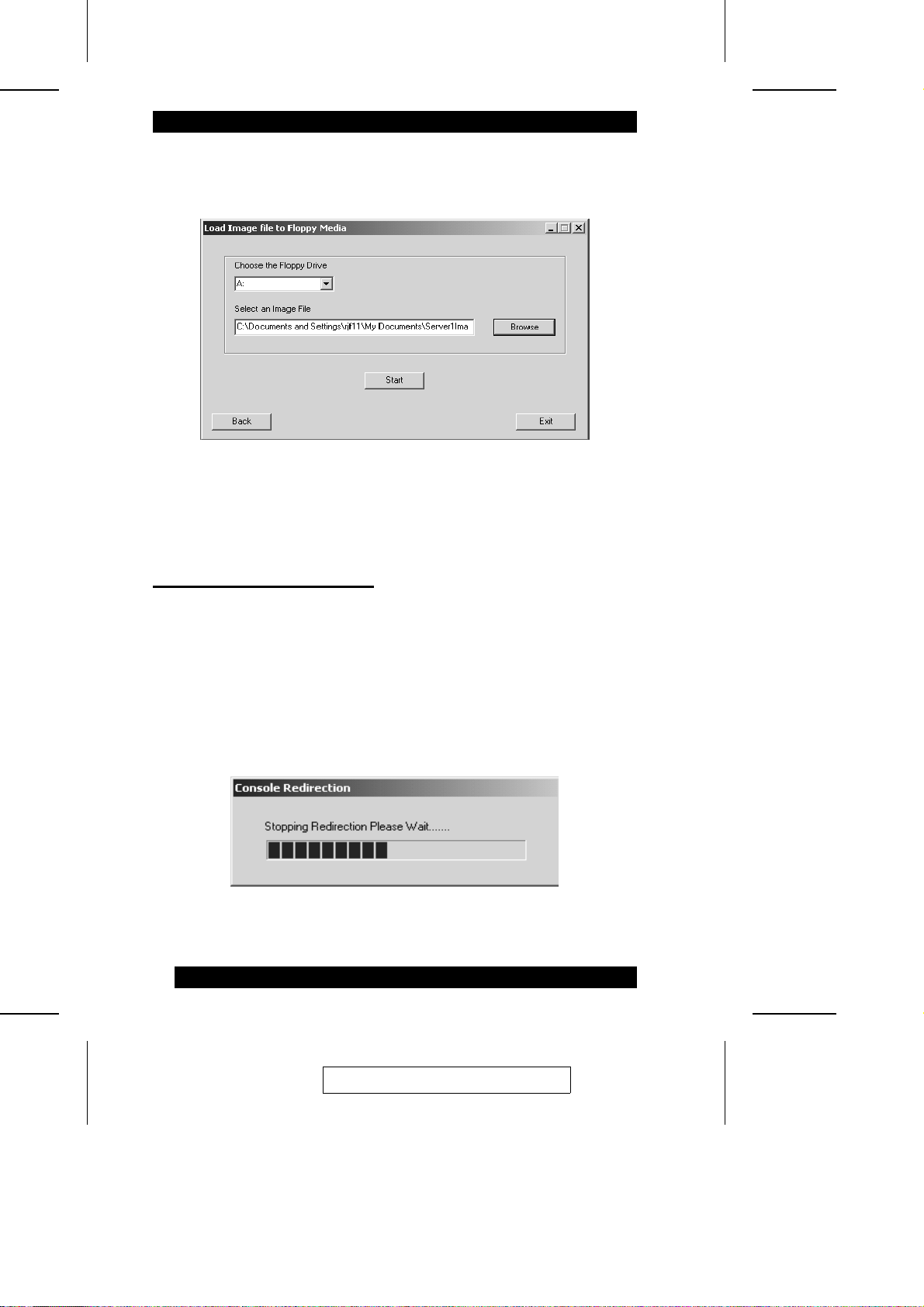
7. When the Load Image file to a Floppy Media dialog box comes back up, click
Exit to close the program.
This completes the floppy image fi l e t ra nsfe r t o fl oppy m e di a procedure.
Stopping Console Redirection
To stop console redirection, use one of the followi ng thre e methods:
M Click the Stop Redirection icon on the Redirection Toolba r (se e p. 51)
M Select Stop Console Redirection on the Console Redirection menu (see p. 47)
M Use the Alt+T hotkey combination (see p. 71)
A dialog box comes up to inform you of the progress:
When the dialog box closes, redirection has ended.
62
2005-06-09
Page 73
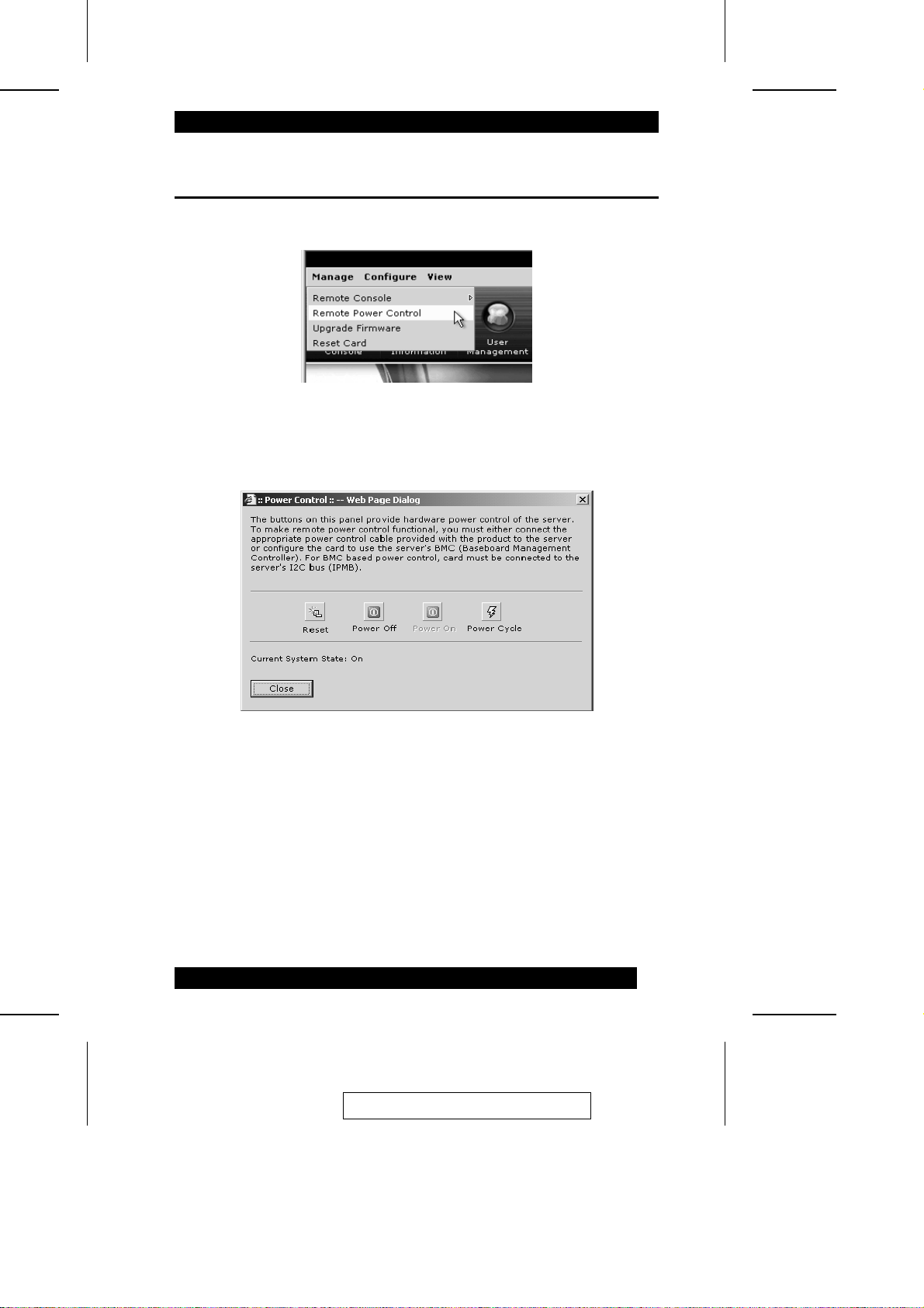
Remote Power Control
The second item on the Manage menu is Remote Power Control :
The Power Control dialog box allows you to remotely rese t, powe r off, power on, and
power cycle the host system:
Simply click the icon to perform the corresponding action on the remote syst em. The
entry below the icons indicates the remote system’s current power status (Off or On).
2005-06-09
63
Page 74
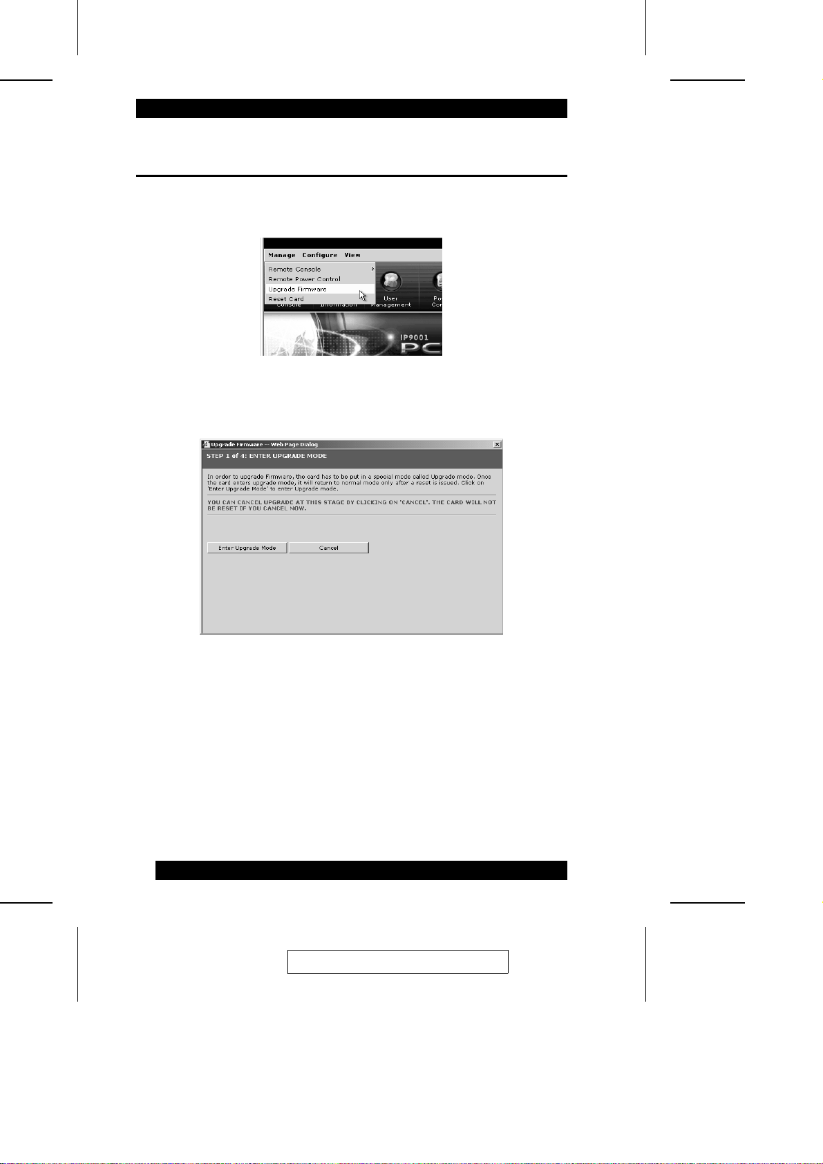
Upgrade Firmware
The Upgrade Firmware utility provides an easy, convenient method to upgrade the
IP9001’s firmware:
To begin, click the Upgrade Firmware entry on the Manage menu to bring up the
opening dialog box:
Note: 1. Upgrading the firmware is a criti cal procedure. Make sure that the chances
of a power or connectivity loss are minimal when performi ng thi s ope ra tion.
2. If you click Cancel at this time to abort the upgrade process, the IP9001
card resets itself.
3. If you cancel after you have entered Upgrade Mode, the IP9001 card must
be reset by closing the Internet browser and then logging ba ck ont o the
IP9001 in a new browser session.
64
2005-06-09
Page 75
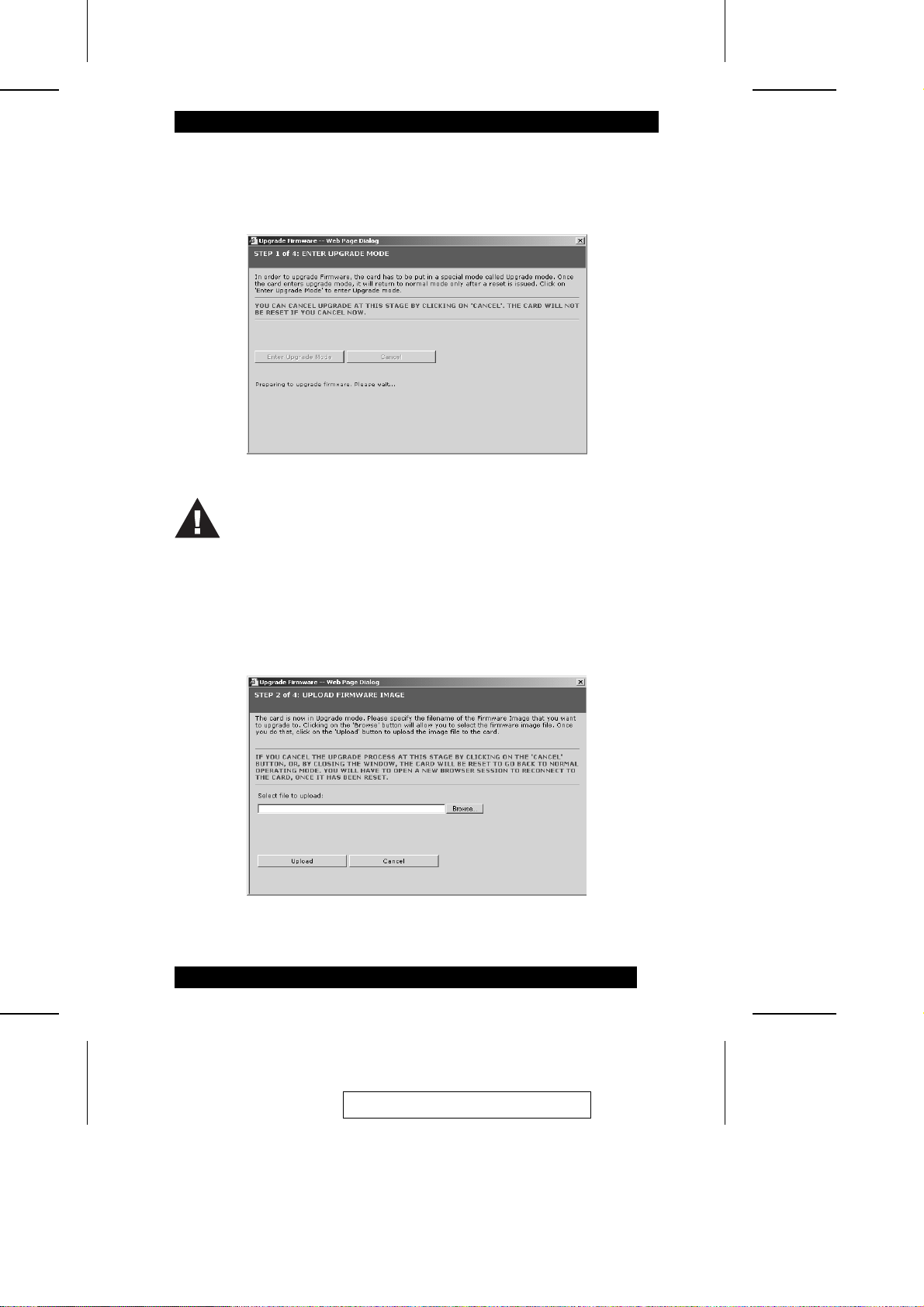
To update the IP9001’s firmware, do the foll owing:
1. Click Enter Firmeare Upgrade Mode. The following dial og box a ppears:
When the IP9001 is in Upgrade Mode and you want to abort the procedure,
you must use the Cancel button to close the upgrade dialog boxes. DO NOT
use the Title Bar’s X button to close the dialog boxes.
2. In the dialog box tha comes up, click Browse to navigat e t o whe re the firmware
upgrade file (*.IMA) resides:
65
2005-06-09
Page 76
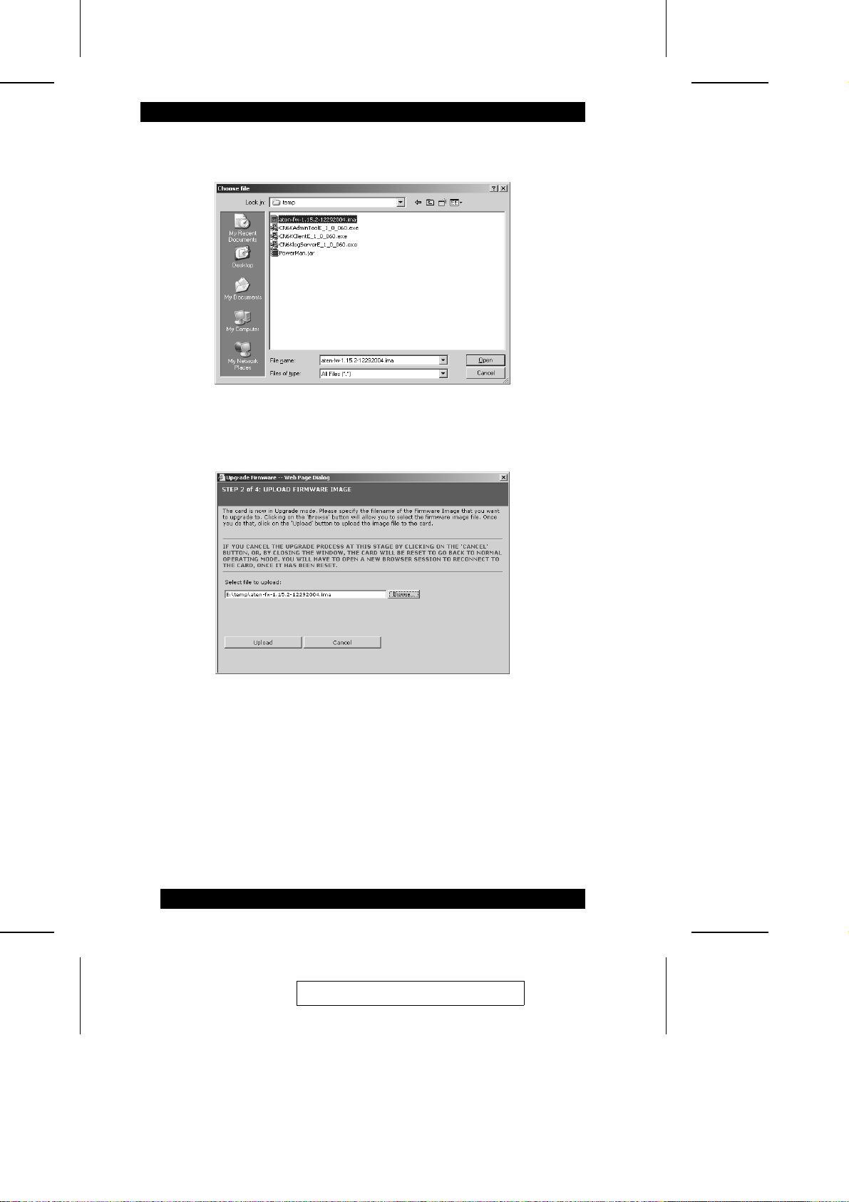
3. Select the image file (it has an ima extension), then click Open.
4. In the dialog box that comes up, click Upload.
66
2005-06-09
Page 77
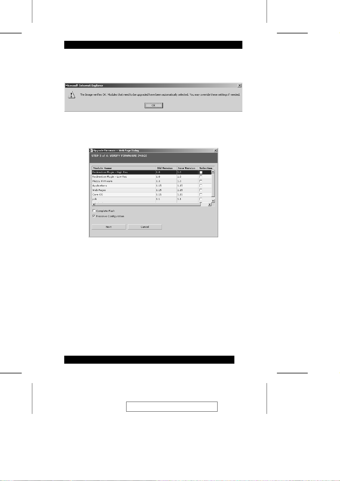
5. The upgrade utility starts the upload of the new firmware file and checks it for
integrity. After it verifies the image file, it displays the following message:
Click OK to move on.
6. A dialog box comparing the old and new versions appears:
M To upgrade some components but not others, check the component you want
to upgrade in the Selection column.
M To upgrade all the components, check Complete Flash.
M To upgrade, but retain a copy of your original configuration, check Preserve
Configuration.
When your selections have been made, clic k Next to move on.
Note: If you choose to cancel the upgrade, the IP9001 card must be reset by
closing the Internet browser and then logging back onto the IP9001 in a
new browser session.
2005-06-09
67
Page 78
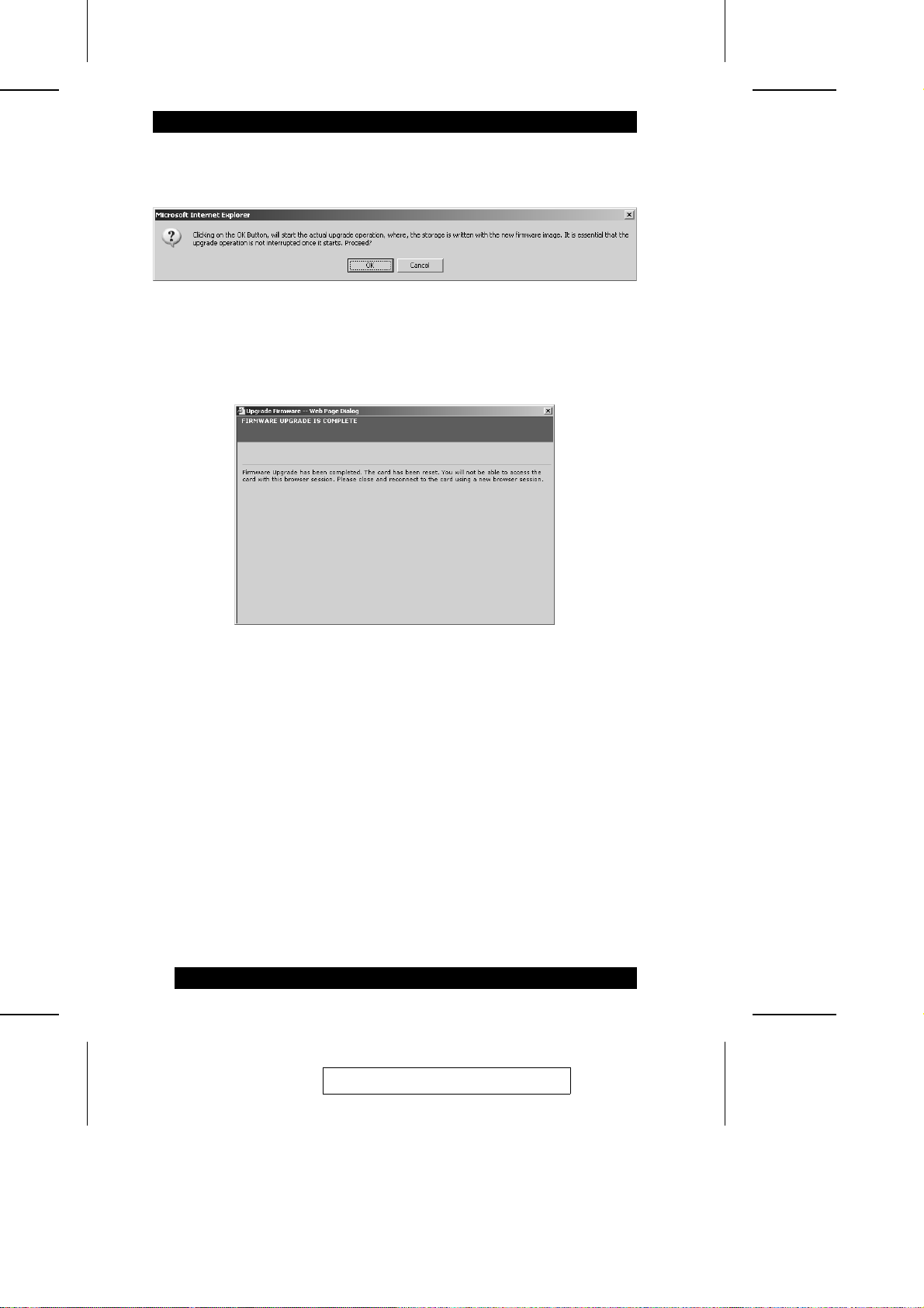
7. A confirmation dialog box comes up. Click OK to start the actual upgrade.
8. A screen showing the upgrade progress comes up. After the procedure has
successfully completed the following screen appears:
You must now close your browser and log back onto the IP9001 in a new browser
session.
68
2005-06-09
Page 79
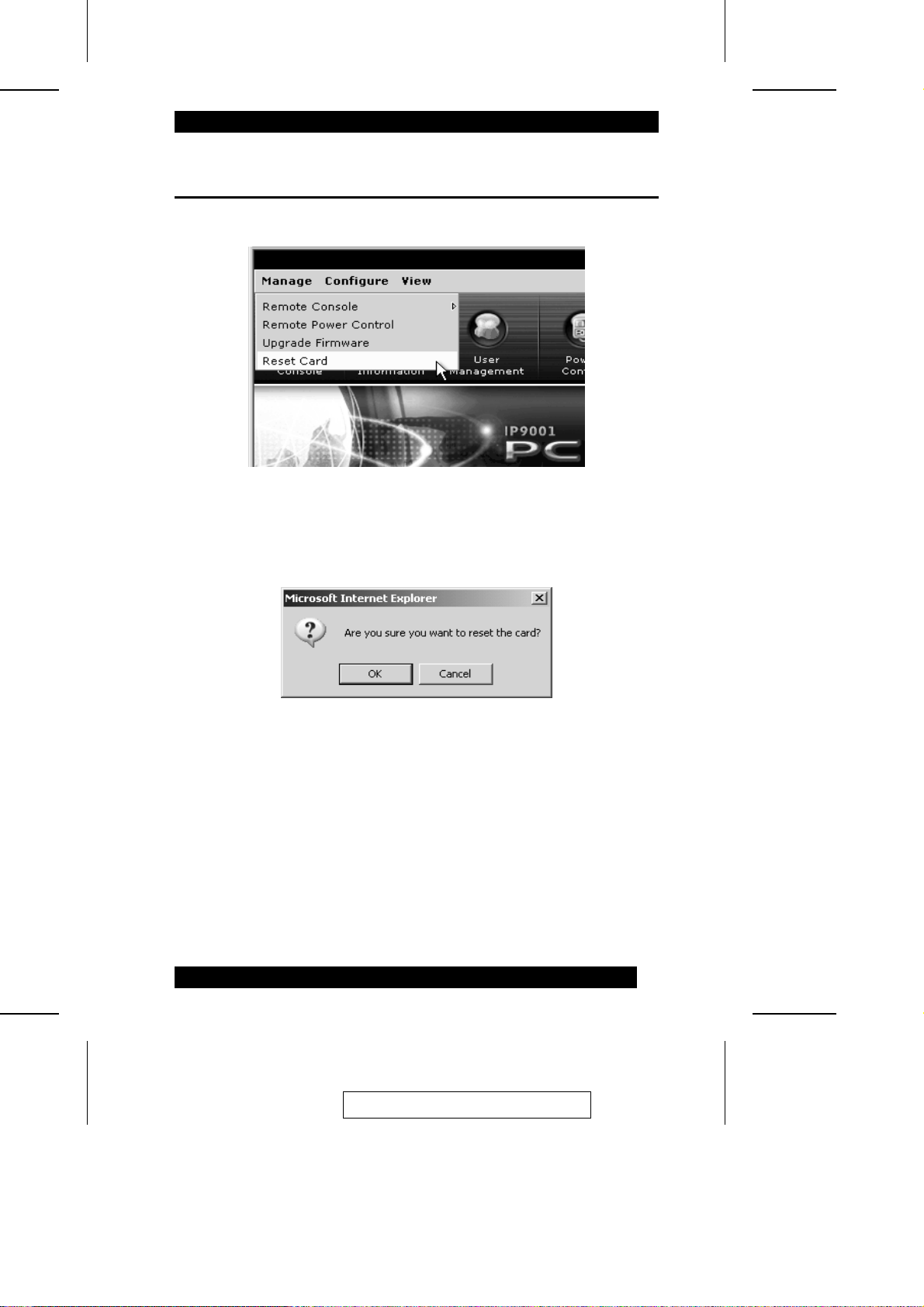
Reset the IP9001
The function of this menu item i s t o re se t t he IP9001:
1. When you click Resert Card on the Manage menu, a confi rmation dialog box
comes up. Click OK to reset the card:
2005-06-09
69
Page 80

2. When the reset procedure is complete, the following dialog box appears.:
Close your browser and relog into the IP9001 in a new browser session.
70
2005-06-09
Page 81

Remote Console Hotkey Combinations
The following table lists hotkey combinations tha t pe rform many of the remote
console functions directly from the keyboa rd.
Hotkey Function
ALT + S
ALT + T
ALT + R
ALT + F
ALT + M
ALT + A
ALT + B
ALT + L
ALT + N
ALT + D
ALT + E
ALT + P
Start Console Redirection
Stop Console Redirection
Restart Console Redirection
Toggle Full Screen Mode
Synchronize Mouse
Hold/Release Right Alt Key
Hold/Release Left Alt Key
Hold/Release Right Ctrl Key
Hold/Release left Ctrl Key
Generate Ctrl + Alt + Del
Start CDROM Drive Redirection
Start Floppy Drive Redirection
2005-06-09
71
Page 82

Notes:
72
2005-06-09
Page 83
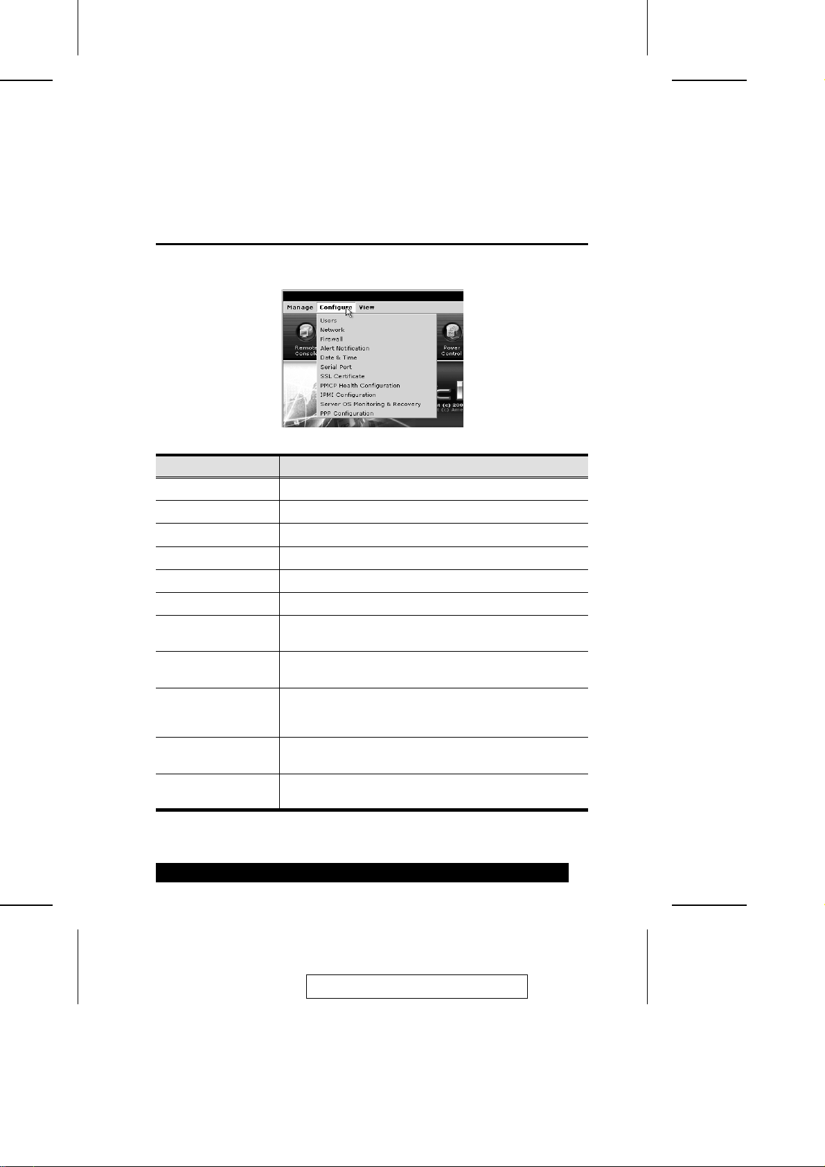
Chapter 6.
The Configure Menu
Overview
When you click Configure on the menu bar, its subm enu drops down:
Item Function
Users Administer users that can access the IP9001 and host system.
Network Configure the IP9001’s network parameters.
Firewall Control which IP addresses can access the IP9001.
Alert Notification Configure how alerts are sent.
Date & Time Configure the IP9001’s date and time settings.
Serial Port Configure the IP9001’s Serial Over LAN access.
SSL Certificate Upload a Digital Certificate and Private Key to the IP9001 card.
PMCP File Upload Upload a platform management file for your
IPMI Configuration Configure the IP9001 card to read data from an onboard
Server OS Monitoring
& Recovery
PPP Configuration Set the PPP addresses for the Server and Client when
Note: Pass-phrase encrypted certificates are not supported.
motherboard/server board.
baseboard management controller (BMC) on the
motherboard/server board.
Configure operating system monitoring and recovery
methods.
using a modem.
2005-06-09
73
Page 84
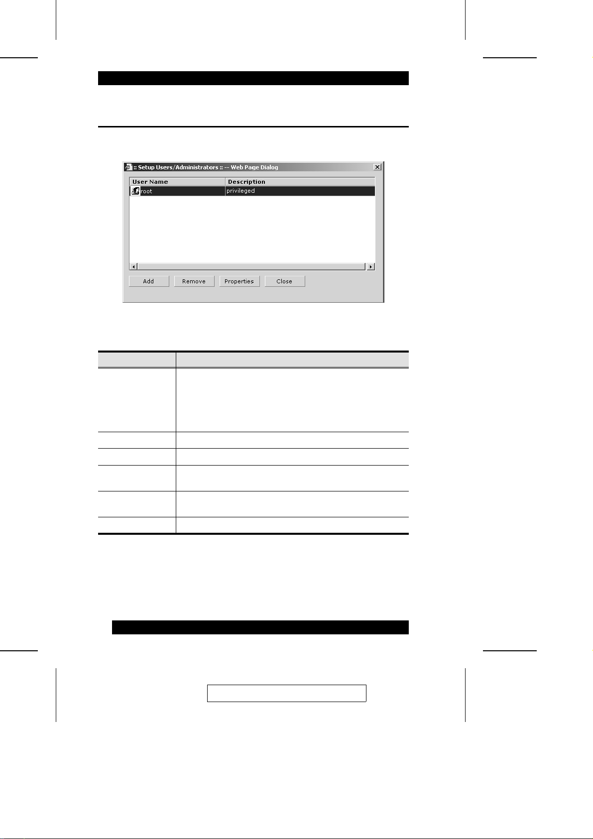
Users
Clicking Users on the Configure me nu bri ngs up t he Use r setup dialog box:
The dialog box screeen elements are described i n t he t a ble below.
Element Function
Username User’s log in name.
Note: The default administrator’s Username is root; the default
administrator’s password is superuser. For security purposes,
we strongly recommend that you change the default password
to something unique.
Description Descriptive information about the user.
Add Click to add a new user account.
Remove Click to delete the user account currently selected in the
Properties Click to View/Edit the user account currently selected in the
Close Click to exit the User Administation dialog box.
Username list.
Username list.
74
2005-06-09
Page 85
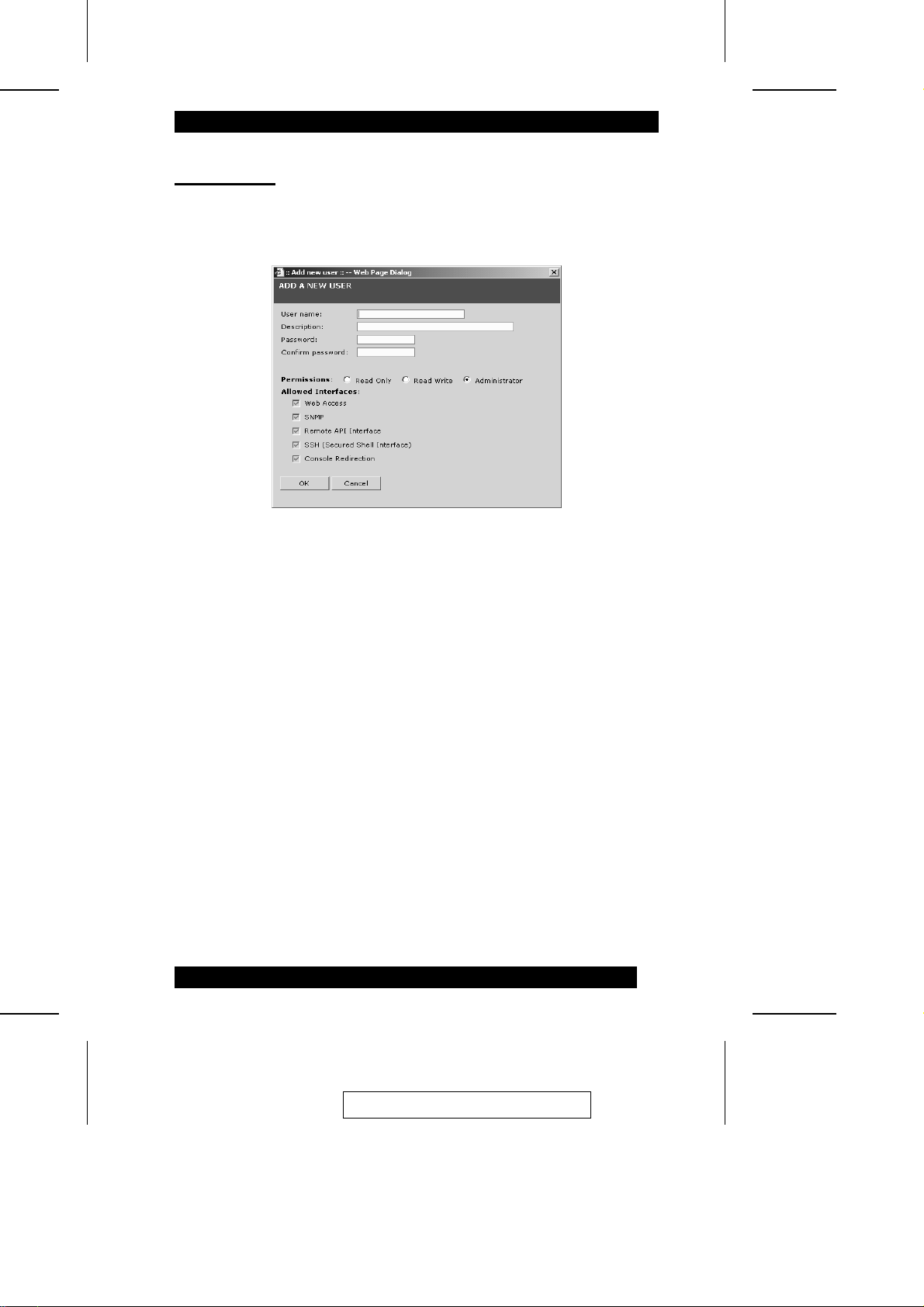
Adding Users
To add a user account, do the following:
1. In the User dialog box, click Add. The Add a New User dialog box a ppe a rs:
2. Key the appropriate information into the Username, Description, Password and
Confirm Password fields. Please note the following:
M User names are case sensitive. They can consist of any combination of
alphanumeric characters but they must start with an alphabetic character, and
must be between 4 and 12 charac t e rs l ong.
M Entering a remark in the Description field is optional.
M Passwords are case sensitive. They must be between 8 and 16 characters long.
For security purposes, we recommend using a combination of alpha be tic and
numeric characters.
M Confirm the password by entering it again in the Confirm Password field.
3. Assign the user’s permissions and allowed interfaces:
M Only users with Administrator permissions are allowed to add, edit , and
remove users. Non-administrator use rs can onl y cha nge their own password.
M Users with Administrator permissions are automatically granted access to all
interfaces.
2005-06-09
75
Page 86
Removing Users
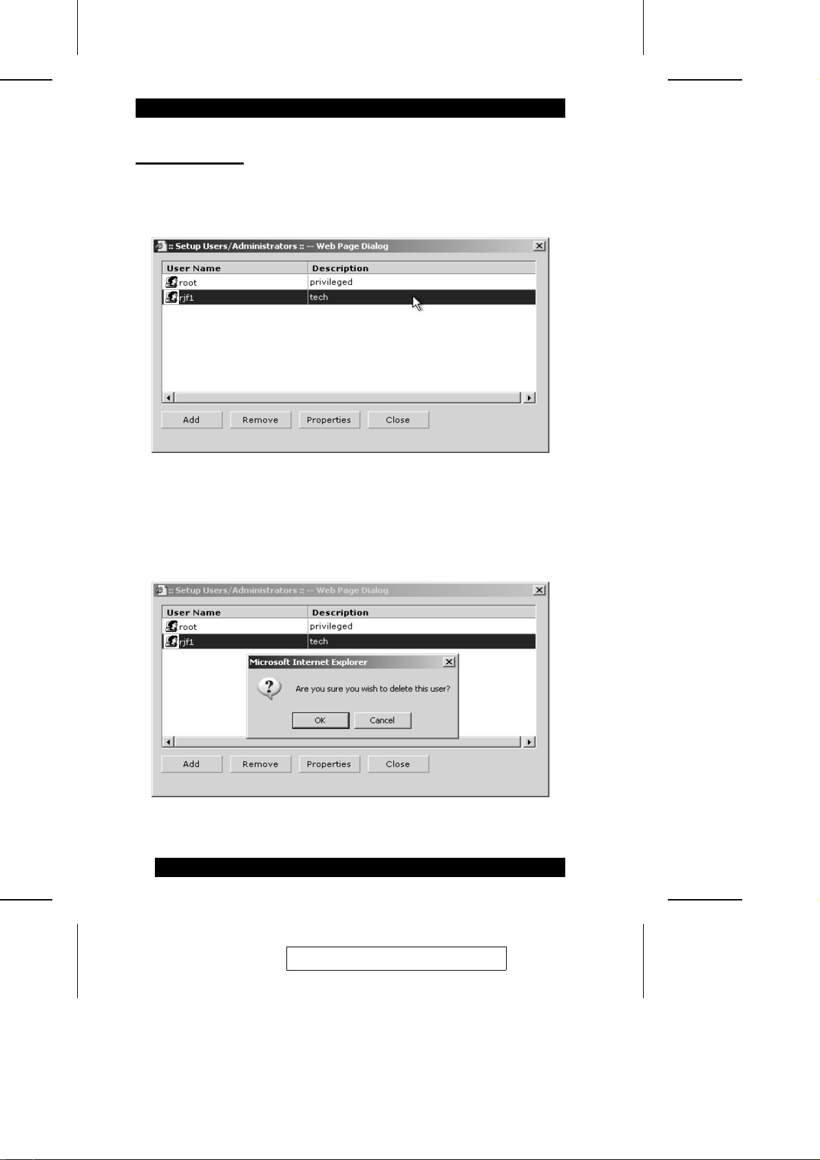
To delete a user account, do the following:
1. Select the account to be removed from the User Name list.
2. Click Remove.
3. In the confirmation dialog box that comes up, click OK to confi rm the deletion, or
click Cancel to abort the procedure.
76
2005-06-09
Page 87
Viewing and Editing Users
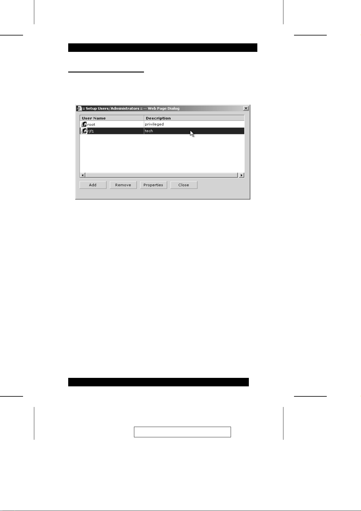
To view and/or edit a user account, do the following:
1. Select the account from the User Name list.
2. Click Properties.
The Modify User dialog box comes up. This dialog box is similar to the Add a
New User dialog box on p. 75. Refer back t o the field descriptions given there, i f
necessary.
3. After you have made your changes, click OK to complete the proc edure, or click
Cancel to abort the procedure without saving your changes.
2005-06-09
77
Page 88
Network
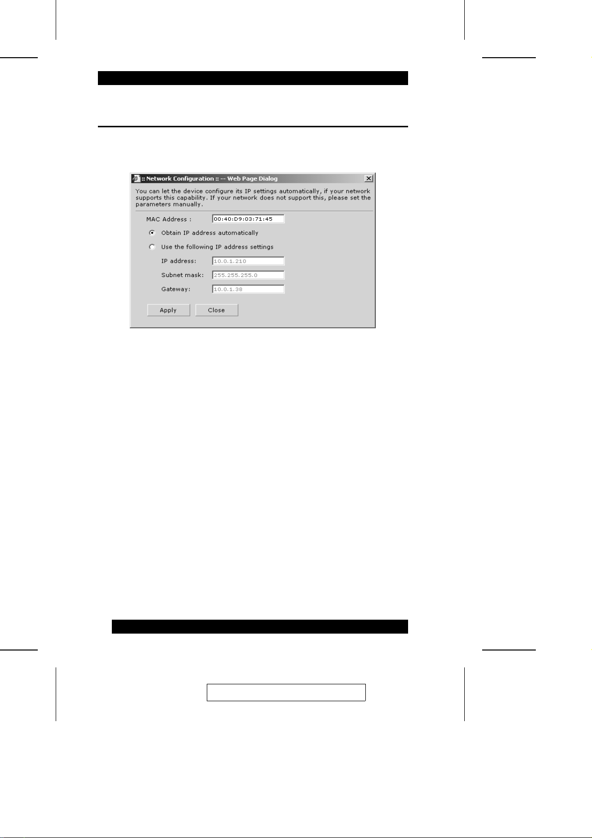
Clicking Network on the Configure m e nu brings up the Network Configuration dialog
box:
M The IP9001’s MAC address displays in the MAC Address field.
M If you want the IP9001 to get its IP address dynamically (from a DHCP server),
select Obtain IP address automatically.
M If you want to assign a static IP address to the IP9001, select Use the following IP
address settings, then fill in the IP address, Subnet mask, and Ga t e way fields with
entries that are appropriate for your network.
When you have finished making your entri e s, cl i c k Apply t o sa ve your changes. To
abort the procedure without saving your change s, click Close.
Note: If you change the information in the Network Configuration dial og box, you
are prompted to close your browser and reconnect to the IP9001 at its new IP
address.
78
2005-06-09
Page 89
Firewall
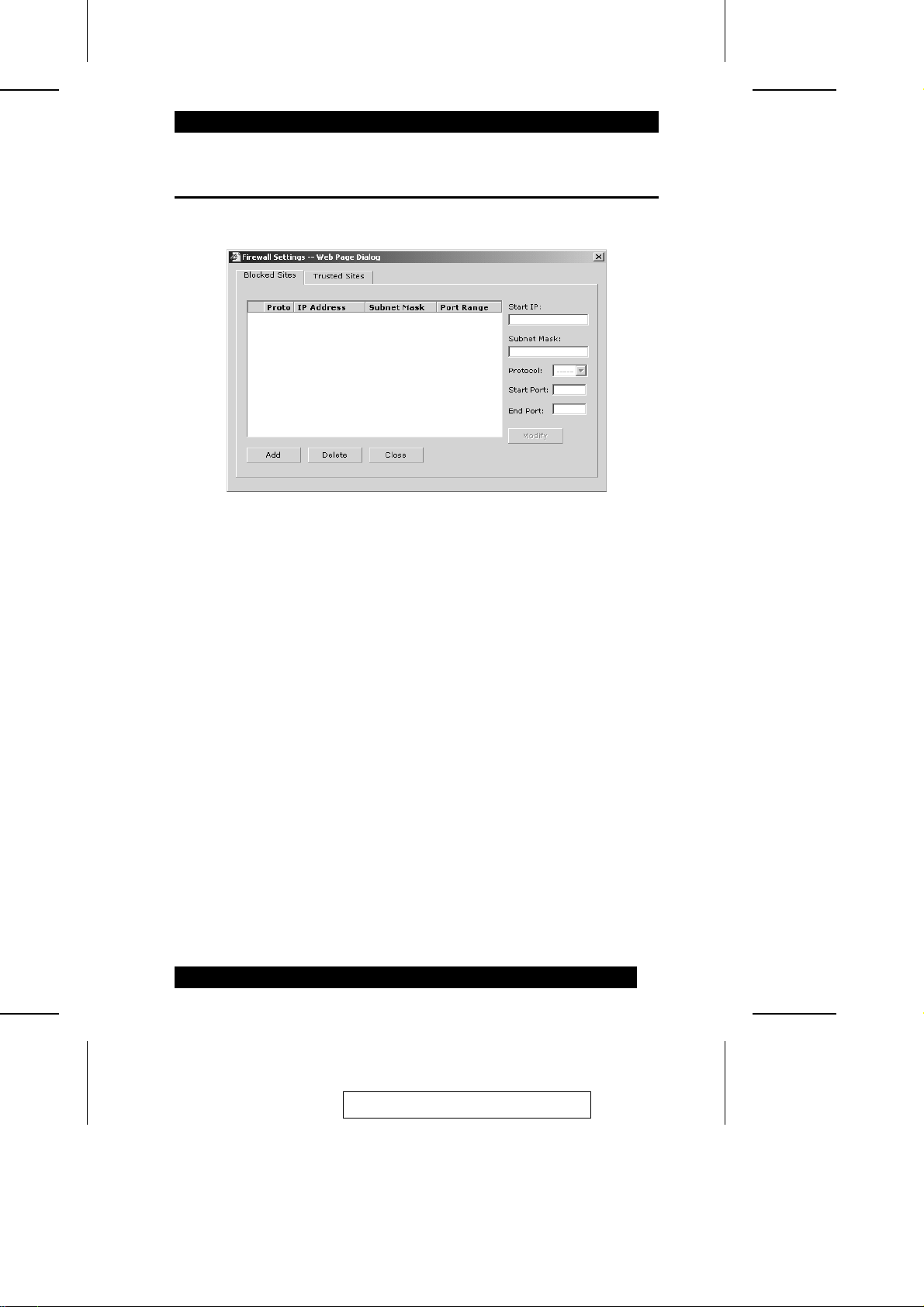
Clicking Firewall on the Configure menu brings up the Firewall Settings dialog box:
This dialog box allows you to configure the IP9001’s access parameters, by entering
IP addresses and ports to block or allow.
M Click the Blocked Sites tab to enter a range of addresses that you want to block.
M Click the Trusted Sites tab to enter a range of addresses that you want to always
allow.
2005-06-09
79
Page 90
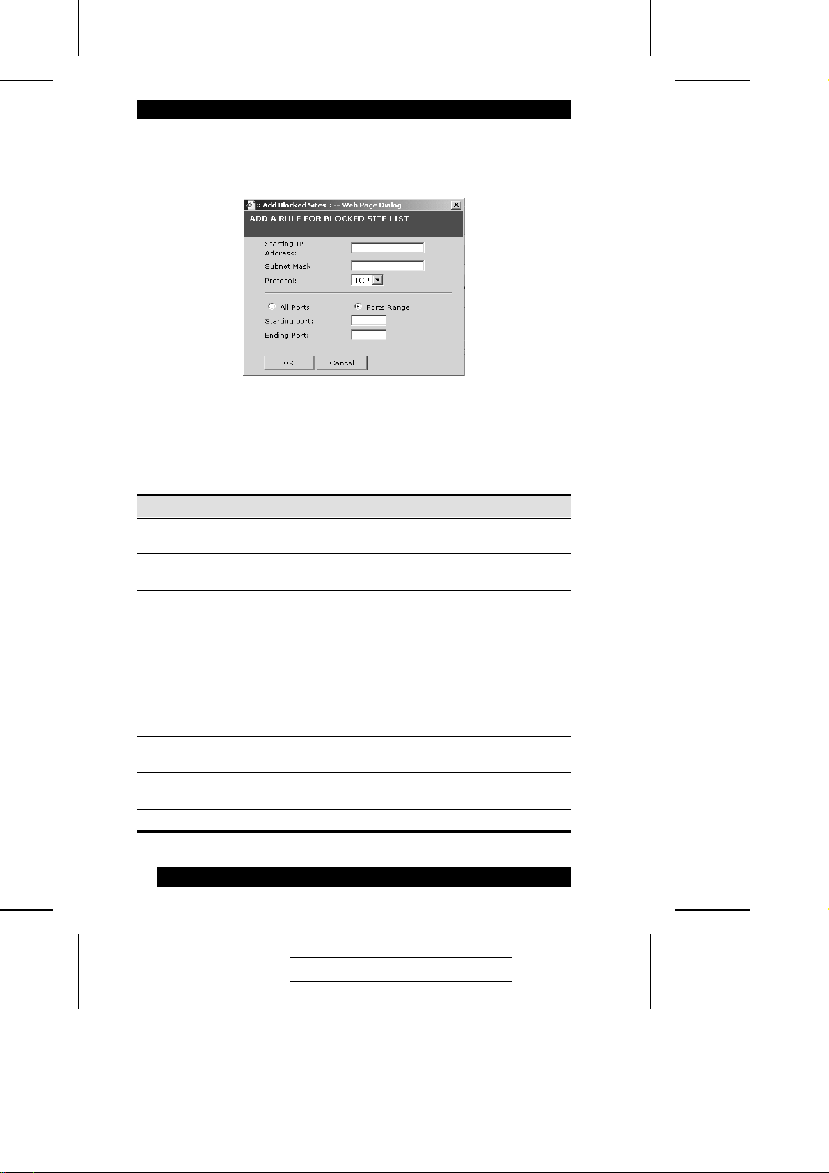
After you click Add for either the Blocked or Trusted site, the Add a Rule dialog box
comes up:
Note: The dialog box shown is for Blocked sites. The dialog box for Trusted sit es
has the same fields, so the descriptions that follow also apply to the dialog for
Trusted sites.
Field Function
Start IP Address This field allows you to enter the start IP address of the subnet
Subnet Mask This field allows you to enter the specific subnet of the IP
Protocol This drop down list lets you select a protocol (UDP or TCP)
All Ports If this is enabled, the IP9001 will accept or ignore data on all
Port Range If this is enabled, you can select a specific range of ports that
Starting Port This field allows you to enter the the first port of the range that
Ending Port This field allows you to enter the last port of the range that you
[OK] Click OK when you are satisfied with the information you
[Cancel] Click Cancel to discard your changes and exit.
you want to block or always allow.
address range that you want to filter.
that the IP9001 will either accept or ignore.
ports (1 through 65535).
you want the IP9001 to accept of ignore.
you want the IP9001 to accept or ignore.
want the IP9001 to accept or ignore.
entered.
80
2005-06-09
Page 91
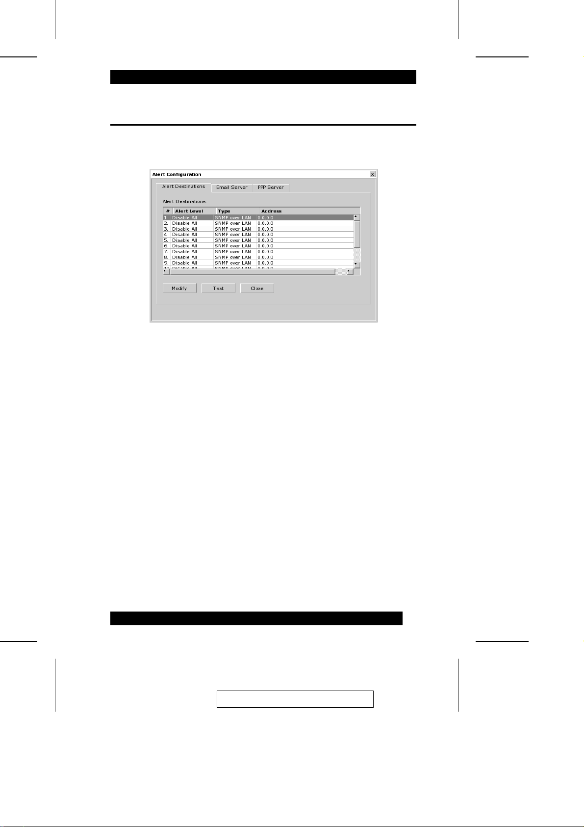
Alert Notification
Clicking Alert Notification on the Configure menu brings up the Al ert Notification
dialog box:
This dialog box lets you configure where and how various al ert s from t he IP9001 are
sent.
2005-06-09
81
Page 92
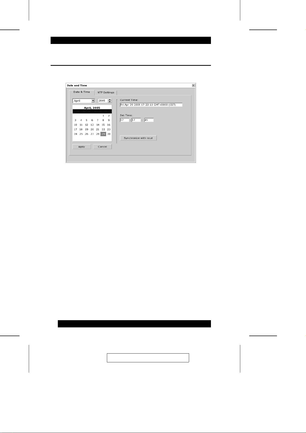
Date & Time
Clicking Date & Time on the Configure m e nu bri ngs up t he Date & Time dialog box:
Use this dialog box to set the IP9001’s date and time. You can set the time manually,
synchronize it with your local machine; or ha ve i t sync hronized with an NTP
(Network Time Protocol) server.
82
2005-06-09
Page 93
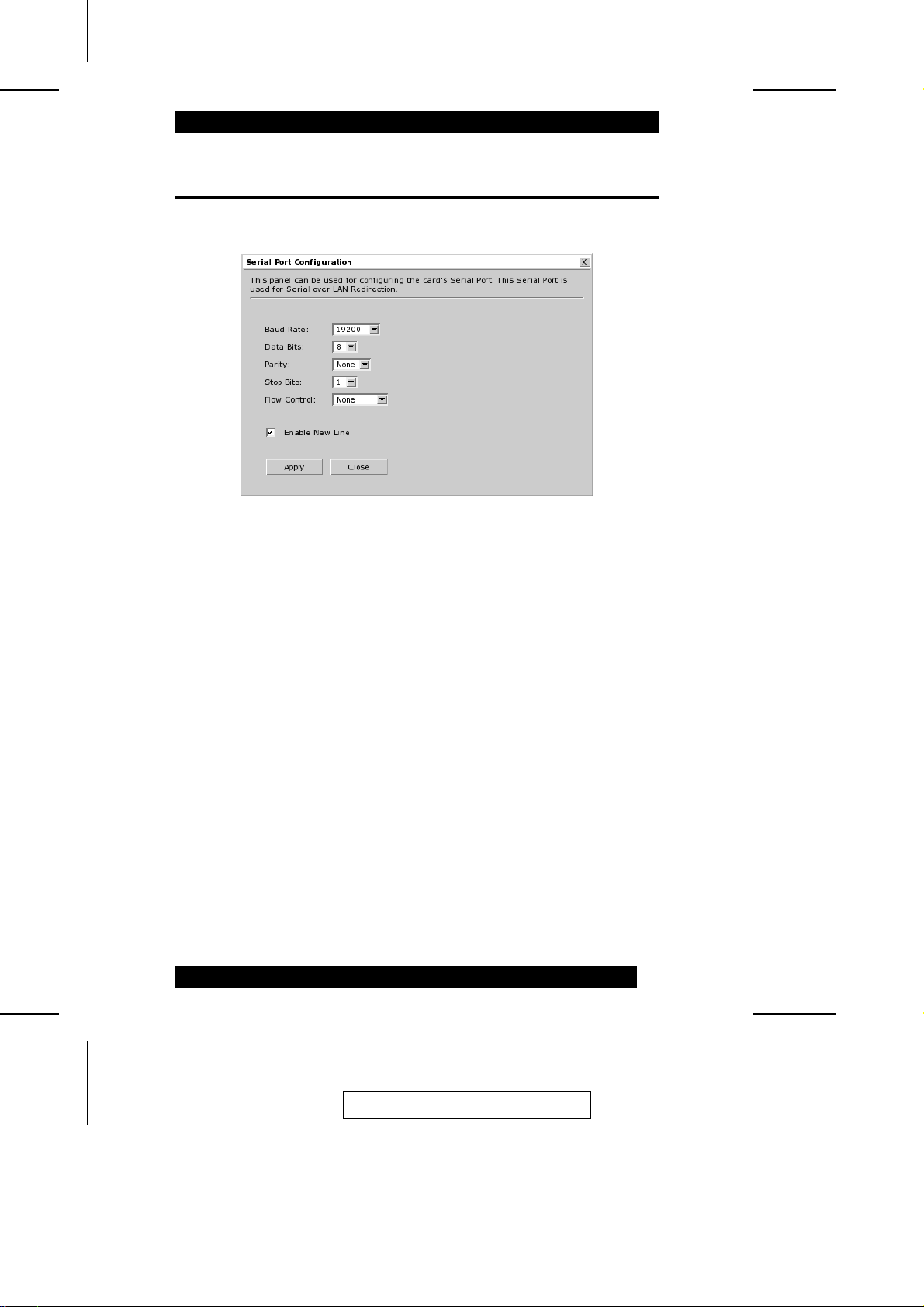
Serial Port
Clicking Serial Port on the Confi gure menu brings up the Serial Port dialog box:
Use this dialog box to set the serial port parameters: baud rate, data bits, parity, stop
bits, and flow control.
2005-06-09
83
Page 94
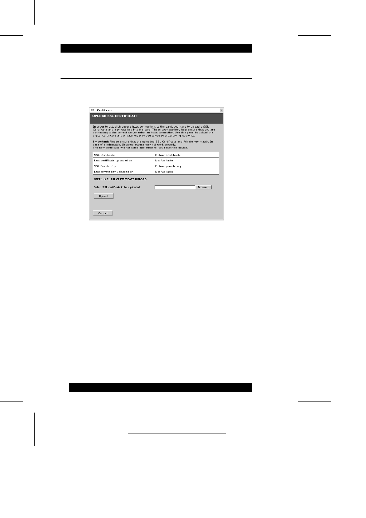
SSL Certificate
Clicking SSL Certificate on the Configure menu bri ngs up t he SSL Certificate dialog
box:
Use this dialog box to upload an SSL Certificate and SSL Private Key for verification
when users access the IP9001 with their browsers.
Click the Browse button to navigate to where your Certificat e and Pri va t e Key files
are located - both files have a PEM file extension.
Note: The IP9001 does not support pass-phrase encrypted certificates.
After both files are uploaded a dial og com e s up re m i nding you that the IP9001 needs
to be reset for the new certi ficates to take effect. Click OK to reset the card.
Now, users can securely access the IP9001 with a format similar to the following:
https://[the IP9001’s IP address]
84
2005-06-09
Page 95
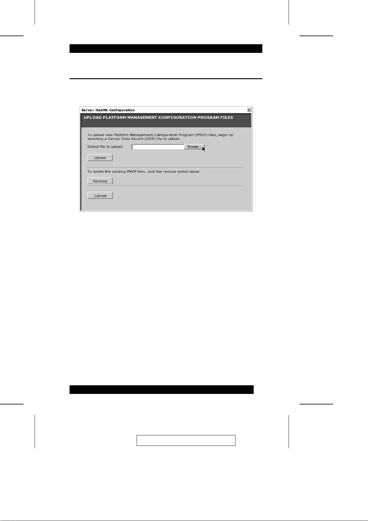
PMCP File Upload
Clicking PMCP Health Configuration on the Configure menu brings up the The Host
Health Monitoring Files dialog box.
This is the same dialog box, and involves the same procedure s di sc usse d in Cha pter 2,
p. 34, under Load the SDR and Soft Processor (SP) File.
Follow the steps on those pages to complet e t hi s proc edure .
2005-06-09
85
Page 96
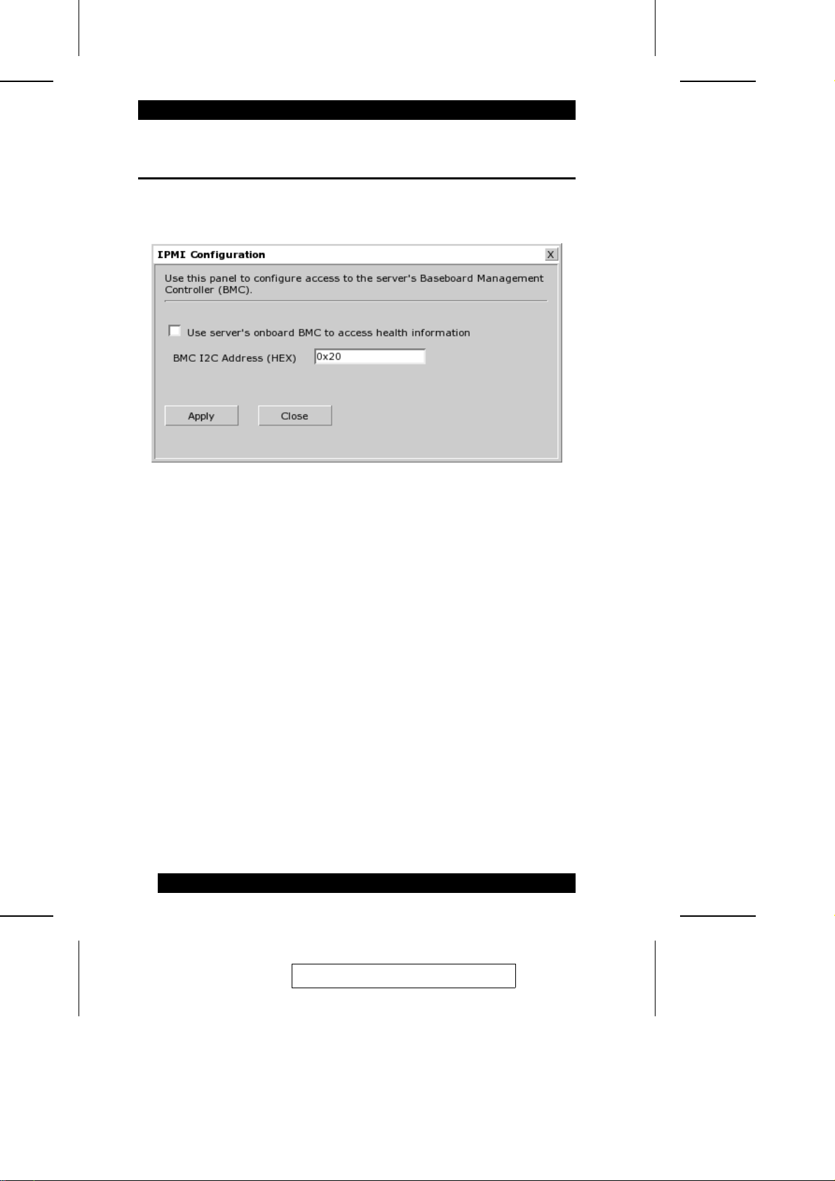
IPMI Configuration
Clicking IPMI Configuration on the Confi gure menu brings up the IPMI
Configuration dialog box:
To read data from an onboard baseboard ma na ge m e nt controller (BMC) on the
motherboard/server board, put a che c k i n the the checkbox, then click Apply.
86
2005-06-09
Page 97
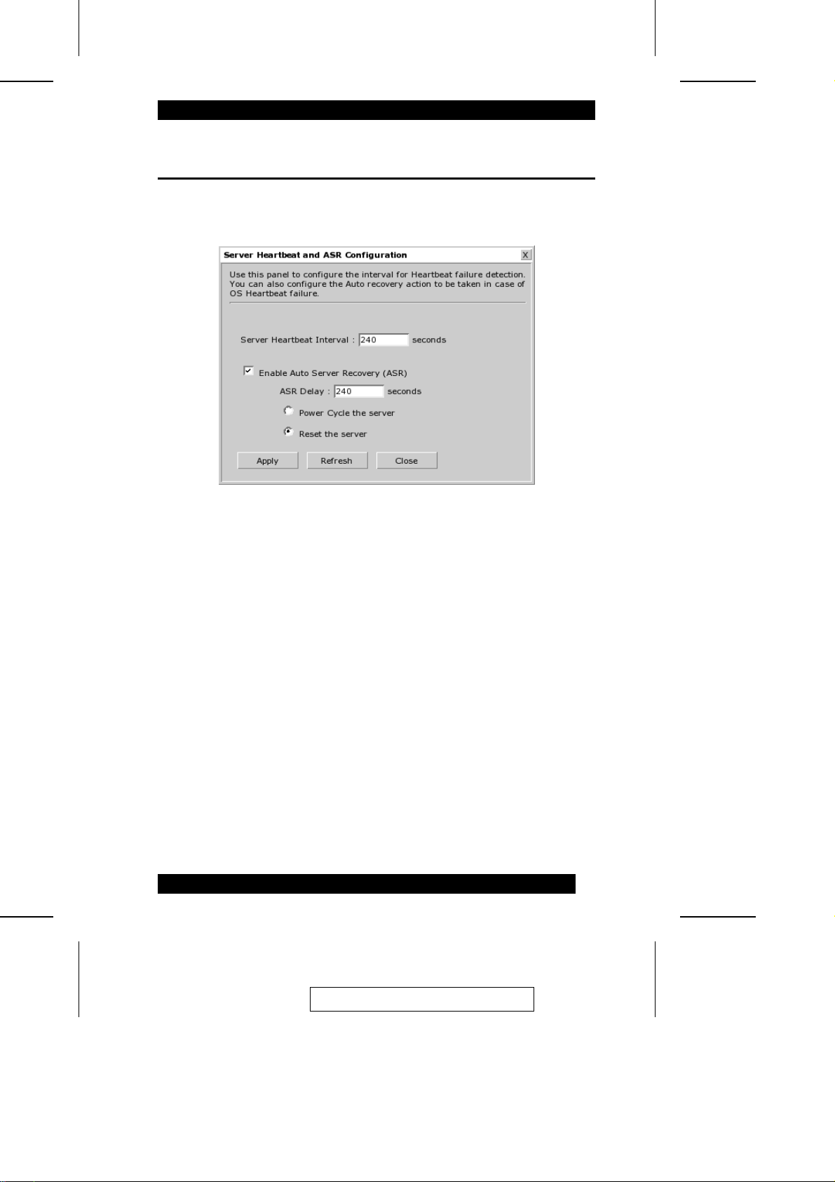
Server OS Monitoring and Recovery
Clicking Server OS Monitoring and R ecov e ry on t he Confi gure menu brings up the
Server OS Monitoring and Recovery dialog box:
This dialog box allows you to configure operating system monitoring and re cove ry
methods.
2005-06-09
87
Page 98
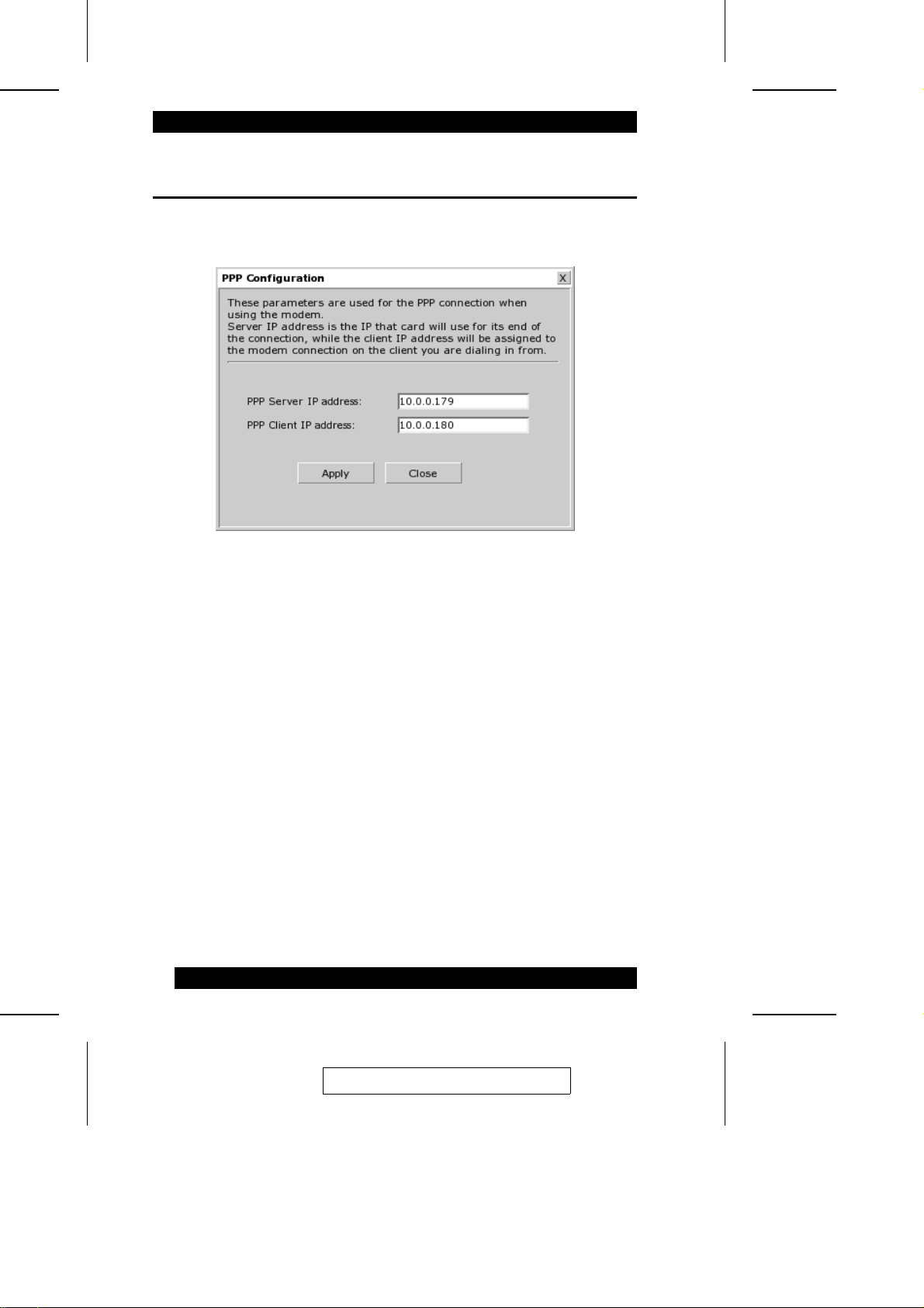
PPP Configuration
Clicking PPP Configuration on the Configure menu brings up the PPP Confi gura tion
dialog box:
This dialog box allows you to set the PPP addresses for the Server and Client when
using a modem.
88
2005-06-09
Page 99

Chapter 7.
The View Menu
Overview
When you click View on the menu bar, its submenu drops down:
A brief description of the items is given in the table below: Each item is explained in
detail in the sections that follow.
Item Function
Card Health Shows health information for the IP9001.
Event Log Allows you to view and clear the event logs.
Server Health Shows the host system’s health information based on the
General Information Shows general information about the IP9001.
Last Saved Crash
Screen
sensor readings and platform management configuration
information.
Shows the last text screen on the host system before it
locked up.
2005-06-09
89
Page 100
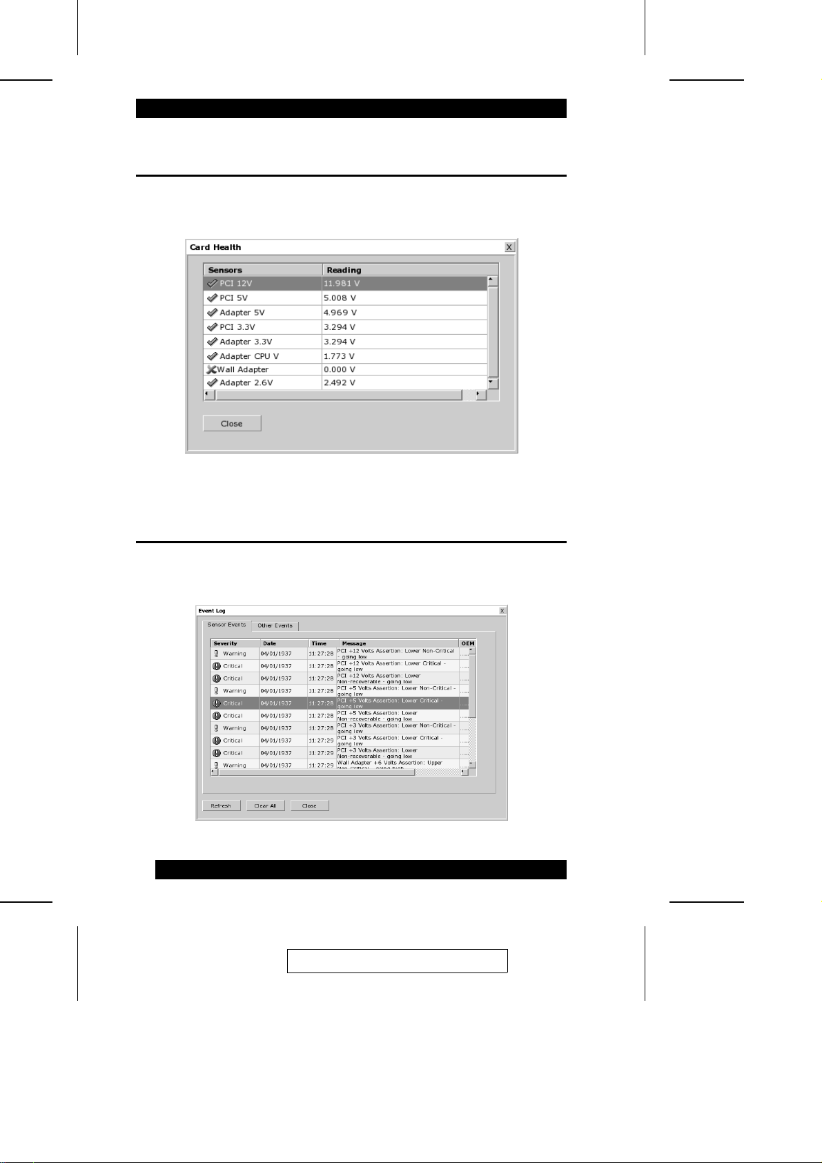
Card Health
Clicking Card Health on the View menu brings up a screen that shows the IP9001’s
health information:
Event Log
Clicking Event Log on the View menu brings up a screen t ha t all ows you t o vi ew and
clear the event logs:
90
2005-06-09
 Loading...