

Page 1

WPTV248UL Series
CCTV Outdoor Power Supplies
Installation Guide
Models Include:
• WPTV248UL • WPTV248ULCB
- 24VAC @ 3.5A (85VA) - 24VAC @ 3.5A (85VA).
or 28VAC @ 3A (85VA). or 28VAC @ 3A (85VA).
- Eight (8) Fuse Protected Outputs. - Eight (8) PTC Protected Outputs.
• WPTV248175UL • WPTV248175ULCB
- 24VAC @ 7A (175VA) - 24VAC @ 7A (175VA)
or 28VAC @ 6.25A (175VA). or 28VAC @ 6.25A (175VA).
- Eight (8) Fuse Protected Outputs. - Eight (8) PTC Protected Outputs.
• WPTV248300UL • WPTV248300ULCB
- 24VAC @ 12.5A (300VA) - 24VAC @ 12.5A (300VA)
or 28VAC @ 10A (280VA). or 28VAC @ 10A (280VA).
- Eight (8) Fuse Protected Outputs. - Eight (8) PTC Protected Outputs.
Rev. 040506
Page 2

Overview:
WPTV248UL Series outdoor CCTV Power Supplies provide power via eight (8) fused or PTC protected outputs for CCTV
Cameras, heaters, and other video accessories. Units are UL Listed UL 2044 “U.S. and Canada for CCTV Equipment.”
Eight (8) Output WPTV Reference Chart:
Altronix
Model Number
WPTV248UL
WPTV248ULCB
WPTV248175UL
WPTV248175ULCB
WPTV248300UL
WPTV248300ULCB
Output Voltage (VAC)
24VAC 3.5A
28VAC 3A
24VAC 3.5A
28VAC 3A
24VAC 7A
28VAC 6.25A
24VAC 7A
28VAC 6.25A
24VAC 12.5A
28VAC 10A
24VAC 12.5A
28VAC 10A
Total Output Current
(Power)
Number of Outputs
PTC Protected Outputs
(Class 2 power-limited
for Dry locations,
Class 3 for Wet
locations).
8 ----
8
8 ----
8
8 ----
8
P
P
P
Fuse Protected Outputs
Individual Output
Current (max per
output - not to exceed
total output current)
3.5A 3.5A
P
---- 2.5A ----
3.5A 3.5A
P
---- 2.5A ----
3.5A 3.5A
P
---- 2.5A ----
Fuse Ratings
Main Fuse Ratings
5A/
250V
5A/
250V
10A/
250V
10A/
250V
15A/
32V
15A/
32V
Primary In-line Fuse
Ratings
115VAC 50/60Hz Input
Current
3.5A/
250V
3.5A/
250V
0.9A
0.9A
---- 1.76A
---- 1.76A
---- 2.7A
---- 2.7A
Agency Listings
Specifications:
Input:
• 115VAC, 50/60Hz.
Output:
• Eight (8) fuse or PTC protected outputs.
• 24VAC or 28VAC.
• Outputs are rated @ 3.5A (fused) or 2.5A (PTC).
• Surge suppression.
Features:
• Secondary fuse rated @ 5A/250V.
• AC power LED.
Features (cont’d):
• Unit maintains camera synchronization.
• Ease of installation saves time & eliminates costly labor.
• Spare fuses provided.
(all models w/primary and/or secondary fuses).
• NEMA 4 Rated enclosure for outdoor use.
Enclosure Dimensions (H x W x D approx.):
12” x 8” x 6” (304.8mm x 203.2mm x 152.4mm).
Installation Instructions:
Unit should be installed in accordance with The National Electrical Code and all applicable Local Regulations.
1. Remove back plate inside the enclosure by removing four (4) mounting screws (Figs. 2a-7a, pgs. 5-10 ).
2. Mark and drill desired knockouts on the enclosure to facilitate wiring. For suggested wire entry locations refer to
(Fig. 1, pg. 4). Use weather tight NEMA 4 rated connectors, bushings, and cables
3. Unit can be wall or pole mounted.
Wall Mount:
- Mark and drill holes to line up with the top and bottom holes of the enclosure flange.
- Secure enclosure with appropriate fasteners (Fig. 9 and Fig. 9a, pg. 11).
Pole Mount:
- Refer to the detailed pole mount instructions (pg. 11).
Secure enclosure to earth ground.
4. Set power switch on power distribution board marked [PD] to OFF position for models WPTV248UL or
WPTV248ULCB (Figs. 2b, 3b, pgs. 5, 6). Set power disconnect circuit breaker to OFF position for all other models
(Figs. 4b-7b, pgs. 7-10).
- 2 - WPTV248ULseries
Page 3

5. All units are factory set for 24VAC operation.
For 28VAC operation adjust unit prior to mounting and applying power as follows:
Change the wire position so that the black wire [28V] is connected to the terminal marked [P] and the yellow wire
[24V] is connected to the terminal marked [S].
Note: WPTV248ULCB set for 28VAC operation is not Class 2, not power-limited.
6. Place back plate with all internal parts, using four (4) screws, back into WP enclosure (Figs. 2a-7a, pgs. 5-10).
7. Connect AC power to the black and white flying leads of the transformer(s) (Figs. 2-7, pgs. 5-10),
secure green lead to earth ground. Use 18 AWG or larger for all power connections.
Keep power-limited (PTC protected outputs only) wiring separate from non power-limited wiring.
Minimum 0.25” spacing must be provided. Use separate entries.
8. Set power switch on power distribution board marked [PD] to ON position for models WPTV248UL or
WPTV248ULCB (Figs. 2b, 3b, pgs. 5, 6). Set power disconnect circuit breaker to ON position for all
other models (Figs. 4b-7b, pgs. 7-10).
9. Measure output voltage before connecting devices. This helps avoiding potential damage.
Terminals marked [1P - 8P] are of the same polarity.
CAUTION: Determine the maximum operating voltage of the equipment being powered before adjusting
the output voltage.
10. Set power switch on power distribution board marked [PD] to OFF position for models WPTV248UL or
WPTV248ULCB (Figs. 2b, 3b, pgs. 5, 6). Set power disconnect circuit breaker to OFF position for all
other models (Figs. 4b-7b, pgs. 7-10).
11. Connect devices to terminals marked [1P - 1N] through [8P - 8N] on PD8/PD8CB board (Figs. 2-7, pgs. 5-10),
carefully observing polarity.
12. Set power switch on power distribution board marked [PD] to ON position for models WPTV248UL or
WPTV248ULCB (Figs. 2b, 3b, pgs. 5, 6). Set power disconnect circuit breaker to ON position for all
other models (Figs. 4b-7b, pgs. 7-10).
13. Green LED will illuminate when power is present.
14. Upon completion of wiring, secure enclosure door with the cam lock (supplied).
Caution: Equipment to be installed/serviced by authorized/trained personnel only.
Shut branch circuit power before installing/servicing equipment.
WARNING: This installation should be made by qualified service personnel. Unit should be installed in accordance with the National Electrical Codes and all local codes. For continued protection against risk of fire replace
all fuses only with the same type and rating (3.5A/250VAC).
Terminal Identification:
PD8 - Power Distribution Module
Terminal Legend Function/Description
1P - 8P AC output.
1N - 8N AC output.
The lightning flash with arrow head symbol within an equilateral triangle is intended to alert the user to the
presence of an insulated DANGEROUS VOLTAGE within the product’s enclosure that may be of sufficient
magnitude to constitute an electric shock.
The exclamation point within an equilateral triangle is intended to alert the user to the presence of important
operating and maintenance (servicing) instructions in the literature accompanying the appliance.
CAUTION: To reduce the risk of electric shock do not open enclosure. There are
no user serviceable parts inside. Refer servicing to qualified service personnel.
WPTV248ULseries - 3 -
Page 4
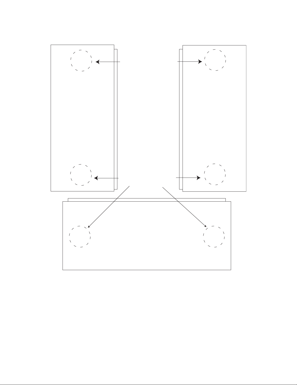
Fig. 1
Right PanelLeft Panel
Suggested Locations
for Wire Entries
Suggested Locations
for Wire Entries
Bottom Panel
- 4 - WPTV248ULseries
Page 5

Fig. 2
WPTV248UL
Fig. 2a
Fig. 2b
24VAC or 28VAC
output 1 (Follow
same procedure
using terminals
2P & N through
8P & N
outputs 2 through 8)
Primary
In-line
Fuse
1 2 3 4 5 6 7 8
P
FUSED POWER OUTPUTS
N
COMMON POWER OUTPUTS
Class 1 Outputs
non power-
limited
XFMR
D1
R1
NPS
White
Lead
LED
INPUT
non power-
limited
MAIN FUSE
OFF
ON
Black
Lead
115VAC
Input
50/60 Hz.
Green
Lead
(Ground)
Black
Lead
ON OFF
Terminal Blocks for Fig. 2
24VAC or 28VAC
fused or PTC protected outputs
WPTV248ULseries - 5 -
1 through 8.
Page 6

Fig. 3
WPTV248ULCB
24VAC or 28VAC
output 1 (Follow
same procedure
using terminals
2P & N through
8P & N
outputs 2 through 8)
F1 F2 F3 F4 F5 F6 F7 F8
P
FUSED POWER OUTPUTS
N
COMMON POWER OUTPUTS
D1
R1
NPS
LED
MAIN FUSE
ON OFF
INPUT
Fig. 3a
Fig. 3a
ON OFF
24VAC configuration: Class 2 Not Wet/Class 3 Wet
28VAC configuration: Class 1
Primary
In-line Fuse
non power-
limited
XFMR
White
Lead
non power-
limited
Black
Lead
Green
Lead
(Ground)
Black
Lead
115VAC
Input
50/60 Hz.
Terminal Blocks for Fig. 3
24VAC or 28VAC
fused or PTC protected outputs
1 through 8.
- 6 - WPTV248ULseries
Page 7

Fig. 4
WPTV248175UL
Fig. 4a
XFMR
non power-
limited
Black
Lead
White
Lead
Green
Lead
(Ground)
MAIN FUSE
115VAC
Input
50/60 Hz.
Fig. 4b
Illuminated Power Disconnect
Circuit Breaker with manual reset
Terminal Blocks for Fig. 4
24VAC or 28VAC
fused or PTC protected outputs
WPTV248ULseries - 7 -
1 through 8.
Page 8

Fig. 5
WPTV248175ULCB
Fig. 5a
F1 F2 F3 F4 F5 F6 F7 F8
P
FUSED POWER OUTPUTS
N
COMMON POWER OUTPUTS
non power-
limited
XFMR
D1
R1
NPS
Black
Lead
White
Lead
LED
INPUT
Green
Lead
(Ground)
MAIN FUSE
115VAC
Input
50/60 Hz.
Fig. 5b
Illuminated Power Disconnect
Circuit Breaker with manual reset
Terminal Blocks for Fig. 5
24VAC or 28VAC
fused or PTC protected outputs
- 8 - WPTV248ULseries
1 through 8.
Page 9

Fig. 6
WPTV248300UL
24VAC or 28VAC
output 1 (Follow
same procedure using
terminals 2P & N
through 8P & N
outputs 2 through 8)
Fig. 6a
MAIN FUSE
Fig. 6b
Class 1 Outputs
XFMR*
non power-
limited
Black
Lead
White
Lead
Green
Lead
(Ground)
115VAC
Input
50/60 Hz
Illuminated Power Disconnect
Circuit Breaker with manual reset
Terminal Blocks for Fig. 6
24VAC or 28VAC
fused or PTC protected outputs
1 through 8.
WPTV248ULseries - 9 -
Page 10

Fig. 7
WPTV248300ULCB
Fig. 7a
F1 F2 F3 F4 F5 F6 F7 F8
MAIN FUSE
24VAC or 28VAC
output 1 (Follow
same procedure using
terminals 2P & N
through 8P & N
outputs 2 through 8)
P
FUSED POWER OUTPUTS
N
COMMON POWER OUTPUTS
24VAC configuration
Class 2 Not Wet/Class 3 Wet
XFMR*
D1
R1
NPS
LED
INPUT
non power-
limited
Green
(Ground)
Black
Lead
White
Lead
Lead
115VAC
Input
50/60 Hz
Fig. 7b
Illuminated Power Disconnect
Circuit Breaker with manual reset
Terminal Blocks for Fig. 7
24VAC or 28VAC
fused or PTC protected outputs
- 10 - WPTV248ULseries
1 through 8.
Page 11

Wall Mount Installation
1- Place unit at desired location and secure with mounting
screws (not included) (Fig. 8, pg. 7).
Fig. 8
Pole Installation Using Optional Pole Mount Kit PMK1 (not included):
This installation should be made by qualified service personnel. This product contains no serviceable parts. PMK1 is intended for use with Altronix outdoor rated power supplies or accessories housed in WP1, WP2, WP3 and WP4 enclosures.
Brackets are designed for use with the Wormgear Quick Release Straps (two included).
1. Thread one (1) wormgear quick release strap through the slots on the back of a mounting bracket (Fig. 9, pg. 7).
2. Once the desired height of the top Pole Mount bracket is achieved, tighten the straps down by sliding open end
of the strap through the locking mechanism on the strap, then tighten the screw with
flat head screwdriver or 5/16” hex socket driver (Fig. 10, pg. 7).
Fig. 9
Fig. 10
Fig. 11
3. Attach the bottom bracket to the enclosure by inserting bolts through the
flange of the enclosure and into the bracket, tightening bolts with a
7/16” hex socket (Fig. 12, pg. 7).
4. Thread the second wormgear quick release strap through the slots on the
back of the bottom mounting bracket (Fig. 9, pg. 7).
5. Mount enclosure onto the top bracket by inserting bolts through
flange of the enclosure and into the bracket,
tightening bolts with a 7/16” hex socket (Fig. 11, pg. 7).
6. Tighten the straps of the bottom bracket down by sliding the open end of
the strap through the locking mechanism on the strap, then tighten screw
with flat head screwdriver or 5/16” hex socket driver (Fig. 13/13a, pg. 7).
7. Clip excess straps.
Fig. 13 - 2” to 8”(50.8mm to 203.2mm) Fig. 13a - 5” (127mm) square pole
diameter round pole
Fig. 12
WPTV248ULseries - 11 -
Page 12

6”
152.4mm
Enclosure Dimensions (H x W x D approximate):
12” x 8” x 6” (304.8mm x 203.2mm x 152.4mm)
8”
203.2mm
14”
355.6mm
13”
330mm
4.05”
103mm
MOUNTING PANEL
GALVANIZED
12”
305mm
6.7”
170mm
CARBON STEEL SHEET
9.84”
250mm
0.08”
2mm
4.21”
107mm
Altronix is not responsible for any typographical errors.
140 58th Street, Brooklyn, New York 11220 USA, 718-567-8181, fax: 718-567-9056
web site: www.altronix.com, e-mail: info@altronix.com. Lifetime Warranty, Made in U.S.A.
- 12 - WPTV248ULseries
II1WPTV248UL Series E23P
MEMBER
 Loading...