

Page 1

DC Outdoor Power Supply/Chargers
Installation Guide
Models Include:
WayPoint3 WayPoint7
- 2.5A @ 12VDC or 24VDC. - 6A @ 12VDC or 24VDC.
- 115/230VAC input. - 115VAC input.
WayPoint5 WayPoint7V
- 3.5A @ 12VDC or 24VDC. - 6A @ 12VDC or 24VDC.
- 115/230VAC input. - 230VAC input.
WayPoint1012V WayPoint104
- 10A @ 12VDC. - 10A @ 24VDC.
- 230VAC input. - 115VAC input.
Rev. 080911DCPL More than just power.™
Page 2

Overview:
Altronix DC Outdoor Power Supply/Chargers provide 12VDC or 24VDC and are designed to be conveniently located
where power is required.
WayPoint DC Reference Chart:
Altronix
Model
Number
WayPoint3
WayPoint5
WayPoint7
WayPoint7V
WayPoint1012V
WayPoint104
Output
Current
2.5A 12VDC or 24VDC ON OFF 0.95A 0.6A
3.5A 12VDC or 24VDC ON OFF 0.95A 0.6A
6A 12VDC or 24VDC ON OFF 1.9A N/A
6A 12VDC or 24VDC ON OFF N/A 0.95A
10A 12VDC N/A N/A 3.0A
10A 24VDC N/A 1.9A N/A
Output Voltage
12VDC 24VDC
SW1
115VAC/60Hz
Input
Current Draw
230VAC/50Hz
Input
Current Draw
Specifications:
Input:
• Input: 115VAC, 60Hz or 230VAC, 50Hz.
Output:
• 12VDC or 24VDC selectable output
(12VDC only for WayPoint1012V;
24VDC only for WayPoint104).
• Filtered and electronically regulated output.
• Thermal overload and short circuit protection.
Battery Backup:
• Built-in charger for sealed lead acid or gel type batteries.
• Maximum charge current 500mA for WayPoint3/5/7/7V;
700mA for WayPoint1012V and WayPoint104.
• Automatic switch over to stand-by battery.
Features:
• AC and DC power LED indicators.
• Ease of installation saves time and eliminates costly labor.
• Includes battery leads.
Accessories:
• Optional PMK1 Pole Mount Kit simplifies installation of
outdoor units.
Enclosure:
• NEMA 4/4X, IP66-11 Rated enclosure for outdoor use.
• Enclosure Dimensions (H x W x D approx.):
13.32” x 11.32” x 5.6”
(338.28mm x 287.528mm x 142.24mm).
• Enclosure accommodates up to two (2) 12AH batteries.
Installation Instructions:
Wiring methods should be in accordance with the National Electrical Code/NFPA 70/NFPA 72/ANSI, and with all local
codes and authorities having jurisdiction.
1. Remove back plane from the enclosure prior to mounting (do not discard hardware).
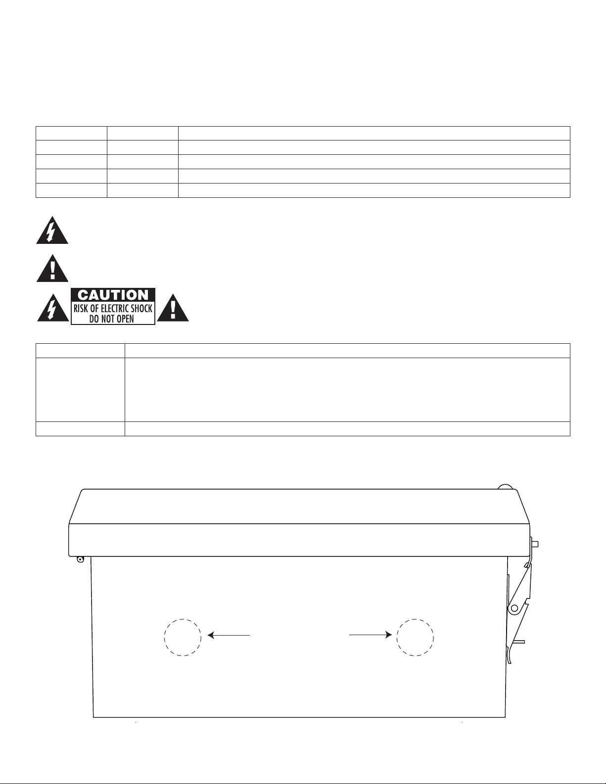
2. Mark and drill desired inlets on the enclosure to facilitate wiring (Fig. 1, pg. 3).
3. Mount unit in the desired location. For wall mounting refer to Fig. 5, pg. 7.
For pole mounting installation refer to pg. 7 - (Using Optional Altronix Pole Mount Kit PMK1 - not included).
4. Install back plane inside the enclosure with hardware.
5. Set power switch to the OFF position (Fig. 2b, pg. 4, Fig. 4a, pg. 6).
6. Connect AC power (115VAC or 230 VAC) to the terminals marked [L & N], connect ground to the terminal
marked [G] (Fig. 2-4, pgs. 4-6). Wire gauge range of connectors is 14 AWG to 11 AWG (1.6 mm to 2.5 mm diameter).
7. Select the desired DC output voltage by setting SW1 to the appropriate position for models WayPoint3, WayPoint5,
WayPoint7, and WayPoint7V (Reference Chart above) (Fig. 2a, pg. 4). WayPoint1012V provides 12VDC only.
WayPoint104 provides 24VDC only.
8. Set power switch to the ON position (Fig. 2b, pg. 4, Fig. 4a, pg. 6).
9. Measure output voltage at the terminals marked [--- DC +] before connecting devices (Fig. 2c, pg. 4, Fig. 3a, pg. 5,
Fig. 4b, pg. 6). This helps avoiding potential damage.
Note: Power supplies mounted in weatherproof enclosures should be derated by approximately 50%
due to the harsh environmental conditions.
10. Set power switch to the OFF position (Fig. 2b, pg. 4, Fig. 4a, pg. 6).
11. Connect devices to be powered to the terminals marked [--- DC +] (Fig. 2c, pg. 4, Fig. 3a, pg. 5, Fig. 4b, pg. 6).
12. Connect optional stand-by battery to the terminals marked [--- BAT +]. Battery leads included. Enclosure
accommodates up to two (2) 12AH batteries. If larger batteries are required, they need to be mounted in a separate
NEMA rated enclosure adjacent to the power supply (Fig. 2c, pg. 4, Fig. 3b, pg. 5, Fig. 4b, pg. 6).
Note: When batteries are not used, a loss of AC will result in a loss of output voltage.
13. Set power switch to the ON position (Fig. 2b, pg. 4, Fig. 3a, pg. 5).
14. Upon completion of the wiring secure enclosure door with latches and optional lock.
- 2 - DC Outdoor
Page 3
CAUTION: Equipment to be installed / serviced by authorized / trained personnel only.
Shut branch circuit power before installing / servicing equipment.
WARNING: When installing in a non-restricted service area, use lock or other fastened means on door
latches. This installation should be made by qualified service personnel and should conform to the National
Electrical Code and all local codes.
LED Diagnostics:
Red (DC) Green (AC) Power Supply Status
ON ON Normal operating condition.
ON OFF Loss of AC. Stand-by battery supplying power.
OFF ON No DC output. Short circuit or thermal overload condition.
OFF OFF No DC output. Loss of AC. Discharged or no battery present.
The lightning flash with arrow head symbol within an equilateral triangle is intended to alert the user to the
presence of an insulated DANGEROUS VOLTAGE within the product’s enclosure that may be of sufficient
magnitude to constitute an electric shock.
The exclamation point within an equilateral triangle is intended to alert the user to the presence of important
operating and maintenance (servicing) instructions in the literature accompanying the appliance.
CAUTION: To reduce the risk of electric shock do not open enclosure. There are
no user serviceable parts inside. Refer servicing to qualified service personnel.
Terminal Identification:
Terminal Legend Function/Description
WayPoint3: 12VDC or 24VDC @ 2.5A supply current.
WayPoint5: 12VDC or 24VDC @ 3.5A supply current.
--- DC +
– BAT + Stand-by battery connections. Maximum charge rate 500mA (700mA for WayPoint1012V/104).
WayPoint7: 12VDC or 24VDC @ 6A supply current.
WayPoint1012V: 12VDC @ 10A supply current.
WayPoint104: 24VDC @ 10A supply current.
Fig. 1
Suggested Locations
for Wiring Inlets
Bottom of Enclosure
DC Outdoor - 3 -
Page 4

Fig. 2 - WayPoint3, WayPoint5, WayPoint7, and WayPoint7V.
Fig. 2a
ON
OFF - 24V
ON - 12V
ON
OFF - 24V
ON - 12V
Fig. 2b
OFF ON
OFF ON
5A 250V
LG N
CAUTION
HIGH VOLTAGE
AC DC
--- BAT +--- DC +
Fig. 2c
--- BAT +--- DC +
- 4 - DC Outdoor
Page 5

Fig. 3 - WayPoint1012V
5A 250V
LG N
CAUTION
HIGH VOLTAGE
BAT FAIL
NC C NO NC C NO
VR1
15
--- DC +
--- DC +
Fig. 3a
+ BAT ---
AC DELAY
AC FAIL
+ BAT ---
Fig. 3b
DC Outdoor - 5 -
Page 6

Fig. 4 - WayPoint104
Fig. 4a
OFF ON
OFF ON
15
5A 250V
AC FAIL
NC C NO NC C NO
AC DC
LOW BAT
--- BAT +--- DC +
CAUTION
HIGH VOLTAGE
Fig. 4b
--- BAT + --- DC +
- 6 - DC Outdoor
Page 7

Wall Mount Installation
1- Place unit at desired location and secure with mounting
screws (not included) (Fig. 5, pg. 7).
Fig. 5
Pole Mounting Using Optional Pole Mount Kit PMK1 (not included):
This installation should be made by qualified service personnel. This product contains no serviceable parts. PMK1 is intended for use with Altronix outdoor rated power supplies or accessories housed in WP1, WP2, WP3 and WP4 enclosures.
Brackets are designed for use with the Wormgear Quick Release Straps (two included).
1. Thread one (1) wormgear quick release strap through the slots on the back of a mounting bracket (Fig. 6, pg. 7).
2. Once the desired height of the top Pole Mount bracket is achieved, tighten the straps down by sliding open end
of the strap through the locking mechanism on the strap, then tighten the screw with
flat head screwdriver or 5/16” hex socket driver (Fig. 6, pg. 7 and Fig. 7, pg. 7).
Fig. 8
Fig. 6
Fig. 7
3. Attach the bottom bracket to the enclosure by inserting bolts through the
flange of the enclosure and into the bracket, tightening bolts with a
7/16” hex socket (Fig. 8, pg. 7).
4. Thread the second wormgear quick release strap through the slots on the
back of the bottom mounting bracket (Fig. 6, pg. 7).
5. Mount enclosure onto the top bracket by inserting bolts through
flange of the enclosure and into the bracket,
tightening bolts with a 7/16” hex socket (Fig. 7, pg. 7).
6. Tighten the straps of the bottom bracket down by sliding the open end of
the strap through the locking mechanism on the strap, then tighten screw
with flat head screwdriver or 5/16” hex socket driver (Fig. 9/9a, pg. 7).
7. Clip excess straps.
Fig. 9 - 2” to 8”(50.8mm to 203.2mm) Fig. 9a - 5” (127mm) square pole
diameter round pole
Fig. 7
DC Outdoor - 7 -
Page 8

Enclosure Dimensions (H x W x D):
13.32” x 11.32” x 5.6” (338.28mm x 287.528mm x 142.24mm)
STAINLESS STEEL PIANO HINGE
8.00” (203.2mm)
Ø 0.32 (8.128mm) MOUNTING HOLE
TYP. 4 PLACES
(142.24mm)
5.60”
WITH RIVETS (Ø 0.375” (9.52mm) PADLOCK EYE).
PADLOCK LATCH AT TACHED
(342.9mm)
13.50”
(338.328mm)
13.32”
(323.85mm)
12.75”
(304.8mm)
12.00”
11.32” (287.528mm)
(40.894mm)
1.61”
(100.584mm)
3.96”
10-32 X 0.375” (9.525mm)
BRASS INSERT (X4)
10.75” (273.05mm)
8.25” (209.55mm)
10.00” (254mm)
10-32 X 0.25” (6.35mm)
BRASS INSERT (X2)
(260.35mm)
10.25”
Altronix is not responsible for any typographical errors.
140 58th Street, Brooklyn, New York 11220 USA, 718-567-8181, fax: 718-567-9056
web site: www.altronix.com, e-mail: info@altronix.com. Lifetime Warranty, Made in U.S.A.
- 8 - DC Outdoor
IIWayPointDC Series B07Q
MEMBER
 Loading...