

Page 1

DC Outdoor Power Supply/Chargers
Installation Guide
Models Include:
WayPoint-3
- 2.5 amp @ 12VDC or 24VDC.
- 115/230VAC input.
WayPoint-5
- 4 amp @ 12VDC or 24VDC.
- 115/230VAC input.
WayPoint-7
- 6 amp @ 12VDC or 24VDC.
- 115VAC input.
WayPoint-7V
- 6 amp @ 12VDC or 24VDC.
- 230VAC input.
Rev. 080911DCPL More than just power.™
Page 2
Overview:
These Altronix High Current Outdoor Power Supply/Chargers provide 12VDC or 24VDC and are designed to be
conveniently located where power is required.
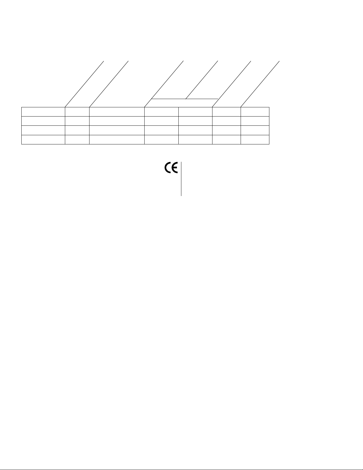
WayPoint DC Reference Chart:
Altronix
Model
Number
WayPoint-3
WayPoint-5
WayPoint-7
WayPoint-7V
Total Output Current
(Power)
2.5 amp 12VDC or 24VDC CLOSED OPEN 0.95 amp 0.6 amp
4 amp 12VDC or 24VDC CLOSED OPEN 0.95 amp 0.6 amp
6 amp 12VDC or 24VDC CLOSED OPEN 1.9 amp N/A
6 amp 12VDC or 24VDC CLOSED OPEN N/A 0.95
Output Voltage
12VDC
SW1
24VDC
115VAC/60Hz
Input Current Draw
230VAC/50Hz
Input Current Draw
Specifications:
• CECompliant(exceptWayPoint-7/7V).
• ACandDCpowerLEDindicators.
• Easeofinstallationsavestimeand
eliminates costly labor.
• Includesbatteryleads.
• NEMA 4/4X, IP66-11 Rated Outdoor Enclosure.
• OperatingAmbientTemperature:-20ºCto50ºC.
Enclosure Dimensions (H x W x D):
13.31” (338.074mm) x 11.31” (287.274mm) x
5.59” (141.986mm)
Installation Instructions:
Wiring methods shall be in accordance with the National Electrical Code/NFPA 70/NFPA 72/ANSI, and with all local
codes and authorities having jurisdiction.
1. Remove back plane from enclosure prior to mounting (do not discard hardware).
2. Mark and drill desired inlets on the enclosure to facilitate wiring (Fig. 1, pg. 3).
3. Mount unit in desired location. Mark and drill holes to line up with the top and bottom holes of the enclosure flange.
Secure enclosure with appropriate fasteners (Fig. 5 & 5a, pg. 7 and Fig. 6, pg. 8).
4. Mount back plane to enclosure with hardware.
5. Set power switch to the OFF position (Fig. 2b, pg. 4, Fig. 3b, pg. 5, Fig. 4b, pg. 6).
6. Connect AC power (115VAC) to terminals marked [L & N], connect ground to terminal
marked [G] (Fig. 2-4, pgs. 4-6). Use 18 AWG or larger for all power connections (Battery, DC output).
7. Select the desired DC output voltage by setting SW1 to the appropriate position (Reference Chart above)
(Fig. 2a, pg. 4, Fig. 3a, pg. 5, Fig. 4a, pg. 6).
8. Set power switch to the ON position (Fig. 2b, pg. 4, Fig. 3b, pg. 5, Fig. 4b, pg. 6).
9. Measure output voltage at terminals marked [--- DC +] before connecting devices (Fig. 2c, pg. 4, Fig. 3c, pg. 5,
Fig. 4c, pg. 6). This helps avoid potential damage.
Note: Power supplies mounted in weatherproof enclosures should be derated by approximately
50% due to harsh environmental conditions.
10. Set power switch to the OFF position (Fig. 2b, pg. 4, Fig. 3b, pg. 5, Fig. 4b, pg. 6).
11. Connect devices to be powered to terminals marked [--- DC +] (Fig. 2c, pg. 4, Fig. 3c, pg. 5, Fig. 4c, pg. 6).
12. Connect optional stand-by battery to terminals marked [+ BAT --- ] battery leads included
(a separate enclosure is needed for batteries) (Fig. 2c, pg. 4, Fig. 3c, pg. 5, Fig. 4c, pg. 6).
Note: When batteries are not used, a loss of AC will result in a loss of output voltage.
13. Set power switch to the ON position (Fig. 2b, pg. 4, Fig. 3b, pg. 5, Fig. 4b, pg. 6).
14. Upon completion of wiring, secure enclosure door with latches and optional lock.
Caution: Equipment to be installed / serviced by authorized / trained personnel only.
Shut branch circuit power before installing / servicing equipment.
WARNING: To reduce the risk of fire or electric shock.
This installation should be made by qualified service personnel and should conform to all local codes
and in accordance with the National Electrical Code.
- 2 - DC Outdoor
Page 3

LED Diagnostics:
Bottom of Enclosure
Suggested Locations
for Wiring Inlets
Red (DC) Green (AC) Power Supply Status
ON ON Normal operating condition.
ON OFF Loss of AC. Stand-by battery supplying power.
OFF ON No DC output. Short circuit or thermal overload condition.
OFF OFF No DC output. Loss of AC. Discharged or no battery present.
The lightning flash with arrow head symbol within an equilateral triangle is intended to alert the user to the
presence of an insulated “DANGEROUS VOLTAGE” within the products enclosure that may be of sufficient
magnitude to constitute an electric shock.
The exclamation point within an equilateral triangle is intended to alert the user to the presence of important
operating and maintenance (servicing) instructions in the literature accompanying the appliance.
CAUTION: To reduce the risk of electric shock do not open enclosure. There are
no user serviceable parts inside. Refer servicing to qualified service personnel.
Terminal Identification:
Terminal Legend Function/Description
WayPoint-3 12VDC or 24VDC @ 2.5 amp continuous supply current.
--- DC +
WayPoint-5 12VDC or 24VDC @ 4 amp continuous supply current.
WayPoint-7 12VDC or 24VDC @ 6 amp continuous supply current.
+ BAT – Stand-by battery connections. Maximum charge rate 500mA.
Fig. 1
DC Outdoor - 3 -
Page 4

Fig. 2 - WayPoint-3
LGN
OFF ON
OFF ON
OPEN - 24VDC
CLOSED - 12VDC
OPEN - 24VDC
CLOSED - 12VDC
CAUTION
HIGH VOLT AGE
-- - BAT + -- - DC +
AC DC
-- - BAT + - - - DC +
5A 250V
Fig. 2b
Fig. 2a
Fig. 2c
- 4 - DC Outdoor
Page 5

Fig. 3 - WayPoint-5
LGN
OFF ON
OPEN - 24VDC
CLOSED - 12VDC
-- - BAT + -- - DC +
AC DC
5A 250V
OFF ON
OPEN - 24VDC
CLOSED - 12VDC
-- - BAT + - - - DC +
CAUTION
HIGH VOLT AGE
Fig. 3b
Fig. 3a
Fig. 3c
DC Outdoor - 5 -
Page 6

Fig. 4 - WayPoint-7 and WayPoint-7V
LGN
OFF ON
OPEN - 24VDC
CLOSED - 12VDC
-- - BAT + - - - DC +
AC DC
5A 250V
OFF ON
OPEN - 24VDC
CLOSED - 12VDC
-- - BAT + - - - DC +
CAUTION
120VAC
Fig. 4b
Fig. 4a
Fig. 4c
- 6 - DC Outdoor
Page 7

Wall Mount Installation
1- Place unit at desired location and secure with mounting screws
(not included) (Fig. 5 and Fig. 5a, pg. 7).
Fig. 5
Fig. 5a
DC Outdoor - 7 -
Page 8

1.61”
(40.894mm)
3.96”
(100.584mm)
5.60”
(142.24mm)
10-32 X 0.375” (9.525mm)
BRASS INSERT (X4)
STAINLESS STEEL PIANO HINGE
11.32” (287.528mm)
13.32”
(338.328mm)
PADLOCK LATCH A T T A CHED
WITH RIVETS (Ø 0.375” (9.52mm) PADLOCK EYE).
10.75” (273.05mm)
10.00” (254mm)
8.25” (209.55mm)
10.25”
(260.35mm)
12.00”
(304.8mm)
13.50”
(342.9mm)
10-32 X 0.25” (6.35mm)
BRASS INSERT (X2)
Ø 0.32 (8.128mm) MOUNTING HOLE
TYP. 4 PLACES
12.75”
(323.85mm)
8.00” (203.2mm)
Enclosure Dimensions (H x W x D):
13.31” (338.074mm) x 11.31” (287.274mm) x 5.59” (141.986mm)
Fig. 6
Altronix is not responsible for any typographical errors.
14058thStreet,Brooklyn,New York11220USA,718-567-8181,fax:718-567-9056
website:www.altronix.com,e-mail:info@altronix.com, LifetimeWarranty,MadeinU.S.A.
IIWayPointDC_PL I07K
- 8 - DC Outdoor
MEMBER
 Loading...