

Page 1

WayPoint562
High Current Outdoor Power Supply/Charger
Installation Guide
Rev. 062117
More than just power.
TM
Page 2

Altronix WayPoint562 provides 120W for NetWay Spectrum switches with 1Gb SFP ports. It converts 115VAC,
LGN
230VAC 115VAC
5A 250VA
--- DC +– BAT +
To stand-by
batteries
115/230VAC
Input
56VDC Output
to device
to be powered
60Hz or 230VAC, 50Hz input into a 56VDC at 2.2A of continuous supply current (see specifications).
It also features a built-in charger for sealed lead acid or gel type batteries.
Specifications:
Overview:
Agency Listing:
• CE European Conformity.
Input:
• 115VAC, 60 Hz, 2.5A or 230VAC, 50Hz, 1.3A.
Output:
• 56VDC/120W output.
• 2.2A continuous supply current.
• Filtered and electronically regulated output.
• Short circuit and thermal overload protection.
Electrical:
• System AC input VA requirement: 300VA.
Battery Backup:
• Built-in charger for sealed lead acid or
gel type batteries.
• Automatic switch over to stand-by battery
when AC fails.
• Battery leads included.
Mechanical:
• NEMA 4/4X, IP66-11 Rated enclosure for
outdoor use.
• Lightweight molded fiberglass reinforced
polyester enclosure is corrosion resistant and
does not contain halogens.
• Lockable stainless steel latches.
• Integral flanges simplify wall or pole mounting.
Enclosure Dimensions (H x W x D approx.):
13.31” x 11.31” x 5.59”
(338.1mm x 287.3mm x 142mm).
Accessories:
• Optional PMK1 Pole Mount Kit simplifies
installation of outdoor units.
Wiring methods should be in accordance with the National Electrical Code/NFPA 70/NFPA 72/ANSI, and
Installation Instructions:
with all local codes and authorities having jurisdiction. Use 14 AWG or larger for all power connections. This
unit does not have any serviceable parts.
1. Remove backplane from the enclosure prior to mounting (do not discard hardware).
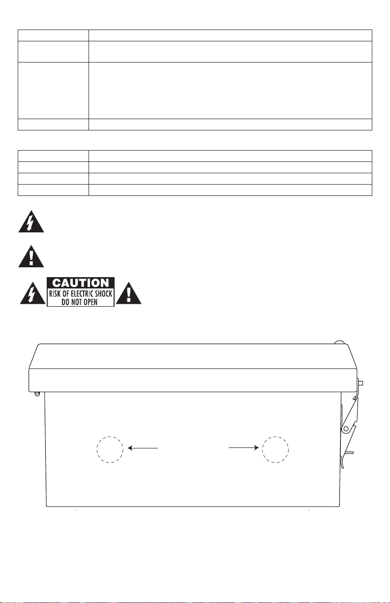
2. Mark and drill desired inlets on the enclosure to facilitate wiring (Fig. 1, pg. 3).
3. Mount unit in the desired location. Refer to Pg. 7 for pole or wall mounting instructions.
4. Mount backplane to the enclosure with hardware.
5. To facilitate wire entry utilize weather tight NEMA 4 rated connectors, bushings and cable.
6. Set PoE201 to the proper AC input voltage via input voltage switch (Fig. 2a, pg. 4).
7. Connect AC power from overcurrent protective device circuit breaker (20A @ 115VAC, 60Hz,
16A @ 230VAC, 50/60Hz) as follows: Green branch wire connects to earth (safety) ground ,
Line connects to the terminal marked [L] and Neutral connects to the terminal marked [N] on
power supply board (Fig. 2, pg. 4).
Use 14AWG or larger for all power connections (Battery, DC output, AC input).
Keep power-limited wiring separate from non power-limited wiring (115VAC/230VAC 50/60Hz
Input, Battery Wires). Minimum 0.25” spacing must be provided.
CAUTION: Do not touch exposed metal parts.
Shut branch circuit power before installing or servicing equipment.
There are no user serviceable parts on unit.
Refer installation and servicing to qualified service personnel.
8. Measure output voltage before connecting devices. This helps avoiding potential damage.
9. Connect devices to be powered to the terminals marked [– DC +].
10. When the use of stand-by batteries is desired, they must be lead acid or gel type.
Connect batteries to the terminals marked [– BAT +] (battery leads included).
11. When batteries are not used, a loss of AC will result in the loss of output voltage.
12. Upon completion of wiring secure enclosure door with latches and optional lock.
Caution: Equipment to be installed / serviced by authorized / trained personnel only.
Shut branch circuit power before installing / servicing equipment.
WARNING: When installing in a non-restricted service area use lock or other fastened means on door
latches. This installation should be made by qualified service personnel and should conform to the
National Electrical Code and all local codes.
- 2 - WayPoint562
Page 3
Technical Specifications:
Parameter Description
Input power
requirements
Environmental
Conditions
Weights (approx.)
115VAC, 60Hz, 2.5A or 230VAC, 50/60Hz, 1.3A.
Operating Ambient Temperature:
60W: -40ºC to 75ºC (-40ºF to 167ºF); 75W: -40ºC to 70ºC (-40ºF to 158ºF);
100W: -40ºC to 55ºC (-40ºF to 131ºF); 120W: -40ºC to 45ºC (-40ºF to 113ºF).
Relative Humidity: 85%, +/- 5%.
Storage Temperature: -40ºC to 85ºC (-40ºF to 185ºF).
Operating Altitude: -304.8 to 2,000m.
Product weigtht: 8.5 lb. (3.9 kg) | Shipping weigtht: 9.7 lb. (4.4 kg).
Terminal Identification:
Terminal Legend Function/Description
L, G, N
– DC +
– BAT +
The lightning flash with arrowhead symbol within an equilateral triangle is intended to alert the user
to the presence of an insulated DANGEROUS VOLTAGE within the product’s enclosure that may
be of sufficient magnitude to constitute an electric shock.
The exclamation point within an equilateral triangle is intended to alert the user to the presence of
important operating and maintenance (servicing) instructions in the literature accompanying the
appliance.
Connect 115VAC/230VAC to these terminals: L to Hot, N to Neutral.
56VDC @ 2.2A continuous supply current.
Stand-by battery connections. Maximum charge rate 0.7A.
CAUTION: To reduce the risk of electric shock do not open
enclosure. There are no user serviceable parts inside.
Refer servicing to qualified service personnel.
Fig. 1
Suggested Locations
for Wiring Inlets
Bottom of Enclosure
WayPoint562 - 3 -
Page 4

Fig. 2 - WayPoint562
230VAC 115VAC
Fig. 1a
56VDC Output
--- DC +– BAT +
5A 250VA
230VAC 115VAC
to device
to be powered
To stand-by
batteries
LGN
115/230VAC
Input
- 4 - WayPoint562
Page 5

Notes:
WayPoint562 - 5 -
Page 6

Notes:
- 6 - WayPoint562
Page 7

Wall Mount Installation
1- Place unit at desired location and secure with mounting
screws (not included) (Fig. 3, pg. 7).
Fig. 3
Pole Mounting Using Optional Pole Mount Kit PMK1 (not included):
This installation should be made by qualified service personnel. This product contains no serviceable parts.
PMK1 is intended for use with Altronix outdoor rated power supplies or accessories housed in WP1, WP2, WP3
and WP4 enclosures. Brackets are designed for use with the Wormgear Quick Release Straps (two included).
1. Thread one (1) wormgear quick release strap through the slots on the back of a mounting bracket (Fig. 4, pg. 7).
2. Once the desired height of the top Pole Mount bracket is achieved, tighten the straps down by sliding open
end of the strap through the locking mechanism on the strap, then tighten the screw with
flat head screwdriver or 5/16” hex socket driver (Fig. 5, pg. 8 and Fig. 7, pg. 7).
Fig. 6
Fig. 8a
5” (127mm) square pole
Fig. 7
Fig. 5
Fig. 8
2” to 8”(50.8mm to 203.2mm)
diameter round pole
Fig. 4
3. Attach the bottom bracket to the enclosure by inserting bolts through the flange of the enclosure and into the
bracket, tightening bolts with a 7/16” hex socket (Fig. 6, pg. 7).
4. Thread the second wormgear quick release strap through the slots on the back of the bottom mounting bracket
(Fig. 4, pg. 7).
5. Mount enclosure onto the top bracket by inserting bolts through flange of the enclosure and into the bracket,
tightening bolts with a 7/16” hex socket (Fig. 6, pg. 7).
6. Tighten the straps of the bottom bracket down by sliding the open end of the strap through the locking
mechanism on the strap, then tighten screw with flat head screwdriver or 5/16” hex socket driver
(Fig. 4, pg. 7).
7. Clip excess straps.
WayPoint562 - 7 -
Page 8

8.25” (209.6mm)
10.75” (273.1mm)
3.96”
(100.6mm)
Enclosure Dimensions (H x W x D approx.):
13.31” x 11.31” x 5.59” (338.1mm x 287.3mm x 142mm)
10.25”
(260.4mm)
10-32 X 0.25” (6.4mm)
BRASS INSERT (X2)
10.00”
(254mm)
12.00”
13.50”
(342.9mm)
(304.8mm)
12.75”
(323.9mm)
10-32 X 0.375” (9.6mm)
BRASS INSERT (X4)
PADLOCK LATCH ATTACHED WITH RIVETS
1.61”
(40.9mm)
11.31”
13.31”
(338.1mm)
(287.3mm)
STAINLESS STEEL PIANO HINGE
(Ø 0.375” (9.5mm) PADLOCK EYE).
5.59”
(142mm)
Altronix is not responsible for any typographical errors.
140 58th Street, Brooklyn, New York 11220 USA | phone: 718-567-8181 | fax: 718-567-9056
website: www.altronix.com | e-mail: info@altronix.com | Lifetime Warranty | Made in U.S.A.
IIWayPoint562 C29R
- 8 - WayPoint562
Ø 0.32 (8.1mm) MOUNTING HOLE
TYP. 4 PLACES
8.00” (203.2mm)
MEMBER
 Loading...