

Page 1
WayPoint307A - AC Outdoor Power Supply
Rev. 080911
Overview:
WayPoint307A Outdoor Power Supply provides 24VAC or 28VAC distributed via two outputs for powering CCTV
cameras, heaters, and other video accessories.
Specifications:
Agency Listing:
• CE Compliant.
Input:
• Input: 277VAC, 60Hz, 1.75A.
Output:
• Output options:
a. 24VAC @ 12.5A max.
b. 28VAC @ 10A max.
c. Both 24VAC and 28VAC not to exceed 10A max.
• Output fuses rated @ 15A 32V.
Installation Instructions:
Unit should be installed in accordance with The National Electrical Code and all applicable Local Regulations.
1. Remove back plane from enclosure prior to mounting (do not discard hardware).
2. Mark and drill desired inlets on the enclosure to facilitate wiring (Fig. 2, pg. 2).
3. Mount unit in desired location. Mark and drill holes that line up with the top and bottom holes of the enclosure flange.
Secure enclosure with appropriate fasteners (Fig. 3, pg. 3).
4. Mount back plane to enclosure with hardware.
5. To facilitate wire entry, utilize weather tight NEMA 4 rated connectors, bushings and cable.
6. Connect unswitched AC power (277VAC/60 Hz) to terminals marked [L, G, N] (Fig. 1, pg. 2). Wire gauge range of
connectors is 14 AWG to 11 AWG (1.6 mm to 2.5 mm diameter).
7. LEDs will illuminate indicating each output is powered (Fig. 1, pg. 2).
8. Measure output voltage on terminals marked [COM, 24V, 28V] before connecting devices (Fig. 1, pg. 2).
This helps avoid potential damage.
9. For 24VAC output connect devices to terminals marked [COM, 24V] (Fig. 1, pg. 2).
For 28VAC output connect devices to terminals marked [COM, 28V] (Fig. 1, pg. 2).
10. Upon completion of wiring, secure enclosure door with latches and optional lock.
Caution: Equipment to be installed / serviced by authorized / trained personnel only.
Shut branch circuit power before installing / servicing equipment.
Features:
• Individual power output LED indicators.
• Spare fuses included.
Enclosure:
• NEMA 4/4X, IP66-11 Rated enclosure for
outdoor use.
• Integral flanges simplify wall or pole mounting.
• Enclosure Dimensions (H x W x D approx.):
13.31” x 11.31” x 5.59”
(338.074 mm x 287.274 mm x 141.986 mm).
WARNING: When installing in a non-restricted service area use lock or other fastened means on door
latches. This installation should be made by qualified service personnel and should conform to the National
Electrical Code and all local code.
Terminal and LED Identification Chart:
Output
Terminals
COM and 24V 24VAC
COM and 28V 28VAC
The lightning flash with arrow head symbol within an equilateral triangle is intended to alert the user to the
presence of an insulated DANGEROUS VOLTAGE within the product’s enclosure that may be of sufficient
magnitude to constitute an electric shock.
The exclamation point within an equilateral triangle is intended to alert the user to the presence of important
operating and maintenance (servicing) instructions in the literature accompanying the appliance.
- 1 - WayPoint-307A
LED
ON OFF
Normal operating condition. No AC output. Blown fuse, AC failure.
CAUTION: To reduce the risk of electric shock do not open enclosure. There are
no user serviceable parts inside. Refer servicing to qualified service personnel.
LED Status
Page 2
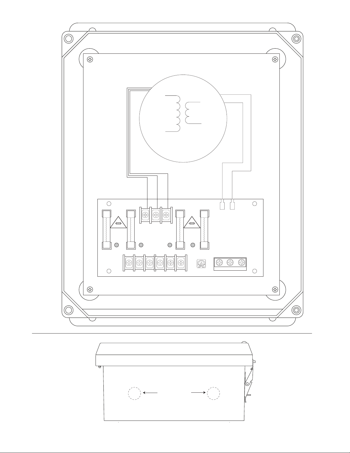
Fig. 1
XFMR*
Fig. 2
28V 24V COM
15A 32V
24VAC 28VAC
OUT1
COM 24V 28V
INPUT
INPUT
24VAC 28VAC
OUT2
COM 24V 28V
15A 32V
LGN
CAUTION
277VAC
Suggested Locations
for Wiring Inlets
Bottom of Enclosure
WayPoint-307A - 2 -
Page 3

Wall Mount Installation
1- Place unit at desired location and secure with mounting
screws (not included) (Fig. 3, pg. 3).
Fig. 3
Pole Mounting Using Optional Pole Mount Kit PMK1 (not included):
This installation should be made by qualified service personnel. This product contains no serviceable parts. PMK1 is intended for use with Altronix outdoor rated power supplies or accessories housed in WP1, WP2, WP3 and WP4 enclosures.
Brackets are designed for use with the Wormgear Quick Release Straps (two included).
1. Thread one (1) wormgear quick release strap through the slots on the back of a mounting bracket (Fig. 4, pg. 3).
2. Once the desired height of the top Pole Mount bracket is achieved, tighten the straps down by sliding open end
of the strap through the locking mechanism on the strap, then tighten the screw with
flat head screwdriver or 5/16” hex socket driver (Fig. 5, pg. 3 and Fig. 6, pg. 3).
Fig. 6
Fig. 4
Fig. 5
3. Attach the bottom bracket to the enclosure by inserting bolts through the
flange of the enclosure and into the bracket, tightening bolts with a
7/16” hex socket (Fig. 7, pg. 3).
4. Thread the second wormgear quick release strap through the slots on the
back of the bottom mounting bracket (Fig. 4, pg. 3).
5. Mount enclosure onto the top bracket by inserting bolts through
flange of the enclosure and into the bracket,
tightening bolts with a 7/16” hex socket (Fig. 6, pg. 3).
6. Tighten the straps of the bottom bracket down by sliding the open end of
the strap through the locking mechanism on the strap, then tighten screw
with flat head screwdriver or 5/16” hex socket driver (Fig. 8/8a, pg. 3).
7. Clip excess straps.
Fig. 8 - 2” to 8”(50.8mm to 203.2mm) Fig. 8a - 5” (127mm) square pole
diameter round pole
Fig. 7
- 3 - WayPoint-307A
Page 4

Enclosure Dimensions (H x W x D):
13.31” x 11.31” x 5.59” (338.074 mm x 287.274 mm x 141.986 mm)
STAINLESS STEEL PIANO HINGE
8.00” (203.2mm)
Ø 0.32 (8.128mm) MOUNTING HOLE
TYP. 4 PLACES
(142.24mm)
5.60”
WITH RIVETS (Ø 0.375” (9.52mm) PADLOCK EYE).
PADLOCK LATCH ATTA CHED
(342.9mm)
13.50”
(338.328mm)
13.32”
(323.85mm)
12.75”
(304.8mm)
12.00”
11.32” (287.528mm)
(40.894mm)
1.61”
(100.584mm)
3.96”
10-32 X 0.375” (9.525mm)
BRASS INSERT (X4)
10.75” (273.05mm)
8.25” (209.55mm)
10.00” (254mm)
10-32 X 0.25” (6.35mm)
BRASS INSERT (X2)
(260.35mm)
10.25”
Altronix is not responsible for any typographical errors. Product specifications are subject to change without notice.
140 58th Street, Brooklyn, New York 11220 USA, 718-567-8181, fax: 718-567-9056
website: www.altronix.com, e-mail: info@altronix.com. Lifetime Warranty, Made in U.S.A.
WayPoint-307A - 4 -
IIWaypoint307A G07P
MEMBER
 Loading...