

Page 1
VR6
Voltage Regulator
Overview:
VR6 voltage regulator is designed to convert a 24VDC input into a regulated 5VDC or 12VDC output.
For use with Maximal, eFlow, ULX, and Trove series of power supplies.
Specifications:
Agency Listings:
• UL 294 6th Edition: Access Control System Units.*
• ULC-S319: Electronic Access Control Systems.**
Power Input / Output:
• Input: 24VDC @ 1.75A – Output: 5VDC @ 6A.
Input: 24VDC @ 3.5A – Output: 12VDC @ 6A.
Output:
• 5VDC or 12VDC regulated output.
• Output rating 6A max. non power-limited.
• Surge suppression.
*UL 294 Levels: Attack: I, Endurance: IV, Line security: I, Stand-by power: I.
**ULC-S319: Class 1.
Installation Instructions:
Wiring methods shall be in accordance with the National Electrical Code/NFPA 70/NFPA 72/ANSI,
with Canadian Electrical Code CSA C22.1, and with all local codes and authorities having jurisdiction.
Product is intended for indoor use only and should be installed by qualified personnel.
1. Mount VR6 in the desired location/enclosure.
Note: If VR6 needs to be elevated above the mounting surface, use included standoffs (regular for VR6 only, male/female for
mounting with PDS8/PDS8CB). Make sure to use metal standoff under the mounting hole with star pattern (Fig. 2b, pg. 2).
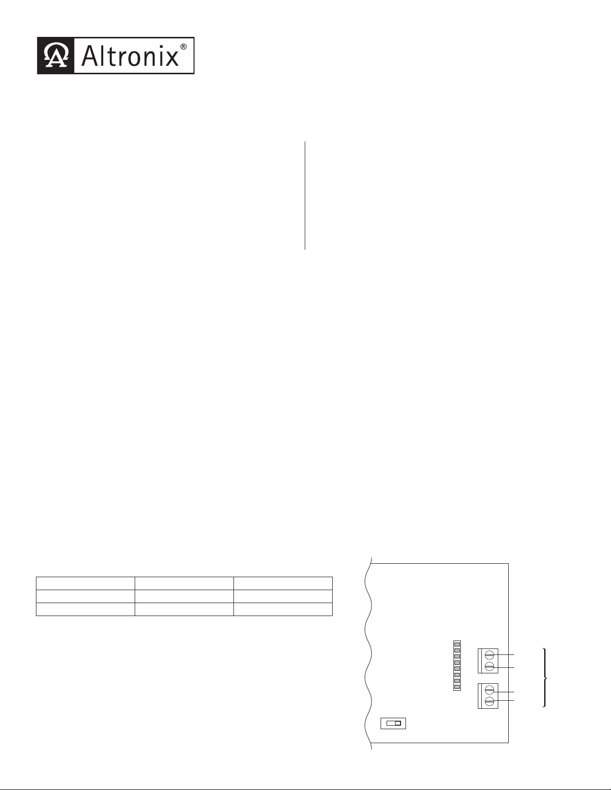
2. Connect 24VDC power source to the terminals marked [+ IN –] (Fig. 1 pg. 1).
3. Select output voltage 5VDC or 12VDC using switch [S1].
4. Connect power distribution module to the terminals marked [+ OUT –] (Fig. 1 pg. 1).
LED Indicators:
• Input and output LEDs.
Electrical:
• Operating temperature: 0º C to 49º C ambient.
• Humidity: 20 to 85%, non-condensing.
Mechanical:
• Product weight (approx.): 0.4 lbs. (0.18 kg).
• Shipping weight (approx.): 0.5 lbs. (0.23 kg).
Connecting PDS8/PDS8CB Board to VR6:
Refer to PDS8/PDS8CB Installation Instructions Rev. 070116
1. Mount VR6 in the desired location/enclosure.
2. Plug-in male 8-pin connector to female 8-pin receptacle on VR6 board (Fig. 2a, pg. 2).
3. Fasten standoffs (Fig. 2, pg. 2). Use metal standoff over mounting hole with star pattern (Fig. 2b, pg. 2).
4. Align 8-pin male connector with female receptacle of PDS8/PDS8CB, then mount (Fig. 2, pg. 2, Fig. 3a, pg. 2).
5. Connect 24VDC power supply to terminal marked [+ IN1 –] of PDS8/PDS8CB (Fig. 2, pg. 2).
6. Set each output (OUT1-OUT8) on PDS8/PDS8CB to route power from power supply 1 or 2 (jumper positions <1 OFF 2>)
(Fig. 3, pg. 2).
Note: Measure output voltage before connecting devices. This helps avoiding potential damage.
7. Turn power off before connecting devices.
8. Connect devices to terminal pairs 1 to 8, marked [P (Positive) - OUT1-OUT8, N (Negative)] (Fig. 3, pg. 2).
Note: For DC devices carefully observe polarity.
9. After all devices have been connected turn power on.
--
+ OUT
--
+ IN
Fig. 1
5VDC or
12VDC
Output
24VDC
Power
Supply
Input/Output Chart:
Input 5VDC Output 12VDC Output
24VDC @ 1.75A 6A max. N/A
24VDC @ 3.5A N/A 6A max.
VR6
Voltage Regulator
Altronix Corp.
Brooklyn, NY 11220
Made In USA
non
powerlimited
S1
ON-5V
OFF-12V
Page 2
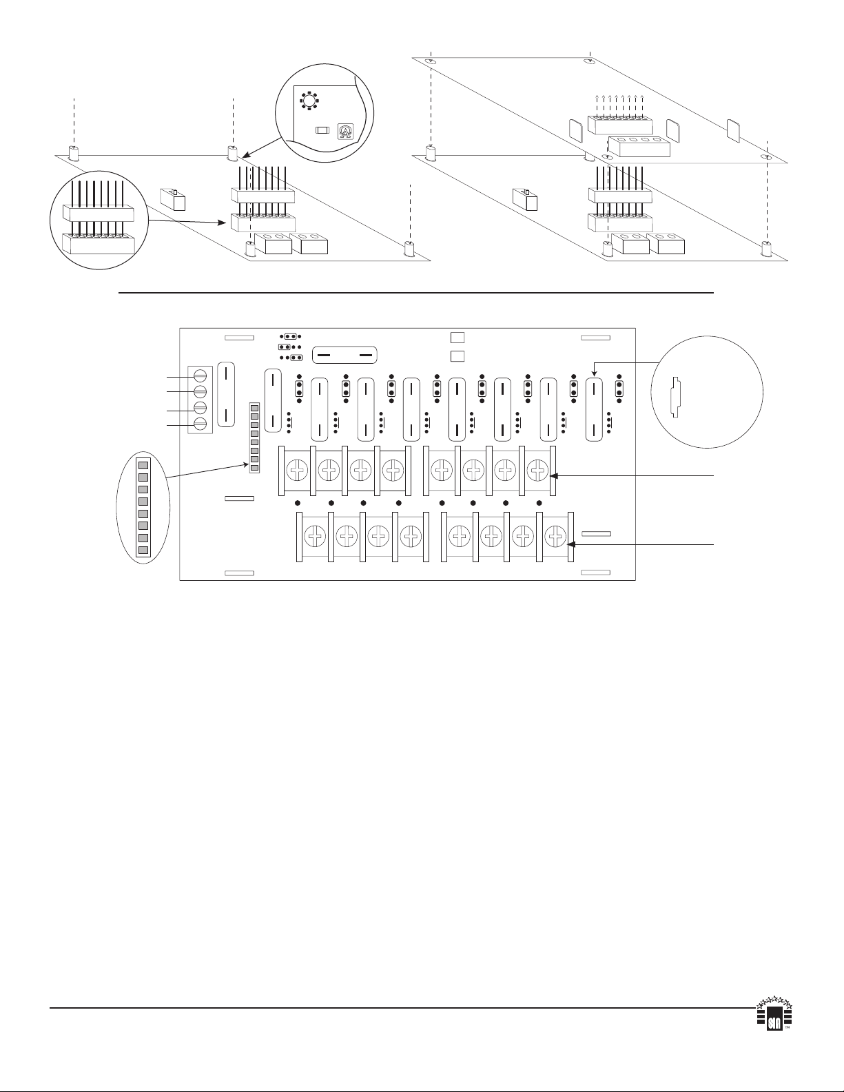
Fig. 2
C20
Fig. 2b
PDS8/PDS8CB
Fig. 3 - PDS8(CB)
Power
Supply 1
Power
Supply 2
Fig. 3a
Fig. 2a
+ INP1
--
+ INP2
--
DM1 +
IN2 Fuse
10
Common (--- )
DM2 +
--
--
+ OUT
+ IN
OFF
IN1
IN2
3
IN1 Fuse
10
<
1 off 2
>
Out1
<
1 off 2
3
>
PDS8
PDS8CB
<
1 off 2
333333
Out2
>
Out3
<
1 off 2
>
Out4
<
1 off 2
Out5
>
P
OUT1 OUT2 OUT3 OUT4 OUT5 OUT6 OUT7 OUT8
N
1 2 3 4 5 6 7 8
Common Power Outputs (NEG)
DM1+
VR6VR6
Dual Voltage
Power Distribution
Module
<
1 off 2
Out6
>
DM1 +
<
1 off 2
Out7
>
Common (--- )
DM2 +
<
1 off 2
>
+ IN1
Out8
+ IN
--
--
Common(-)
--
+ IN2
+ OUT
PDS8CB
--
PTC rated
@ 2A
(P) Positive
DC outputs
(N) Negative
DC outputs
Altronix is not responsible for any typographical errors.
140 58th Street, Brooklyn, New York 11220 USA | phone: 718-567-8181 | fax: 718-567-9056
website: www.altronix.com | e-mail: info@altronix.com | Lifetime Warranty | Made in U.S.A.
IIVR6 - Rev. 050517 E09R
MEMBER
 Loading...